installation instructions for top mount pull-out … · installation instructions for top mount...
TRANSCRIPT

INSTALLATION INSTRUCTIONSfor Top Mount Pull-Out Waste Containers - Frameless Cabinets
INSTRUCCIONES DE INSTALACIÓN Para Contenedores de Basura Corredizos de Montaje
Superior – Gabinetes sin MarcoNOTICE D’INSTALLATION
For Top Mount Pull-Out Waste Containers - Frameless Cabinet
Step 2: Attach cabinet member of slides flush with front of cabinet and the center of the slide 14 1/4” ( for 4WCTM-12DM1-343-FL, 15DM2-343-FL, 18DM2-419-FL, 27-4-597-FL) and 20 1/8” (for the 1550DM1-343-FL, and1850DM2-419FL) above floor. Use #8 x 5/8” low profile trusshead screws (included).Paso 2: Sujete el gabinete componente a los rieles alineado con el frente del gabinete y el centro del riel 14 1/4” (por el 4WCTM-12DM1-343-FL, 15DM2-343-FL, 18DM2-419-FL ó 27-4-597-FL y 20 1/8” ( por el 1550DM1-343-FL, y 1850DM2-419FL). Utilice #8 por 5/8” tornillos del trusshead del perfil bajo (incluidos).Etape 2: Attacher la pièce du caisson des coulisses à ras avec la façade du caisson et le centre de la coulisse à 361.95mm (14 1/4”) (pour les 4WCTM-12DM1-343-FL, 15DM2-343-FL, 18DM2-419-FL, ou 27-4-597-FL) et 511.17 mm (20 1/8”) (pour les 1550DM1-343-FL, et 1850DM2-419FL). Employez #8 par 5/8” ; vis de trusshead de profil bas (incluses).
Step 3: Install wood unit into cabinet, engaging product member slides into cabinet member slides push unit until it locks in place.Paso 3: Instale la pieza de madera en el armario de forma que las deslizaderas en el producto se entren en las deslizad-eras que están en el armario y empuje hasta que cierren.Étape 3: Installer l’ensemble en bois dans l’armoire en engageant les glissières du produit dans celles de l’armoire. Pousser sur l’ensemble jusqu’à ce qu’il s’enclenche.
INSTALLATION INSTRUCTIONSfor Top Mount Pull-Out Waste Containers WITH
Door Mounting Brackets
STEP 1:Install front bracket tofront side of slide.
STEP 2:Install rear bracket torear of slide.
For models: 4WCTM-12DM1, 4WCTM-15DM2 and 4WCTM-18DM2
STEP 3:Mount slide to cabinet if rear of cabinet is thinner then 1/2" installa 1/2" x 3" wide furringstrip to the back of thecabinet centered 14 1/4" from floor of cabinet.
STEP 4:Measure from insidecabinet wall to insideface frame (A) distanceshould be measuredthe same at rear of cabinet (B).
STEP 6:Install wood unit (with slides attached) into cabinet, engaging product member slides into cabinet memberslides, pushunit until itlocks in place.
Now you areready tomount thedoor.
STEP 7:See door mounting instructions on inside.
141/4"131/2"
STEP 5:Position the slide with front bracket on the face frame opening and move it forward until the self register stop hits theinside of the face frame opening.Bottom of slide should be 13 1/2"from cabinet floor. Install screw in slotted mounting hole, do nottighten. Extend the slide rear mounting bracket until it contacts the rear Furring strip. Bottom of slide should be13 1/2" from cabinet floor. Rear mounting bracket shouldbe the same distance from the side cabinet wall at rear ofslide as it is up front. Drive mounting screw in center horizontal slot of rear mounting bracket, tighten. Tighten screw in front bracket.
Face Frame
Cabinet MemberSlides
Furring Strips
FurringStrips
Product Member Cabinet Member
SelfRegister
Stop
141/4"
131/2" 131/2"Front View
Top View
(A)
(B)
Step 1: Remove cabinet member of both slides.Paso 1: Quite el gabinete componente que se encuentra en ambos rieles.Étape 1: Retirer la pièce du caisson des 2 coulisses.
I-WCTM-FL 06-08
14 1/4" or 20 1/8”
For models, Para los modelos, Pour les modèles: 4WCTM-12DM1-343-FL, 1550DM1-343-FL, 15DM2-343-FL, 18DM2-419-FL, 1850DM2-419FL, 27-4-597-FL
12400 Earl Jones Way • Louisville, KY 40299 (800) 626-1126 • rev-a-shelf.com
Step 3: Add Dimension A and Dimension B together. Measure this distance from bottom of the inside of your cabinet door and mark a horizontal line. (See illustration 3). Measure center point on inside of cabinet door and mark this point as well.Paso 3: Sume la Dimensión A y la Dimensión B. Mida esta distancia desde la parte inferior interna de la puerta de su armario y dibuje una línea horizontal. (Ver la ilustración 3) Mida el punto central en el interior de la puerta del armario y márquelo también.Étape 3: Additionner les mesures A et B. Mesurer cette distance du bas de l’intérieur de la porte d’armoire et tirer une ligne horizontale. (Voir l’illustration 3.) Mesurer le point central à l’intérieur de la porte d’armoire et marquer ce point.
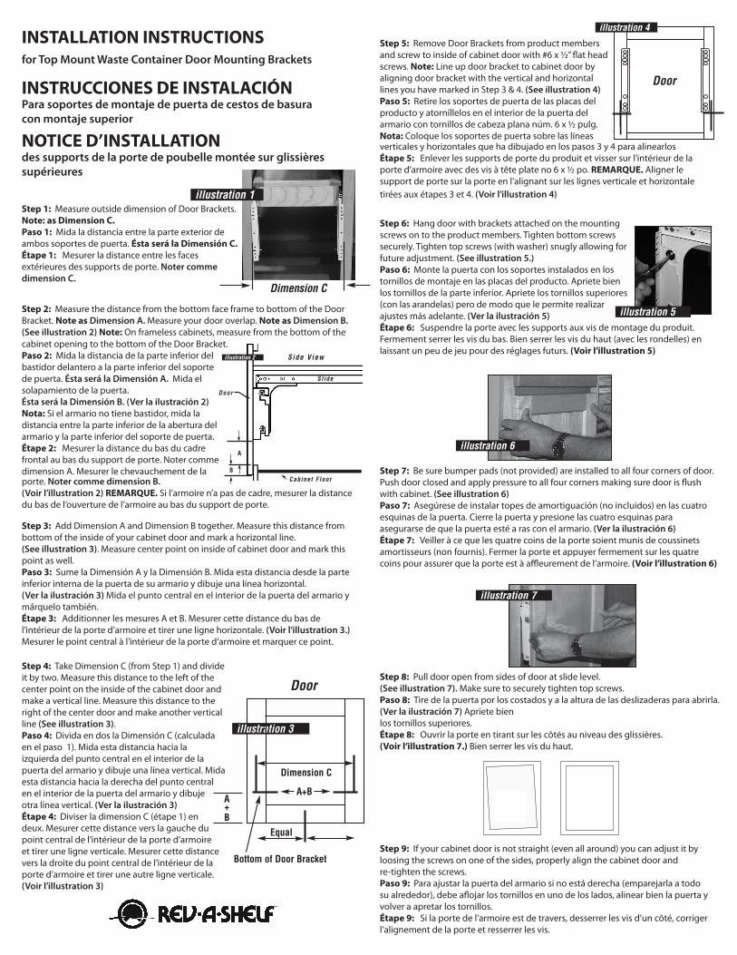
Step 7: Be sure bumper pads (not provided) are installed to all four corners of door. Push door closed and apply pressure to all four corners making sure door is flush with cabinet. (See illustration 6)Paso 7: Asegúrese de instalar topes de amortiguación (no incluidos) en las cuatro esquinas de la puerta. Cierre la puerta y presione las cuatro esquinas para asegurarse de que la puerta esté a ras con el armario. (Ver la ilustración 6)Étape 7: Veiller à ce que les quatre coins de la porte soient munis de coussinets amortisseurs (non fournis). Fermer la porte et appuyer fermement sur les quatre coins pour assurer que la porte est à affleurement de l’armoire. (Voir l’illustration 6)
Step 9: If your cabinet door is not straight (even all around) you can adjust it by loosing the screws on one of the sides, properly align the cabinet door and re-tighten the screws.Paso 9: Para ajustar la puerta del armario si no está derecha (emparejarla a todo su alrededor), debe aflojar los tornillos en uno de los lados, alinear bien la puerta y volver a apretar los tornillos.Étape 9: Si la porte de l’armoire est de travers, desserrer les vis d’un côté, corriger l’alignement de la porte et resserrer les vis.
STEP 4:Take Dimension C (from Step 1)and divide it by two. Measure this distance to the left of the center point on the inside of the cabinet door and make a vertical line. Measure this distance to the right of the center point on the inside ofthe cabinet door and make another vertical line(See illustration 3)
STEP 6:Hang door with brackets attached on themounting screws on to the product members. Tighten bottom screws securely. Tighten top screws (with washer)snugly allowing for future adjustment. (See illustration 5)
STEP 3:Add Dimension A and Dimension B together. Measure this distance from bottom of the inside of your cabinet door and mark a horizontal line.(See illustration 3). Measure center point on inside of cabinet doorand mark this point as well.
A+B
Dimension C
Equal
STEP 7:Be sure bumper pads (not provided) are installed toall four corners of door. Push door closed and applypressure to all four cornersmaking sure door is flush with cabinet. (See illustration 6).
STEP 8:Pull door open, fromsides of door at slide level. (See illustration 7). Securely tighten top screws.
STEP 9:If your cabinet door is not straight (even all around) you canadjust it by loosing the screws on one of the sides, properly align the cabinet door and re-tighten the screws.
illustration 5
illustration 3
illustration 6
illustration 7
Door...crookedall around
Door...straightafteradjustment
Door
Door
STEP 2:Measure the distance from the bottom faceframe to bottom of the Door Bracket. Note asDimension A. Measure your door overlap.Note as Dimension B.(See illustration 2) NOTE: On frameless cabinets measure fromthe bottom of the cabinet opening to the bottom of the Door Bracket.
illustration 2
A
B
Side View
Slide
Door
STEP 1:Measure outside to outside dimension of DoorBrackets.Note as Dimension C.
Dimension C
STEP 5:Remove Door Brackets fromproduct members and screw toinside of cabinet door with #6 x 1/2'' flat head screws.NOTE: Line up door bracket tocabinet door by aligning doorbracket with the vertical and horizontal lines you have markedin Steps 3 & 4. (See illustration4)
INSTALLATION INSTRUCTIONSFor Top Mount Waste Container DoorMounting Brackets
illustration 4
illustration 1
Cabinet Floor
A+B
Bottom of Door Bracket
Step 1: Measure outside dimension of Door Brackets. Note: as Dimension C.Paso 1: Mida la distancia entre la parte exterior de ambos soportes de puerta. Ésta será la Dimensión C.Étape 1: Mesurer la distance entre les faces extérieures des supports de porte. Noter comme dimension C.
Step 2: Measure the distance from the bottom face frame to bottom of the Door Bracket. Note as Dimension A. Measure your door overlap. Note as Dimension B. (See illustration 2) Note: On frameless cabinets, measure from the bottom of the cabinet opening to the bottom of the Door Bracket.Paso 2: Mida la distancia de la parte inferior del bastidor delantero a la parte inferior del soporte de puerta. Ésta será la Dimensión A. Mida el solapamiento de la puerta. Ésta será la Dimensión B. (Ver la ilustración 2) Nota: Si el armario no tiene bastidor, mida la distancia entre la parte inferior de la abertura del armario y la parte inferior del soporte de puerta.Étape 2: Mesurer la distance du bas du cadre frontal au bas du support de porte. Noter comme dimension A. Mesurer le chevauchement de la porte. Noter comme dimension B. (Voir l’illustration 2) REMARQUE. Si l’armoire n’a pas de cadre, mesurer la distance du bas de l’ouverture de l’armoire au bas du support de porte.STEP 4:
Take Dimension C (from Step 1)and divide it by two. Measure this distance to the left of the center point on the inside of the cabinet door and make a vertical line. Measure this distance to the right of the center point on the inside ofthe cabinet door and make another vertical line(See illustration 3)
STEP 6:Hang door with brackets attached on themounting screws on to the product members. Tighten bottom screws securely. Tighten top screws (with washer)snugly allowing for future adjustment. (See illustration 5)
STEP 3:Add Dimension A and Dimension B together. Measure this distance from bottom of the inside of your cabinet door and mark a horizontal line.(See illustration 3). Measure center point on inside of cabinet doorand mark this point as well.
A+B
Dimension C
Equal
STEP 7:Be sure bumper pads (not provided) are installed toall four corners of door. Push door closed and applypressure to all four cornersmaking sure door is flush with cabinet. (See illustration 6).
STEP 8:Pull door open, fromsides of door at slide level. (See illustration 7). Securely tighten top screws.
STEP 9:If your cabinet door is not straight (even all around) you canadjust it by loosing the screws on one of the sides, properly align the cabinet door and re-tighten the screws.
illustration 5
illustration 3
illustration 6
illustration 7
Door...crookedall around
Door...straightafteradjustment
Door
Door
STEP 2:Measure the distance from the bottom faceframe to bottom of the Door Bracket. Note asDimension A. Measure your door overlap.Note as Dimension B.(See illustration 2) NOTE: On frameless cabinets measure fromthe bottom of the cabinet opening to the bottom of the Door Bracket.
illustration 2
A
B
Side View
Slide
Door
STEP 1:Measure outside to outside dimension of DoorBrackets.Note as Dimension C.
Dimension C
STEP 5:Remove Door Brackets fromproduct members and screw toinside of cabinet door with #6 x 1/2'' flat head screws.NOTE: Line up door bracket tocabinet door by aligning doorbracket with the vertical and horizontal lines you have markedin Steps 3 & 4. (See illustration4)
INSTALLATION INSTRUCTIONSFor Top Mount Waste Container DoorMounting Brackets
illustration 4
illustration 1
Cabinet Floor
A+B
Bottom of Door Bracket
Step 5: Remove Door Brackets from product members and screw to inside of cabinet door with #6 x 1/2” flat head screws. Note: Line up door bracket to cabinet door by aligning door bracket with the vertical and horizontal lines you have marked in Step 3 & 4. (See illustration 4)Paso 5: Retire los soportes de puerta de las placas del producto y atorníllelos en el interior de la puerta del armario con tornillos de cabeza plana núm. 6 x 1/2 pulg. Nota: Coloque los soportes de puerta sobre las líneas verticales y horizontales que ha dibujado en los pasos 3 y 4 para alinearlos Étape 5: Enlever les supports de porte du produit et visser sur l’intérieur de la porte d’armoire avec des vis à tête plate no 6 x 1/2 po. REMARQUE. Aligner le support de porte sur la porte en l’alignant sur les lignes verticale et horizontale tirées aux étapes 3 et 4. (Voir l’illustration 4)
STEP 4:Take Dimension C (from Step 1)and divide it by two. Measure this distance to the left of the center point on the inside of the cabinet door and make a vertical line. Measure this distance to the right of the center point on the inside ofthe cabinet door and make another vertical line(See illustration 3)
STEP 6:Hang door with brackets attached on themounting screws on to the product members. Tighten bottom screws securely. Tighten top screws (with washer)snugly allowing for future adjustment. (See illustration 5)
STEP 3:Add Dimension A and Dimension B together. Measure this distance from bottom of the inside of your cabinet door and mark a horizontal line.(See illustration 3). Measure center point on inside of cabinet doorand mark this point as well.
A+B
Dimension C
Equal
STEP 7:Be sure bumper pads (not provided) are installed toall four corners of door. Push door closed and applypressure to all four cornersmaking sure door is flush with cabinet. (See illustration 6).
STEP 8:Pull door open, fromsides of door at slide level. (See illustration 7). Securely tighten top screws.
STEP 9:If your cabinet door is not straight (even all around) you canadjust it by loosing the screws on one of the sides, properly align the cabinet door and re-tighten the screws.
illustration 5
illustration 3
illustration 6
illustration 7
Door...crookedall around
Door...straightafteradjustment
Door
Door
STEP 2:Measure the distance from the bottom faceframe to bottom of the Door Bracket. Note asDimension A. Measure your door overlap.Note as Dimension B.(See illustration 2) NOTE: On frameless cabinets measure fromthe bottom of the cabinet opening to the bottom of the Door Bracket.
illustration 2
A
B
Side View
Slide
Door
STEP 1:Measure outside to outside dimension of DoorBrackets.Note as Dimension C.
Dimension C
STEP 5:Remove Door Brackets fromproduct members and screw toinside of cabinet door with #6 x 1/2'' flat head screws.NOTE: Line up door bracket tocabinet door by aligning doorbracket with the vertical and horizontal lines you have markedin Steps 3 & 4. (See illustration4)
INSTALLATION INSTRUCTIONSFor Top Mount Waste Container DoorMounting Brackets
illustration 4
illustration 1
Cabinet Floor
A+B
Bottom of Door Bracket
Step 6: Hang door with brackets attached on the mounting screws on to the product members. Tighten bottom screws securely. Tighten top screws (with washer) snugly allowing for future adjustment. (See illustration 5.)Paso 6: Monte la puerta con los soportes instalados en los tornillos de montaje en las placas del producto. Apriete bien los tornillos de la parte inferior. Apriete los tornillos superiores (con las arandelas) pero de modo que le permite realizar ajustes más adelante. (Ver la ilustración 5)Étape 6: Suspendre la porte avec les supports aux vis de montage du produit. Fermement serrer les vis du bas. Bien serrer les vis du haut (avec les rondelles) en laissant un peu de jeu pour des réglages futurs. (Voir l’illustration 5)
STEP 4:Take Dimension C (from Step 1)and divide it by two. Measure this distance to the left of the center point on the inside of the cabinet door and make a vertical line. Measure this distance to the right of the center point on the inside ofthe cabinet door and make another vertical line(See illustration 3)
STEP 6:Hang door with brackets attached on themounting screws on to the product members. Tighten bottom screws securely. Tighten top screws (with washer)snugly allowing for future adjustment. (See illustration 5)
STEP 3:Add Dimension A and Dimension B together. Measure this distance from bottom of the inside of your cabinet door and mark a horizontal line.(See illustration 3). Measure center point on inside of cabinet doorand mark this point as well.
A+B
Dimension C
Equal
STEP 7:Be sure bumper pads (not provided) are installed toall four corners of door. Push door closed and applypressure to all four cornersmaking sure door is flush with cabinet. (See illustration 6).
STEP 8:Pull door open, fromsides of door at slide level. (See illustration 7). Securely tighten top screws.
STEP 9:If your cabinet door is not straight (even all around) you canadjust it by loosing the screws on one of the sides, properly align the cabinet door and re-tighten the screws.
illustration 5
illustration 3
illustration 6
illustration 7
Door...crookedall around
Door...straightafteradjustment
Door
Door
STEP 2:Measure the distance from the bottom faceframe to bottom of the Door Bracket. Note asDimension A. Measure your door overlap.Note as Dimension B.(See illustration 2) NOTE: On frameless cabinets measure fromthe bottom of the cabinet opening to the bottom of the Door Bracket.
illustration 2
A
B
Side View
Slide
Door
STEP 1:Measure outside to outside dimension of DoorBrackets.Note as Dimension C.
Dimension C
STEP 5:Remove Door Brackets fromproduct members and screw toinside of cabinet door with #6 x 1/2'' flat head screws.NOTE: Line up door bracket tocabinet door by aligning doorbracket with the vertical and horizontal lines you have markedin Steps 3 & 4. (See illustration4)
INSTALLATION INSTRUCTIONSFor Top Mount Waste Container DoorMounting Brackets
illustration 4
illustration 1
Cabinet Floor
A+B
Bottom of Door Bracket
Step 8: Pull door open from sides of door at slide level.(See illustration 7). Make sure to securely tighten top screws.Paso 8: Tire de la puerta por los costados y a la altura de las deslizaderas para abrirla. (Ver la ilustración 7) Apriete bien los tornillos superiores.Étape 8: Ouvrir la porte en tirant sur les côtés au niveau des glissières. (Voir l’illustration 7.) Bien serrer les vis du haut.
INSTALLATION INSTRUCTIONS for Top Mount Waste Container Door Mounting Brackets
INSTRUCCIONES DE INSTALACIÓN Para soportes de montaje de puerta de cestos de basura con montaje superior
NOTICE D’INSTALLATION des supports de la porte de poubelle montée sur glissières supérieures
Step 4: Take Dimension C (from Step 1) and divide it by two. Measure this distance to the left of the center point on the inside of the cabinet door and make a vertical line. Measure this distance to the right of the center door and make another vertical line (See illustration 3).Paso 4: Divida en dos la Dimensión C (calculada en el paso 1). Mida esta distancia hacia la izquierda del punto central en el interior de la puerta del armario y dibuje una línea vertical. Mida esta distancia hacia la derecha del punto central en el interior de la puerta del armario y dibuje otra línea vertical. (Ver la ilustración 3)Étape 4: Diviser la dimension C (étape 1) en deux. Mesurer cette distance vers la gauche du point central de l’intérieur de la porte d’armoire et tirer une ligne verticale. Mesurer cette distance vers la droite du point central de l’intérieur de la porte d’armoire et tirer une autre ligne verticale. (Voir l’illustration 3)
STEP 4:Take Dimension C (from Step 1)and divide it by two. Measure this distance to the left of the center point on the inside of the cabinet door and make a vertical line. Measure this distance to the right of the center point on the inside ofthe cabinet door and make another vertical line(See illustration 3)
STEP 6:Hang door with brackets attached on themounting screws on to the product members. Tighten bottom screws securely. Tighten top screws (with washer)snugly allowing for future adjustment. (See illustration 5)
STEP 3:Add Dimension A and Dimension B together. Measure this distance from bottom of the inside of your cabinet door and mark a horizontal line.(See illustration 3). Measure center point on inside of cabinet doorand mark this point as well.
A+B
Dimension C
Equal
STEP 7:Be sure bumper pads (not provided) are installed toall four corners of door. Push door closed and applypressure to all four cornersmaking sure door is flush with cabinet. (See illustration 6).
STEP 8:Pull door open, fromsides of door at slide level. (See illustration 7). Securely tighten top screws.
STEP 9:If your cabinet door is not straight (even all around) you canadjust it by loosing the screws on one of the sides, properly align the cabinet door and re-tighten the screws.
illustration 5
illustration 3
illustration 6
illustration 7
Door...crookedall around
Door...straightafteradjustment
Door
Door
STEP 2:Measure the distance from the bottom faceframe to bottom of the Door Bracket. Note asDimension A. Measure your door overlap.Note as Dimension B.(See illustration 2) NOTE: On frameless cabinets measure fromthe bottom of the cabinet opening to the bottom of the Door Bracket.
illustration 2
A
B
Side View
Slide
Door
STEP 1:Measure outside to outside dimension of DoorBrackets.Note as Dimension C.
Dimension C
STEP 5:Remove Door Brackets fromproduct members and screw toinside of cabinet door with #6 x 1/2'' flat head screws.NOTE: Line up door bracket tocabinet door by aligning doorbracket with the vertical and horizontal lines you have markedin Steps 3 & 4. (See illustration4)
INSTALLATION INSTRUCTIONSFor Top Mount Waste Container DoorMounting Brackets
illustration 4
illustration 1
Cabinet Floor
A+B
Bottom of Door Bracket