installation instructions for part 99-7612content.abt.com/documents/46904/997612a_install.pdf ·...
TRANSCRIPT

INSTALLATION INSTRUCTIONS FOR PART 99-7612
APPLICATIONS
METRA. The World’s best kits.™ metraonline.com1-800-221-0932 © COPYRIGHT 2004-2011 METRA ELECTRONICS CORPORATION
REV.
1/3
1/20
13
INST
99-7
612
CAUTION: Metra recommends disconnecting the negative battery terminal before beginning any installation. All accessories, switches, and especially air bag indicator lights must be plugged in before reconnecting the battery or cycling the ignition.
NOTE: Refer to the instructions included with the aftermarket radio.
Table of Contents
• ISO DIN radio provision with pocket• DDIN radio provisions• 7612A-Coated with Brushed Aluminum look• 7612B-Painted Matte Black
• A) Radio Housing • B) Radio Housing Brackets • C) Pocket • D) (14) #8 x 3/8” Phillips screws • E) (2) #8 x 1/2” Phillips screws • F) 7612 wire harness
KIT FEATURES
KIT COMPONENTS
WIRING & ANTENNA CONNECTIONS (sold separately)Wiring Harness: • 70-7550 1995-Up Nissan Harness • 70-7551 1995-Up Nissan Amp Integration HarnessAntenna Adapter: • 40-NI10 Nissan Antenna Adapter
• Panel removal tool • Phillips screwdriver • Socket WrenchTOOLS REQUIRED
Nissan Murano 2003-200799-7612A, 99-7612B
A B C D E F
Dash Disassembly
– Nissan Murano 2003-2007 ...............................2-3
Kit Assembly
– ISO DIN radio provision with pocket ...................3-4
– DDIN radio provision .........................................4-5
Wiring Instructions ................................................ 5

99-7612
1. Unclip and remove the trim panel surrounding the display and including the a/c vents. (Figure A)
2. Remove (2) Phillips screws exposed behind vent/display trim panel. b(Figure B)
3. Unclip and remove the lower trim panel around the bottom of the radio panel. (Figure C)
Continued on next page
Dash Disassembly
(Figure A)
(Figure D)
(Figure B)
(Figure E)
(Figure C) (Figure F)
2
4. Remove (1) Phillips screw per side of radio chassis exposed behind lower trim panel. (Figure D)
5. Remove radio/climate control assembly from the sub dash.
6. Remove (4) Phillips screws securing the radio chassis to the factory radio trim panel. Lift up slightly and proceed to step 7. (Figure E)
7. Unlock the connector on the switch panel and remove the cable joining the chassis and switch panel. (Figure F)
Continued on next pageLeft side
Right side
99-7612
Dash Disassembly Kit Assembly
(Figure B)
(Figure A)
(Figure C)
(Figure G)
(Figure H)
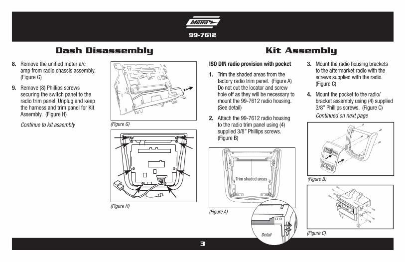
ISO DIN radio provision with pocket
1. Trim the shaded areas from the factory radio trim panel. (Figure A) Do not cut the locator and screw hole off as they will be necessary to mount the 99-7612 radio housing. (See detail)
2. Attach the 99-7612 radio housing to the radio trim panel using (4) supplied 3/8” Phillips screws. (Figure B)
3
8. Remove the unified meter a/c amp from radio chassis assembly. (Figure G)
9. Remove (8) Phillips screws securing the switch panel to the radio trim panel. Unplug and keep the harness and trim panel for Kit Assembly. (Figure H)
Continue to kit assembly
Trim shaded areas
Detail
3. Mount the radio housing brackets to the aftermarket radio with the screws supplied with the radio. (Figure C)
4. Mount the pocket to the radio/bracket assembly using (4) supplied 3/8” Phillips screws. (Figure C)
Continued on next page

99-7612
ISO DIN radio provision with pocket (continued)
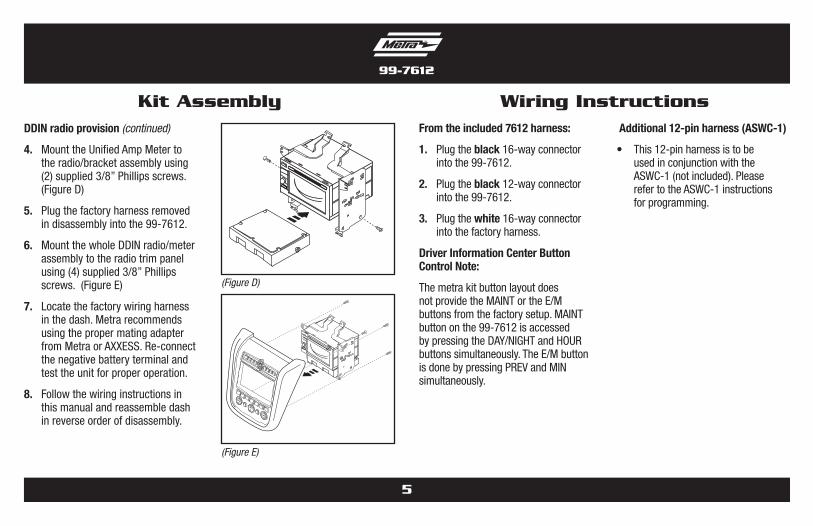
5. Mount the Unified Amp Meter to the radio/bracket assembly using (2) supplied 3/8” Phillips screws. (Figure D)
6. Plug the factory harness removed in disassembly into the 99-7612.
7. Mount the whole radio/pocket/meter assembly to the radio trim panel using (4) supplied 3/8” Phillips screws. (Figure E)
8. Locate the factory wiring harness and antenna plug in the dash. Metra recommends using the proper mating adapters from Metra and/or AXXESS.
9. Follow the wiring instructions in this manual and reassemble dash in reverse order of disassembly.
Kit Assembly
(Figure D)
(Figure E)
4
DDIN radio provision
1. Trim the shaded areas from the factory radio trim panel. (Figure A) Do not cut the locator and screw hole off as they will be necessary to mount the 99-7612 radio housing. (See detail)
2. Attach the 99-7612 radio housing to the radio trim panel using (4) supplied 3/8” Phillips screws. (Figure B)
(Figure B)
(Figure A)
(Figure C)
Trim shaded areas
Detail
3. Slide the Double DIN aftermarket radio into the radio housing brackets and secure with screws supplied with the radio. (Figure C)
Continued on next page
99-7612
DDIN radio provision (continued)
4. Mount the Unified Amp Meter to the radio/bracket assembly using (2) supplied 3/8” Phillips screws. (Figure D)
5. Plug the factory harness removed in disassembly into the 99-7612.
6. Mount the whole DDIN radio/meter assembly to the radio trim panel using (4) supplied 3/8” Phillips screws. (Figure E)
7. Locate the factory wiring harness in the dash. Metra recommends using the proper mating adapter from Metra or AXXESS. Re-connect the negative battery terminal and test the unit for proper operation.
8. Follow the wiring instructions in this manual and reassemble dash in reverse order of disassembly.
Kit Assembly Wiring Instructions
5
From the included 7612 harness:
1. Plug the black 16-way connector into the 99-7612.
2. Plug the black 12-way connector into the 99-7612.
3. Plug the white 16-way connector into the factory harness.
Driver Information Center Button Control Note:
The metra kit button layout does not provide the MAINT or the E/M buttons from the factory setup. MAINT button on the 99-7612 is accessed by pressing the DAY/NIGHT and HOUR buttons simultaneously. The E/M button is done by pressing PREV and MIN simultaneously.
(Figure D)
(Figure E)
Additional 12-pin harness (ASWC-1)
• This 12-pin harness is to be used in conjunction with the ASWC-1 (not included). Please refer to the ASWC-1 instructions for programming.

99-7612
Notes

99-7612
Notes

INSTALLATION INSTRUCTIONS FOR PART 99-7612
METRA. The World’s best kits.™ metraonline.com1-800-221-0932 © COPYRIGHT 2004-2011 METRA ELECTRONICS CORPORATION
REV.
1/3
1/20
13
INST
99-7
612
KNOWLEDGE IS POWEREnhance your installation and fabrication skills by enrolling in the most recognized and respected mobile electronics school in our industry.Log onto www.installerinstitute.com or call 800-354-6782 for more information and take steps toward a better tomorrow.
Metra recommends MECP certified technicians

INSTRUCCIONES DE INSTALACIÓN PARA LA PIEZA 99-7612
AplicAciones
METRA. The World’s best kits.™ metraonline.com1-800-221-0932 © COPYRIGHT 2004-2011 METRA ELECTRONICS CORPORATION
REV.
1/3
1/20
13
INST
99-7
612
PRECAUCIÓN: Metra recomienda desconectar el terminal negativo de la batería antes de comenzar cualquier instalación. Todos los accesorios, interruptores y, especialmente, las luces indicadoras de airbag deben estar enchufados antes de volver a conectar la batería o comenzar el ciclo de ignición.
Nota: Remítase a las instrucciones incluidas con el radio de posventa.
Indice
• Provisión de unidad central ISO DIN con cavidad• Provisiones de unidad central DDIN• 7612A - Recubierto con aspecto de aluminio cepillado• 7612B - Negro mate pintado
• A) Carcasa del radio • B) Soportes de carcasa del radio • C) Cavidad • D) (14) tornillos Phillips #8 x 3/8” • E) (2) tornillos #8 x 1/2” • F) Arnés de cables 7612
cArActerísticAs del kit
componentes del kit
cABleAdo Y coneXiones de AntenA (se venden por separado)
Arnés de cableado: • Arnés 70-7550 para Nissan 1995 y más recientes • Arnés 70-7551 para Nissan 1995 y más recientes con integración de amplificador
Adaptador de antena: • Adaptador de antena Nissan 40-NI10
• Herramienta para quitar paneles • Destornillador Phillips • Llave para dados
HerrAmientAs requeridAs
Nissan Murano 2003-200799-7612A, 99-7612B Desmontaje del tablero
– Nissan Murano 2003-2007 ...............................2-3
Ensamble del kit
– Provisiones de unidad central ISO DIN con cavidad .3-4
– Provisiones de unidad central DDIN ....................4-5
Instrucciones de conexiones de cables ................... 5
A B C D E F
99-7612
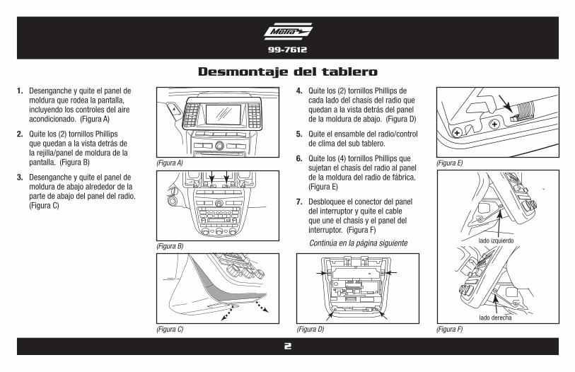
1. Desenganche y quite el panel de moldura que rodea la pantalla, incluyendo los controles del aire acondicionado. (Figura A)
2. Quite los (2) tornillos Phillips que quedan a la vista detrás de la rejilla/panel de moldura de la pantalla. (Figura B)
3. Desenganche y quite el panel de moldura de abajo alrededor de la parte de abajo del panel del radio. (Figura C)
Desmontaje del tablero
2
4. Quite los (2) tornillos Phillips de cada lado del chasís del radio que quedan a la vista detrás del panel de la moldura de abajo. (Figura D)
5. Quite el ensamble del radio/control de clima del sub tablero.
6. Quite los (4) tornillos Phillips que sujetan el chasís del radio al panel de la moldura del radio de fábrica. (Figura E)
7. Desbloquee el conector del panel del interruptor y quite el cable que une el chasís y el panel del interruptor. (Figura F)
Continúa en la página siguiente
(Figura A)
(Figura B)
(Figura C)
(Figura E)
(Figura F)
lado izquierdo
lado derecha
(Figura D)
99-7612
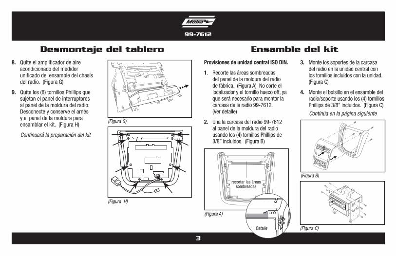
Desmontaje del tablero Ensamble del kit8. Quite el amplificador de aire
acondicionado del medidor unificado del ensamble del chasís del radio. (Figura G)
9. Quite los (8) tornillos Phillips que sujetan el panel de interruptores al panel de la moldura del radio. Desconecte y conserve el arnés y el panel de la moldura para ensamblar el kit. (Figura H)
Continuará la preparación del kit
3
(Figura G)
(Figura H)
(Figura B)
(Figura A)
(Figura C)Detalle
3. Monte los soportes de la carcasa del radio en la unidad central con los tornillos incluidos con la unidad. (Figura C)
4. Monte el bolsillo en el ensamble del radio/soporte usando los (4) tornillos Phillips de 3/8” incluidos. (Figura C)
Continúa en la página siguiente
Provisiones de unidad central ISO DIN.
1. Recorte las áreas sombreadas del panel de la moldura del radio de fábrica. (Figura A) No corte el localizador y el tornillo hueco off, ya que será necesario para montar la carcasa de la radio 99-7612. (Ver detalle)
2. Una la carcasa del radio 99-7612 al panel de la moldura del radio usando los (4) tornillos Phillips de 3/8” incluidos. (Figura B)
recortar las áreas sombreadas

99-7612
Provisiones de unidad central ISO DIN. (Continúa)
5. Monte el medidor amplificador unificado en el ensamble del radio/soporte usando los (2) tornillos Phillips de 3/8” incluidos. (Figura D)
6. Conecte el arnés de fábrica retirado durante el desensamble en el 99-7612.
7. Monte todo el ensamble del radio/bolsillo/medidor al panel de la moldura del radio usando los (4) tornillos Phillips de 3/8” incluidos. (Figura E)
8. Ubique el arnés de cableado de fábrica y el conector de la antena en el tablero. Metra recomienda el uso de adaptadores adecuados de acoplamiento de Metra y/o de AXXESS.
9. Siga las instrucciones de cableado de este manual y vuelva a armar el tablero al revés de como lo desarmó.
Ensamble del kit
(Figura D)
(Figura E)
(Figura B)
(Figura A)(Figura C)
Detalle
recortar las áreas sombreadas
Provisiones de unidad central DDIN.
1. Recorte las áreas sombreadas del panel de la moldura del radio de fábrica. (Figura A) No corte el localizador y el tornillo hueco off, ya que será necesario para montar la carcasa de la radio 99-7612. (Ver detalle)
2. Una la carcasa del radio 99-7612 al panel de la moldura del radio usando los (4) tornillos Phillips de 3/8” incluidos. (Figura B)
3. Deslice la unidad central doble DIN en los soportes de la carcasa del radio y sujete utilizando los tornillos suministrados con la unidad. (Figura C)
Continúa en la página siguiente
4
99-7612
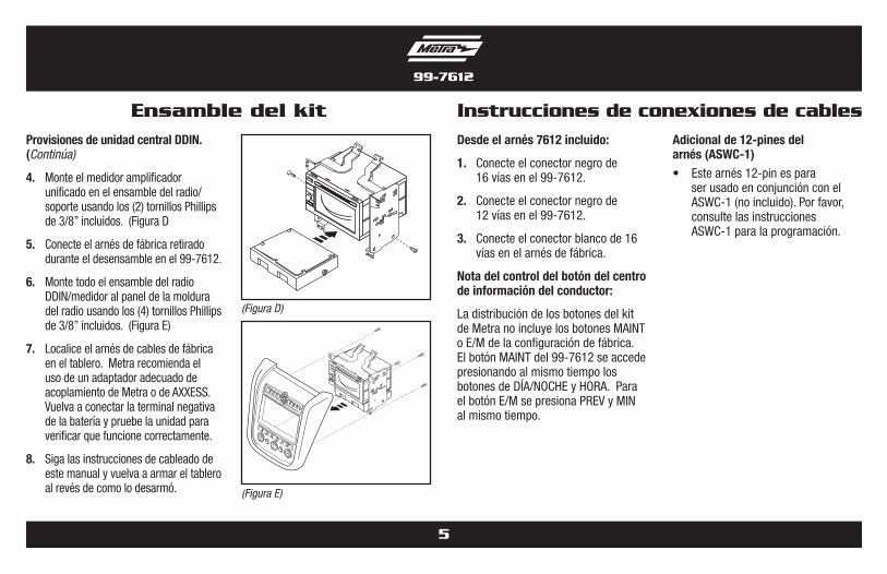
Provisiones de unidad central DDIN. (Continúa)
4. Monte el medidor amplificador unificado en el ensamble del radio/soporte usando los (2) tornillos Phillips de 3/8” incluidos. (Figura D
5. Conecte el arnés de fábrica retirado durante el desensamble en el 99-7612.
6. Monte todo el ensamble del radio DDIN/medidor al panel de la moldura del radio usando los (4) tornillos Phillips de 3/8” incluidos. (Figura E)
7. Localice el arnés de cables de fábrica en el tablero. Metra recomienda el uso de un adaptador adecuado de acoplamiento de Metra o de AXXESS. Vuelva a conectar la terminal negativa de la batería y pruebe la unidad para verificar que funcione correctamente.
8. Siga las instrucciones de cableado de este manual y vuelva a armar el tablero al revés de como lo desarmó.
Desde el arnés 7612 incluido:
1. Conecte el conector negro de 16 vías en el 99-7612.
2. Conecte el conector negro de 12 vías en el 99-7612.
3. Conecte el conector blanco de 16 vías en el arnés de fábrica.
Nota del control del botón del centro de información del conductor:
La distribución de los botones del kit de Metra no incluye los botones MAINT o E/M de la configuración de fábrica. El botón MAINT del 99-7612 se accede presionando al mismo tiempo los botones de DÍA/NOCHE y HORA. Para el botón E/M se presiona PREV y MIN al mismo tiempo.
Adicional de 12-pines del arnés (ASWC-1)• Este arnés 12-pin es para
ser usado en conjunción con el ASWC-1 (no incluido). Por favor, consulte las instrucciones ASWC-1 para la programación.
Ensamble del kit Instrucciones de conexiones de cables
(Figura D)
(Figura E)
5

99-7612
Notas
99-7612
Notas

INSTRUCCIONES DE INSTALACIÓN PARA LA PIEZA 99-7612
METRA. The World’s best kits.™ metraonline.com1-800-221-0932 © COPYRIGHT 2004-2011 METRA ELECTRONICS CORPORATION
REV.
1/3
1/20
13
INST
99-7
612
KNOWLEDGE IS POWEREnhance your installation and fabrication skills by enrolling in the most recognized and respected mobile electronics school in our industry.Log onto www.installerinstitute.com or call 800-354-6782 for more information and take steps toward a better tomorrow.
Metra recomienda técnicos con certificación del Programa de Certificación en Electrónica Móvil (Mobile Electronics Certification Program, MECP).
EL CONOCIMIENTO ES PODERMejore sus habilidades de instalación y fabricación inscribiéndose en la escuela de dispositivos electrónicos móviles más reconocida y respetada de nuestra industria. Regístrese en www.installerinstitute.com o llame al 800-354-6782 para obtener más información y avance hacia un futuro mejor.