installation instructions for hi-6s ignition 1 9000-6320 installation instructions for hi-6s...
TRANSCRIPT

5/11 9000-6320111
Installation Instructions for
HI-6S IGNITIONFor more information, see www.cranecams.com
CAUTION: READ INSTRUCTIONS CAREFULLY BEFORE STARTING INSTALLATION.
OVERVIEW - READ FIRST!!BeforeproceedingwiththeHI-6Sinstallation,readtheintro-ductorymaterialbelowandonpages2-4.ThenusetheAppli-cationsIndextofindtheappropriatesectionforyourvehicle.
INTRODUCTION CraneHI-6Spartnumber6000-6300isforgeneralpurposeapplicationsandincludesauniversaladapterharness.Partnumber 6000-6301 includes a plug-in adapter harness forFordTFI-IVapplications.Partnumber6000-6302includesaplug-inadapterharnessforlatemodelGMapplicationswithdualplugcoil.
The Crane HI-6S is amulti-spark inductive ignition spe-cially optimized for street driven performance vehicleswithanengine redlinebelow8,000RPM.ARISCmicro-controllermanagesallfunctionsoftheHI-6Sincludingthestagerev limiterandtimingretard functions. If rev limiterortimingretardfunctionsarenotrequired,theHI-6Salsohasananti-theftfunctionthatusesaswitchhiddenunderthedashtoselectaverylowrevlimittokeeptheenginefromstarting.
WhiletheHI-6Shasarangeofbuilt-inretardfunctionsinclud-ingboostproportionalretardusinganoptionalboostsensor(P/N 9000-0110), use of these built-in retard features pre-cludesuseofthebuilt-inrevlimiter.Ifanapplicationrequiresbothrevlimitingandretard,youwillrequiretheoptionalTRC-2TimingRetardControl(P/N6000-6425).Refertopage9.
Daytona Beach, FL 32117 | cranecams.com | 866-388-5120 | Fax 608-627-0480
TheHI-6Sisintendedforusewithvehiclesequippedwithoriginalequipment(OE)electronicignitionandcomputerenginecontrol.ItcanbedirectlytriggeredfromtheoutputoftheOEelectronicignitiononmost1981-95carsand1986-95lighttruckswithdis-tributorignitionandcomputerenginecontrol.Most1975to1980cars(1985forlighttrucks)usemagnetictriggerandwillrequiretheHI-6R(P/N6000-6400).TheHI-6Salsocanbeinstalledonpre-1975vehicleswithOEbreakerpointsbymeansofanopti-caltriggerconversion(refertoCranecatalogfordetails).CraneLX91 or PS-91 coils are recommended for optimum perfor-mance,however theHI-6S iscompatiblewithmostOEcoils.TheHI-6Sisnotcompatiblewithdistributorlessignitionsor1996andlatervehicleswithOBDIIOnBoardDiagnosticsystem.TheHI-6S is50states legal (CaliforniaAirResourcesBoardE.O.D-225-59)forvehicleswithoutOBDII.
INTELLIGENT MULTI-SPARK Multi-sparkisgeneratedbyrepeatedlyturningthecoilcurrentonandoffduring thesparksequence.At lowRPM,duringcranking,theHI-6Sgeneratesupto12sparks.Thisassuresquick starting even under themost adverse conditions.Atidle and cruise, the number of sparks fired is adjusted tomaintainatotalsparkdurationofabout20degrees(crank-shaft),assuringsmoothidle,improvedthrottleresponse,andeliminatingtheleansurgecharacteristicofsomelatemodelemission controlled vehicles. During acceleration at higherRPMlevels,theHI-6SgeneratesasinglepowerfulsparkwithabouttwicethesparkgapenergyofmostOEsystems(withuseofrecommendedLX-91orPS-91coil).
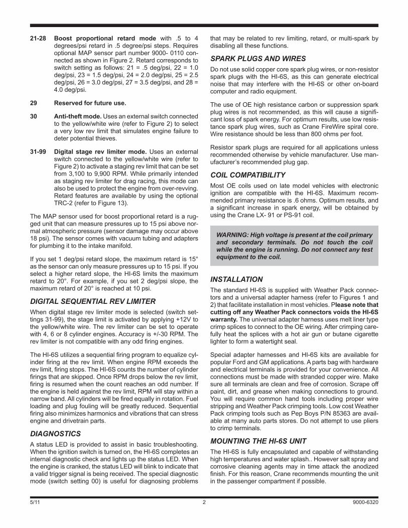
SWITCH SELECTABLE RETARD AND REV LIMIT MODES Two rotary switches shown in Figure 1 are used to selecttheoperatingmodes.PleasenotetheHI-6Sonlyreadstheswitcheswhentheignitionkeyisfirstturnedon.Ifyouchangeswitch settings, youmust cycle the ignition key off and onagaininorderfortheunittoreadthenewsettings.Modesarebasedonswitchsettingsasfollows:
00 Diagnostic mode. Disablesall rev limitandretardfunctions.Alsodisablesmulti-spark.
01-20 Digital retard modewith1to20degreesretardacti-vatedbyanexternalswitchconnectedtotheyellow/whitewire(refer toFigure2).Retardvaluedirectlycorrespondstoswitchsetting(i.e.04=4degrees)
APPLICATIONS INDEX All except Ford, GM, and Honda .......................Page 3 (most1981–95carsand1986–95lighttruckswithOEelectronic ignition and engine control computer and1972–86Moparwith4or5pinmodule)
Ford .....................................................................Page 5 (withDurasparkorTFI-IVelectronicignition)
GM .......................................................................Page 5 (with computerenginecontrol andCoil-In-Cap,dualplugexternalcoil,orLT-1stylecoil)
Honda and Acura Integra ..................................Page 5(withOEelectronicignitionandexternalorinternalcoil)
5/11 9000-63202
thatmayberelatedtorev limiting,retard,ormulti-sparkbydisablingallthesefunctions.
SPARK PLUGS AND WIRES Donotusesolidcoppercoresparkplugwires,ornon-resistorspark plugswith theHI-6S, as this can generate electricalnoise that may interfere with the HI-6S or other on-boardcomputerandradioequipment.
TheuseofOEhighresistancecarbonorsuppressionsparkplugwiresisnotrecommended,asthiswillcauseasignifi-cantlossofsparkenergy.Foroptimumresults,uselowresis-tancesparkplugwires,suchasCraneFireWirespiralcore.Wireresistanceshouldbelessthan800ohmsperfoot.
Resistorsparkplugsarerequiredforallapplicationsunlessrecommendedotherwisebyvehiclemanufacturer.Useman-ufacturer’srecommendedpluggap.
COIL COMPATIBILITY MostOE coils used on latemodel vehicleswith electronicignition are compatible with the HI-6S. Maximum recom-mendedprimaryresistanceis.6ohms.Optimumresults,anda significant increase in spark energy, will be obtained byusingtheCraneLX-91orPS-91coil.
INSTALLATION ThestandardHI-6SissuppliedwithWeatherPackconnec-torsandauniversaladapterharness(refertoFigures1and2)thatfacilitateinstallationinmostvehicles.Please note that cutting off any Weather Pack connectors voids the HI-6S warranty. TheuniversaladapterharnessusesmeltlinertypecrimpsplicestoconnecttotheOEwiring.Aftercrimpingcare-fullyheat thespliceswithahotairgunorbutanecigarettelightertoformawatertightseal.
SpecialadapterharnessesandHI-6Skitsareavailable forpopularFordandGMapplications.Apartsbagwithhardwareandelectricalterminalsisprovidedforyourconvenience.Allconnectionsmustbemadewithstrandedcopperwire.Makesureallterminalsarecleanandfreeofcorrosion.Scrapeoffpaint,dirt,andgreasewhenmakingconnectionstoground.You will require common hand tools including proper wirestrippingandWeatherPackcrimpingtools.LowcostWeatherPackcrimpingtoolssuchasPepBoysP/N85363areavail-ableatmanyautopartsstores.Donotattempttouseplierstocrimpterminals.
MOUNTING THE HI-6S UNIT TheHI-6Sisfullyencapsulatedandcapableofwithstandinghightemperaturesandwatersplash..Howeversaltsprayandcorrosive cleaningagentsmay in timeattack theanodizedfinish.Forthisreason,Cranerecommendsmountingtheunitinthepassengercompartmentifpossible.
21-28 Boost proportional retard mode with .5 to 4degrees/psiretard in.5degree/psisteps.RequiresoptionalMAPsensorpartnumber9000-0110con-nectedasshowninFigure2.Retardcorrespondstoswitchsettingasfollows:21=.5deg/psi,22=1.0deg/psi,23=1.5deg/psi,24=2.0deg/psi,25=2.5deg/psi,26=3.0deg/psi,27=3.5deg/psi,and28=4.0deg/psi.
29 Reserved for future use.
30 Anti-theft mode. Usesanexternalswitchconnectedtotheyellow/whitewire(refertoFigure2)toselectavery lowrev limit thatsimulatesenginefailure todeterpotentialthieves.
31-99 Digital stage rev limiter mode. Usesanexternalswitch connected to the yellow/whitewire (refer toFigure2)toactivateastagingrevlimitthatcanbesetfrom3,100to9,900RPM.Whileprimarilyintendedasstagingrevlimiterfordragracing,thismodecanalsobeusedtoprotecttheenginefromover-revving.RetardfeaturesareavailablebyusingtheoptionalTRC-2(refertoFigure13).
TheMAPsensorusedforboostproportionalretardisarug-gedunitthatcanmeasurepressuresupto15psiabovenor-malatmosphericpressure(sensordamagemayoccurabove18psi).Thesensorcomeswithvacuumtubingandadaptersforplumbingittotheintakemanifold.
Ifyouset1deg/psiretardslope,themaximumretardis15°asthesensorcanonlymeasurepressuresupto15psi.Ifyouselectahigher retardslope, theHI-6S limits themaximumretard to 20°. For example, if you set 2 deg/psi slope, themaximumretardof20°isreachedat10psi.
DIGITAL SEQUENTIAL REV LIMITER Whendigitalstagerev limitermodeisselected(switchset-tings31-99),thestagelimitisactivatedbyapplying+12Vtotheyellow/whitewire.Therev limitercanbeset tooperatewith4,6or8cylinderengines.Accuracyis+/-30RPM.Therevlimiterisnotcompatiblewithanyoddfiringengines.
TheHI-6Sutilizesasequentialfiringprogramtoequalizecyl-inderfiringat therev limit.WhenengineRPMexceedstherevlimit,firingstops.TheHI-6Scountsthenumberofcylinderfiringsthatareskipped.OnceRPMdropsbelowtherevlimit,firingisresumedwhenthecountreachesanoddnumber.Iftheengineisheldagainsttherevlimit,RPMwillstaywithinanarrowband.Allcylinderswillbefiredequallyinrotation.Fuelloadingandplugfoulingwillbegreatlyreduced.Sequentialfiringalsominimizesharmonicsandvibrationsthatcanstressengineanddrivetrainparts.
DIAGNOSTICS AstatusLEDisprovidedtoassist inbasic troubleshooting.Whentheignitionswitchisturnedon,theHI-6ScompletesaninternaldiagnosticcheckandlightsupthestatusLED.Whentheengineiscranked,thestatusLEDwillblinktoindicatethatavalidtriggersignalisbeingreceived.Thespecialdiagnosticmode (switchsetting00) isuseful fordiagnosingproblems
WARNING: High voltage is present at the coil primary and secondary terminals. Do not touch the coil while the engine is running. Do not connect any test equipment to the coil.
5/11 9000-632033
Make sure that the HI-6S mounting location is away fromexhaustsystemheat,protectedfromsaltwatersplash,andhasgoodairflowforcooling(donotmountundercarpeting).Whenyouhavepickedamountinglocation,makesurethatthewireharnesswillreachandthattherotaryswitchesareaccessible.Atleasttwoscrewsshouldbeusedtosecuretheunit.
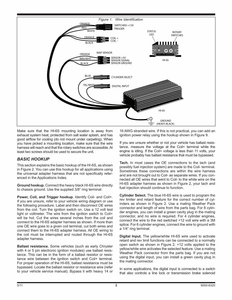
BASIC HOOKUP ThissectionexplainsthebasichookupoftheHI-6S,asshowninFigure2.Youcanusethishookupforallapplicationsusingtheuniversaladapterharnessthatarenotspecificallyrefer-encedintheApplicationsIndex.
Ground hookup.ConnecttheheavyblackHI-6Swiredirectlytochassisground.Usethesupplied3/8”ringterminal.
Power, Coil, and Trigger hookup. IdentifyCoil-andCoil+.Ifyouareunsure,refertoyourvehiclewiringdiagramorusethefollowingprocedure.LabelandthendisconnectOEwiresfromthecoil.Turntheignitionswitchon.Usea12volttestlightorvoltmeter.Thewirefromthe ignitionswitchtoCoil+will be hot.Cut thewires several inches from the coil andconnecttotheHI-6Sadapterharnessasshown.IfmorethanoneOEwiregoestoagivencoilterminal,cutbothwiresandconnectthemtotheHI-6Sadapterharness.AllOEwiringtothe coilmust be interrupted and routed through theHI-6Sadapterharness.
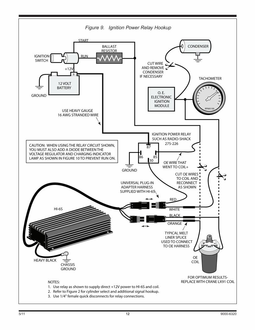
Ballast resistance. Somevehicles(suchasearlyChryslerwith4or5pinelectronicignitionmodules)useballastresis-tance.Thiscanbeintheformofaballastresistororresis-tancewire between the ignition switch andCoil+ terminal.ForproperoperationoftheHI-6S,ballastresistancemustbebypassed.Locatetheballastresistororresistancewire(refertoyourvehicleservicemanual).Bypassitwithheavy14or
16AWGstrandedwire.Ifthisisnotpractical,youcanaddanignitionpowerrelayusingthehookupshowninFigure9.
Ifyouareunsurewhetherornotyourvehiclehasballastresis-tance, measure the voltage at the Coil+ terminal while theengineisidling.IftheCoil+voltageislessthan11volts,yourvehicleprobablyhasballastresistancethatmustbebypassed.
Tach. Inmost cases theOE connections to the tach (andpossiblyfuelinjectionsystem)aremadetotheCoil-terminal.Sometimes these connections are within the wire harnessandarenotbroughtouttoCoil-asseparatewires.Ifyoucon-nectedallOEwiresthatwenttoCoil-tothewhitewireontheHI-6SadapterharnessasshowninFigure2,yourtachandfuelinjectionshouldcontinuetofunction.
Cylinder Select. TheblueHI-6Swireisusedtoprogramtherev limiterand retard feature for thecorrectnumberofcyl-inders as shown in Figure 2.Use amatingWeatherPackconnectorandlengthofwirefromthepartsbag.For8cylin-derengines,youcaninstallagreencavitypluginthematingconnector,andnowire is required.For4cylinderengines,connectthewiretotheredswitched+12voltwirewitha3Msplice.For6cylinderengines,connectthewiretogroundwitha1/4”ringterminal.
Digital Input. Theyellow/whiteHI-6Swireused toactivateretardandrevlimitfunctionscanbeconnectedtoanormallyopenswitchasshown inFigure2.+12voltsapplied to theyellow/whitewireactivatestheselectedfeature.UseamatingWeatherPackconnector fromthepartsbag. Ifyouarenotusingthedigitalinput,youcaninstallagreencavitypluginthematingconnector.
Insomeapplications,thedigitalinputisconnectedtoaswitchthat also controls a line lock or transmission brake solenoid
AB
A
B
A
BC
GROUND(HEAVY BLACK)
ROTARYSWITCHES
STATUSLED
HI-6S
HI-6S
056
4
9
1
7
3
8
2
056
4
9
1
7
3
8
2
056
4
9
1
7
3
8
2
STATUS RPM LIMIT X100
DIGITAL INPUTYEL/WHT
CYLINDER SELECT
MAP SENSOR
BLACK
BLACK
BLUE
BRN/WHT
ORANGE
SENSOR GROUNDSENSOR SIGNALSENSOR +5V
WHITERED
ORANGE
ORANGE
TRIGGERSWITCHED +12V
COIL -COIL +
Figure 1. Wire Identification
5/11 9000-632044
HI-6S
+
12 VOLTBATTERY
IGNITIONSWITCH
BALLASTRESISTOR
+12V
RUN
START
CUT WIREAND REMOVECONDENSER
IF NECESSARY TACHOMETER
RPMX100
GROUND
CONDENSER
+12V
INSTALL SUPPLIEDSURGE ABSORBER
IF SOLENOIDVALVE IS USED
GROUND
GROUND
OPTIONALMAP SENSORP/N 9000-0110FOR BOOST
PROPORTIONALRETARD
TYPICAL LINE LOCK ORTRANSMISSION BRAKESOLENOID VALVE USEDFOR STAGING ON SOME
DRAG RACING APPLICATIONS
OPTIONAL SWITCHFOR RETARD,ANTI-THEFT,
OR STAGE LIMIT
AB
HEAVY BLACKCHASSISGROUND
4 CYLINDERTO SWITCHED +12V
8 CYLINDERNO CONNECTION
6 CYLINDERGROUND
CYLINDERSELECT CYLINDER
SELECTHOOKUP
UNIVERSAL PLUG-INADAPTER HARNESS
SUPPLIED WITH HI-6S
O. E.ELECTRONIC
IGNITIONMODULE
A
BA
B
A
B
CUT OE WIRES TO COIL ANDRECONNECT AS SHOWN
+
OECOIL
BLUE
YELLOW/WHITE
BLACK
ORANGE
RED
WHITE
TYPICAL MELTLINER SPLICE
USED TO CONNECTTO OE HARNESS
BYPASS BALLASTRESISTOR WITH 14 AWG WIRE
Figure 2. Basic Hookup

5/11 9000-63205
GM VEHICLES NotethattheHI-6ScannotbeusedwithearlyGMvehicleswith4or5pinHEImodules(typically1974-1980modelyearsanddistributorwithvacuumadvance).GMHEIsystemswithvacuumadvancerequiretriggeringdirectlyfromthemagneticpickup.UsetheCraneHI-6RCDsystem(P/N6000-6400)fortheseearlyGMHEIapplications.
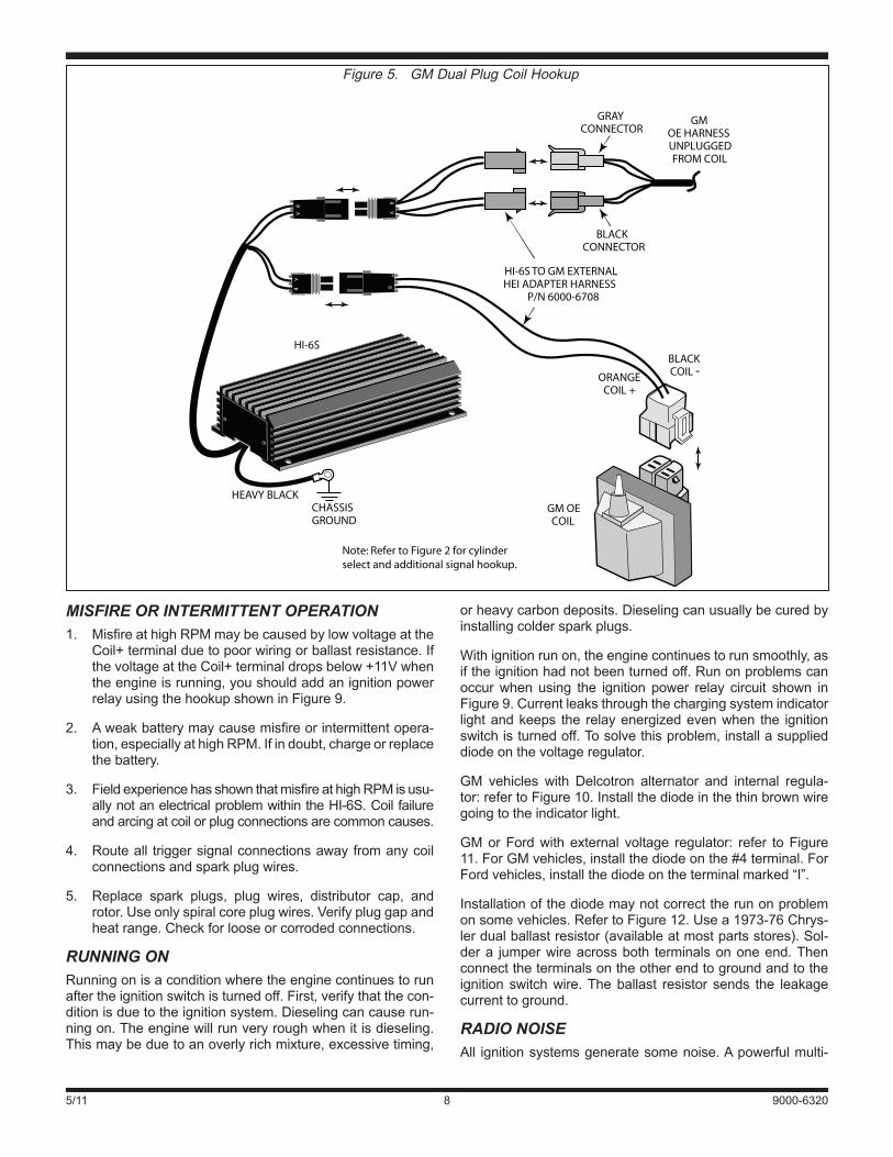
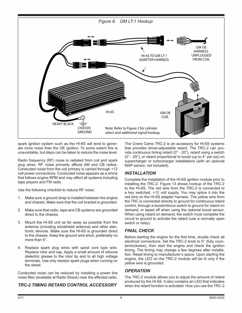
GMapplicationswillrequireanoptionaladapterharness.UseGMKitP/N6000-6302forDualPlugExternalCoil (Fig.5).Usetheadapterharnesstomakethepower,coil,andtriggerconnectionsasshowninFigures4-6.Thenfollowtheinstruc-tionsstartingonpage3andreferbacktoFigure2tohookupthegroundwire,cylinderselect,andanyrequireddigitalinputandMAPsensorconnections.
HONDA AND ACURA INTEGRA LatemodelHondaandAcuraIntegrahaveeitheradistributorwith internalcoiloranexternalcoil.TheOE internalcoil isnotsuitableforusewiththeHI-6SandmustbereplacedwithaCraneLX91orPS91. Internal coil distributorscaneasilybeconvertedtoexternalcoilbychangingthedistributorcap.Detailedinstructionsaregiveninthefollowingsections.
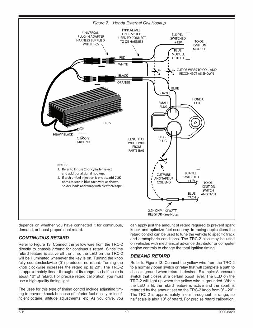
HONDA EXTERNAL COIL HOOKUP Use theuniversaladapterharnesssuppliedwith theHI-6SandthehookupshowninFigure7tomakethepower,coil,andtriggerconnections.Thenfollowtheinstructionsstartingonpage3andreferbacktoFigure2tohookupthegroundwire,cylinderselect,andanyrequireddigitalinputandMAPsensorconnections.
NotethatsomeHondaOEcoilshaveonlyasingleplug.Iden-tifywiresandconnectsimilartoFigure7.Switched+12VthatwenttoCoil+isconnectedtotheredHI-6SadapterharnesswireandthetriggersignalfromtheignitionmoduleandanytachwirethatwenttoCoil-areconnectedtothewhiteHI-6Sadapterharnesswire.
HONDA INTERNAL COIL CONVERSION RefertoFigure8.Youwillrequireanexternalcoildistributorcap.Craneoffersarangeofcapadapterstofitmost1988-2000models.TheCrane cap adapters are pre drilled andincludeallrequiredinstallationhardware.Checkourwebsiteforthemostuptodateapplicationsinformation.CraneP/N730-0694 covers the sameapplicationsasHondaOEP/N30102-PT3-A12.
Removethedistributorcapanddustshield.Youshouldkeepthedustshieldforhighboostturboapplicationsasitreducesthepossibilityofarcing.Youmayhavetomodifyittofitthenewcap.CarefullynotetheOEwiringwithinthedistributor.RemovetheOEcoil(heldinplacewithtwoscrews).Installa2positionterminalblockasshown.ThisissuppliedwiththeCraneadapterkitoryoucanuseRadio-ShackP/N274-656.Tiewraptheterminalblocktooneofthecoilmountingholesorfabricateasupportbracketfromaluminumchannelmate-rial.ConnecttheOEcoilwirestotheterminalblockasshown.
UsetheuniversaladapterharnesssuppliedwiththeHI-6SandthehookupshowninFigure8tomakethepower,coil,andtriggercon-
valve.Whentheswitchopensandcurrentflowtothesolenoidisinterrupted,electricaltransients(upto500volts)occur.Thesetransientscanleadtoglitchesinon-boardelectronics.Thesolu-tionistoinstallthesuppliedsurgeabsorber.Itwilllimitthemaxi-mumvoltagetoabout40volts.Thesurgeabsorberappearsasasmall1/2inchdiameterdiskwithtwowireleads.Solderoneleadtothestageswitchandtheotherleadtoaterminalthatcon-nectstogroundasshowninFigure2.
MAP Sensor/TRC-2 Input. TheHI-6Swireharness includesa3terminalWeatherPackconnectorthatdirectlyplugsintoanoptionalMAPsensorforboostproportionalretardasshowninFigure2.Youcanalsoconnectthebrown/whitewireonthiscon-nectortoanoptionalTRC-2TimingRetardControlasshowninFigure13.Ifyouarenotusingeitherofthesefeatures,tapeupthe3terminalconnectorinordertokeepmoistureout.
HOOKUP INSTRUCTIONS FOR SPECIFIC APPLICATIONS VEHICLES WITH HALL EFFECT SYSTEMS Manylatemodelvehicles,especiallyEuropeanvehicles,haveOEHall Effect ignition systems.Use the universal adapterharnesssuppliedwiththeHI-6SandthebasichookupshowninFigure2andexplainedstartingonpage3.TheHallEffectpickupcannotdirectlytriggertheHI-6S;theOEmodulemustbefunctioningcorrectlyandremaininstalled.
1972–86 MOPAR VEHICLES WITH 4 OR 5 PIN MODULES Use theuniversaladapterharnesssuppliedwith theHI-6SandthebasichookupshowninFigure2andexplainedstart-ingonpage3.AlltheseMoparvehicleshaveaceramicbal-lastresistormountedonthefirewall.Fourpinmodulesuseatwoterminalballastresistor.Youcanbypassthisresistorbysolderingallthewiresgoingtoittogether.Fivepinmodulesuseafourterminalballastresistor.Theballastresistoralsosuppliespowertothefivepinmodule.Bypassingtheresis-tormaydamagethemodule.YoumustusethepowerrelaycircuitshowninFigure9ifyourvehiclehasafivepinmodule.
FORD VEHICLES WITH TFI-IV ELECTRONIC IGNITION TheseapplicationswillrequireHI-6SFordkitP/N6000-6301.Usetheadapterharnesstomakethepower,coil,andtriggerconnectionsasshown inFigure3.Then follow the instruc-tionsstartingonpage3andreferbacktoFigure2tohookupthegroundwire,cylinderselect,andanyrequireddigitalinputandMAPsensorconnections.
FORD VEHICLES WITH DURASPARK ELECTRONIC IGNITION FordDuraspark applications require addition of an ignitionpower relayas theonlypracticalmeans tobypass theOEballast resistancewire. Use the universal adapter harnesssuppliedwiththeHI-6SandthepowerrelayhookupshowninFigure9tomakethepower,coil,andtriggerconnections.Thenfollowtheinstructionsstartingonpage3andreferbacktoFigure2 tohookupthegroundwire,cylinderselect,andanyrequireddigitalinputandMAPsensorconnections.

5/11 9000-63206
nections.Thenfollowtheinstructionsstartingonpage3andreferbacktoFigure2tohookupthegroundwire,cylinderselect,andanyrequireddigitalinputandMAPsensorconnections.
IfyoudidnotpurchaseaCraneadapterkit,youwillhavetofabricateahighvoltagecableforusebetweenthecoilandnewdistributorcap.
FINAL CHECK Beforestartingtheengineforthefirsttime,doublecheckallelectrical connections. Make sure you have set the rotaryswitches for the intendedoperatingmode.Start theengineandverifythattimingissettomanufacturer’sspecifications.
TROUBLESHOOTING HI-6S OPERATION Did the engine properly before installation of theHI-6S?Ifnot,youcaneasily reconnect theOE ignitionbyunplug-ging theHI-6S from theadapter harnessandplugging themaleandfemaleWeatherPackplugsontheadapterharnesstogether.This restores theOE connections.After restoringthe OE connections find and correct the original problem.TheHI-6SwillnotfunctioniftheOEmoduleisdefective.DidtheHI-6Sfunctioncorrectlybeforetheproblemoccurred?Iftheanswer isyes,didyouchangeanything thatmayhaveaffectedit?Ifyouconnectedanexternalcontrolorchangedignitioncoils,trygoingbacktothelastsetupthatworkedOKtohelpisolatetheproblem.
Iftheenginewillnotstart,orrunsroughorintermittently,fol-lowthecheckliststepsgiveninthefollowingsections.
NO STATUS LED WHEN IGNITION IS ON If thestatusLEDdoesn’t lightupaftertheignitionswitchisturnedon,checkpowerandgroundconnections.Useavoltmetertoverify+12voltsattheredHI-6SwireandtheCoil+terminal.Alsoverify+12voltswhentheignitionswitch is inthestartposition.Duringcranking,theHI-6Swillcontinuetooperatedowntoabout+5volts.
ENGINE WILL NOT START 1. If the status LED lights upwhen the ignition switch is
turnedonbuttheenginewillnotstart,verifythatthesta-tusLEDblinkswhiletheengineiscranking.
2. IfthestatusLEDdoesn’tblink,theHI-6Sisnotreceivingatriggersignal.Rechecktriggersignalelectricalconnec-tions(whitewire)andtriggersource.
3. IfthestatusLEDblinks,butenginewillnotstart,recheckcoil primary connections or replace coil.TheonlywiregoingtoCoil-shouldbetheblackHI-6Swire.Tachandfuel injection systemsmust be connected to thewhiteHI-6Striggerwire.Ifthehookupiscorrectandtheenginewill not start upon installation of anHI-6S system, thefuelinjectionmaynotbereceivingapropertriggersignal.PleasecallCraneTechSupportforfurtherassistance.
CHECKING FOR SPARK Tocranktheenginewithoutstartingortocheckforspark,useaKDToolstestplug.Makeupalengthofsparkplugwiretoconnectthetestplugtothecoil.
FORD OECOIL PLUG
(UNPLUGGEDFROM COIL)
RED / LIGHT GREEN
DARK GREEN / YELLOW
HI-6S
HEAVY BLACKCHASSISGROUND
TO FORDOE HARNESS
AB
A
BA
B
A
B
RED
WHITE
BLACK
ORANGE
FORDOE
COIL
Note: Refer to Figure 2 for cylinderselect and additional signal hookup.
HI-6S TOFORD TFI-IV
ADAPTER HARNESSP/N 6000-6707
Figure 3. Ford TFI-IV Hookup

5/11 9000-63207
BROWNBLACK
TO GMMODULE IN
DISTRIBUTOR PINK
GM HEAVYPINK WIRE
TO SWITCHED+12V
GM TACHWIRE
(BROWN)
RED+12V
WHITETACH
GMCONNECTORSUNPLUGGED
FROM HEI CAP
HI-6S
HEAVY BLACKCHASSISGROUND
AB
A
BA
B
A
B
CAUTION: USE THIS HOOKUP ONLY FOR 1981AND LATER GM MODELS WITH 7 PIN HEI MODULE(DISTRIBUTOR WITHOUT VACUUM ADVANCE)
GMPLUG
UNPLUGGEDFROM HEI
CAP
HI-6S TO GMCOIL-IN-CAP
HEI ADAPTER
Note: Refer to Figure 2 for cylinderselect and additional signal hookup.
Figure 4. GM Coil-In-Cap HEI Hookup
5/11 9000-63208
orheavycarbondeposits.Dieselingcanusuallybecuredbyinstallingcoldersparkplugs.
Withignitionrunon,theenginecontinuestorunsmoothly,asiftheignitionhadnotbeenturnedoff.Runonproblemscanoccurwhenusing the ignition power relay circuit shown inFigure9.Currentleaksthroughthechargingsystemindicatorlightandkeeps the relayenergizedevenwhen the ignitionswitchisturnedoff.Tosolvethisproblem,installasupplieddiodeonthevoltageregulator.
GM vehicles with Delcotron alternator and internal regula-tor:refertoFigure10.Installthediodeinthethinbrownwiregoingtotheindicatorlight.
GMorFordwithexternal voltage regulator: refer toFigure11.ForGMvehicles,installthediodeonthe#4terminal.ForFordvehicles,installthediodeontheterminalmarked“I”.
Installationofthediodemaynotcorrecttherunonproblemonsomevehicles.RefertoFigure12.Usea1973-76Chrys-lerdualballastresistor(availableatmostpartsstores).Sol-dera jumperwireacrossboth terminalsononeend.Thenconnecttheterminalsontheotherendtogroundandtotheignition switchwire.Theballast resistor sends the leakagecurrenttoground.
RADIO NOISE All ignitionsystemsgeneratesomenoise.Apowerfulmulti-
HI-6S
HEAVY BLACKCHASSISGROUND
AB
A
BA
B
A
B
ORANGECOIL +
BLACKCOIL -
GRAYCONNECTOR
BLACKCONNECTOR
GMOE HARNESSUNPLUGGEDFROM COIL
HI-6S TO GM EXTERNALHEI ADAPTER HARNESS
P/N 6000-6708
GM OECOIL
Note: Refer to Figure 2 for cylinderselect and additional signal hookup.
Figure 5. GM Dual Plug Coil Hookup
MISFIRE OR INTERMITTENT OPERATION 1. MisfireathighRPMmaybecausedbylowvoltageatthe
Coil+terminalduetopoorwiringorballastresistance.IfthevoltageattheCoil+terminaldropsbelow+11Vwhentheengineisrunning,youshouldaddanignitionpowerrelayusingthehookupshowninFigure9.
2. Aweakbatterymaycausemisfireorintermittentopera-tion,especiallyathighRPM.Ifindoubt,chargeorreplacethebattery.
3. FieldexperiencehasshownthatmisfireathighRPMisusu-allynotanelectricalproblemwithintheHI-6S.Coilfailureandarcingatcoilorplugconnectionsarecommoncauses.
4. Routeall triggersignalconnectionsawayfromanycoilconnectionsandsparkplugwires.
5. Replace spark plugs, plug wires, distributor cap, androtor.Useonlyspiralcoreplugwires.Verifypluggapandheatrange.Checkforlooseorcorrodedconnections.
RUNNING ON Runningonisaconditionwheretheenginecontinuestorunaftertheignitionswitchisturnedoff.First,verifythatthecon-ditionisduetotheignitionsystem.Dieselingcancauserun-ningon.Theenginewillrunveryroughwhenitisdieseling.Thismaybeduetoanoverlyrichmixture,excessivetiming,
5/11 9000-63209
TheCraneCamsTRC-2isanaccessoryforHI-6Ssystemsthat provides driver-adjustable retard.TheTRC-2 can pro-videcontinuoustimingretard(0°-20°),retardusingaswitch(0°-20°),orretardproportionaltoboost(upto4°perpsi)onsuperchargeror turbocharger installations (withanoptionalMAPsensor,notincluded).
INSTALLATION CompletetheinstallationoftheHI-6SignitionmodulepriortoinstallingtheTRC-2.Figure13showshookupoftheTRC-2to theHI-6S.Theredwire fromtheTRC-2 isconnected toa keyswitched,+12volt supply.Youmaysplice it into theredwireontheHI-6Sadapterharness.TheyellowwirefromtheTRCisconnecteddirectlytogroundforcontinuousretardcontrol,throughaboost/nitrousswitchtogroundforretardondemand,ortapedoffwhenusingtheoptionalboostsensor.Whenusingretardondemand,theswitchmustcompletethecircuittogroundtoactivatetheretard(useanormallyopenswitchorrelay).
FINAL CHECK Beforestartingtheengineforthefirsttime,doublecheckallelectricalconnections.SettheTRC-2knobto0°(fullycoun-terclockwise), then start the engine and check the ignitiontiming.Thetimingmaychangeafewdegreesafterinstalla-tion.Resettimingtomanufacturer’sspecs.Uponstartingtheengine, theLEDontheTRC-2modulewillbe litonly if theyellowwireisgrounded.
OPERATION TheTRC-2moduleallowsyoutoadjusttheamountofretardproducedbytheHI-6S.ItalsocontainsanLEDthatindicateswhentheretardfunctionisactivated.HowyouusetheTRC-2
spark ignitionsystemsuchas theHI-6Swill tend togener-atemorenoisethantheOEignition.Tosomeextentthisisunavoidable,butstepscanbetakentoreducethenoiselevel.
Radio frequency(RF)noise is radiated fromcoilandsparkplug wires. RF noise primarily affectsAM and CB radios.Conductednoisefromthecoilprimaryiscarriedthrough+12voltpowerconnections.ConductednoiseappearsasawhinethatfollowsengineRPMandmayaffectallsystemsincludingtapeplayersandFMradio.
UsethefollowingchecklisttoreduceRFnoise:
1. Makesureagroundstrapisinstalledbetweentheengineandchassis.Makesurethatthecoilbracketisgrounded.
2 Makesurethatradio,tapeandCBsystemsaregroundeddirecttothechassis.
3. Mount theHI-6Sunitas farawayaspossible fromtheantenna(includingwindshieldantenna)andotherelec-tronicdevices.MakesuretheHI-6S isgroundeddirecttothechassis.Keepthegroundwireshort,preferablynomorethan6”.
4. Replace spark plug wires with spiral core type wire.Replacerotorandcap.Applyasmallamountofsiliconedielectricgrease to the rotor tipand toallhighvoltageterminals.Useonlyresistorsparkplugswhenrunningonthestreet.
Conductednoisecanbereducedby installingapower linenoisefilter(availableatRadioShack)neartheaffectedradio.
TRC-2 TIMING RETARD CONTROL ACCESSORY
HI-6S
HEAVY BLACKCHASSISGROUND
AB
A
BA
B
A
B
GM OEHARNESS
UNPLUGGEDFROM COIL
HI-6S TO GM LT-1 ADAPTER HARNESS
GM OECOIL
Note: Refer to Figure 2 for cylinderselect and additional signal hookup.
Figure 6. GM LT-1 Hookup
5/11 9000-632010
canapplyjusttheamountofretardrequiredtopreventsparkknockandoptimizefueleconomy.Inracingapplicationstheretardcontrolcanbeusedtotunethevehicletospecifictrackandatmosphericconditions.TheTRC-2alsomaybeusedonvehicleswithmechanicaladvancedistributororcomputerenginecontrolstochangethetotalignitiontiming.
DEMAND RETARDRefertoFigure13.ConnecttheyellowwirefromtheTRC-2toanormallyopenswitchorrelaythatwillcompleteapathtochassisgroundwhenretardisdesired.Example:Apressureswitch thatclosesatacertainboost level.TheLEDontheTRC-2willlightupwhentheyellowwireisgrounded.WhentheLED is lit, the retard feature is active and the spark isretardedbytheamountsetontheTRC-2knobfrom0°-20°.TheTRC-2 isapproximately linear throughout its range,sohalfscaleisabut10°ofretard.Forpreciseretardcalibration,
dependsonwhetheryouhaveconnected it forcontinuous,demand,orboost-proportionalretard.
CONTINUOUS RETARDRefertoFigure13.ConnecttheyellowwirefromtheTRC-2directly to chassis ground for continuous retard. Since theretard feature isactiveall the time, theLEDon theTRC-2willbeilluminatedwheneverthekeyison.Turningtheknobfully counterclockwise (0°) producesno retard.Turning theknobclockwise increases the retardup to20°.TheTRC-2isapproximatelylinearthroughoutitsrange,sohalfscaleisabout10°ofretard.Forpreciseretardcalibration,youmustuseahigh-qualitytiminglight.
Theusesforthistypeoftimingcontrolincludeadjustingtim-ingtopreventknockbecauseofinferiorfuelqualityorinsuf-ficient octane, altitude adjustments, etc.As you drive, you
10
BLUEMODULEOUTPUT
TO OEIGNITIONMODULE
TO OEIGNITIONSWITCH
AND TACH
SMALLPLUG
LARGEPLUG
BLK-YELSWITCHED
+12V
BLK-YELSWITCHED
+12V
HI-6S
HEAVY BLACKCHASSISGROUND
AB
A
BA
B
A
B
HONDACOIL
UNIVERSALPLUG-IN ADAPTER
HARNESS SUPPLIEDWITH HI-6S
RED
WHITE
BLACK
ORANGE
LENGTH OFWHITE WIRE
FROMPARTS BAG
NOTES:1. Refer to Figure 2 for cylinder select and additional signal hookup.2. If tach or fuel injection is erratic, add 2.2K ohm resistor in blue tach wire as shown. Solder leads and wrap with electrical tape.
2.2K OHM 1/2 WATTRESISTOR - See Notes
CUT WIREAND TAPE UP
COIL END
BLUETACH
BLUEBLK/YEL
CUT OE WIRES TO COIL ANDRECONNECT AS SHOWN
TYPICAL MELTLINER SPLICE
USED TO CONNECTTO OE HARNESS
Figure 7. Honda External Coil Hookup

5/11 9000-63201111
HI-6S
HEAVY BLACKCHASSISGROUND
AB
A
BA
B
A
B
UNIVERSALPLUG-IN ADAPTER
HARNESS SUPPLIEDWITH HI-6S
RED
WHITE
BLACK
ORANGE
NOTES:1. Refer to Figure 2 for cylinder select and additional signal hookup.2. Remove internal coil, use LX91 coil and Honda cap 30102-PTS-A12 for external coil. Drill hole thru cap for HI-6S wire exit. See instructions for Honda cap conversion kits available from Crane.
TO OEHARNESS
TO OEHARNESS
TRIGGER(WAS COIL-) 2 POSITION
TERMINALBLOCK
+12V
+12V
RED+12V
TACHSIGNAL
MODULEOUTPUT(COIL-)
INPUT FROMECU
IGNITION MODULE
OE HOOKUP
OECOIL
+ -
DRILL 3/8" HOLE AND INSTALLRUBBER GROMMET FOR WIRE EXIT
HONDA30102-PTS A12 CAP
LX91COIL
TYPICAL MELTLINER SPLICE
ORANGECOIL+
BLACKCOIL-
USE PLUGSUPPLIEDWITH LX91
COIL-
Figure 8. HondaInternal Coil Hookup
5/11 9000-63201212
HI-6S
+
12 VOLTBATTERY
IGNITIONSWITCH
BALLASTRESISTOR
+12V
RUN
START
CUT WIREAND REMOVECONDENSER
IF NECESSARY TACHOMETER
RPMX100
GROUND
CONDENSER
AB
HEAVY BLACKCHASSISGROUND
GROUND
UNIVERSAL PLUG-INADAPTER HARNESS
SUPPLIED WITH HI-6S
O. E.ELECTRONIC
IGNITIONMODULE
A
BA
B
A
B
87
8630
85OE WIRE THAT
WENT TO COIL+
OECOIL
CAUTION: WHEN USING THE RELAY CIRCUIT SHOWN,YOU MUST ALSO ADD A DIODE BETWEEN THEVOLTAGE REGULATOR AND CHARGING INDICATORLAMP AS SHOWN IN FIGURE 10 TO PREVENT RUN ON.
USE HEAVY GAUGE16 AWG STRANDED WIRE
FOR OPTIMUM RESULTS-REPLACE WITH CRANE LX91 COILNOTES:
1. Use relay as shown to supply direct +12V power to HI-6S and coil.2. Refer to Figure 2 for cylinder select and additional signal hookup.3. Use 1/4" female quick disconnects for relay connections.
IGNITION POWER RELAYSUCH AS RADIO-SHACK
275-226
CUT OE WIRESTO COIL ANDRECONNECTAS SHOWN
TYPICAL MELTLINER SPLICE
USED TO CONNECTTO OE HARNESS
BLACK
ORANGE
RED
WHITE
Figure 9. Ignition Power Relay Hookup

5/11 9000-632013
youmustuseahigh-qualitytiminglight.ThediagraminFig-ure13showsanexamplewiththeknobsetfor10°ofretard.
Thistypeoftimingcontrolisgreatfornitrousoxideandsuper-chargedapplications,oranyvehiclethatrequiresadjustableretard.Fornitrousapplications,Figure13showshowanor-mally open relay is used to ground the yellow wire whennitrousandfuelsolenoidsareactivated.Thepinnumbersarefor a standard automotive relay such asRadioShackP/N275-226.Figure13alsoshowsapressureactivatedswitchdesignedtoretardtimingwhentheboostpressurereachesapre-setvalue.NAPABalkampofferstwoadjustablepressureswitches:P/N701-1591(3-7psigrange)andP/N701-1603(1.1-3psigrange).
Demandretardmodeisalsogreatforcrank-triggersystemswhereamomentarystartretardisrequired.Amanualswitchor a normally open relayenergizedby the starter solenoidcanbeusedtogroundtheyellowwireduringcrankingtopro-videupto20°ofstartingretard.Oncetheswitchisreleased,timingreturnstonormal.
BOOST PROPORTIONAL RETARDRefer to Figure 13. An optional MAP sensor (Crane P/N9000-0110) is required for boost proportional retard. Thissensorisaruggedunitthatcanmeasurepressuresupto15psiabovenormalatmosphericpressure.Thesensorcomeswithvacuumtubingandadaptersforplumbingittotheintakemanifold.TheyellowwirefromtheTRC-2shouldbetapedupwhenusingtheMAPsensor.
WhentheMAPsensorisconnected,theretardsettingontheTRC-2nowreferstoaretardslopefrom0°to4°perpsiofboost.Simplydividetheknobsettingby5todeterminetheretardslope(seeFigure13).Forexample,iftheknobissetto5°theretardslopeis1°perpsiandat5psiofboosttheretardis5°.Asboostrisesfurther,theretardincreasesatthissameslopeuptoamaximumof20°.Iftheboostlevelexceeds15psi,theretardlevelsoffasshowninFigure13(sensordam-agemayoccurabove18psi).
The status LED on the TRC-2 illuminates when retard isbeingapplied.Undermost conditions, thisoccursbetween0.5and1.0psiofboost.Asboostrises,retardriseswithaslopedeterminedby the knob setting.Note that the retardslopestopsrisingwhentheboostreaches15psiortheretardreaches20°.TheTRC-2 isapproximately linear throughoutitsrange,butforpreciseretardcalibrationuseatiminglighttoobtainretardvalue.
TROUBLESHOOTING Did theengine runproperlybefore installationof theTRC-2?Ifnot,removetheboththeTRC-2andHI-6Sunits,rein-stall theOE ignition or another known good unit and thenfindandcorrect theoriginalproblem.Makesure theHI-6Ssystem functions properly before installing or troubleshoot-ing theTRC-2accessory.Did theTRC-2 function correctlybefore theproblemoccurred?If theanswer isyes,didyouchangeanythingthatmayhaveaffectedit?Ifyouconnectedanexternalcontrolorchangedignitioncoils,trygoingbacktothelastsetupthatworkedtohelpisolatetheproblem.RefertotheHI-6Sinstallationinstructionsformoredetails,includ-
No. 2TERMINAL
BATTERMINAL
1973-83 GMDELCOTRON
No. 1TERMINAL
NOTE:USE BUTT SPLICES TO CONNECT DIODE, THEN WRAP WITH ELECTRICAL TAPE.
BROWN WIRETo No. 1 TERMINAL
INDICATORLAMP
1N4007 DIODE
TYPICAL BUTTSPLICE
Figure 10. Diode Installation on Delcotron Alternator
NOTE:USE BUTT SPLICES TO CONNECT DIODE, THEN WRAP WITH ELECTRICAL TAPE.
FORD VEHICLESATTACH DIODE TOTERMINAL MARKED "I"
EARLY GM VEHICLESATTACH DIODE TO TERMINAL MARKED "4"
1N4007 DIODE
INDICATORLAMP
VOLTAGEREGULATOR
TYPICAL BUTTSPLICE
Figure 11. Diode Installation on External Regulator
CHASSISGROUND
87
8630
85
JUMPERWIRE
IGNITIONSWITCH
CHRYSLER DUALBALLAST RESISTOR
CHASSISGROUND
TO BATTERY+
IGNITION POWER RELAYRADIO SHACK 275-226
+12V POWERTO COIL +AND HI-6S
Figure 12. Run-On Fix Using Chrysler Ballast Resistor
ingtheuseoftheHI-6Sbuilt-indiagnosticLEDlocatedontheignitionmodule.
Ifyouarenotgettingtheamountofretardyouexpect,checkthe LED on theTRC-2module; it lights upwhen retard isbeingapplied.Ifitdoesnotlightupincontinuousordemandretardmodes,checktheyellowwirefromtheTRC-2.Itmustcontactagoodchassisgroundwhenretardisneeded.Alsore-checkthebrown/whitewireconnectionfromtheTRC-2totheHI-6S.
Inboostretardmodetheamountofretardshouldbepropor-tionaltothepressuremeasuredbytheoptionalMAPsensor.Theamountofretardmayvaryinagivenapplicationiflocalatmospheric (barometric) pressure changes significantly.Thisoccursmostoftenwithachangeinaltitudeof1000feetormore.
IftheTRC-2settingsseemtobeoff,checkthetraveloftheknobfromno-retard(0°)tomaximum(20°).Makesurethatthepointerisproperlyalignedwhentheknobisateachlimit.

5/11 9000-63201414
HI-6S
CHASSISGROUND
REDSWITCHED
+12V
NITROUSSOLENOID
FUELSOLENOID
TO NITROUSTRIGGERCIRCUIT
8786
30
85
BOOST (PSI)
20
50
0 5 10 15 20 25MINMIN
MAX
MAX
KNOB AT 5
TIM
ING
RETA
RD
TIM
ING
RETA
RD TIM
ING
RETA
RD
20
10
0
KNOB AT 10
MIN
MAX
SWITCH OR RELAY ACTIVATED
20
10
0
KNOB AT 10
PRESSURESWITCH
NORMALLYOPENRELAY
CHASSISGROUND
GROUND
RETARD
TRC-2
OR OR
OR
TRC-2TIMING RETARD
CONTROL MODULE
TAPE UP WHENUSING BOOST
RETARD FEATURE
YELLOW WIRE FROM TRC-2 TIMING RETARD CONTROL
BLACK(GROUND)
BROWN / WHITE
CONTINUOUSRETARD
DEMAND RETARD
BOOST PROPORTIONALRETARD
Yellow wirepermanently
grounded Yellow wire groundedvia switch or relay
Optional MAP Sensor installed.Yellow wire taped up
CONNECT WITH3M INLINE SPLICE
A
BC
BLACK
ORANGE
BRN/WHT
Note: Remaining HI-6S Connections not shown forclarity. Refer to appropriate hookup diagrams.
CAUTION:SWITCHED +12V MUST BEHOT DURING START AND RUN
OPTIONALMAP SENSORP/N 9000-0110
Figure 13. TRC-2 Timing Retard Control Accessory Hookup