installation instructions for 45h & 47h mortise...
TRANSCRIPT
Installation Instructions for45H & 47H Mortise Locks
Ho , IN, B
Hol O/
A M(
†
ghr
B J ghr
C SD H
‡ 7Jy li
■
E Hm
F Et
G T( ■
H L ■
J Hm
†† ea
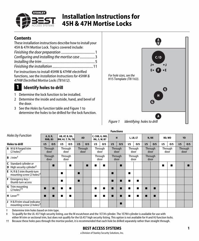
ContentsThese installation instructions describe how to install your 45H & 47H Mortise Lock. Topics covered include:Finishing the door preparation ...................................... 1Configuring and installing the mortise case ................. 3Installing the trim ............................................................ 5Finishing the installation ..............................................11For instructions to install 45HW & 47HW electrified functions, see the Installation Instructions for 45HW & 47HW Electrified Mortise Locks (T81612).
1 Identify holes to drill
1 Determine the lock function to be installed.2 Determine the inside and outside, hand, and bevel of
the door.3 See the Holes by Function table and Figure 1 to
determine the holes to be drilled for the lock function.
les by Function A, D, R, RHB, B5
AB, AT, B, BA, BW, HJ, T, TA, TD
ADC, CHB, G
INL, S, W
es to drill I/S O/S I/S O/S I/S O/S I/S
& N forged trim2 holes)†
Determine trim holes based on trim type.
Through door
Through door
Through door
Throudoo
trim† Through door
Through door
Throudoo
tandard cylinder or igh security cylinder‡
To qualify for the UL 437 high security listing, use the M escutcheon and the 1Eeither M trim or sectional trim, but does not qualify for the UL437 high securit
■ ■ ■ ■
, R & S trim thumb turn ounting screw (2 holes)† ■ ■
mergency key / humb turn access ■ ■
rim mounting 2 holes)†† ■ ■ ■ ■ ■
ever†† ■ ■ ■ ■ ■
& R trim visual indicator ounting screw (2 holes)†
Because these holes pass through the mortise pocket, it is recommended that
BEST ACCESSa Division of Stanley Sec
Figure 1 Identifying holes to drill
AB
C / D
FE
G
G
H
A
E
For hole sizes, see the H15 Template (T81163).
J J
Functions
D, 7
H L, LB, LT N, NX RD, WD YD
S I/S O/S I/S O/S I/S O/S I/S O/S I/S O/S
Through door
Through door
Through door
Through door
Through door
Through door
Through door
Through door
4 cylinder. The 1E7K4 cylinder is available for use withsting. This option is not available for H and HJ function locks.
■ ■ ■ ■
■ ■
■ ■ ■ ■
■ ■ ■ ■ ■ ■
■ ■ ■ ■ ■ ■
■
ch hole be drilled separately rather than straight through.
SYSTEMSurity Solutions, Inc.
1
Installation Instructions for 45H & 47H Mortise Locks
BEST ACCESSa Division of Stanley Se
Finishing the door preparation
2
Vertical centerline
of lever
HG
A
Horizontal centerline
of lock
G3/8 in
10 mm
7/8 in23 mm
3/8 in10 mm
5/8 in16 mmA
B
DC
1 3/4 in45 mm
1 1/4 in32 mm
E F1/8 in3 mm
1/2 in13 mm
E
Horizontal centerline
of lever
Align to edge of door.
Low edge (narrow side)
High edge (wide side)
Note: Use this template for the inside of
a LH or LHRB door or the outside
(keyed side) of a RH or RHRB door.
For metal doors, see the H16 Template—
Installation Specifications for 45H & 47H
Mortise Locks (T81166).
Str
ike
lip Hole Descriptions
A M & N forged
trim (2)
B J trim (1)
C Cylinder (1)
D High security
cylinder (1)
E H, R, & S trim
thumb turn
mounting screw (2)
F Emergency key /
thumb turn
access (1)
G Trim mounting (2)
H Lever (1)
J H & R trim
visual indicator
mounting screw (2)
J J 1/8 in3 mm
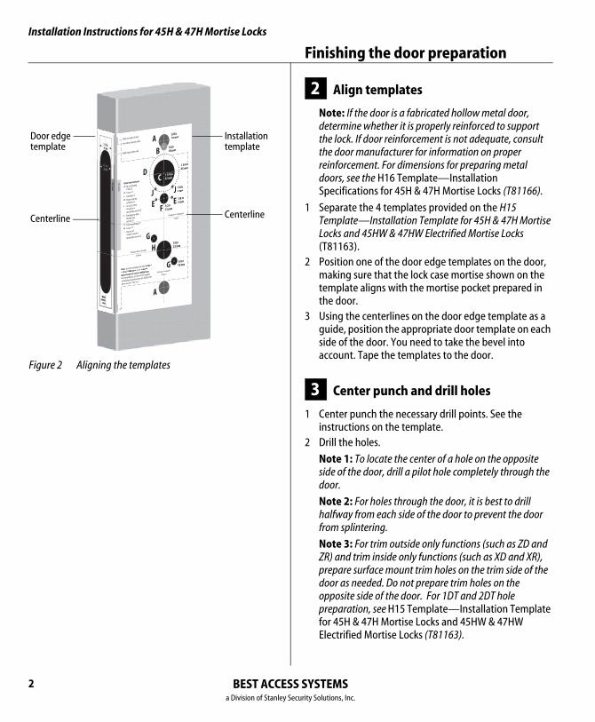
Figure 2 Aligning the templates
Installationtemplate
Door edgetemplate
CenterlineCenterline
2 Align templates
Note: If the door is a fabricated hollow metal door, determine whether it is properly reinforced to support the lock. If door reinforcement is not adequate, consult the door manufacturer for information on proper reinforcement. For dimensions for preparing metal doors, see the H16 Template—Installation Specifications for 45H & 47H Mortise Locks (T81166).
1 Separate the 4 templates provided on the H15 Template—Installation Template for 45H & 47H Mortise Locks and 45HW & 47HW Electrified Mortise Locks (T81163).
2 Position one of the door edge templates on the door, making sure that the lock case mortise shown on the template aligns with the mortise pocket prepared in the door.
3 Using the centerlines on the door edge template as a guide, position the appropriate door template on each side of the door. You need to take the bevel into account. Tape the templates to the door.
3 Center punch and drill holes
1 Center punch the necessary drill points. See the instructions on the template.
2 Drill the holes.
Note 1: To locate the center of a hole on the opposite side of the door, drill a pilot hole completely through the door.
Note 2: For holes through the door, it is best to drill halfway from each side of the door to prevent the door from splintering.
Note 3: For trim outside only functions (such as ZD and ZR) and trim inside only functions (such as XD and XR), prepare surface mount trim holes on the trim side of the door as needed. Do not prepare trim holes on the opposite side of the door. For 1DT and 2DT hole preparation, see H15 Template—Installation Template for 45H & 47H Mortise Locks and 45HW & 47HW Electrified Mortise Locks (T81163).
SYSTEMScurity Solutions, Inc.
Installation Instructions for 45H & 47H Mortise LocksInstallation Instructions for 45H & 47H Mortise Locks
Configuring & installing the mortise case
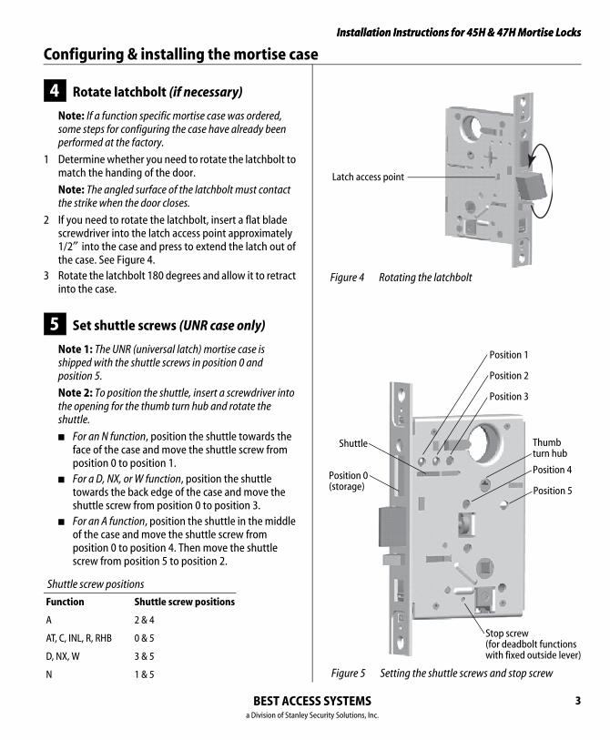
Figure 4 Rotating the latchbolt
Latch access point
Figure 5 Setting the shuttle screws and stop screw
Position 0(storage)
Position 1
Position 2
Position 3
Position 4
Position 5
Stop screw(for deadbolt functions with fixed outside lever)
Thumb turn hub
Shuttle
4 Rotate latchbolt (if necessary)
Note: If a function specific mortise case was ordered, some steps for configuring the case have already been performed at the factory.
1 Determine whether you need to rotate the latchbolt to match the handing of the door.
Note: The angled surface of the latchbolt must contact the strike when the door closes.
2 If you need to rotate the latchbolt, insert a flat blade screwdriver into the latch access point approximately 1/2″ into the case and press to extend the latch out of the case. See Figure 4.
3 Rotate the latchbolt 180 degrees and allow it to retract into the case.
5 Set shuttle screws (UNR case only)
Note 1: The UNR (universal latch) mortise case is shipped with the shuttle screws in position 0 and position 5.
Note 2: To position the shuttle, insert a screwdriver into the opening for the thumb turn hub and rotate the shuttle.
■ For an N function, position the shuttle towards the face of the case and move the shuttle screw from position 0 to position 1.
■ For a D, NX, or W function, position the shuttle towards the back edge of the case and move the shuttle screw from position 0 to position 3.
■ For an A function, position the shuttle in the middle of the case and move the shuttle screw from position 0 to position 4. Then move the shuttle screw from position 5 to position 2.
Shuttle screw positions
Function Shuttle screw positions
A 2 & 4
AT, C, INL, R, RHB 0 & 5
D, NX, W 3 & 5
N 1 & 5
BEST ACCESS SYSTEMSa Division of Stanley Security Solutions, Inc.
3
Installation Instructions for 45H & 47H Mortise Locks
BEST ACCESSa Division of Stanley Se
Configuring & installing the mortise case
4
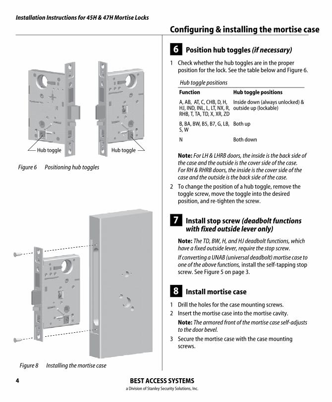
Figure 6 Positioning hub toggles
Hub toggleHub toggle
Figure 8 Installing the mortise case
6 Position hub toggles (if necessary)
1 Check whether the hub toggles are in the proper position for the lock. See the table below and Figure 6.
Note: For LH & LHRB doors, the inside is the back side of the case and the outside is the cover side of the case. For RH & RHRB doors, the inside is the cover side of the case and the outside is the back side of the case.
2 To change the position of a hub toggle, remove the toggle screw, move the toggle into the desired position, and re-tighten the screw.
7 Install stop screw (deadbolt functions with fixed outside lever only)
Note: The TD, BW, H, and HJ deadbolt functions, which have a fixed outside lever, require the stop screw.
If converting a UNAB (universal deadbolt) mortise case to one of the above functions, install the self-tapping stop screw. See Figure 5 on page 3.
8 Install mortise case
1 Drill the holes for the case mounting screws.2 Insert the mortise case into the mortise cavity.
Note: The armored front of the mortise case self-adjusts to the door bevel.
3 Secure the mortise case with the case mounting screws.
Hub toggle positions
Function Hub toggle positions
A, AB, AT, C, CHB, D, H, HJ, IND, INL, L, LT, NX, R, RHB, T, TA, TD, X, XR, ZD
Inside down (always unlocked) &outside up (lockable)
B, BA, BW, B5, B7, G, LB, S, W
Both up
N Both down
SYSTEMScurity Solutions, Inc.
Installation Instructions for 45H & 47H Mortise LocksInstallation Instructions for 45H & 47H Mortise Locks
Installing the trim
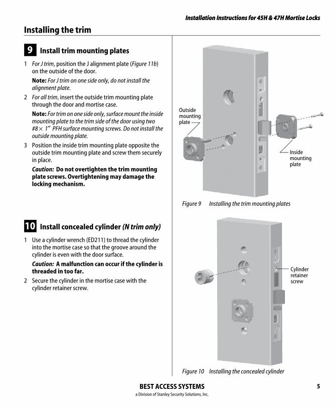
Figure 9 Installing the trim mounting plates
Outsidemountingplate
Insidemounting plate
Figure 10 Installing the concealed cylinder
Cylinderretainerscrew
9 Install trim mounting plates
1 For J trim, position the J alignment plate (Figure 11b) on the outside of the door.
Note: For J trim on one side only, do not install the alignment plate.
2 For all trim, insert the outside trim mounting plate through the door and mortise case.
Note: For trim on one side only, surface mount the inside mounting plate to the trim side of the door using two #8 × 1″ PFH surface mounting screws. Do not install the outside mounting plate.
3 Position the inside trim mounting plate opposite the outside trim mounting plate and screw them securely in place.
Caution: Do not overtighten the trim mounting plate screws. Overtightening may damage the locking mechanism.
10 Install concealed cylinder (N trim only)
1 Use a cylinder wrench (ED211) to thread the cylinder into the mortise case so that the groove around the cylinder is even with the door surface.
Caution: A malfunction can occur if the cylinder is threaded in too far.
2 Secure the cylinder in the mortise case with the cylinder retainer screw.
BEST ACCESS SYSTEMSa Division of Stanley Security Solutions, Inc.
5

Installation Instructions for 45H & 47H Mortise Locks
BEST ACCESSa Division of Stanley Se
Installing the trim
6
Figure 11a Installing the roses
Rose
Rosering
Figure 11b Installing the J trim escutcheons
Escutch
VIN dial
Alignment plate
Plastic spacer
11 Install roses or escutcheons
For sectional trim (Figure 11a)
1 Position the inside rose on the door so it is centered on the trim mounting plate.
2 Use the spanner wrench (KD316) to install the rose ring onto the inside mounting plate.
3 Position the outside rose on the door so it is centered on the trim mounting plate.
4 Use the spanner wrench to install the rose ring onto the outside mounting plate.
Note: For instructions for installing the visual indicator with sectional trim, see Task 13 on page 8.
For J trim (Figure 11b)
1 For H function locks, position the plastic spacer on the spindle of the visual indicator dial. With the deadbolt retracted, position the visual indicator (VIN) dial in the door with the text oriented at the top.
2 Position the inside escutcheon on the door so it is centered on the trim mounting plate. Install the escutcheon screw.
3 Use the spanner wrench (KD316) to install the trim ring onto the inside mounting plate.
4 Position the outside escutcheon on the door over the alignment plate.
5 Use the spanner wrench to install the trim ring onto the outside trim mounting plate.
Trim ring
Insideescutcheon
eon screw
SYSTEMScurity Solutions, Inc.
Installation Instructions for 45H & 47H Mortise LocksInstallation Instructions for 45H & 47H Mortise Locks
Installing the trim
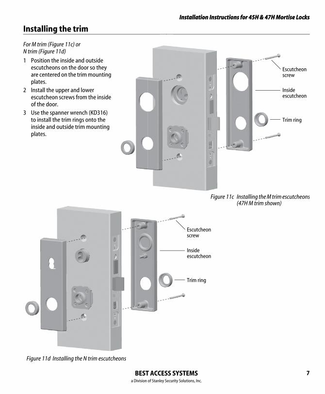
Figure 11c Installing the M trim escutcheons(47H M trim shown)
Escutcheonscrew
Insideescutcheon
Trim ring
Escutcheonscrew
Insideescutcheon
Trim ring
For M trim (Figure 11c) or N trim (Figure 11d)
1 Position the inside and outside escutcheons on the door so they are centered on the trim mounting plates.
2 Install the upper and lower escutcheon screws from the inside of the door.
3 Use the spanner wrench (KD316) to install the trim rings onto the inside and outside trim mounting plates.
Figure 11d Installing the N trim escutcheons
BEST ACCESS SYSTEMSa Division of Stanley Security Solutions, Inc.
7
Installation Instructions for 45H & 47H Mortise Locks
BEST ACCESSa Division of Stanley Se
Installing the trim
8
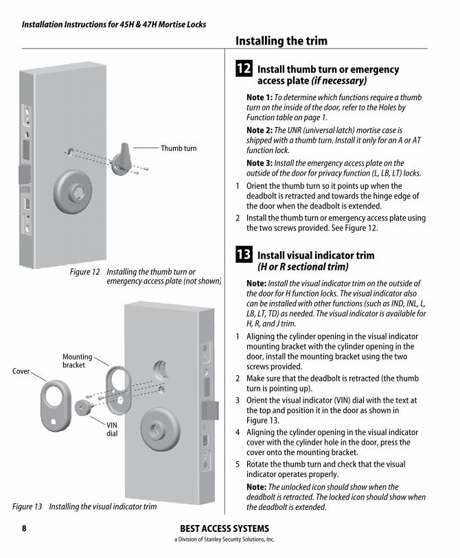
Figure 12 Installing the thumb turn or emergency access plate (not shown)
Thumb turn
Figure 13 Installing the visual indicator trim
Cover
Mounting bracket
VIN dial
12 Install thumb turn or emergency access plate (if necessary)
Note 1: To determine which functions require a thumb turn on the inside of the door, refer to the Holes by Function table on page 1.
Note 2: The UNR (universal latch) mortise case is shipped with a thumb turn. Install it only for an A or AT function lock.
Note 3: Install the emergency access plate on the outside of the door for privacy function (L, LB, LT) locks.
1 Orient the thumb turn so it points up when the deadbolt is retracted and towards the hinge edge of the door when the deadbolt is extended.
2 Install the thumb turn or emergency access plate using the two screws provided. See Figure 12.
13 Install visual indicator trim (H or R sectional trim)
Note: Install the visual indicator trim on the outside of the door for H function locks. The visual indicator also can be installed with other functions (such as IND, INL, L, LB, LT, TD) as needed. The visual indicator is available for H, R, and J trim.
1 Aligning the cylinder opening in the visual indicator mounting bracket with the cylinder opening in the door, install the mounting bracket using the two screws provided.
2 Make sure that the deadbolt is retracted (the thumb turn is pointing up).
3 Orient the visual indicator (VIN) dial with the text at the top and position it in the door as shown in Figure 13.
4 Aligning the cylinder opening in the visual indicator cover with the cylinder hole in the door, press the cover onto the mounting bracket.
5 Rotate the thumb turn and check that the visual indicator operates properly.
Note: The unlocked icon should show when the deadbolt is retracted. The locked icon should show when the deadbolt is extended.
SYSTEMScurity Solutions, Inc.
Installation Instructions for 45H & 47H Mortise LocksInstallation Instructions for 45H & 47H Mortise Locks
Installing the trim
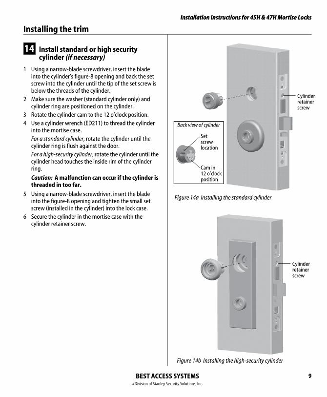
Figure 14a Installing the standard cylinder
Cylinderretainerscrew
Setscrewlocation
Cam in 12 o’clock position
Back view of cylinder
Figure 14b Installing the high-security cylinder
Cylinderretainerscrew
14 Install standard or high security cylinder (if necessary)
1 Using a narrow-blade screwdriver, insert the blade into the cylinder’s figure-8 opening and back the set screw into the cylinder until the tip of the set screw is below the threads of the cylinder.
2 Make sure the washer (standard cylinder only) and cylinder ring are positioned on the cylinder.
3 Rotate the cylinder cam to the 12 o’clock position.4 Use a cylinder wrench (ED211) to thread the cylinder
into the mortise case. For a standard cylinder, rotate the cylinder until the
cylinder ring is flush against the door. For a high-security cylinder, rotate the cylinder until the
cylinder head touches the inside rim of the cylinder ring.
Caution: A malfunction can occur if the cylinder is threaded in too far.
5 Using a narrow-blade screwdriver, insert the blade into the figure-8 opening and tighten the small set screw (installed in the cylinder) into the lock case.
6 Secure the cylinder in the mortise case with the cylinder retainer screw.
BEST ACCESS SYSTEMSa Division of Stanley Security Solutions, Inc.
9
Installation Instructions for 45H & 47H Mortise Locks
BEST ACCESSa Division of Stanley Se
Installing the trim
10
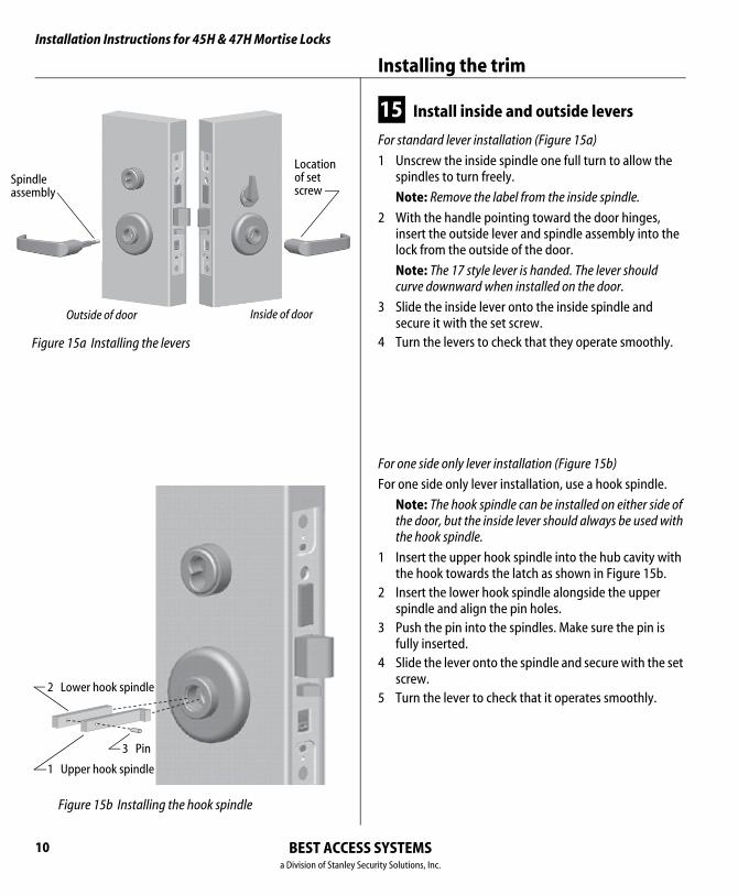
Figure 15a Installing the levers
Locationof setscrew
Outside of door Inside of door
Spindleassembly
Figure 15b Installing the hook spindle
1 Upper hook spindle
2 Lower hook spindle
3 Pin
15 Install inside and outside levers
For standard lever installation (Figure 15a)
1 Unscrew the inside spindle one full turn to allow the spindles to turn freely.
Note: Remove the label from the inside spindle.
2 With the handle pointing toward the door hinges, insert the outside lever and spindle assembly into the lock from the outside of the door.
Note: The 17 style lever is handed. The lever should curve downward when installed on the door.
3 Slide the inside lever onto the inside spindle and secure it with the set screw.
4 Turn the levers to check that they operate smoothly.
For one side only lever installation (Figure 15b)
For one side only lever installation, use a hook spindle.
Note: The hook spindle can be installed on either side of the door, but the inside lever should always be used with the hook spindle.
1 Insert the upper hook spindle into the hub cavity with the hook towards the latch as shown in Figure 15b.
2 Insert the lower hook spindle alongside the upper spindle and align the pin holes.
3 Push the pin into the spindles. Make sure the pin is fully inserted.
4 Slide the lever onto the spindle and secure with the set screw.
5 Turn the lever to check that it operates smoothly.
SYSTEMScurity Solutions, Inc.
Installation Instructions for 45H & 47H Mortise LocksInstallation Instructions for 45H & 47H Mortise Locks
Finishing the installation
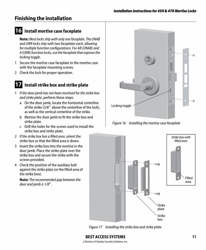
Figure 16 Installing the mortise case faceplate
Locking toggle
Installing the strike box and strike plate
Strikebox
Strikeplate
Filledarea
Strike box with filled area
16 Install mortise case faceplate
Note: Most locks ship with only one faceplate. The UNAB and UNR locks ship with two faceplates each, allowing for multiple function configurations. For AB (UNAB) and A (UNR) function locks, use the faceplate that exposes the locking toggle.
1 Secure the mortise case faceplate to the mortise case with the faceplate mounting screws.
2 Check the lock for proper operation.
17 Install strike box and strike plate
1 If the door jamb has not been mortised for the strike box and strike plate, perform these steps:a On the door jamb, locate the horizontal centerline
of the strike (3/8″ above the centerline of the lock), as well as the vertical centerline of the strike.
b Mortise the door jamb to fit the strike box and strike plate.
c Drill the holes for the screws used to install the strike box and strike plate.
2 If the strike box has a filled area, orient the strike box so that the filled area is down.
3 Insert the strike box into the mortise in the door jamb. Place the strike plate over the strike box and secure the strike with the screws provided.
4 Check the position of the auxiliary bolt against the strike plate (or the filled area of the strike box).
Note: The recommended gap between the door and jamb is 1/8″ .
Figure 17
BEST ACCESS SYSTEMSa Division of Stanley Security Solutions, Inc.
11
Installation Instructions for 45H & 47H Mortise Locks
BEST ACCESSa Division of Stanley Se
Finishing the installation
12
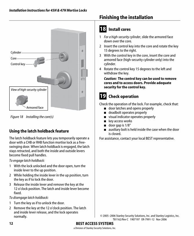
Figure 18 Installing the core(s)
Control key
Core
Cylinder
Armored face
View of high-security cylinder
Using the latch holdback feature
The latch holdback feature lets you temporarily operate a door with a CHB or RHB function mortise lock as a free-swinging door. When latch holdback is engaged, the latch stays retracted, and both the inside and outside levers become fixed pull handles.
To engage latch holdback:
1 With the lock unlocked and the door open, turn the inside lever to the up position.
2 While holding the inside lever in the up position, turn the key as if to lock the door.
3 Release the inside lever and remove the key at the 12 o’clock position. The latch and inside lever become fixed.
To disengage latch holdback:
1 Turn the key as if to unlock the door.2 Remove the key at the 12 o’clock position. The latch
and inside lever release, and the lock operates normally.
18 Install cores
1 For a high-security cylinder, slide the armored face down over the core.
2 Insert the control key into the core and rotate the key 15 degrees to the right.
3 With the control key in the core, insert the core and armored face (high-security cylinder only) into the cylinder.
4 Rotate the control key 15 degrees to the left and withdraw the key.
Caution: The control key can be used to remove cores and to access doors. Provide adequate security for the control key.
19 Check operation
Check the operation of the lock. For example, check that:■ door latches and opens properly■ deadbolt operates properly■ visual indicator operates properly■ key access works■ door gap is 1/8”■ auxiliary bolt is held inside the case when the door
is closed.For assistance, contact your local BEST representative.
© 2005–2006 Stanley Security Solutions, Inc. and Stanley Logistics, Inc.T81162/Rev C 1907197 ER-7991-12 Nov 2006
SYSTEMScurity Solutions, Inc.