installation instructions for 1997-2003 chevrolet c5 … 1. parts list lpe c5 corvette high flow...
TRANSCRIPT

Lingenfelter Performance Engineering1557 Winchester Road
Decatur, IN 46733(260) 724-2552
(260) 724-0422 faxwww.lingenfelter.com
Revision - 3.0 Release date 18 August 2016
Installation Instructions for1997-2003 Chevrolet C5 Corvette Lingenfelter High
Flow Fuel Pump Module
PN: L710650197

Page 1.
Parts ListLPE C5 Corvette High flow fuel pump module, L710650197
# Part number Description 1 31762 C5primaryfilterO-ring 1 31-56 C5inletgrommet 1 34869 Fuelplasticretainer 1 36469 Fuelreservoir 1 TI-125-156 Fuelfilter 1 TI-1250566 Secondaryfuelfilter 1 TI-GRJ420 Fuelpump 1 RXITWH-007 Fuelpumpwiringharness,internal 1 TI-32671-2 375mmconvolutedplastichose(installedonpump) 1 52545K45 Oetickerclamp 1 34872 Grommet 1 12459863 Fuelsenderseal 1 L920010000 LPEdecal 1 Instructions
• Vehicle lifting equipment (automotive lift or jack stands)• Wheel lug wrench or socket• Ratchet wrench• Torque wrench• 7 mm socket• 10 mm socket• 13 mm socket• Fuel line disconnect tool (for older models - available
from LPE, see below)
• Several shop towels• Scribe or small screwdriver• Three small screwdrivers• Oetiker pliers or side cutting pliers• Safety glasses• Fuel resistant gloves• Fire extinguisher
Additional Required Components•Fuel tank module seal kit (includes module bolts), PN 12459863 (AC Delco G25)
Optional Items• GM Quick Release fuel line tools, PN KMJ-41769 or Magnuson (part #MAG69-12-57-001)• Fuel filter (external)
• PN 10287788 (GF820) for 1997-1998 cars• PN 10299146 (GF822) for 1999-2003 cars
• Kenne Bell Boost-A-Pump (20 amp model listed, 40 amp model can also be used)• PN KB-89066 for naturally aspirated applications (vacuum trigger switch)• PN KB-89067 for boosted applications (pressure trigger switch)
• Racetronix Plug-Play upgrade wiring harness, PN RX-C5-FPWH-2
Tools & Materials Required
Fuel tank module seal kit (PN 12459863)
Page 2.
Read the entire instruction manual before beginning installation. Some stock parts will be used in reassembly.
When referencing the side of the vehicle, the driver side of the vehicle is considered the left side and the passenger side of the vehicle is considered the right side of the vehicle.
This high flow fuel pump module fits 1997 to 2003 model year Chevrolet Corvettes. During the 2003 model year GM made a change to the Corvette fuel system. This module will not fit the later 2003 vehicles. The 2003 model year C5 fuel system change over occurred on November 25, 2002. If your car was built on or after this day, you have the newer fuel system and this module will not work in your vehicle. If your car is a 2003 model year car and the last six (6) digits of your VIN are 114930 or higher, you have the newer fuel system and this module will not fit your vehicle. Look at page 3 of the instructions for a picture of the 1997 to early 2003 model year fuel tank design (as seen from under the vehicle). If you have the newer 2003 fuel system, the LPE C6 High Flow Fuel Pump Module (PN L710140105) will work on your vehicle.
Refer to table 1 on page 11 for fuel pump module flow data.
CAUTION: Before servicing any electrical component, the ignition key must be in the OFF or LOCK position and all electrical loads must be OFF, unless instructed otherwise in these procedures. If a tool or equipment could easily come in contact with a live exposed electrical terminal, also disconnect the negative battery cable. Failure to follow these precautions could result in personal injury and/or damage to the vehicle or it’s components.
WARNING: Before attempting installation of the new fuel pump module, ensure that the fuel tank is less than 1/8th full by checking the fuel level gauge. Even though the gauge may read empty, some residual fuel will be present in the tank. Exercise extreme caution and common sense when working around gasoline. Extinguish all open flame or other sources of ignition and be sure to perform the following steps in an area with adequate ventilation. Personal protection in the form of safety glasses and fuel resistant gloves is strongly recommended.

Page 3.
1. Turn off ignition key and disconnect the negative battery terminal. Wrap or secure the negative battery terminal so that it does not make a ground connection to the battery or chassis.
2. Raise the vehicle on an automotive lift or with jack stands at the points recommended by the manufacturer. Refer to the owner’s manual or a shop manual for further specifications. To avoid any vehicle damage, serious personal injury, or death, when major components are being removed from the vehicle and the vehicle is supported by a hoist, make sure to support vehicle with jack stands at the opposite end from which the components are being removed.
3. Here is the Lingenfelter high flow fuel pump assembly. Note: The new crimp type hose clamp that is taped or zip tied to the body; remove it now for later installation.
4. Remove the driver side rear wheel to gain better access to the fuel pump assembly. Using 10 mm and 13 mm sockets, remove the four (4) 13 mm bolts and the 10 mm bolt that retain the end cap on the fuel tank panels.

Page 4.
5. Pull down, but do not remove the large bottom panel by removing the next two (2) 13 mm bolts. Only loosen the two (2) forward most fasteners with a ratchet and a 13 mm socket.
6. Remove the three (3) fuel lines by pushing their plastic connectors firmly towards the steel tubes, then squeezing the blue or green release triggers. Just behind the connectors on the fuel lines are colored flags. These flags (black, blue and green) match the colored dot on each of the steel tubes, if the dots are not visible, the names of the colors are stamped into the ac-cess cover near the base of the pipes.
7. Some older models will need a special tool to disconnect the fuel lines. This tool is avail-able from LPE and should also be available at your local auto parts store (part # KMJ-41769 or Magnuson part # MAG69-12-57-001).
8. Using a 7 mm or 10 mm socket, remove the six (6) bolts that secure the access panel (different model years had either 7 mm or 10 mm bolts). Pull the access cover and pump assembly out of the tank four to six inches and stop. Note the white plastic fuel level sensor mounted near the top of the access panel and it’s thin, metal float arm going back into the tank. Carefully move the float arm through its full range of motion and make note of how far it moves.
Sensor
Page 5.
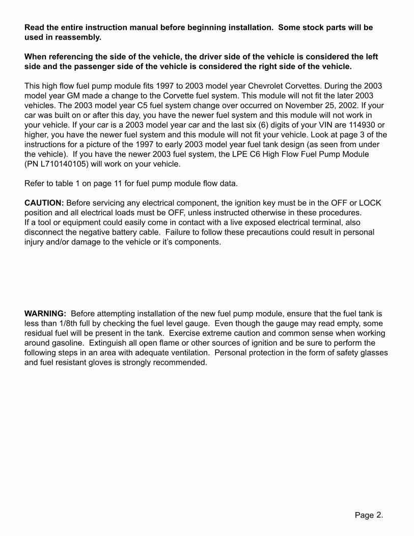
9. Detach the fuel level transmitter from it’s mount by pushing in on the two (2) tabs on the backside of it’s mount.
10. With the fuel transmitter loose, reach into the opening and pull out the loop of convoluted plastic fuel line, this will ease the removal of the fuel pump assembly.
11. Pull the pump and transmitter assembly up at a 45 degree angle towards the outside of the car. Note that there is a large fuel strainer attached to the end of the white plastic module. Even with the fuel tank empty, the strainer will still be saturated with gasoline. Use a shop towel or drain pan to catch the excess fuel.
12. Prepare a clean work space and lay the complete pump assembly on clean, dry shop towels to catch any residual fuel as you disas-semble it.

Page 6.
13. Disassemble the pump assembly by sepa-rating the can from it’s lid. Do this by gently prying up at the three retaining points.
14. When removing the lid from the can, it can be helpful to use three small screwdrivers as wedges to hold the edge of the can as you pull the lid free.
15. This is what the pump assembly with the lid removed should look like. Disconnect the black and red wires from the side of the lid and slide the lid up along the orange fuel line.
16. Remove the convoluted fuel line from the top portion of the assembly by first cutting it with a razor blade along the indicated white arrow, then pulling it off of the metal tube. Cut long ways along the white arrow indicated and remove the line.
Page 7.
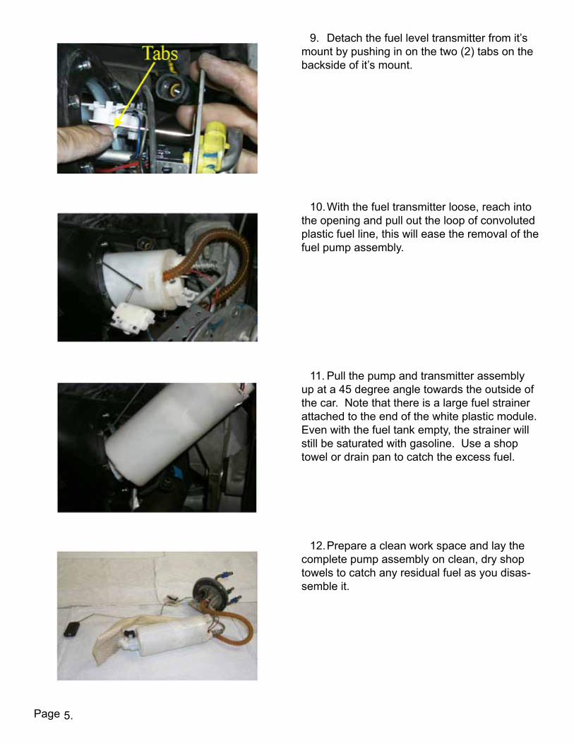
17. Insert the top cover over the new fuel line on the LPE provided fuel pump assembly.
18. Insert the wires into the cut out end of the top cover and make sure that they are clipped into place.
19. Slide the Oetiker clamp over the end of the convoluted fuel line as shown. Be careful not to bend the Oetiker clamp as it will fit very tightly over the end of the convoluted hose.
20. Work the hose on to the metal fuel line fitting as shown. The hose is a very tight fitting hose so work the hose around the fitting to set it into place.
Page 8.
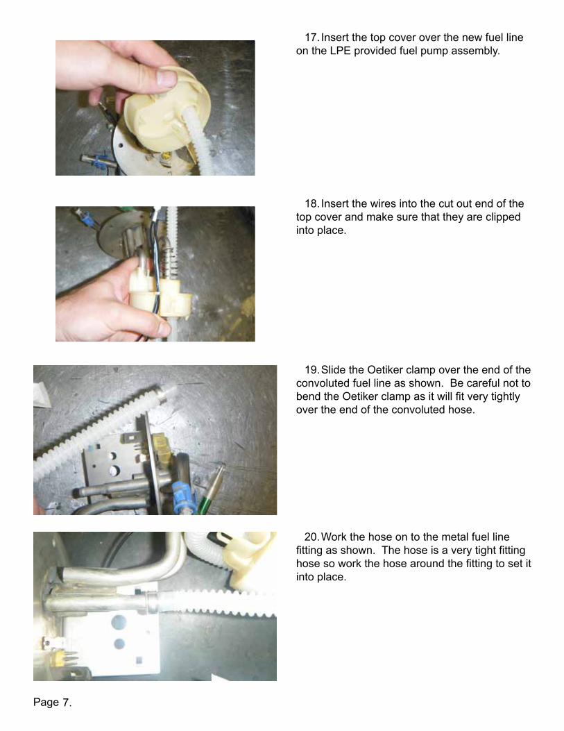
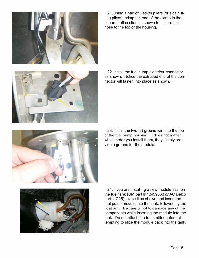
21. Using a pair of Oetiker pliers (or side cut-ting pliers), crimp the end of the clamp in the squared off section as shown to secure the hose to the top of the housing.
22. Install the fuel pump electrical connector as shown. Notice the extruded end of the con-nector will fasten into place as shown.
23. Install the two (2) ground wires to the top of the fuel pump housing. It does not matter which order you install them, they simply pro-vide a ground for the module.
24. If you are installing a new module seal on the fuel tank (GM part # 12459863 or AC Delco part # G25), place it as shown and insert the fuel pump module into the tank, followed by the float arm. Be careful not to damage any of the components while inserting the module into the tank. Do not attach the transmitter before at-tempting to slide the module back into the tank.

Page 9.
25. With the module and float arm inserted in the tank, attach the transmitter by snapping it into place on the metal bracket as shown.
26. Using a 10 mm or 7 mm socket (depend-ing on model year), install the six (6) new re-taining bolts (GM part # 11517825, they are also included with the module seal kit part # 12459863) and torque them to 62 in-lbs. Do not re-use the old retaining bolts, they are meant for one time use.
27. Install the three (3) fuel lines by lining up the release triggers with the slots on the con-nectors. Match the colored flags on the lines to the colored dots on the connectors of the fuel pump module. NOTE: Disregard the colors on the release trig-gers. Use the color markings underneath the triggers for the proper connection ports.
28. Reattach the electrical connector on the access cover (yellow connector indicated).
Page 10.
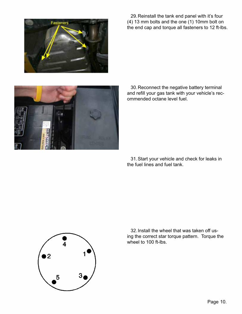
29. Reinstall the tank end panel with it’s four (4) 13 mm bolts and the one (1) 10mm bolt on the end cap and torque all fasteners to 12 ft-lbs.
30. Reconnect the negative battery terminal and refill your gas tank with your vehicle’s rec-ommended octane level fuel.
31. Start your vehicle and check for leaks in the fuel lines and fuel tank.
32. Install the wheel that was taken off us-ing the correct star torque pattern. Torque the wheel to 100 ft-lbs.

Page 11.
The fuel flow of this pump kit can be further enhanced with the use of a fuel pump voltage boosting device like the Kenne Bell Boost-A-Pump. The Boost-A-Pump is available through Lingenfelter Performance Engineering. The normal and boosted output of the pump is shown in the following table (Table 1).
Table 1Typical LPE High Flow C5 Corvette fuel pump module flow data
(at 58 psi/400 kPa fuel pressure)voltage fuel flow
Vdc gph lph12 49 186
13.5 63 23916 86 326
The TI/Walbro GSS series fuel pumps have been durability tested at elevated voltages for in excess of 500 hours of continuous operation.
With a fuel pump voltage boosting device, you only run the pump at the higher voltage when the additional fuel flow is needed. For naturally aspirated and nitrous applications, the elevated voltage mode can be triggered with a vacuum switch or with a TPS switch. On boosted applications (superchargers and turbochargers) the elevated voltage can be triggered with a pressure switch.
NOTICES:It is the responsibility of the purchaser to follow all guidelines and safety procedures supplied with this product and any other manufacture’s product used with this product. Lingenfelter Performance Engineering assumes no responsibility for damages resulting from accident, improper installation, misuse, abuse, improper operation, lack of reasonable care, or all previously stated reasons due to incompatibility with other manufacturer’s products.Lingenfelter Performance Engineering assumes no responsibility or liability for damages incurred from the use of products manufactured or sold by Lingenfelter Performance Engineering on vehicles used for competition racing.
It is the purchaser’s responsibility to check the state and local laws and sanctioning body requirements pertaining to the use of this product for racing applications. Lingenfelter Performance Engineering does not recommend nor condone the use of its products for illegal street racing.

Page 12.
This page is intentionally left blank.
Page
Lingenfelter Performance Engineering1557 Winchester Road
Decatur, IN 46733(260) 724-2552
(260) 724-0422 faxwww.lingenfelter.com
L710650197 C5 Corvette High Flow Fuel Pump Kit Instructions v3.0.indd
Many other items are available from LPE for your 1997-2003 Chevrolet Corvette including low temperature thermostats, camshafts, supercharger kits, CNC ported cylinder heads, engine packages, ported throttle bodies, and port matched intake manifolds.
For additional product installation information and technical support, contact LPE or your LPE products distributor. You can also find technical support and usage discussions regarding this product and many other LPE products in our Internet forums:
http://www.lingenfelter.com/forum_lingenfelter/index.php
Follow us on Facebook!
http://www.facebook.com/home.php#!/lpehp
13.