installation instructions -...
TRANSCRIPT

KGBNP5201VSP
Installation Instructions
Gas Conversion Kit Natural---to---Propane for
Variable Speed, Condensing and
Non---Condensing Gas Furnaces
CERTIFIED
NOTE: Read the entire instruction manual before starting theinstallation.
SAFETY CONSIDERATION
FIRE, EXPLOSION, ELECTRICAL SHOCK, ANDCARBON MONOXIDE POISONING HAZARD
Failure to follow this warning could result in personalinjury or death.
This conversion kit shall be installed by a qualified serviceagency in accordance with the manufacturer’s instructionsand all applicable codes and requirements of the authorityhaving jurisdiction. If the information in these instructionsis not followed exactly, a fire, explosion, or production ofcarbon monoxide could result causing property damage,personal injury, or loss of life. The qualified service agencyis responsible for the proper installation of this furnace withthis kit. The installation is not proper and complete until theoperation of the converted appliance is checked as specifiedin the manufacturer’s instructions supplied with the kit.
! WARNING
LE FEU, L’EXPLOSION, CHOC ELECTRIQUE,ET MONOXYDE DE CARBONEEMPOISONNER
Cette trousse de conversion doit être installée par un servied’entretien qualifié, selon les instructions du fabricant etselon toutes les exigences et tous les codes pertinents del’autorité compétente. Assurezvous de bien suivre lesinstructions dans cette notice pour réduire au minimum lerisque d’incendie, d’explosion ou la production demonoxyde de carbone pouvant causer des dommagesmatériels, de blessure ou la mort. Le service d’entretienqualifié est responsable de l’installation de cette trousse.L’installation n’est pas adéquate ni complète tant que le bonfonctionnement de l’appereil converti n’a pas été vérfiéselon les instructions du fabricant fornies avec la trousse.
! AVERTISSEMENT
Installing and servicing heating equipment can be hazardous dueto gas and electrical components. Only trained and qualifiedpersonnel should install, repair, or service heating equipment.
Untrained personnel can perform basic maintenance functionssuch as cleaning and replacing air filters. Trained service
personnel must perform all other operations. When working onheating equipment, observe precautions in the literature, on tags,and on labels attached to or shipped with the unit, and othersafety precautions that may apply.
Follow all safety codes. In the United States, follow all safetycodes including the current edition of the National Fuel Gas Code(NFGC) NFPA No. 54/ANSI Z223.1. In Canada, refer to thecurrent edition of the National Standard of Canada, Natural Gasand Propane Installation Codes (NSCNGPIC),CAN/CSA--B149.1 and .2. Wear safety glasses and work gloves.Have a fire extinguisher available during start--up, adjustmentsteps, and service calls.
Recognize safety information. This is the safety--alert symbol
. When you see this symbol on the furnace and in instructionsor manuals, be alert to the potential for personal injury.Understand the signal words DANGER, WARNING, CAUTIONand NOTE. The words DANGER, WARNING, and CAUTIONare used with the safety alert symbol. DANGER identifies themost serious hazards which will result in severe personal injury ordeath. WARNING signifies a hazard which could result inpersonal injury or death. CAUTION is used to identify unsafepractices which may result in minor personal injury or productand property damage. NOTE is used to highlight suggestionswhich will result in enhanced installation, reliability, or operation.
INTRODUCTION
FIRE, EXPLOSION, ELECTRICAL SHOCK ANDCARBON MONOXIDE POISONING HAZARD
Failure to follow instructions could result in personal injury,death or property damage.
Improper installation, adjustment, alteration, service,maintenance, or use can cause carbon monoxide poisoning,explosion, fire, electrical shock, or other conditions, whichcould result in personal injury or death. Consult yourdistributor or branch for information or assistance. Thequalified installer or agency must use onlyfactory--authorized kits or accessories when servicing thisproduct.
! WARNING
FIRE, EXPLOSION, ELECTRICAL SHOCKHAZARD
Failure to follow this warning could result in personalinjury, death or property damage.
Gas supply MUST be shut off before disconnectingelectrical power and proceeding with conversion.
! WARNING

2
ELECTRICAL SHOCK, FIRE OR EXPLOSIONHAZARD
Failure to follow this warning could result in personalinjury, death or property damage.
Before installing, modifying, or servicing system, mainelectrical disconnect switch must be in the OFF position andinstall a lockout tag. There may be more than onedisconnect switch. Lock out and tag switch with a suitablewarning label. Verify proper operation after servicing.
! WARNING
This instruction covers the installation of gas conversion kit PartNo. KGBNP5201VSP to convert the following furnaces fromnatural gas usage to propane gas usage. See appropriate sectionfor your furnace type.
Section 1—59MN7 & 987M 4-Way Multipoise, Hot SurfaceIgnition, Modulating Condensing Furnaces. This kit is designedfor use in furnaces with 60,000 through 120,000 Btuh gas inputrates.
Section 2—59TN6, 59TP6, 926T, 986T, & PG96V_T 4-WayMultipoise, Hot Surface Ignition, 2--Stage, Variable--SpeedCondensing Furnaces. 59TN6A applies to 60,000 to 120,000Btuh gas input rates. 986TA & PG96VAT applies to 40,000 to120,000 Btuh gas input rates.
Section 3—58CTW, 58CVA, 58CVX, 314AAV, 315AAV, ,315JAV, PG8MVA, & PG8JVA 33.3--In. (846 mm) High,Induced--Combustion, Hot-- Surface Ignition, 2-Stage,Variable-Speed, Non-Condensing Furnaces. This kit is designedfor use in furnaces with 42,000 through 154,000 Btuh gas inputrates.
DESCRIPTION AND USAGEThis kit is designed for use in the furnaces listed above. See Table1 for kit contents. To accommodate many different furnacemodels, more parts are shipped in kit than will be needed tocomplete conversion. When installation is complete, discard extraparts.
Table 1 – Kit ContentsQTY. PART NUMBER DESCRIPTION1 EF39ZW002 VALVE CVRSN KIT - W/R F92-1021002 EF39ZW023 VALVE CVRSN KIT - W/R SPRING 92-0659
1 HK02LB008 SWITCH, LOW GAS PRESSURE
1 323269-704 BAG ASSEMBLY Includes:7 LH32DB201 ORIFICE - #55
1 323272-702 BAG ASSEMBLY Includes:7 LH32DB206 ORIFICE - #56
1 323269-703 BAG ASSEMBLY Includes:
Kit Contents (Continued)7 LH32DB209 ORIFICE - 1.25mm
1 323751-702 BAG ASSEMBLY Includes:7 LH32DB210 ORIFICE - 1.30mm
1 337932-701 BAG ASSEMBLY Includes:7 FAJ5812B SCREW - SPOILER CONDNESING1 328456-402 BIT, DRILL 7/64”
1 337932-702 BAG ASSEMBLY Includes:7 327593-401 SCREW - SPOILER NON-CONDENSING1 328456-401 BIT, DRILL 5/64”
1 337932-703 BAG ASSEMBLY Includes:1 66175D55 CONNECTOR-1/4QC ME BOTH ENDS1 CA01JZ001 CONNECTOR - BRASS 1/8” NPT X2”1 CA15RA001 ELBOW, STREET - 150# 1/8” NPT1 CA16JQ001 ELBOW, STREET - BRASS 1/8” NPT1 CA21JQ001 TEE, STREET - MALE BRANCH (BRASS)1 CA21JZ001 TEE - MALE BRANCH (BRASS)1 CA52JZ103 NIPPLE - HEX (BRASS)1 HY89SC047 CONNECTOR,SPLC - 3/16”1 HY76TB125 WIRE TIE
1 W182X23--04--018 WIRE ASSY - ORANGE1 W182X66--04--012 WIRE ASSY - ORANGE1 W182X06--04--012 WIRE ASSY - ORANGE1 W182X66--04--018 WIRE ASSY - ORANGE
1 340070-701 LABEL SHEET Includes:1 340070-201 CONVERSION RATING PLATE1 340070-202 GAS CONTROL CONVERSION LABEL1 340070-203 GAS CONTROL ADJUSTMENT LABEL1 340070-204 CONVERSION RATING PLATE1 340070-205 CONVERSION RESPONSIBILITY LABEL
1 340070-702 LABEL SHEET Includes:1 340070-206 CONVERSION RATING PLATE1 340070-209 CONVERSION RATING PLATE
1 340070-703 LABEL SHEET Includes:1 340070-211 CONVERSION RATING PLATE1 340070-214 CONVERSION RATING PLATE
1 AG-KGBNP5201VSP-XX INSTALLATION INSTRUCTIONS
SECTION 1
Table 2 – Condensing FurnacesMODEL NUMBERS BEGINNING WITH:59MN7 987M
INSTALLATION1. Set room thermostat to lowest setting or “OFF”.
2. Remove outer doors.
3. Disconnect power at external disconnect, fuse or circuitbreaker.
4. Turn off gas at external shut-off or gas meter.
5. Remove outer doors and set aside.
6. Turn electric switch on gas valve to OFF. See Fig. 1.
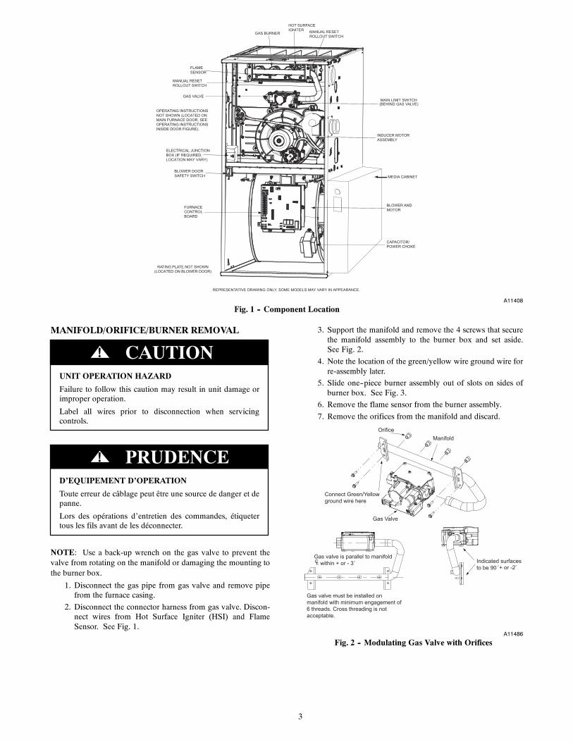
3
RATING PLATE NOT SHOWN(LOCATED ON BLOWER DOOR)
GAS VALVEMAIN LIMIT SWITCH(BEHIND GAS VALVE)
REPRESENTATIVE DRAWING ONLY, SOME MODELS MAY VARY IN APPEARANCE.
ELECTRICAL JUNCTIONBOX (IF REQUIRED, LOCATION MAY VARY)
MEDIA CABINET
OPERATING INSTRUCTIONSNOT SHOWN (LOCATED ONMAIN FURNACE DOOR, SEE OPERATING INSTRUCTIONS INSIDE DOOR FIGURE).
FURNACECONTROLBOARD
MANUAL RESETROLLOUT SWITCH
FLAMESENSOR
MANUAL RESETROLLOUT SWITCH
GAS BURNER
HOT SURFACEIGNITER
INDUCER MOTORASSEMBLY
BLOWER ANDMOTOR
CAPACITOR/POWER CHOKE
BLOWER DOORSAFETY SWITCH
A11408
Fig. 1 -- Component Location
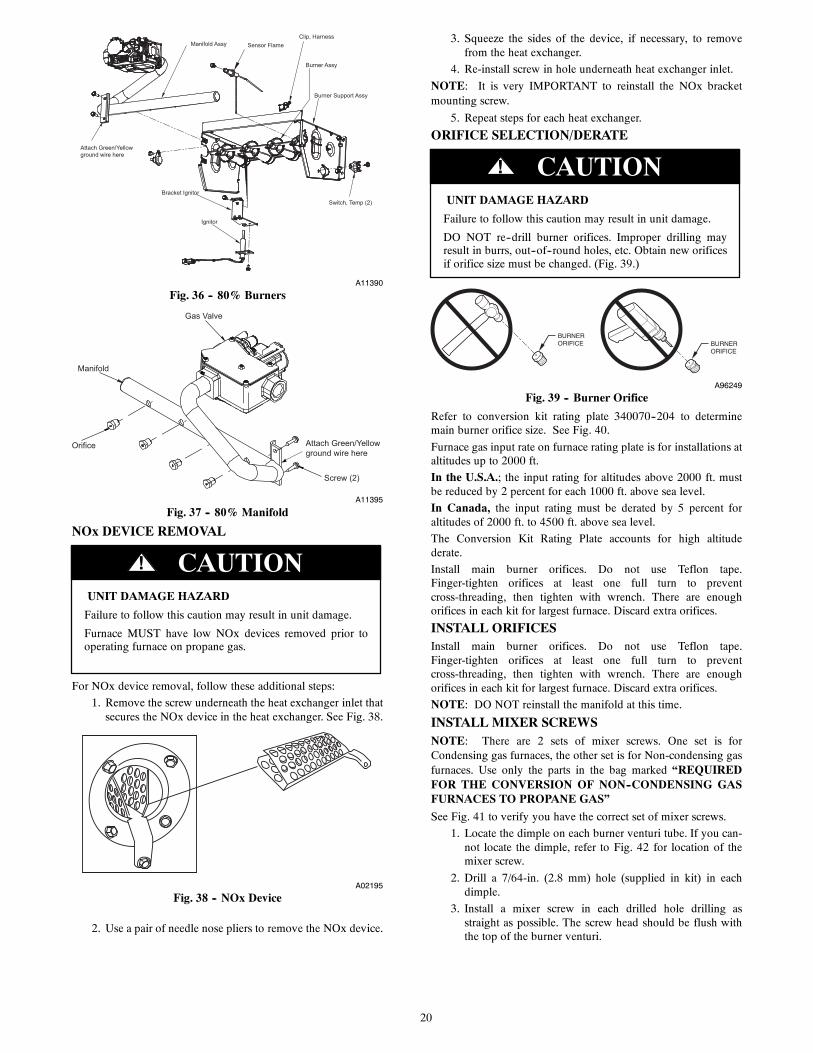
MANIFOLD/ORIFICE/BURNER REMOVAL
UNIT OPERATION HAZARD
Failure to follow this caution may result in unit damage orimproper operation.
Label all wires prior to disconnection when servicingcontrols.
CAUTION!
D’EQUIPEMENT D’OPERATION
Toute erreur de câblage peut être une source de danger et depanne.
Lors des opérations d’entretien des commandes, étiquetertous les fils avant de les déconnecter.
PRUDENCE!
NOTE: Use a back-up wrench on the gas valve to prevent thevalve from rotating on the manifold or damaging the mounting tothe burner box.
1. Disconnect the gas pipe from gas valve and remove pipefrom the furnace casing.
2. Disconnect the connector harness from gas valve. Discon-nect wires from Hot Surface Igniter (HSI) and FlameSensor. See Fig. 1.
3. Support the manifold and remove the 4 screws that securethe manifold assembly to the burner box and set aside.See Fig. 2.
4. Note the location of the green/yellow wire ground wire forre-assembly later.
5. Slide one--piece burner assembly out of slots on sides ofburner box. See Fig. 3.
6. Remove the flame sensor from the burner assembly.
7. Remove the orifices from the manifold and discard.
Orifice
Connect Green/Yellowground wire here
Manifold
Gas Valve
Gas valve must be installed onmanifold with minimum engagement of6 threads. Cross threading is notacceptable.
CLGas valve is parallel to manifold within + or - 3˚ Indicated surfaces
to be 90 ˚+ or -2˚
A11486
Fig. 2 -- Modulating Gas Valve with Orifices

4
FLAME SENSOR(BELOW BURNER)
FLAME ROLLOUTSWITCH
BRACKET, IGNITERIGNITERBURNER SUPT. ASSY
BURNER ASSY
A11403
Fig. 3 -- Burner Assembly
ORIFICE SELECTION/DERATE
UNIT DAMAGE HAZARD
Failure to follow this caution may result in unit damage.
DO NOT re--drill burner orifices. Improper drilling mayresult in burrs, out--of--round holes, etc. Obtain new orificesif orifice size must be changed. See Fig. 4.
CAUTION!
BURNER ORIFICE BURNER
ORIFICE
A96249
Fig. 4 -- Burner Orifice
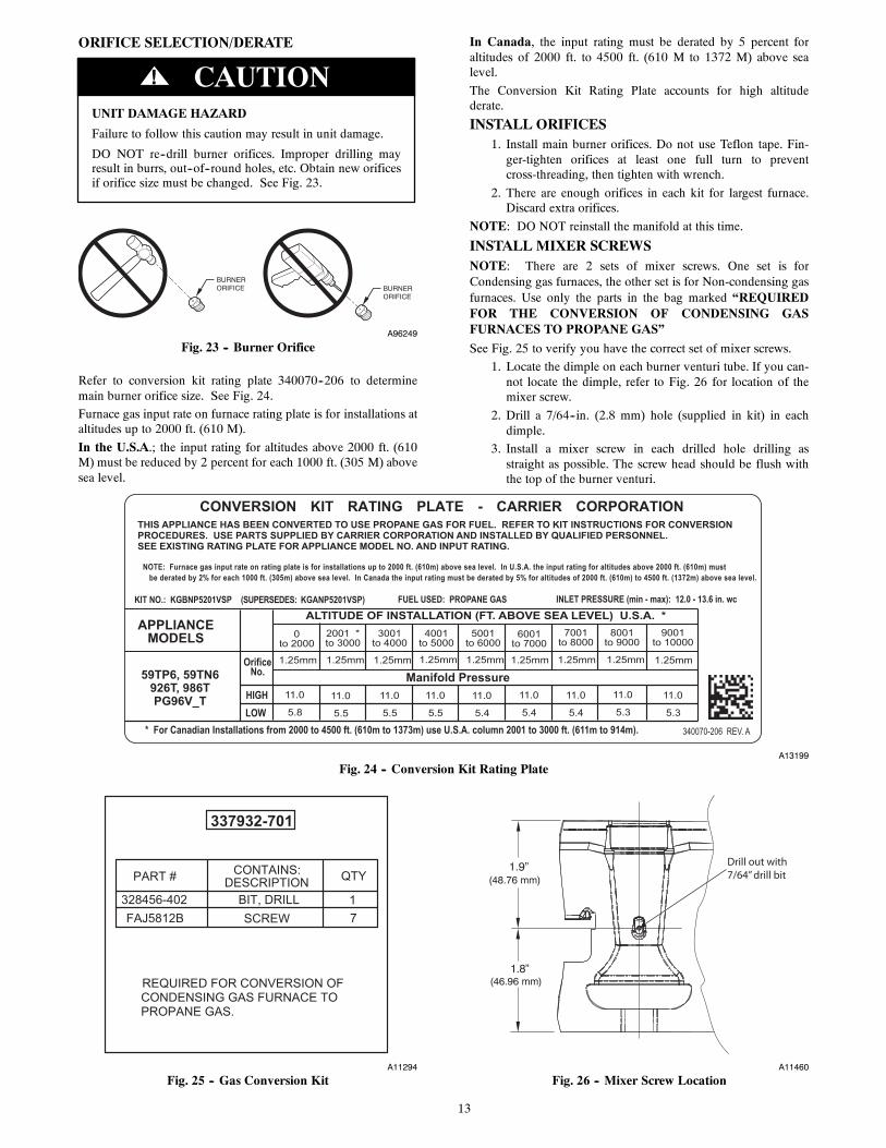
Refer to conversion kit rating plate 340070--201 to determinemain burner orifice size. See Fig. 18.
Furnace gas input rate on furnace rating plate is for installations ataltitudes up to 2000 ft.
In the U.S.A.; the input rating for altitudes above 2000 ft. must bereduced by 2 percent for each 1000 ft. above sea level.
In Canada, the input rating must be derated by 5 percent foraltitudes of 2000 ft. to 4500 ft. above sea level.
The Conversion Kit Rating Plate accounts for high altitudederate.
INSTALL ORIFICESInstall main burner orifices. Do not use Teflon tape.Finger--tighten orifices at least one full turn to preventcross--threading, then tighten with wrench. There are enoughorifices in each kit for largest furnace. Discard extra orifices.
NOTE: DO NOT reinstall the manifold at this time.
INSTALL MIXER SCREWSNOTE: There are 2 sets of mixer screws. One set is forCondensing gas furnaces, the other set is for Non-condensing gasfurnaces. Use only the parts in the bag marked “REQUIREDFOR THE CONVERSION OF CONDENSING GASFURNACES TO PROPANE GAS”
See Fig. 5 to verify you have the correct set of mixer screws.
1. Locate the dimple on each burner venturi tube. If you can-not locate the dimple, refer to Fig. 6 for location of themixer screw.
2. Drill a 7/64--in. (2.8 mm) hole (supplied in kit) in eachdimple.
3. Install a mixer screw in each drilled hole drilling asstraight as possible. The screw head should be flush withthe top of the burner venturi.
A11294
Fig. 5 -- Gas Conversion Kit
1.9”(48.76 mm)
1.8”(46.96 mm)
Drill out with7/64” drill bit
A11460
Fig. 6 -- Mixer Screw Location
REINSTALL BURNER ASSEMBLYTo reinstall burner assembly:
1. Attach flame sensor to burner assembly.
2. Insert one--piece burner in slot on sides of burner box andslide burner back in place.
3. Reattach HSI wires to HSI.
4. Verify igniter to burner alignment. See Fig. 7 and 8.
2-1/2-in.(64.4)
1-1/4-in.(31.8)
A11405
Fig. 7 -- Igniter Position -- Top View

5
2 − in.
(2.5 mm
3/8 − in.
3/16− in.
, +0.8 -1.5)
(50 mm)
(9.6 mm)
(4.6 mm)
3/32− in., +1/32 -3/64-in.
A12392
Fig. 8 -- Igniter Position -- Side View
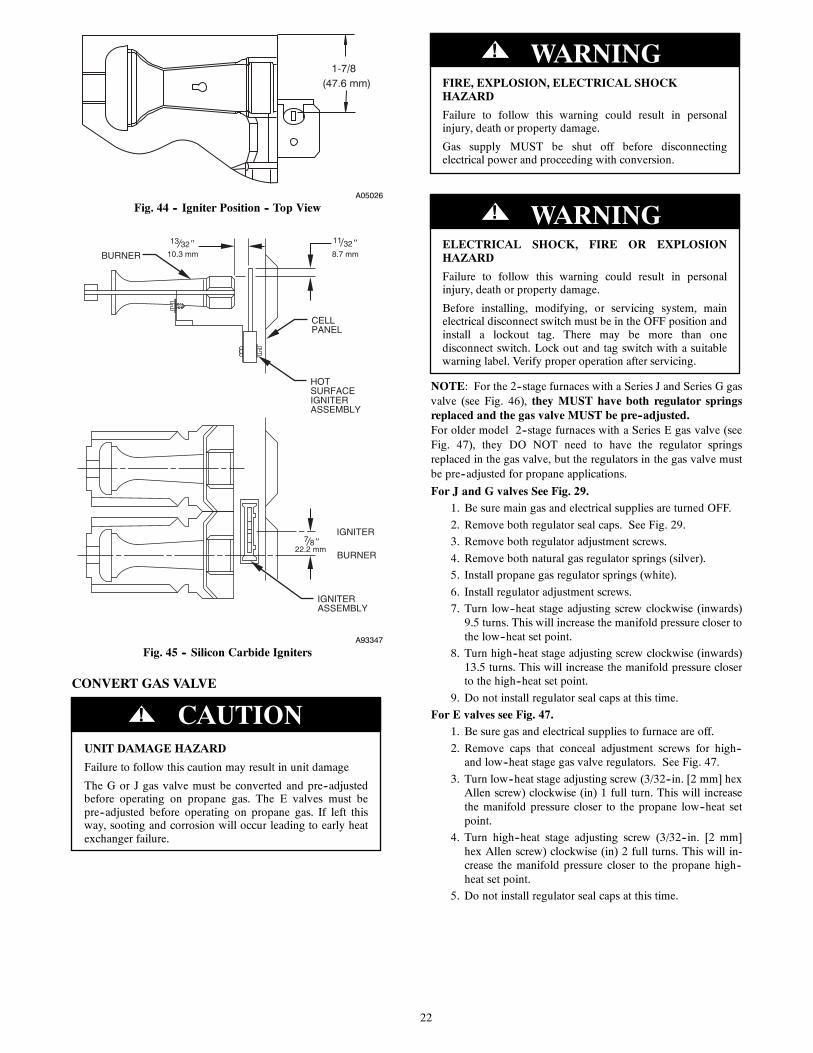
CONVERT GAS VALVE
FIRE, EXPLOSION, ELECTRICAL SHOCKHAZARD
Failure to follow this warning could result in personalinjury, death or property damage.
Gas supply MUST be shut off before disconnectingelectrical power and proceeding with conversion.
! WARNING
ELECTRICAL SHOCK, FIRE OR EXPLOSIONHAZARD
Failure to follow this warning could result in personalinjury, death or property damage.
Before installing, modifying, or servicing system, mainelectrical disconnect switch must be in the OFF position andinstall a lockout tag. There may be more than onedisconnect switch. Lock out and tag switch with a suitablewarning label. Verify proper operation after servicing.
! WARNING
Refer to Fig. 9 and 10.
A11373
Fig. 9 -- Propane Jumper
A11375
Fig. 10 -- Installing Propane Jumper
NOTE: The Propane jumper for the modulating gas valve isvery small. Needle-nose pliers are required to insert the jumperinto the valve. If the jumper is not installed, the valve will notoperate properly on propane.
1. Locate the round “NAT. GAS” sticker on the top of thegas valve.
2. Peel the sticker off and discard.
3. Note the small square opening in the top of the gas valve.
4. Note the 2 jumper pins inside the modulating gas valve.
5. Remove the small black plastic propane jumper from theenvelope.
6. Use needle-nosed pliers to hold the jumper by the tab onthe end.
7. Insert the jumper on the pins inside the gas valve.
8. Cover the opening in the gas valve with the label marked“LP GAS”
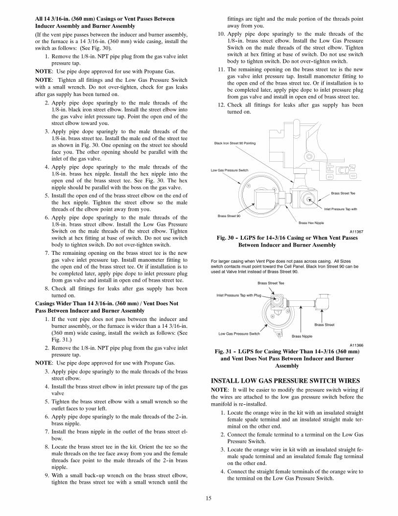
INSTALL LOW GAS PRESSURE SWITCHNOTE: Install the Low Gas Pressure Switch before installing themanifold on the burner assembly.
There are 2 ways to mount the Low Gas Pressure Switch.
All 14 3/16-in. (360 mm) Casings or Vent Passes BetweenInducer Assembly and Burner Assembly
If the vent pipe passes between the inducer and burner assembly,or the furnace is a 14 3/16-in. (360 mm) wide casing, install theswitch as follows. See Fig. 11.
Brass Street Tee
Brass Hex Nipple
Brass Street 90
Low Gas Pressure Switch
Black Iron Street 90 Pointing
Inlet Pressure Tap with
A11367
Fig. 11 -- LGPS for 14--3/16 (360 mm) Casing or When VentPasses Between Inducer and Burner Assembly

6
1. Remove the 1/8-in. NPT pipe plug from the gas valve inletpressure tap.
NOTE: Use pipe dope approved for use with Propane Gas.
NOTE: Tighten all fittings and the Low Gas Pressure Switchwith a small wrench. Do not over-tighten, check for gas leaksafter gas supply has been turned on.
FIRE AND EXPLOSION HAZARD
Failure to follow this warning could result in personal injuryand/or death.
NEVER test for gas leaks with an open flame. Use acommercially available soap solution made specifically forthe detection of leaks to check all connections. A fire orexplosion may result causing property damage, personalinjury or loss of life.
! WARNING
2. Apply pipe dope sparingly to the male threads of the1/8-in. black iron street elbow. Install the street elbow intothe gas valve inlet pressure tap. Point the open end of thestreet elbow toward you.
3. Apply pipe dope sparingly to the male threads of the1/8-in. brass street tee. Install the male end of the street teeas shown in Fig. 11. One opening on the street tee shouldface you. The other opening should be parallel with theinlet of the gas valve.
4. Apply pipe dope sparingly to the male threads of the1/8-in. brass hex nipple. Install the hex nipple into theopen end of the brass street tee. See Fig. 11. The hexnipple should be parallel with the boss on the gas valve.
5. Install the open end of the brass street elbow on the end ofthe hex nipple. Tighten the street elbow so the malethreads of the elbow point away from you.
6. Apply pipe dope sparingly to the male threads of the1/8-in. brass street elbow. Install the Low Gas PressureSwitch on the male threads of the street elbow. Tightenswitch at hex fitting at base of switch. Do not use switchbody to tighten switch. Do not over-tighten switch.
7. The remaining opening on the brass street tee is the newgas valve inlet pressure tap. Install manometer fitting tothe open end of the brass street tee. Or if installation is tobe completed later, apply pipe dope to inlet pressure plugfrom gas valve and install in open end of brass street tee.
8. Check all fittings for leaks after gas supply has beenturned on.
Casings Wider Than 14 3/16-in. (360 mm) / Vent Does NotPass Between Inducer and Burner Assembly
1. If the vent pipe does not pass between the inducer andburner assembly, or the furnace is wider than a 14 3/16-in.(360 mm) wide casing, install the switch as follows. SeeFig. 12.
2. Remove the 1/8-in. NPT pipe plug from the gas valve inletpressure tap.
NOTE: Use pipe dope approved for use with Propane Gas.
3. Apply pipe dope sparingly to the male threads of the brassstreet elbow.
4. Install the brass street elbow in inlet pressure tap of the gasvalve
5. Tighten the brass street elbow with a small wrench so theoutlet faces to your left.
6. Apply pipe dope sparingly to the male threads of the 2--in.brass nipple.
7. Install the brass nipple in the outlet of the brass street el-bow.
8. Locate the brass street tee in the kit. Orient the tee so themale threads on the tee face away from you and the femalethreads face point to the male threads of the 2--in brassnipple.
9. With a small back--up wrench on the brass street elbow,tighten the brass street tee with a small wrench until thefittings are tight and the male portion of the threads pointaway from you.
10. Apply pipe dope sparingly to the male threads of the1/8--in. brass street elbow. Install the Low Gas PressureSwitch on the male threads of the street elbow. Tightenswitch at hex fitting at base of switch. Do not use switchbody to tighten switch. Do not over--tighten switch.
11. The remaining opening on the brass street tee is the newgas valve inlet pressure tap. Install manometer fitting tothe open end of the brass street tee. Or if installation is tobe completed later, apply pipe dope to inlet pressure plugfrom gas valve and install in open end of brass street tee.
12. Check all fittings for leaks after gas supply has beenturned on.
Brass Street
Brass Nipple
For larger casing when Vent Pipe does not pass across casing. All Sizes switch contacts must point toward the Cell Panel. Black Iron Street 90 can be used at Valve Inlet instead of Brass Street 90.
Low Gas Pressure Switch
Inlet Pressure Tap with Plug
Brass Street Tee
A11366
Fig. 12 -- LGPS for Casing Wider Than 14--3/16 (360 mm)and Vent Does Not Pass Between Inducer and Burner As-
sembly
INSTALL LOW GAS PRESSURE SWITCH WIRESNOTE: It will be easier to modify the pressure switch wiring ifthe wires are attached to the low gas pressure switch before themanifold is re--installed.
1. Locate the orange wire in the kit with an insulated straightfemale spade terminal and an insulated straight male ter-minal on the other end.
2. Connect the female terminal to a terminal on the Low GasPressure Switch.
3. Locate the orange wire in kit with an insulated straight fe-male spade terminal and an insulated female flag terminalon the other end.
4. Connect the straight female terminals of the orange wire tothe terminal on the Low Gas Pressure Switch.
INSTALL MANIFOLD1. Align the orifices in the manifold assembly with the sup-
port rings on the end of the burner.
2. Insert the orifices in the support rings of the burners. Man-ifold mounting tabs should fit flush against the burner box
NOTE: If manifold does not fit flush against the burner box, theburners are not fully seated forward. Remove the manifold andcheck burner positioning in the burner box assembly.
3. Attach the green/yellow wire and ground terminal to oneof the manifold mounting screws.
4. Install the remaining manifold mounting screws.

7
5. Connect the wires to the flame sensor and hot surface ig-niter.
6. Connect the connector harness to gas valve
NOTE: Use only propane-resistant pipe dope. Do not use Teflontape.
7. Insert the gas pipe through the grommet in the casing. Ap-ply a thin layer of pipe dope to the threads of the pipe andthread the pipe into the gas valve.
NOTE: Use a back-up wrench on the gas valve to prevent thevalve from rotating on the manifold or damaging the mounting tothe burner box.
8. With a back-up wrench on the inlet boss of the gas valve,finish tightening the gas pipe to the gas valve.
9. Turn gas on at electric switch on gas valve.
MODIFY PRESSURE SWITCH WIRING
UNIT OPERATION HAZARD
Failure to follow this caution may result in unit damage orimproper operation.
Label all wires prior to disconnection when servicingcontrols.
CAUTION!
D’EQUIPEMENT D’OPERATION
Toute erreur de câblage peut être une source de danger et depanne.Lors des opérations d’entretien des commandes, étiquetertous les fils avant de les déconnecter.
PRUDENCE!
1. Disconnect the orange wire from Low Pressure SwitchLPS on inducer housing.
2. Connect the orange wire from the Low Pressure Switch tothe orange wire with the insulated male spade terminal.
3. Connect the orange wire with the female flag terminalfrom the Low Gas Pressure Switch to the terminal on theLow Pressure Switch.
4. Route orange wires along wire harness. If possible, securewith wire tie provided in kit.
CHECK INLET GAS PRESSURE
UNIT DAMAGE HAZARD
Failure to follow this caution may result in unit damage.
DO NOT operate furnace more than one minute to checkinlet gas pressure, as conversion is not complete at this time.
CAUTION!
NOTE: This kit is to be used only when inlet gas pressure isbetween 12.0--in. W.C. and 13.6--in. W.C.
1. Verify manometer is connected to inlet pressure tap on gasvalve.
2. Turn on furnace power supply.
3. Turn gas supply manual shutoff valve to ON position.
FIRE, EXPLOSION, ELECTRICAL SHOCKHAZARD
Failure to follow this warning could result in personalinjury, death or property damage.
Gas supply MUST be shut off before disconnectingelectrical power and proceeding with conversion.
! WARNING
ELECTRICAL SHOCK, FIRE OR EXPLOSIONHAZARD
Failure to follow this warning could result in personalinjury, death or property damage.
Before installing, modifying, or servicing system, mainelectrical disconnect switch must be in the OFF position andinstall a lockout tag. There may be more than onedisconnect switch. Lock out and tag switch with a suitablewarning label. Verify proper operation after servicing.
! WARNING
4. Turn furnace gas valve switch to ON position.
5. Turn Setup Switch SW1--2 on furnace control ON. SeeFig. 13.
6. Jumper R--W/W1 and R--W2 thermostat connections oncontrol.
Model Plug
Setup Switches SW1, 1 thru 8
SW2 A/C Air FlowSetup SwitchesAC 1 through AC 3
OA
T PL9
A B C D
PL4
HU
MPL7
W2 Y1 DHUM
SW4
SW2
SW3
CommunicationConnection
24 VACHUM Output(0.5 AMPMAX)
SW3 Continuous Fan(CF) airflow setupswitches CF 1 throughCF 3
Outside Air Thermistor
SW4
A11471
Fig. 13 -- Furnace Control
7. When main burners ignite, confirm inlet gas pressure isbetween 12.0--in. W.C. and 13.6--in. W.C.
8. Remove jumper across R--W/W1 and R--W2 thermostatconnections to terminate call for heat.
9. Turn furnace gas valve switch to OFF position.
10. Turn gas supply manual shutoff valve to OFF position.
11. Turn off furnace power supply.
12. Remove manometer.
8
13. Apply pipe dope sparingly to end of inlet gas pipe plugand install into unused end of 1/8 in. tee. Use a smallback--up wrench on tee when tightening gas inlet pipeplug. See Fig. 11 and 12.
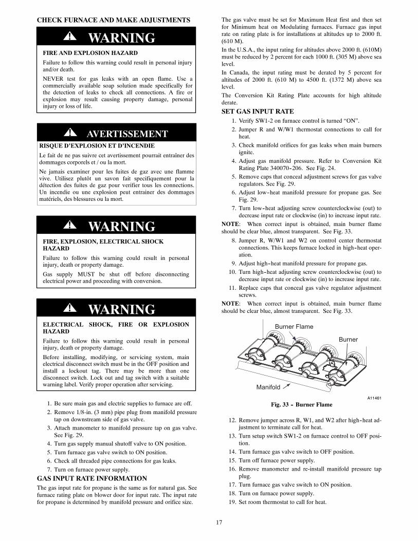
CHECK FURNACE AND MAKE ADJUSTMENTS
FIRE AND EXPLOSION HAZARD
Failure to follow this warning could result in personal injuryand/or death.
NEVER test for gas leaks with an open flame. Use acommercially available soap solution made specifically forthe detection of leaks to check all connections. A fire orexplosion may result causing property damage, personalinjury or loss of life.
! WARNING
RISQUE D’EXPLOSION ET D’INCENDIE
Le fait de ne pas suivre cet avertissement pourrait entraîner desdommages corporels et / ou la mort.
Ne jamais examiner pour les fuites de gaz avec une flammevive. Utilisez plutôt un savon fait specifiquement pour ladétection des fuites de gaz pour verifier tous les connections.Un incendie ou une explosion peut entrainer des dommagesmatériels, des blessures ou la mort.
! AVERTISSEMENT
1. Be sure main gas and electric supplies to furnace are off.
2. Remove 1/8-in. (3 mm) pipe plug from manifold pressuretap on downstream side of gas valve.
3. Attach manometer to manifold pressure tap on gas valve.See Fig. 14.
4. Turn gas supply manual shutoff valve to ON position.
5. Turn furnace gas valve switch to ON position.
6. Check all threaded pipe connections for gas leaks.
7. Turn on furnace power supply.
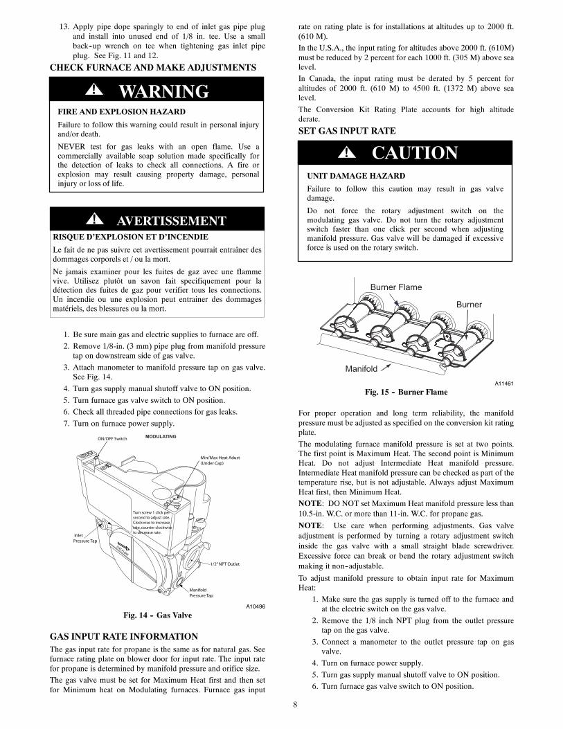
ON/OFF Switch
1/2” NPT Outlet
ManifoldPressure Tap
InletPressure Tap
Min/Max Heat Adust(Under Cap)
GAS FLOW
MODULATING
Turn screw 1 click persecond to adjust rate. Clockwise to increaserate, counter clockwiseto decrease rate.
A10496
Fig. 14 -- Gas Valve
GAS INPUT RATE INFORMATIONThe gas input rate for propane is the same as for natural gas. Seefurnace rating plate on blower door for input rate. The input ratefor propane is determined by manifold pressure and orifice size.
The gas valve must be set for Maximum Heat first and then setfor Minimum heat on Modulating furnaces. Furnace gas input
rate on rating plate is for installations at altitudes up to 2000 ft.(610 M).
In the U.S.A., the input rating for altitudes above 2000 ft. (610M)must be reduced by 2 percent for each 1000 ft. (305 M) above sealevel.
In Canada, the input rating must be derated by 5 percent foraltitudes of 2000 ft. (610 M) to 4500 ft. (1372 M) above sealevel.
The Conversion Kit Rating Plate accounts for high altitudederate.
SET GAS INPUT RATE
UNIT DAMAGE HAZARD
Failure to follow this caution may result in gas valvedamage.
Do not force the rotary adjustment switch on themodulating gas valve. Do not turn the rotary adjustmentswitch faster than one click per second when adjustingmanifold pressure. Gas valve will be damaged if excessiveforce is used on the rotary switch.
CAUTION!
Burner Flame
Burner
ManifoldA11461
Fig. 15 -- Burner Flame
For proper operation and long term reliability, the manifoldpressure must be adjusted as specified on the conversion kit ratingplate.
The modulating furnace manifold pressure is set at two points.The first point is Maximum Heat. The second point is MinimumHeat. Do not adjust Intermediate Heat manifold pressure.Intermediate Heat manifold pressure can be checked as part of thetemperature rise, but is not adjustable. Always adjust MaximumHeat first, then Minimum Heat.
NOTE: DO NOT set Maximum Heat manifold pressure less than10.5-in. W.C. or more than 11-in. W.C. for propane gas.
NOTE: Use care when performing adjustments. Gas valveadjustment is performed by turning a rotary adjustment switchinside the gas valve with a small straight blade screwdriver.Excessive force can break or bend the rotary adjustment switchmaking it non--adjustable.
To adjust manifold pressure to obtain input rate for MaximumHeat:
1. Make sure the gas supply is turned off to the furnace andat the electric switch on the gas valve.
2. Remove the 1/8 inch NPT plug from the outlet pressuretap on the gas valve.
3. Connect a manometer to the outlet pressure tap on gasvalve.
4. Turn on furnace power supply.
5. Turn gas supply manual shutoff valve to ON position.
6. Turn furnace gas valve switch to ON position.

9
7. Turn Setup switch SW 1-2 to ON.
8. Verify Set-up switch SW 4-2 is turned OFF.
9. Jumper the R to W/W1 and W2 thermostat connections atthe furnace control board.
10. After the main burners ignite and the blower starts, con-firm Maximum Heat manifold pressure is correct, basedon the manifold pressure table on the Conversion Kit Rat-ing Plate.
11. To adjust the Maximum Heat manifold pressure, Slowlyturn the rotary adjustment switch counterclockwise to de-crease manifold pressure or clockwise to increase manifoldpressure. See Fig. 16.
12. Turn rotary adjustment switch no more than one click persecond until you obtain the required manifold pressure.
A11451
Fig. 16 -- Modulating Gas Valve Adjustment
Main burner flame should be clear blue, almost transparent. SeeFig. 15.
To adjust manifold pressure to obtain input rate for MinimumHeat:
1. Remove the jumper from W2 at the thermostat connec-tions at the furnace control board control.
2. Wait until the burners and the blower transitions to Minim-um Heat.
3. Verify the Minimum Heat manifold pressure is correct,based on the manifold pressure table on Conversion KitRating Plate.
4. To adjust the Minimum Heat manifold pressure, Slowlyturn the rotary adjustment switch counterclockwise to de-crease manifold pressure or clockwise to increase manifoldpressure. See Fig. 16.
5. Turn rotary adjustment switch no more than one click persecond until you obtain the required manifold pressure.This adjustment will not affect the previous MaximumHeat adjustment.
After adjusting the manifold pressure, allow the furnace tooperate an additional 5 minutes before checking Minimum HeatTemperature rise.
Furnace must operate within ranges of temperature rise specifiedon the furnace rating plate. Determine air temperature rise asfollows:
1. Place thermometers in return and supply ducts as near fur-nace as possible. Be sure thermometers do not see heat ex-changer so that radiant heat does not affect readings. Thispractice is particularly important with straight-run ducts.
2. When thermometer readings stabilize, subtract return-airtemperature from supply-air temperature to determine airtemperature rise.
3. Allow the furnace to run for at least 10 minutes beforechecking Temperature Rise.
If the temperature rise is too high or too low in Minimum Heat:
1. Remove jumpers from R and W/W1.
2. Wait until the blower off delay is completed.
3. Turn 115 VAC power off.
4. Check the position of Heat Rise Adjustment SwitchSW1-3. When set to ON, airflow is raised 18% higher forMinimum Heat and Intermediate Heat. Factory default po-sition is OFF.
5. Turn 115 VAC power on.
6. Jumper R to W/W1 and W2.
7. After burners ignite and blower starts allow the furnace torun for at least 10 minutes before checking TemperatureRise.
Maximum Heat Temperature Rise
If the temperature rise is too high or too low in Maximum Heat:
1. Remove jumpers from R, W1 and W2.
2. Wait until the blower off delay is completed.
3. Turn 115 VAC power off.
4. Check the position of the Efficiency/Comfort Adjustmentswitch SW1-4. When set to OFF (Efficiency Mode), air-flow is 10% higher for Minimum, 7.5% for IntermediateHeat, and 17.5% for Maximum Heat. Factory default posi-tion is ON (Comfort Mode).
5. Turn 115 VAC power on.
6. Re-check Minimum Heat Temperature Rise.
7. Remove jumpers across thermostat connections to termin-ate the call for heat. Wait until the blower off delay is com-pleted.
8. Turn gas supply manual shutoff valve to OFF position.
9. Turn off furnace power supply.
10. Remove manometer from the outlet pressure tap of the gasvalve.
11. Apply pipe dope sparingly to 1/8--in. NPT plug and re-in-stall outlet pressure tap on the gas valve.
12. Re-install plastic cap over rotary adjustment switch on thetop of the gas valve.
CHECK LOW GAS PRESSURE SWITCHThe newly installed low gas pressure switch is a safety deviceused to guard against adverse burner operating characteristics thatcan result from low gas supply pressure. Switch opens at not lessthan 7.2 in. W.C. and closes at not greater than 10.2 in. W.C.
This switch also prevents operation when the propane tank levelis low which can result in gas with a high concentration ofimpurities, additives, and residues that have settled to the bottomof the tank. Operation under these conditions can cause harm tothe heat exchanger system. This normally open switch closeswhen gas is supplied to gas valve under normal operatingpressure. The closed switch completes control circuit. Should aninterruption or reduction in gas supply occur, the gas pressure atswitch drops below low gas pressure switch setting, and switchopens. Any interruption in control circuit (in which low gaspressure switch is wired) quickly closes gas valve and stops gasflow to burners. When normal gas pressure is restored, the systemmust be electrically reset to re-establish normal heating operation.
Before leaving installation, observe unit operation through twocomplete heating cycles. During this time, turn gas supply to gasvalve off just long enough to completely extinguish burner flame,then instantly restore full gas supply. To ensure proper low gaspressure switch operation, observe that there is no gas supply toburners until after hot surface igniter begins glowing.
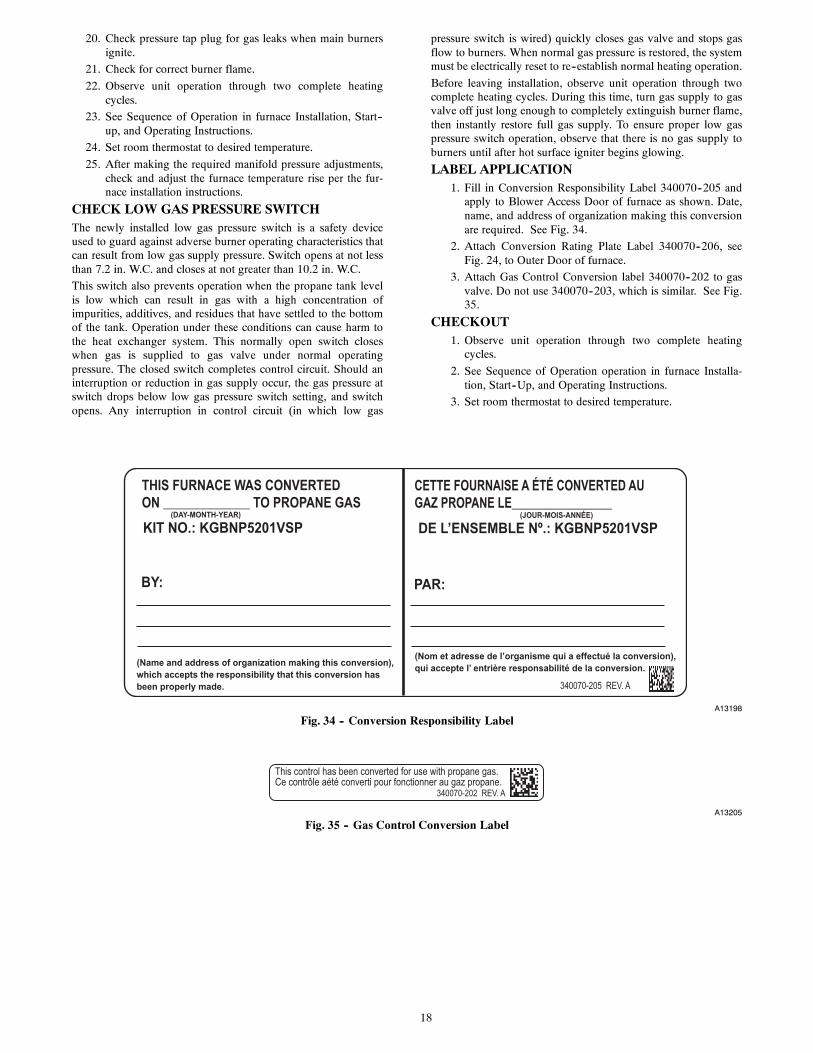
LABEL APPLICATION1. Fill in Conversion Responsibility Label 340070--205 and
apply to Blower Access Door of furnace as shown. See

10
Fig. 17. Date, name, and address of organization makingthis conversion are required.
2. Attach Conversion Rating Plate Label 340070--201 to out-er door of furnace. See Fig. 18.
3. Attach Gas Control Conversion Label 340070--202 to gasvalve. Do not use 340070--203, which is similar. See Fig.19.
A13198
Fig. 17 -- Conversion Responsibility Label
A13197
Fig. 18 -- Conversion Kit Rating Plate
A13205
Fig. 19 -- Gas Control Conversion Label
11
SECTION 2
Table 3 – Variable Speed Condensing FurnacesMODEL NUMBERS BEGINNING WITH:59TN6 986T59TP6 926TPG96V_T
INSTALLATION
FIRE, EXPLOSION, ELECTRICAL SHOCK ANDCARBON MONOXIDE POISONING HAZARD
Failure to follow instructions could result in personal injury,death or property damage.
Improper installation, adjustment, alteration, service,maintenance, or use can cause carbon monoxide poisoning,explosion, fire, electrical shock, or other conditions, whichcould result in personal injury or death. Consult yourdistributor or branch for information or assistance. Thequalified installer or agency must use onlyfactory--authorized kits or accessories when servicing thisproduct.
! WARNING
FIRE, EXPLOSION, ELECTRICAL SHOCK, ANDCARBON MONOXIDE POISONING HAZARD
Failure to follow this warning could result in personalinjury or death.
This conversion kit shall be installed by a qualified serviceagency in accordance with the manufacturer’s instructionsand all applicable codes and requirements of the authorityhaving jurisdiction. If the information in these instructionsis not followed exactly, a fire, explosion, or production ofcarbon monoxide could result causing property damage,personal injury, or loss of life. The qualified service agencyis responsible for the proper installation of this furnace withthis kit. The installation is not proper and complete until theoperation of the converted appliance is checked as specifiedin the manufacturer’s instructions supplied with the kit.
! WARNING
LE FEU, L’EXPLOSION, CHOC ELECTRIQUE,ET MONOXYDE DE CARBONEEMPOISONNER
Cette trousse de conversion doit être installée par un servied’entretien qualifié, selon les instructions du fabricant etselon toutes les exigences et tous les codes pertinents del’autorité compétente. Assurezvous de bien suivre lesinstructions dans cette notice pour réduire au minimum lerisque d’incendie, d’explosion ou la production demonoxyde de carbone pouvant causer des dommagesmatériels, de blessure ou la mort. Le service d’entretienqualifié est responsable de l’installation de cette trousse.L’installation n’est pas adéquate ni complète tant que le bonfonctionnement de l’appereil converti n’a pas été vérfiéselon les instructions du fabricant fornies avec la trousse.
! AVERTISSEMENT
FIRE, EXPLOSION, ELECTRICAL SHOCKHAZARD
Failure to follow this warning could result in personalinjury, death or property damage.
Gas supply MUST be shut off before disconnectingelectrical power and proceeding with conversion.
! WARNING
ELECTRICAL SHOCK, FIRE OR EXPLOSIONHAZARD
Failure to follow this warning could result in personalinjury, death or property damage.
Before installing, modifying, or servicing system, mainelectrical disconnect switch must be in the OFF position andinstall a lockout tag. There may be more than onedisconnect switch. Lock out and tag switch with a suitablewarning label. Verify proper operation after servicing.
! WARNING
1. Set room thermostat to lowest setting or “OFF”.
2. Remove outer doors.
3. Disconnect power at external disconnect, fuse or circuitbreaker.
4. Turn off gas at external shut-off or gas meter.
5. Remove outer doors and set aside.
6. Turn electric switch on gas valve to OFF. See Fig. 20.
12
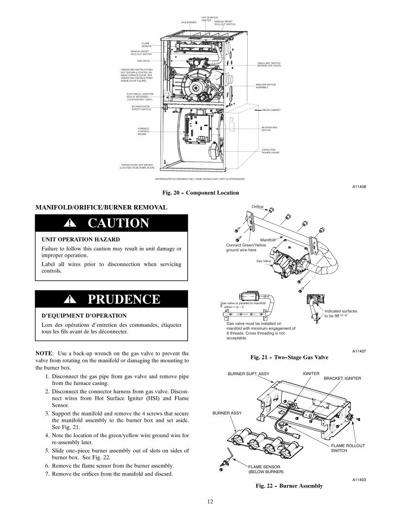
RATING PLATE NOT SHOWN(LOCATED ON BLOWER DOOR)
GAS VALVEMAIN LIMIT SWITCH(BEHIND GAS VALVE)
REPRESENTATIVE DRAWING ONLY, SOME MODELS MAY VARY IN APPEARANCE.
ELECTRICAL JUNCTIONBOX (IF REQUIRED, LOCATION MAY VARY)
MEDIA CABINET
OPERATING INSTRUCTIONSNOT SHOWN (LOCATED ONMAIN FURNACE DOOR, SEE OPERATING INSTRUCTIONS INSIDE DOOR FIGURE).
FURNACECONTROLBOARD
MANUAL RESETROLLOUT SWITCH
FLAMESENSOR
MANUAL RESETROLLOUT SWITCH
GAS BURNER
HOT SURFACEIGNITER
INDUCER MOTORASSEMBLY
BLOWER ANDMOTOR
CAPACITOR/POWER CHOKE
BLOWER DOORSAFETY SWITCH
A11408
Fig. 20 -- Component Location
MANIFOLD/ORIFICE/BURNER REMOVAL
UNIT OPERATION HAZARD
Failure to follow this caution may result in unit damage orimproper operation.
Label all wires prior to disconnection when servicingcontrols.
CAUTION!
D’EQUIPMENT D’OPERATION
Lors des opérations d’entretien des commandes, étiquetertous les fils avant de les déconnecter.
PRUDENCE!
NOTE: Use a back-up wrench on the gas valve to prevent thevalve from rotating on the manifold or damaging the mounting tothe burner box.
1. Disconnect the gas pipe from gas valve and remove pipefrom the furnace casing.
2. Disconnect the connector harness from gas valve. Discon-nect wires from Hot Surface Igniter (HSI) and FlameSensor.
3. Support the manifold and remove the 4 screws that securethe manifold assembly to the burner box and set aside.See Fig. 21.
4. Note the location of the green/yellow wire ground wire forre-assembly later.
5. Slide one--piece burner assembly out of slots on sides ofburner box. See Fig. 22.
6. Remove the flame sensor from the burner assembly.
7. Remove the orifices from the manifold and discard.
Orifice
Connect Green/Yellowground wire here
Manifold
Gas Valve
Gas valve must be installed onmanifold with minimum engagement of6 threads. Cross threading is notacceptable.
Indicated surfacesto be 90̊+ or -2˚
CLGas valve is parallel to manifold within + or - 3˚
A11407
Fig. 21 -- Two--Stage Gas Valve
FLAME SENSOR(BELOW BURNER)
FLAME ROLLOUTSWITCH
BRACKET, IGNITERIGNITERBURNER SUPT. ASSY
BURNER ASSY
A11403
Fig. 22 -- Burner Assembly
13
ORIFICE SELECTION/DERATE
UNIT DAMAGE HAZARD
Failure to follow this caution may result in unit damage.
DO NOT re--drill burner orifices. Improper drilling mayresult in burrs, out--of--round holes, etc. Obtain new orificesif orifice size must be changed. See Fig. 23.
CAUTION!
BURNER ORIFICE BURNER
ORIFICE
A96249
Fig. 23 -- Burner Orifice
Refer to conversion kit rating plate 340070--206 to determinemain burner orifice size. See Fig. 24.
Furnace gas input rate on furnace rating plate is for installations ataltitudes up to 2000 ft. (610 M).
In the U.S.A.; the input rating for altitudes above 2000 ft. (610M) must be reduced by 2 percent for each 1000 ft. (305 M) abovesea level.
In Canada, the input rating must be derated by 5 percent foraltitudes of 2000 ft. to 4500 ft. (610 M to 1372 M) above sealevel.
The Conversion Kit Rating Plate accounts for high altitudederate.
INSTALL ORIFICES1. Install main burner orifices. Do not use Teflon tape. Fin-
ger-tighten orifices at least one full turn to preventcross-threading, then tighten with wrench.
2. There are enough orifices in each kit for largest furnace.Discard extra orifices.
NOTE: DO NOT reinstall the manifold at this time.
INSTALL MIXER SCREWSNOTE: There are 2 sets of mixer screws. One set is forCondensing gas furnaces, the other set is for Non-condensing gasfurnaces. Use only the parts in the bag marked “REQUIREDFOR THE CONVERSION OF CONDENSING GASFURNACES TO PROPANE GAS”
See Fig. 25 to verify you have the correct set of mixer screws.
1. Locate the dimple on each burner venturi tube. If you can-not locate the dimple, refer to Fig. 26 for location of themixer screw.
2. Drill a 7/64--in. (2.8 mm) hole (supplied in kit) in eachdimple.
3. Install a mixer screw in each drilled hole drilling asstraight as possible. The screw head should be flush withthe top of the burner venturi.
A13199
Fig. 24 -- Conversion Kit Rating Plate
A11294
Fig. 25 -- Gas Conversion Kit
1.9”(48.76 mm)
1.8”(46.96 mm)
Drill out with7/64” drill bit
A11460
Fig. 26 -- Mixer Screw Location
14
REINSTALL BURNER ASSEMBLYTo reinstall burner assembly:
1. Attach flame sensor to burner assembly.
2. Insert one--piece burner in slot on sides of burner box andslide burner back in place.
3. Reattach HSI wires to HSI.
4. Verify igniter to burner alignment. See Fig. 27 and 28.
2-1/2-in.(64.4)
1-1/4-in.(31.8)
A11405
Fig. 27 -- Igniter Position -- Top View
2 − in.
(2.5 mm
3/8 − in.
3/16− in.
, +0.8 -1.5)
(50 mm)
(9.6 mm)
(4.6 mm)
3/32− in., +1/32 -3/64-in.
A12392
Fig. 28 -- Igniter Position -- Side View
CONVERT GAS VALVE
UNIT DAMAGE HAZARD
Failure to follow this caution may result in unit damage
The G or J gas valve must be converted and pre--adjustedbefore operating on propane gas. The E valves must bepre--adjusted before operating on propane gas. If left thisway, sooting and corrosion will occur leading to early heatexchanger failure.
CAUTION!
FIRE, EXPLOSION, ELECTRICAL SHOCKHAZARD
Failure to follow this warning could result in personalinjury, death or property damage.
Gas supply MUST be shut off before disconnectingelectrical power and proceeding with conversion.
! WARNING
ELECTRICAL SHOCK, FIRE OR EXPLOSIONHAZARD
Failure to follow this warning could result in personalinjury, death or property damage.
Before installing, modifying, or servicing system, mainelectrical disconnect switch must be in the OFF position andinstall a lockout tag. There may be more than onedisconnect switch. Lock out and tag switch with a suitablewarning label. Verify proper operation after servicing.
! WARNING
1. Refer to Fig. 29.
2. Be sure gas and electrical supplies to furnace are off.
3. Remove caps that conceal adjustment screws for high--heatand low--heat stage gas valve regulators. See Fig. 29.
4. Remove the high--heat and low--heat regulator adjustmentscrews.
5. Remove the high--heat and low--heat gas regulator springs(silver).
6. Install the high--heat and low--heat propane gas regulatorsprings (white).
7. Install the high--heat and low--heat regulator adjustmentscrews.
8. Turn high--heat stage adjusting screw clockwise (in) 13.5full turns. This will increase the manifold pressure closerto the propane high--heat set point. See Fig. 29.
9. Turn low--heat stage adjusting screw clockwise (in) 9.5full turns. This will increase the manifold pressure closerto the propane low--heat set point. See Fig. 29.
10. Do not install regulator seal caps at this time.
A05196
Fig. 29 -- Two--Stage Gas Valve
INSTALL LOW GAS PRESSURE SWITCHNOTE: Install the Low Gas Pressure Switch before installing themanifold on the burner assembly.
There are two ways to mount the Low Gas Pressure Switch.
15
All 14 3/16-in. (360 mm) Casings or Vent Passes BetweenInducer Assembly and Burner Assembly
(If the vent pipe passes between the inducer and burner assembly,or the furnace is a 14 3/16-in. (360 mm) wide casing, install theswitch as follows: (See Fig. 30).
1. Remove the 1/8-in. NPT pipe plug from the gas valve inletpressure tap.
NOTE: Use pipe dope approved for use with Propane Gas.
NOTE: Tighten all fittings and the Low Gas Pressure Switchwith a small wrench. Do not over-tighten, check for gas leaksafter gas supply has been turned on.
2. Apply pipe dope sparingly to the male threads of the1/8-in. black iron street elbow. Install the street elbow intothe gas valve inlet pressure tap. Point the open end of thestreet elbow toward you.
3. Apply pipe dope sparingly to the male threads of the1/8-in. brass street tee. Install the male end of the street teeas shown in Fig. 30. One opening on the street tee shouldface you. The other opening should be parallel with theinlet of the gas valve.
4. Apply pipe dope sparingly to the male threads of the1/8-in. brass hex nipple. Install the hex nipple into theopen end of the brass street tee. See Fig. 30. The hexnipple should be parallel with the boss on the gas valve.
5. Install the open end of the brass street elbow on the end ofthe hex nipple. Tighten the street elbow so the malethreads of the elbow point away from you.
6. Apply pipe dope sparingly to the male threads of the1/8-in. brass street elbow. Install the Low Gas PressureSwitch on the male threads of the street elbow. Tightenswitch at hex fitting at base of switch. Do not use switchbody to tighten switch. Do not over-tighten switch.
7. The remaining opening on the brass street tee is the newgas valve inlet pressure tap. Install manometer fitting tothe open end of the brass street tee. Or if installation is tobe completed later, apply pipe dope to inlet pressure plugfrom gas valve and install in open end of brass street tee.
8. Check all fittings for leaks after gas supply has beenturned on.
Casings Wider Than 14 3/16-in. (360 mm) / Vent Does NotPass Between Inducer and Burner Assembly
1. If the vent pipe does not pass between the inducer andburner assembly, or the furnace is wider than a 14 3/16-in.(360 mm) wide casing, install the switch as follows: (SeeFig. 31.)
2. Remove the 1/8-in. NPT pipe plug from the gas valve inletpressure tap.
NOTE: Use pipe dope approved for use with Propane Gas.
3. Apply pipe dope sparingly to the male threads of the brassstreet elbow.
4. Install the brass street elbow in inlet pressure tap of the gasvalve
5. Tighten the brass street elbow with a small wrench so theoutlet faces to your left.
6. Apply pipe dope sparingly to the male threads of the 2--in.brass nipple.
7. Install the brass nipple in the outlet of the brass street el-bow.
8. Locate the brass street tee in the kit. Orient the tee so themale threads on the tee face away from you and the femalethreads face point to the male threads of the 2--in brassnipple.
9. With a small back--up wrench on the brass street elbow,tighten the brass street tee with a small wrench until the
fittings are tight and the male portion of the threads pointaway from you.
10. Apply pipe dope sparingly to the male threads of the1/8--in. brass street elbow. Install the Low Gas PressureSwitch on the male threads of the street elbow. Tightenswitch at hex fitting at base of switch. Do not use switchbody to tighten switch. Do not over--tighten switch.
11. The remaining opening on the brass street tee is the newgas valve inlet pressure tap. Install manometer fitting tothe open end of the brass street tee. Or if installation is tobe completed later, apply pipe dope to inlet pressure plugfrom gas valve and install in open end of brass street tee.
12. Check all fittings for leaks after gas supply has beenturned on.
Brass Street Tee
Brass Hex Nipple
Brass Street 90
Low Gas Pressure Switch
Black Iron Street 90 Pointing
Inlet Pressure Tap with
A11367
Fig. 30 -- LGPS for 14--3/16 Casing or When Vent PassesBetween Inducer and Burner Assembly
Brass Street
Brass Nipple
For larger casing when Vent Pipe does not pass across casing. All Sizes switch contacts must point toward the Cell Panel. Black Iron Street 90 can be used at Valve Inlet instead of Brass Street 90.
Low Gas Pressure Switch
Inlet Pressure Tap with Plug
Brass Street Tee
A11366
Fig. 31 -- LGPS for Casing Wider Than 14--3/16 (360 mm)and Vent Does Not Pass Between Inducer and Burner
Assembly
INSTALL LOW GAS PRESSURE SWITCH WIRESNOTE: It will be easier to modify the pressure switch wiring ifthe wires are attached to the low gas pressure switch before themanifold is re--installed.
1. Locate the orange wire in the kit with an insulated straightfemale spade terminal and an insulated straight male ter-minal on the other end.
2. Connect the female terminal to a terminal on the Low GasPressure Switch.
3. Locate the orange wire in kit with an insulated straight fe-male spade terminal and an insulated female flag terminalon the other end.
4. Connect the straight female terminals of the orange wire tothe terminal on the Low Gas Pressure Switch.

16
INSTALL MANIFOLD1. Align the orifices in the manifold assembly with the sup-
port rings on the end of the burner.
2. Insert the orifices in the support rings of the burners. Man-ifold mounting tabs should fit flush against the burnerbox.
NOTE: If manifold does not fit flush against the burner box, theburners are not fully seated forward. Remove the manifold andcheck burner positioning in the burner box assembly.
3. Attach the green/yellow wire and ground terminal to oneof the manifold mounting screws.
4. Install the remaining manifold mounting screws.
5. Connect the wires to the flame sensor and hot surface ig-niter.
6. Connect the connector harness to gas valve.
NOTE: Use only propane-resistant pipe dope. Do not use Teflontape.
7. Insert the gas pipe through the grommet in the casing. Ap-ply a thin layer of pipe dope to the threads of the pipe andthread the pipe into the gas valve.
NOTE: Use a back-up wrench on the gas valve to prevent thevalve from rotating on the manifold or damaging the mounting tothe burner box.
8. With a back-up wrench on the inlet boss of the gas valve,finish tightening the gas pipe to the gas valve.
9. Turn gas on at electric switch on gas valve.
MODIFY PRESSURE SWITCH WIRING
UNIT OPERATION HAZARD
Failure to follow this caution may result in unit damage orimproper operation.
Label all wires prior to disconnection when servicingcontrols.
CAUTION!
D’EQUIPEMENT D’OPERATION
Toute erreur de câblage peut être une source de danger et depanne.Lors des opérations d’entretien des commandes, étiquetertous les fils avant de les déconnecter.
PRUDENCE!
1. Disconnect the orange wire from Low Pressure SwitchLPS on inducer housing.
2. Connect the orange wire from the Low Pressure Switch tothe orange wire with the insulated male spade terminal.
3. Connect the orange wire with the female flag terminalfrom the Low Pressure Switch to the terminal on the LowPressure Switch.
4. Route orange wires along wire harness. If possible, securewith wire tie provided in kit.
CHECK INLET GAS PRESSURE
UNIT DAMAGE HAZARD
Failure to follow this caution may result in unit damage.
DO NOT operate furnace more than one minute to checkinlet gas pressure, as conversion is not complete at this time.
CAUTION!
NOTE: This kit is to be used only when inlet gas pressure isbetween 12.0--in. W.C. and 13.6--in. W.C.
1. Verify manometer is connected to inlet pressure tap on gasvalve.
2. Turn on furnace power supply.
3. Turn gas supply manual shutoff valve to ON position.
4. Turn furnace gas valve switch to ON position.
5. Turn Setup Switch SW1--2 on furnace control ON. SeeFig. 32.
Model Plug
Setup Switches SW1, 1 thru 8
SW2 A/C Air FlowSetup SwitchesAC 1 through AC 3
OA
T PL9
A B C D
PL4
HU
MPL7
W2 Y1 DHUM
SW4
SW2
SW3
CommunicationConnection
24 VACHUM Output(0.5 AMPMAX)
SW3 Continuous Fan(CF) airflow setupswitches CF 1 throughCF 3
Outside Air Thermistor
SW4
A11471
Fig. 32 -- Furnace Control
6. Jumper R--W/W1 and R--W2 thermostat connections oncontrol.
7. When main burners ignite, confirm inlet gas pressure isbetween 12.0--in. W.C. and 13.6--in. W.C.
8. Remove jumper across R--W/W1 and R--W2 thermostatconnections to terminate call for heat.
9. Turn furnace gas valve switch to OFF position.
10. Turn gas supply manual shutoff valve to OFF position.
11. Turn off furnace power supply.
12. Remove manometer.
13. Apply pipe dope sparingly to end of inlet gas pipe plugand install into unused end of 1/8 in. tee. Use a smallback--up wrench on tee when tightening gas inlet pipeplug. See Fig. 30 and 31.
17
CHECK FURNACE AND MAKE ADJUSTMENTS
FIRE AND EXPLOSION HAZARD
Failure to follow this warning could result in personal injuryand/or death.
NEVER test for gas leaks with an open flame. Use acommercially available soap solution made specifically forthe detection of leaks to check all connections. A fire orexplosion may result causing property damage, personalinjury or loss of life.
! WARNING
RISQUE D’EXPLOSION ET D’INCENDIE
Le fait de ne pas suivre cet avertissement pourrait entraîner desdommages corporels et / ou la mort.
Ne jamais examiner pour les fuites de gaz avec une flammevive. Utilisez plutôt un savon fait specifiquement pour ladétection des fuites de gaz pour verifier tous les connections.Un incendie ou une explosion peut entrainer des dommagesmatériels, des blessures ou la mort.
! AVERTISSEMENT
FIRE, EXPLOSION, ELECTRICAL SHOCKHAZARD
Failure to follow this warning could result in personalinjury, death or property damage.
Gas supply MUST be shut off before disconnectingelectrical power and proceeding with conversion.
! WARNING
ELECTRICAL SHOCK, FIRE OR EXPLOSIONHAZARD
Failure to follow this warning could result in personalinjury, death or property damage.
Before installing, modifying, or servicing system, mainelectrical disconnect switch must be in the OFF position andinstall a lockout tag. There may be more than onedisconnect switch. Lock out and tag switch with a suitablewarning label. Verify proper operation after servicing.
! WARNING
1. Be sure main gas and electric supplies to furnace are off.
2. Remove 1/8-in. (3 mm) pipe plug from manifold pressuretap on downstream side of gas valve.
3. Attach manometer to manifold pressure tap on gas valve.See Fig. 29.
4. Turn gas supply manual shutoff valve to ON position.
5. Turn furnace gas valve switch to ON position.
6. Check all threaded pipe connections for gas leaks.
7. Turn on furnace power supply.
GAS INPUT RATE INFORMATIONThe gas input rate for propane is the same as for natural gas. Seefurnace rating plate on blower door for input rate. The input ratefor propane is determined by manifold pressure and orifice size.
The gas valve must be set for Maximum Heat first and then setfor Minimum heat on Modulating furnaces. Furnace gas inputrate on rating plate is for installations at altitudes up to 2000 ft.(610 M).
In the U.S.A., the input rating for altitudes above 2000 ft. (610M)must be reduced by 2 percent for each 1000 ft. (305 M) above sealevel.
In Canada, the input rating must be derated by 5 percent foraltitudes of 2000 ft. (610 M) to 4500 ft. (1372 M) above sealevel.
The Conversion Kit Rating Plate accounts for high altitudederate.
SET GAS INPUT RATE1. Verify SW1-2 on furnace control is turned “ON”.
2. Jumper R and W/W1 thermostat connections to call forheat.
3. Check manifold orifices for gas leaks when main burnersignite.
4. Adjust gas manifold pressure. Refer to Conversion KitRating Plate 340070--206. See Fig. 24.
5. Remove caps that conceal adjustment screws for gas valveregulators. See Fig. 29.
6. Adjust low--heat manifold pressure for propane gas. SeeFig. 29.
7. Turn low--heat adjusting screw counterclockwise (out) todecrease input rate or clockwise (in) to increase input rate.
NOTE: When correct input is obtained, main burner flameshould be clear blue, almost transparent. See Fig. 33.
8. Jumper R, W/W1 and W2 on control center thermostatconnections. This keeps furnace locked in high--heat oper-ation.
9. Adjust high--heat manifold pressure for propane gas.
10. Turn high--heat adjusting screw counterclockwise (out) todecrease input rate or clockwise (in) to increase input rate.
11. Replace caps that conceal gas valve regulator adjustmentscrews.
NOTE: When correct input is obtained, main burner flameshould be clear blue, almost transparent. See Fig. 33.
Burner Flame
Burner
ManifoldA11461
Fig. 33 -- Burner Flame
12. Remove jumper across R, W1, and W2 after high--heat ad-justment to terminate call for heat.
13. Turn setup switch SW1-2 on furnace control to OFF posi-tion.
14. Turn furnace gas valve switch to OFF position.
15. Turn off furnace power supply.
16. Remove manometer and re-install manifold pressure tapplug.
17. Turn furnace gas valve switch to ON position.
18. Turn on furnace power supply.
19. Set room thermostat to call for heat.
18
20. Check pressure tap plug for gas leaks when main burnersignite.
21. Check for correct burner flame.
22. Observe unit operation through two complete heatingcycles.
23. See Sequence of Operation in furnace Installation, Start--up, and Operating Instructions.
24. Set room thermostat to desired temperature.
25. After making the required manifold pressure adjustments,check and adjust the furnace temperature rise per the fur-nace installation instructions.
CHECK LOW GAS PRESSURE SWITCHThe newly installed low gas pressure switch is a safety deviceused to guard against adverse burner operating characteristics thatcan result from low gas supply pressure. Switch opens at not lessthan 7.2 in. W.C. and closes at not greater than 10.2 in. W.C.
This switch also prevents operation when the propane tank levelis low which can result in gas with a high concentration ofimpurities, additives, and residues that have settled to the bottomof the tank. Operation under these conditions can cause harm tothe heat exchanger system. This normally open switch closeswhen gas is supplied to gas valve under normal operatingpressure. The closed switch completes control circuit. Should aninterruption or reduction in gas supply occur, the gas pressure atswitch drops below low gas pressure switch setting, and switchopens. Any interruption in control circuit (in which low gas
pressure switch is wired) quickly closes gas valve and stops gasflow to burners. When normal gas pressure is restored, the systemmust be electrically reset to re--establish normal heating operation.
Before leaving installation, observe unit operation through twocomplete heating cycles. During this time, turn gas supply to gasvalve off just long enough to completely extinguish burner flame,then instantly restore full gas supply. To ensure proper low gaspressure switch operation, observe that there is no gas supply toburners until after hot surface igniter begins glowing.
LABEL APPLICATION1. Fill in Conversion Responsibility Label 340070--205 and
apply to Blower Access Door of furnace as shown. Date,name, and address of organization making this conversionare required. See Fig. 34.
2. Attach Conversion Rating Plate Label 340070--206, seeFig. 24, to Outer Door of furnace.
3. Attach Gas Control Conversion label 340070--202 to gasvalve. Do not use 340070--203, which is similar. See Fig.35.
CHECKOUT1. Observe unit operation through two complete heating
cycles.
2. See Sequence of Operation operation in furnace Installa-tion, Start--Up, and Operating Instructions.
3. Set room thermostat to desired temperature.
A13198
Fig. 34 -- Conversion Responsibility Label
A13205
Fig. 35 -- Gas Control Conversion Label

19
SECTION 3
Table 4 – Non--condensing FurnacesMODEL NUMBERS BEGINNING WITH:58CTW 314AAV58CVA 315AAV58CVX 315JAVPG8MVA PG8JVA
INSTALLATION
FIRE, EXPLOSION, ELECTRICAL SHOCK ANDCARBON MONOXIDE POISONING HAZARD
Failure to follow instructions could result in personal injury,death or property damage.
Improper installation, adjustment, alteration, service,maintenance, or use can cause carbon monoxide poisoning,explosion, fire, electrical shock, or other conditions, whichcould result in personal injury or death. Consult yourdistributor or branch for information or assistance. Thequalified installer or agency must use onlyfactory--authorized kits or accessories when servicing thisproduct.
! WARNING
FIRE, EXPLOSION, ELECTRICAL SHOCK, ANDCARBON MONOXIDE POISONING HAZARD
Failure to follow this warning could result in personalinjury or death.
This conversion kit shall be installed by a qualified serviceagency in accordance with the manufacturer’s instructionsand all applicable codes and requirements of the authorityhaving jurisdiction. If the information in these instructionsis not followed exactly, a fire, explosion, or production ofcarbon monoxide could result causing property damage,personal injury, or loss of life. The qualified service agencyis responsible for the proper installation of this furnace withthis kit. The installation is not proper and complete until theoperation of the converted appliance is checked as specifiedin the manufacturer’s instructions supplied with the kit.
! WARNING
LE FEU, L’EXPLOSION, CHOC ELECTRIQUE,ET MONOXYDE DE CARBONEEMPOISONNER
Cette trousse de conversion doit être installée par un servied’entretien qualifié, selon les instructions du fabricant etselon toutes les exigences et tous les codes pertinents del’autorité compétente. Assurezvous de bien suivre lesinstructions dans cette notice pour réduire au minimum lerisque d’incendie, d’explosion ou la production demonoxyde de carbone pouvant causer des dommagesmatériels, de blessure ou la mort. Le service d’entretienqualifié est responsable de l’installation de cette trousse.L’installation n’est pas adéquate ni complète tant que le bonfonctionnement de l’appereil converti n’a pas été vérfiéselon les instructions du fabricant fornies avec la trousse.
! AVERTISSEMENT
FIRE, EXPLOSION, ELECTRICAL SHOCKHAZARD
Failure to follow this warning could result in personalinjury, death or property damage.
Gas supply MUST be shut off before disconnectingelectrical power and proceeding with conversion.
! WARNING
1. Set room thermostat to lowest setting or “OFF”.
2. Remove outer doors.
3. Disconnect power at external disconnect, fuse or circuitbreaker.
4. Turn off gas at external shut-off or gas meter.
5. Remove outer doors and set aside.
6. Turn electric switch on gas valve to OFF.
MANIFOLD/ORIFICE/BURNER REMOVAL
UNIT OPERATION HAZARD
Failure to follow this caution may result in unit damage orimproper operation.
Label all wires prior to disconnection when servicingcontrols.
CAUTION!
D’EQUIPEMENT D’OPERATION
Toute erreur de câblage peut être une source de danger et depanne.
Lors des opérations d’entretien des commandes, étiquetertous les fils avant de les déconnecter.
PRUDENCE!
NOTE: Use a back-up wrench on the gas valve to prevent thevalve from rotating on the manifold or damaging the mounting tothe burner box. See Fig. 36 and 37.
1. Disconnect the gas pipe from gas valve and remove pipefrom the furnace casing.
2. Disconnect the connector harness from gas valve. Discon-nect wires from Hot Surface Igniter (HSI) and FlameSensor.
3. Support the manifold and remove the 4 screws that securethe manifold assembly to the burner box and set aside.
4. Note the location of the green/yellow wire ground wire forre-assembly later.
5. Remove wires from both rollout switches.
6. Slide one--piece burner assembly out of slots on sides ofburner box.
7. Remove the flame sensor from the burner assembly.
8. Remove the orifices from the manifold and discard.
20
Attach Green/Yellowground wire here
Manifold Assy Sensor FlameClip, Harness
Burner Assy
Burner Support Assy
Switch, Temp (2)
Ignitor
Bracket Ignitor
A11390
Fig. 36 -- 80% Burners
Gas Valve
Screw (2)
Attach Green/Yellowground wire here
Orifice
Manifold
A11395
Fig. 37 -- 80% Manifold
NOx DEVICE REMOVAL
UNIT DAMAGE HAZARD
Failure to follow this caution may result in unit damage.
Furnace MUST have low NOx devices removed prior tooperating furnace on propane gas.
CAUTION!
For NOx device removal, follow these additional steps:
1. Remove the screw underneath the heat exchanger inlet thatsecures the NOx device in the heat exchanger. See Fig. 38.
A02195
Fig. 38 -- NOx Device
2. Use a pair of needle nose pliers to remove the NOx device.
3. Squeeze the sides of the device, if necessary, to removefrom the heat exchanger.
4. Re-install screw in hole underneath heat exchanger inlet.
NOTE: It is very IMPORTANT to reinstall the NOx bracketmounting screw.
5. Repeat steps for each heat exchanger.
ORIFICE SELECTION/DERATE
UNIT DAMAGE HAZARD
Failure to follow this caution may result in unit damage.
DO NOT re--drill burner orifices. Improper drilling mayresult in burrs, out--of--round holes, etc. Obtain new orificesif orifice size must be changed. (Fig. 39.)
CAUTION!
BURNER ORIFICE BURNER
ORIFICE
A96249
Fig. 39 -- Burner Orifice
Refer to conversion kit rating plate 340070--204 to determinemain burner orifice size. See Fig. 40.
Furnace gas input rate on furnace rating plate is for installations ataltitudes up to 2000 ft.
In the U.S.A.; the input rating for altitudes above 2000 ft. mustbe reduced by 2 percent for each 1000 ft. above sea level.
In Canada, the input rating must be derated by 5 percent foraltitudes of 2000 ft. to 4500 ft. above sea level.
The Conversion Kit Rating Plate accounts for high altitudederate.
Install main burner orifices. Do not use Teflon tape.Finger-tighten orifices at least one full turn to preventcross-threading, then tighten with wrench. There are enoughorifices in each kit for largest furnace. Discard extra orifices.
INSTALL ORIFICESInstall main burner orifices. Do not use Teflon tape.Finger-tighten orifices at least one full turn to preventcross-threading, then tighten with wrench. There are enoughorifices in each kit for largest furnace. Discard extra orifices.
NOTE: DO NOT reinstall the manifold at this time.
INSTALL MIXER SCREWSNOTE: There are 2 sets of mixer screws. One set is forCondensing gas furnaces, the other set is for Non-condensing gasfurnaces. Use only the parts in the bag marked “REQUIREDFOR THE CONVERSION OF NON--CONDENSING GASFURNACES TO PROPANE GAS”
See Fig. 41 to verify you have the correct set of mixer screws.
1. Locate the dimple on each burner venturi tube. If you can-not locate the dimple, refer to Fig. 42 for location of themixer screw.
2. Drill a 7/64-in. (2.8 mm) hole (supplied in kit) in eachdimple.
3. Install a mixer screw in each drilled hole drilling asstraight as possible. The screw head should be flush withthe top of the burner venturi.

21
A13200
Fig. 40 -- Conversion Kit Rating Plate
A11397
Fig. 41 -- Gas Conversion Kit
A06432
Fig. 42 -- Mixer Screw Location
9/32”7.1mm
5/16”7.9mm
A05025
Fig. 43 -- Igniter Position -- Side View
REINSTALL BURNER ASSEMBLYTo reinstall burner assembly:
1. Attach flame sensor to burner assembly.
2. Install HSI and bracket to burner assembly.
3. Insert one-piece burner in slot on sides of burner box andslide burner back in place.
4. Reattach HSI wires to HSI.
5. Verify igniter to burner alignment.
6. For Silicon Nitride igniters, see Fig. 43 and 44.
7. For Silicon Carbide igniters, see Fig. 45.
8. Re-attach Flame sensor wire to Flame Sensor.
22
1-7/8(47.6 mm)
A05026
Fig. 44 -- Igniter Position -- Top View
A93347
Fig. 45 -- Silicon Carbide Igniters
CONVERT GAS VALVE
UNIT DAMAGE HAZARD
Failure to follow this caution may result in unit damage
The G or J gas valve must be converted and pre--adjustedbefore operating on propane gas. The E valves must bepre--adjusted before operating on propane gas. If left thisway, sooting and corrosion will occur leading to early heatexchanger failure.
CAUTION!
FIRE, EXPLOSION, ELECTRICAL SHOCKHAZARD
Failure to follow this warning could result in personalinjury, death or property damage.
Gas supply MUST be shut off before disconnectingelectrical power and proceeding with conversion.
! WARNING
ELECTRICAL SHOCK, FIRE OR EXPLOSIONHAZARD
Failure to follow this warning could result in personalinjury, death or property damage.
Before installing, modifying, or servicing system, mainelectrical disconnect switch must be in the OFF position andinstall a lockout tag. There may be more than onedisconnect switch. Lock out and tag switch with a suitablewarning label. Verify proper operation after servicing.
! WARNING
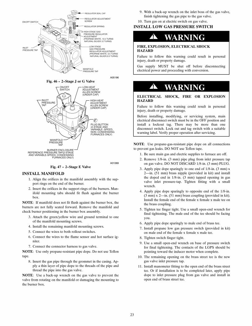
NOTE: For the 2--stage furnaces with a Series J and Series G gasvalve (see Fig. 46), they MUST have both regulator springsreplaced and the gas valve MUST be pre--adjusted.For older model 2--stage furnaces with a Series E gas valve (seeFig. 47), they DO NOT need to have the regulator springsreplaced in the gas valve, but the regulators in the gas valve mustbe pre--adjusted for propane applications.
For J and G valves See Fig. 29.1. Be sure main gas and electrical supplies are turned OFF.
2. Remove both regulator seal caps. See Fig. 29.
3. Remove both regulator adjustment screws.
4. Remove both natural gas regulator springs (silver).
5. Install propane gas regulator springs (white).
6. Install regulator adjustment screws.
7. Turn low--heat stage adjusting screw clockwise (inwards)9.5 turns. This will increase the manifold pressure closer tothe low--heat set point.
8. Turn high--heat stage adjusting screw clockwise (inwards)13.5 turns. This will increase the manifold pressure closerto the high--heat set point.
9. Do not install regulator seal caps at this time.
For E valves see Fig. 47.1. Be sure gas and electrical supplies to furnace are off.
2. Remove caps that conceal adjustment screws for high--and low--heat stage gas valve regulators. See Fig. 47.
3. Turn low--heat stage adjusting screw (3/32--in. [2 mm] hexAllen screw) clockwise (in) 1 full turn. This will increasethe manifold pressure closer to the propane low--heat setpoint.
4. Turn high--heat stage adjusting screw (3/32--in. [2 mm]hex Allen screw) clockwise (in) 2 full turns. This will in-crease the manifold pressure closer to the propane high--heat set point.
5. Do not install regulator seal caps at this time.
23
A05196
Fig. 46 -- 2--Stage J or G Valve
ON
OFF
ON/OFFSWITCH
INLETPRESSURETAP
BURNER ENCLOSUREREFERENCE PRESSURE TAP(2-STAGEAND VARIABLE-SPEED, CONDENSING
FURNACES ONLY)
MANIFOLDPRESSURE
TAP
LOW-HEATADJUSTMENTALLEN SCREW(UNDER CAP)
HIGH-HEATADJUSTMENTALLEN SCREW(UNDER CAP)
PLUG BUTTON(2-STAGE ANDVARIABLE–SPEED,NON–CONDENSINGFURNACES ONLY)
A01069
Fig. 47 -- 2--Stage E Valve
INSTALL MANIFOLD1. Align the orifices in the manifold assembly with the sup-
port rings on the end of the burner.
2. Insert the orifices in the support rings of the burners. Man-ifold mounting tabs should fit flush against the burnerbox.
NOTE: If manifold does not fit flush against the burner box, theburners are not fully seated forward. Remove the manifold andcheck burner positioning in the burner box assembly.
3. Attach the green/yellow wire and ground terminal to oneof the manifold mounting screws.
4. Install the remaining manifold mounting screws.
5. Connect the wires to both rollout switches.
6. Connect the wires to the flame sensor and hot surface ig-niter.
7. Connect the connector harness to gas valve.
NOTE: Use only propane-resistant pipe dope. Do not use Teflontape.
8. Insert the gas pipe through the grommet in the casing. Ap-ply a thin layer of pipe dope to the threads of the pipe andthread the pipe into the gas valve.
NOTE: Use a back-up wrench on the gas valve to prevent thevalve from rotating on the manifold or damaging the mounting tothe burner box.
9. With a back-up wrench on the inlet boss of the gas valve,finish tightening the gas pipe to the gas valve.
10. Turn gas on at electric switch on gas valve.
INSTALL LOW GAS PRESSURE SWITCH
FIRE, EXPLOSION, ELECTRICAL SHOCKHAZARD
Failure to follow this warning could result in personalinjury, death or property damage.
Gas supply MUST be shut off before disconnectingelectrical power and proceeding with conversion.
! WARNING
ELECTRICAL SHOCK, FIRE OR EXPLOSIONHAZARD
Failure to follow this warning could result in personalinjury, death or property damage.
Before installing, modifying, or servicing system, mainelectrical disconnect switch must be in the OFF position andinstall a lockout tag. There may be more than onedisconnect switch. Lock out and tag switch with a suitablewarning label. Verify proper operation after servicing.
! WARNING
NOTE: Use propane-gas-resistant pipe dope on all connectionsto prevent gas leaks. DO NOT use Teflon tape.
1. Be sure main gas and electric supplies to furnace are off.
2. Remove 1/8-in. (3 mm) pipe plug from inlet pressure tapon gas valve. DO NOT DISCARD 1/8-in. (3 mm) PLUG.
3. Apply pipe dope sparingly to one end of 1/8-in. (3 mm) x2—in. (51 mm) brass nipple (provided in kit) and installthe doped end in 1/8-in. (3 mm) tapped opening in gasvalve inlet pressure-tap. Tighten fitting with a smallwrench.
4. Apply pipe dope sparingly to opposite end of the 1/8-in.(3 mm) x 2—in. (51 mm) brass coupling (provided in kit).Install the female end of the female x female x male tee onthe brass coupling.
5. Tighten tee finger tight. Use a small open-end wrench forfinal tightening. The male end of the tee should be facingyou.
6. Apply pipe dope sparingly to male end of brass tee.
7. Install propane low gas pressure switch (provided in kit)on male end of the female x female x male tee.
8. Tighten switch finger tight.
9. Use a small open-end wrench on base of pressure switchfor final tightening. The contacts of the LGPS should bepointing toward the inducer motor when complete.
10. The remaining opening on the brass street tee is the newgas valve inlet pressure tap.
11. Install manometer fitting to the open end of the brass streettee. Or if installation is to be completed later, apply pipedope to inlet pressure plug from gas valve and install inopen end of brass street tee.

24
12. Check all fittings for leaks after gas supply has beenturned on.
FIRE AND EXPLOSION HAZARD
Failure to follow this warning could result in personal injuryand/or death.
NEVER test for gas leaks with an open flame. Use acommercially available soap solution made specifically forthe detection of leaks to check all connections. A fire orexplosion may result causing property damage, personalinjury or loss of life.
! WARNING
RISQUE D’EXPLOSION ET D’INCENDIE
Le fait de ne pas suivre cet avertissement pourrait entraîner desdommages corporels et / ou la mort.
Ne jamais examiner pour les fuites de gaz avec une flammevive. Utilisez plutôt un savon fait specifiquement pour ladétection des fuites de gaz pour verifier tous les connections.Un incendie ou une explosion peut entrainer des dommagesmatériels, des blessures ou la mort.
! AVERTISSEMENT
MODIFY PRESSURE SWITCH WIRING
UNIT OPERATION HAZARD
Failure to follow this caution may result in unit damage orimproper operation.
Label all wires prior to disconnection when servicingcontrols.
CAUTION!
D’EQUIPEMENT D’OPERATION
Toute erreur de câblage peut être une source de danger et depanne.
Lors des opérations d’entretien des commandes, étiquetertous les fils avant de les déconnecter.
PRUDENCE!
1. Locate the orange wire in the kit with an insulated straightfemale spade terminal and an insulated straight male ter-minal on the other end.
2. Connect the female terminal to a terminal on the Low GasPressure Switch.
3. Locate the orange wire in the kit with an insulated straightfemale spade terminal and an insulated female flag termin-al on the other end.
4. Connect both straight female terminals of the orange wiresto the terminals on the Low Gas Pressure Switch.
5. Disconnect orange wire from low--heat pressure switchLPS on inducer housing.
6. Connect the orange wire from the Low Heat PressureSwitch to the orange wire with the insulated male spadeterminal.
7. Connect the orange wire from the Low Gas PressureSwitch to the terminal on the Low Heat Pressure Switch.
8. Route orange wires along wire harness. If possible, securewith wire tie provided in kit.
CHECK INLET GAS PRESSURE
Model Plug
Setup Switches SW1, 1 thru 8
SW2 A/C Air FlowSetup SwitchesAC 1 through AC 3
OA
T PL9
A B C D
PL4
HU
MPL7
W2 Y1 DHUM
SW4
SW2
SW3
CommunicationConnection
24 VACHUM Output(0.5 AMPMAX)
SW3 Continuous Fan(CF) airflow setupswitches CF 1 throughCF 3
Outside Air Thermistor
SW4
A11471
Fig. 48 -- Furnace Control
UNIT DAMAGE HAZARD
Failure to follow this caution may result in unit damage.
DO NOT operate furnace more than one minute to checkinlet gas pressure, as conversion is not complete at this time.
CAUTION!
NOTE: This kit is to be used only when inlet gas pressure isbetween 12.0-in. W.C. and 13.6-in. W.C.
1. Verify manometer is connected to inlet pressure tap on gasvalve.
2. Turn on furnace power supply.
3. Turn gas supply manual shutoff valve to ON position.
4. Turn furnace gas valve switch to ON position.
5. Turn Setup Switch SW1--2 on furnace control ON. SeeFig. 48.
6. Jumper R--W/W1 and R--W2 thermostat connections oncontrol.
7. When main burners ignite, confirm inlet gas pressure isbetween 12.0-in. W.C. and 13.6-in. W.C.
8. Remove jumper across R-W/W1 and R-W2 thermostatconnections to terminate call for heat.
9. Turn furnace gas valve switch to OFF position.
10. Turn gas supply manual shutoff valve to OFF position.
11. Turn off furnace power supply.
12. Remove manometer.
13. Apply pipe dope sparingly to end of inlet gas pipe plugand install into unused end of 1/8 in. tee. Use a smallback--up wrench on tee when tightening gas inlet pipeplug. See Fig. 49.
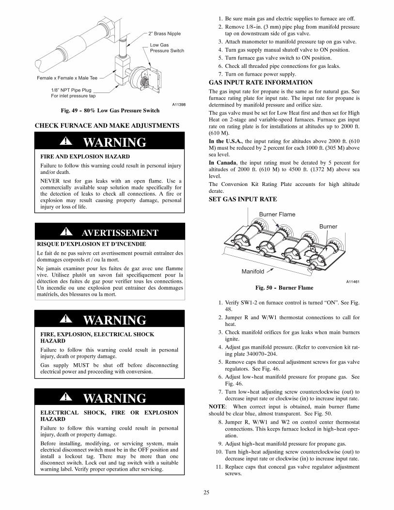
25
2” Brass Nipple
Low GasPressure Switch
Female x Female x Male Tee
1/8” NPT Pipe PlugFor inlet pressure tap
A11398
Fig. 49 -- 80% Low Gas Pressure Switch
CHECK FURNACE AND MAKE ADJUSTMENTS
FIRE AND EXPLOSION HAZARD
Failure to follow this warning could result in personal injuryand/or death.
NEVER test for gas leaks with an open flame. Use acommercially available soap solution made specifically forthe detection of leaks to check all connections. A fire orexplosion may result causing property damage, personalinjury or loss of life.
! WARNING
RISQUE D’EXPLOSION ET D’INCENDIE
Le fait de ne pas suivre cet avertissement pourrait entraîner desdommages corporels et / ou la mort.
Ne jamais examiner pour les fuites de gaz avec une flammevive. Utilisez plutôt un savon fait specifiquement pour ladétection des fuites de gaz pour verifier tous les connections.Un incendie ou une explosion peut entrainer des dommagesmatériels, des blessures ou la mort.
! AVERTISSEMENT
FIRE, EXPLOSION, ELECTRICAL SHOCKHAZARD
Failure to follow this warning could result in personalinjury, death or property damage.
Gas supply MUST be shut off before disconnectingelectrical power and proceeding with conversion.
! WARNING
ELECTRICAL SHOCK, FIRE OR EXPLOSIONHAZARD
Failure to follow this warning could result in personalinjury, death or property damage.
Before installing, modifying, or servicing system, mainelectrical disconnect switch must be in the OFF position andinstall a lockout tag. There may be more than onedisconnect switch. Lock out and tag switch with a suitablewarning label. Verify proper operation after servicing.
! WARNING
1. Be sure main gas and electric supplies to furnace are off.
2. Remove 1/8--in. (3 mm) pipe plug from manifold pressuretap on downstream side of gas valve.
3. Attach manometer to manifold pressure tap on gas valve.
4. Turn gas supply manual shutoff valve to ON position.
5. Turn furnace gas valve switch to ON position.
6. Check all threaded pipe connections for gas leaks.
7. Turn on furnace power supply.
GAS INPUT RATE INFORMATIONThe gas input rate for propane is the same as for natural gas. Seefurnace rating plate for input rate. The input rate for propane isdetermined by manifold pressure and orifice size.
The gas valve must be set for Low Heat first and then set for HighHeat on 2-stage and variable-speed furnaces. Furnace gas inputrate on rating plate is for installations at altitudes up to 2000 ft.(610 M).
In the U.S.A., the input rating for altitudes above 2000 ft. (610M) must be reduced by 2 percent for each 1000 ft. (305 M) abovesea level.
In Canada, the input rating must be derated by 5 percent foraltitudes of 2000 ft. (610 M) to 4500 ft. (1372 M) above sealevel.
The Conversion Kit Rating Plate accounts for high altitudederate.
SET GAS INPUT RATE
Burner Flame
Burner
ManifoldA11461
Fig. 50 -- Burner Flame
1. Verify SW1-2 on furnace control is turned “ON”. See Fig.48.
2. Jumper R and W/W1 thermostat connections to call forheat.
3. Check manifold orifices for gas leaks when main burnersignite.
4. Adjust gas manifold pressure. (Refer to conversion kit rat-ing plate 340070--204.
5. Remove caps that conceal adjustment screws for gas valveregulators. See Fig. 46.
6. Adjust low--heat manifold pressure for propane gas. SeeFig. 46.
7. Turn low--heat adjusting screw counterclockwise (out) todecrease input rate or clockwise (in) to increase input rate.
NOTE: When correct input is obtained, main burner flameshould be clear blue, almost transparent. See Fig. 50.
8. Jumper R, W/W1 and W2 on control center thermostatconnections. This keeps furnace locked in high--heat oper-ation.
9. Adjust high--heat manifold pressure for propane gas.
10. Turn high--heat adjusting screw counterclockwise (out) todecrease input rate or clockwise (in) to increase input rate.
11. Replace caps that conceal gas valve regulator adjustmentscrews.

26
NOTE: When correct input is obtained, main burner flameshould be clear blue, almost transparent. See Fig. 50.
12. Remove jumper across R, W1, and W2 after high--heat ad-justment to terminate call for heat.
13. Turn setup switch SW1-2 on furnace control to OFF posi-tion.
14. Turn furnace gas valve switch to OFF position.
15. Turn off furnace power supply.
16. Remove manometer and re-install manifold pressure tapplug.
17. Turn furnace gas valve switch to ON position.
18. Turn on furnace power supply.
19. Set room thermostat to call for heat.
20. Check pressure tap plug for gas leaks when main burnersignite.
21. Check for correct burner flame.
22. Observe unit operation through two complete heatingcycles.
23. See Sequence of Operation in furnace Installation, Start--Up, and Operating Instructions.
24. Set room thermostat to desired temperature.
25. After making the required manifold pressure adjustments,check and adjust the furnace temperature rise per the fur-nace installation instructions.
CHECK LOW GAS PRESSURE SWITCHThe newly installed low gas pressure switch is a safety deviceused to guard against adverse burner operating characteristics thatcan result from low gas supply pressure. Switch opens at not lessthan 7.2 in. W.C. and closes at not greater than 10.2 in. W.C.
This switch also prevents operation when the propane tank levelis low which can result in gas with a high concentration ofimpurities, additives, and residues that have settled to the bottomof the tank. Operation under these conditions can cause harm tothe heat exchanger system. This normally open switch closes
when gas is supplied to gas valve under normal operatingpressure. The closed switch completes control circuit. Should aninterruption or reduction in gas supply occur, the gas pressure atswitch drops below low gas pressure switch setting, and switchopens. Any interruption in control circuit (in which low gaspressure switch is wired) quickly closes gas valve and stops gasflow to burners. When normal gas pressure is restored, the systemmust be electrically reset to re--establish normal heating operation.
Before leaving installation, observe unit operation through twocomplete heating cycles. During this time, turn gas supply to gasvalve off just long enough to completely extinguish burner flame,then instantly restore full gas supply. To ensure proper low gaspressure switch operation, observe that there is no gas supply toburners until after hot surface igniter begins glowing.
LABEL APPLICATION1. Fill in Conversion Responsibility Label 340070--205 and
apply to Blower Access Door of furnace as shown. Date,name, and address of organization making this conversionare required.
2. Attach Conversion Rating Plate Label 340070--204 to out-er door of furnace.
3. Apply Gas Control Conversion Label: For 2--stage J andG gas valves, use Gas Control Conversion Label340070--202. (Do not use 340070--203, which is similar.)For 2--stage E gas valve, use Gas Control Adjustment La-bel 340070--203. (Do not use 340070--202, which is simil-ar.)
4. Replace control access door, blower access door and outerdoor of furnace.
CHECKOUT1. Observe unit operation through two complete heating
cycles.
2. See Sequence of Operation in furnace Installation, Start--Up, and Operating Instructions.
3. Set room thermostat to desired temperature.
A13198
Fig. 51 -- Conversion Responsibility Label
A13205
Fig. 52 -- Gas Control Conversion LabelA13206
Fig. 53 -- Gas Control Adjustment Label
Copyright 2013 CAC / BDP D 7310 W. Morris St. D Indianapolis, IN 46231
Manufacturer reserves the right to change, at any time, specifications and designs without notice and without obligations.
Catalog No: AG---KGBNPVSP---01
Replaces: AG--KGANPVSP--04
Edition Date: 08/13