installation instructions - commercial hvac · pdf filethis outdoor unit is designed for use...
TRANSCRIPT
10/2011 506148−01
����������� ����������Page 1
RETAIN THESE INSTRUCTIONSFOR FUTURE REFERENCE
IMPORTANTThe Clean Air Act of 1990 bans the intentional venting ofrefrigerant (CFCs, HCFCs AND HFCs) as of July 1,1992. Approved methods of recovery, recycling orreclaiming must be followed. Fines and/or incarcerationmay be levied for noncompliance.
WARNINGThis product and/or the indoor unit it is matched with maycontain fiberglass wool.
Disturbing the insulation during installation,maintenance, or repair will expose you to fiberglass wooldust. Breathing this may cause lung cancer. (Fiberglasswool is known to the State of California to cause cancer.)
Fiberglass wool may also cause respiratory, skin, andeye irritation.
To reduce exposure to this substance or for furtherinformation, consult material safety data sheets.
WARNINGImproper installation, adjustment, alteration, service ormaintenance can cause personal injury, loss of life, ordamage to property.
Installation and service must be performed by a licensedprofessional installer (or equivalent) or a service agency.
INSTALLATIONINSTRUCTIONS
T−CLASS� TPA Series7.5 AND 10 TON
HEAT PUMPS7.5 TO 10 TONS506148−01 10/2011Supersedes 06/11
Table of Contents
Shipping and Packing List 1. . . . . . . . . . . . . . . . . . . . . .
Outdoor Unit 1. . . . . . . . . . . . . . . . . . . . . . . . . . . . . . . . . .
Unit Dimensions, Corner Weights and Center ofGravities 2. . . . . . . . . . . . . . . . . . . . . . . . . . . . . . . . . . . . .
Unit Plumbing Parts Arrangement 3. . . . . . . . . . . . . . .
Unit Control Box Components Arrangement 4. . . . . . .
Model Number Identification 4. . . . . . . . . . . . . . . . . . . .
Rigging the Unit for Lifting 4. . . . . . . . . . . . . . . . . . . . . .
Installation Clearances 5. . . . . . . . . . . . . . . . . . . . . . . . .
Line Set 5. . . . . . . . . . . . . . . . . . . . . . . . . . . . . . . . . . . . . .
Refrigerant Charge and Check 8. . . . . . . . . . . . . . . . . .
System Operation 10. . . . . . . . . . . . . . . . . . . . . . . . . . . . .
Defrost System 10. . . . . . . . . . . . . . . . . . . . . . . . . . . . . . .
Defrost Control Board 10. . . . . . . . . . . . . . . . . . . . . . . . . .
Maintenance 11. . . . . . . . . . . . . . . . . . . . . . . . . . . . . . . . . .
Start−up and Performance Checklist 12. . . . . . . . . . . . . .
Shipping and Packing List
Check the unit for shipping damage and listed times beloware intact. If damaged, or if parts are missing, immediatelycontact the last shipping carrier.
1 � Assembled outdoor unit
1 � Installation instruction
Outdoor Unit
TPA series heat pumps, which will also be referred to in thisinstruction as the outdoor unit, uses HFC−410A refrigerant.This outdoor unit must be installed with a matching indoor
unit and line set as outlined in the TP EngineeringHandbook.
This outdoor unit is designed for use in thermal expansionvalve (TXV) systems only.
Litho U.S.A.

Page 2
Unit Dimensions, Corner Weights and Center of Gravities
TPA090S4S AND TPA120S4S
Corner Weights
Model No.AA BB CC DD
lbs. kg lbs. kg lbs. kg lbs. kg
TPA090S4S 105 48 105 48 112 51 112 51
TPA120S4S 129 59 110 50 123 56 145 66
Center of Gravities
Model No.EE FF
inch mm inch mm
TPA090S4S 21.75 552 29.0 737
TPA120S4S 20.0 508 28.25 718
9−1/8(232)
(29)
(54)
SUCTIONLINE
LIQUIDLINE
REFRIGERANT LINECONNECTIONS DETAIL
(29)(127)
BASE
REFRIGERANTLINE CONNECTIONS
SEE DETAIL
DISCHARGEAIR
41−3/8
60−1/8
(1470)
CONTROLBOX ACCESS
COMPRESSOR
DISCHARGEAIR
LIFTING HOLES(For Rigging)
FRONT VIEW
TOP VIEW
FORKLIFT SLOTS(Both Sides)
SIDE VIEW
(1108)
48−3/4(1238)
3−1/2(89)
(1149)
FFEE IN
LET
AIR
INLET AIR
BBAA
CCDD
CENTER OFGRAVITY
ELECTRICALINLETS (AboveRefrigerant Lines)
OUTDOORFAN GUARDS
INLET AIR
BASE
ELECTRICAL INLETS (AboveRefrigerant Lines)
OPTIONAL HAIL GUARD(Field Installed All Coil Sides)(Not used with Coil Guard)
OPTIONAL HAIL GUARD(Field Installed All Coil Sides)
(Not used with Coil Guard)
OPTIONALCOIL GUARD
(Field Installed All Coil Sides)(Not used with Hail Guard)
12(286)
(Not used withHail Guard)
OPTIONAL COIL GUARD(Field Installed All Coil Sides)
(Not used with Hail Guard)
OPTIONALCOIL GUARD(Field InstalledAll Coil Sides)
1−1/8
1−1/8
2−1/8
5
57−7/8(1051)
2 (51)
(1527)43−5/8
45−1/4

Page 3
TP SERIES
Unit Plumbing Parts Arrangement
TPA090S4S
SUCTION LINE SERVICEVALVE
LIQUID LINE SERVICEVALVE
COMPRESSOR
REVERSINGVALVE
LIQUID LINE BI−FLOW DRIER
COIL
HIGH PRESSURESWITCH (S4)
LOSS−OF−CHARGESWITCH (S24)
CTXV SENSING BULB
CHECK EXPANSIVE VALVE(CTXV)
DEFROST SWITCHLOCATION (S6)
TPA120S4S
LIQUID LINE BI−FLOW DRIER
LOSS OF CHARGE SWITCH(S24)
COMPRESSOR
HIGH PRESSURESWITCH (S4)
SUCTION LINE SERVICEVALVE
LIQUID LINE SERVICEVALVE
COIL
REVERSINGVALVE
CTXV SENSING BULBCTXV SENSING BULB
DEFROST SWITCHLOCATION (S6)
DEFROST SWITCHLOCATION (S9)
Page 4
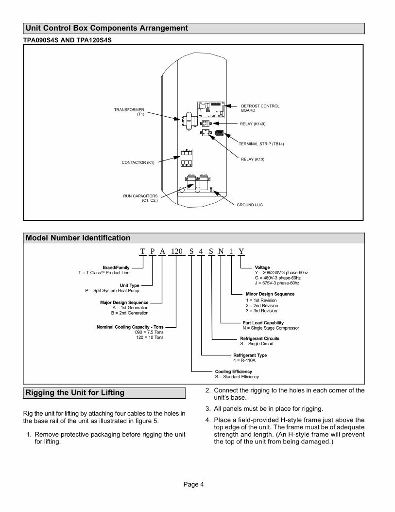
Unit Control Box Components Arrangement
TPA090S4S AND TPA120S4S
TRANSFORMER(T1)
CONTACTOR (K1)
RUN CAPACITORS(C1, C2,)
GROUND LUG
TERMINAL STRIP (TB14)
RELAY (K10)
RELAY (K149)
DEFROST CONTROLBOARD
Model Number Identification
T P A Y1120 S N4 S
Major Design SequenceA = 1st Generation
B = 2nd Generation
Brand/FamilyT = T−Class Product Line
Unit TypeP = Split System Heat Pump
Nominal Cooling Capacity − Tons090 = 7.5 Tons120 = 10 Tons
Cooling EfficiencyS = Standard Efficiency
Minor Design Sequence
1 = 1st Revision2 = 2nd Revision3 = 3rd Revision
VoltageY = 208/230V-3 phase-60hzG = 460V-3 phase-60hzJ = 575V-3 phase-60hz
Refrigerant Type4 = R−410A
Refrigerant CircuitsS = Single Circuit
Part Load CapabilityN = Single Stage Compressor
Rigging the Unit for Lifting
Rig the unit for lifting by attaching four cables to the holes inthe base rail of the unit as illustrated in figure 5.
1. Remove protective packaging before rigging the unitfor lifting.
2. Connect the rigging to the holes in each corner of theunit’s base.
3. All panels must be in place for rigging.
4. Place a field-provided H-style frame just above thetop edge of the unit. The frame must be of adequatestrength and length. (An H-style frame will preventthe top of the unit from being damaged.)

Page 5
TP SERIES
Caution − do notwalk on unit.
Lifting point should be directly above the center of gravity.
Important − all panelsmust be in place for
rigging.
Figure 1. TPA 090S4S and TPA 120S4S
Installation Clearances
See Unit Dimensions on page to sizing mounting slab,platforms or supports. Refer to figure 2 for mandatoryinstallation clearance requirements.
NOTES:
� Clearance to one of the remaining two sides may be
12 in. (305 mm) and the final side may be 6 in. (152mm).
� A clearance of 24 in. (610 mm) must be maintained
between two units.
� 48 in. (1219 mm) clearance required on top of unit.
ÏÏÏÏÏÏÏÏÏÏÏÏÏÏÏÏÏÏÏÏÏÏÏÏÏÏÏÏÏÏÏÏÏÏÏÏÏÏÏÏÏÏÏÏÏÏÏÏÏÏÏÏÏÏÏÏÏÏÏÏÏÏÏÏÏÏÏÏÏÏÏÏÏÏÏÏÏÏÏÏÏÏÏÏÏÏÏÏÏÏÏÏÏÏÏÏÏÏÏÏÏÏÏÏÏÏÏÏÏÏÏÏÏÏÏÏÏÏÏÏÏÏÏÏÏÏÏÏÏÏÏÏÏÏÏÏÏÏÏÏÏÏÏÏÏÏÏÏÏÏÏÏÏÏÏÏÏÏÏÏÏÏÏÏÏÏÏÏÏÏÏÏÏÏÏÏÏÏÏÏÏÏÏÏÏÏÏÏÏÏÏÏÏÏÏ
Note− 48 in. (1219 mm) clearance required above top of unit.
Figure 2. TPA 090S4S and TPA 120S4SInstallation Clearances
*One of these clearance distances may be reduced to 18 inches (457 mm).
**This clearance may be reduced to 12 inches (305 mm).
SEENOTES
36 (914)
30(762)
SEENOTES
Line Set
Field refrigerant piping consists of liquid and suction lines
connecting the condensing unit and the indoor unit. Liquid
and suction service valves are located in a compartment at
the corner of the unit below the control box. Piping can be
routed directly from the service valves or field supplied
elbows can be added to divert the piping as required
Refer to table 1 for field−fabricated refrigerant line sizes for
runs up to 50 linear feet (15 m).
Table 1. Refrigerant Line Sizes for Runs Up to 50 Linear Feet
Unit Liquid Line Suction Line
TPA 090 5/8" (16 mm) 1−3/8" (35 mm)
TPA 120 5/8" (16 mm) 1−3/8" (35 mm)
Refrigerant Line Limitations
You may install the unit in applications that have line setlengths of up to 50 linear feet (15 m) with refrigerant linesizes as outlined in table 1 (excluding equivalent length offittings). Size refrigerant lines greater than 50 linear feet(15m or greater) according to the Lennox Refrigerant
Piping Design and Fabrication Guidelines (Corp. 9351−L9)or latest version.
Electrical Connections
WARNINGElectric Shock Hazard. Can cause injuryor death.
Line voltage is present at all componentson units with single-pole contactors, evenwhen unit is not in operation!
Unit may have multiple power supplies.Disconnect all remote electric powersupplies before opening access panel.
Unit must be grounded in accordancewith national and local codes.
In the United States, wiring must conform with current localcodes and the current National Electric Code (NEC). InCanada, wiring must conform with current local codes andthe current Canadian Electrical Code (CEC).
TRANSFORMER − 24VAC, 70VA − PROVIDED
NOTE � The addition of accessories to the system couldexceed the 70VA power requirement of thefactory-provided transformer. Measure the system’scurrent and voltage after installation is complete todetermine transformer loading. If loading exceeds thefactory-provided transformer capacity, a largerfield-provided transformer will need to be installed in thesystem.

Page 6
DISCONNECTSWITCH
MAIN FUSEBOX/BREAKER
PANEL
Refer to the unit nameplate for minimum circuit ampacity amperageminimum, and maximum fuse or circuit breaker fusible (HACR perNEC). Install power wiring and properly sized disconnect switch.
NOTE � ANY EXCESS HIGH VOLTAGEFIELD WIRING SHOULD BE TRIMMEDAND SECURED AWAY FROM ANY LOWVOLTAGE FIELD WIRING.
NOTE � UNITS ARE APPROVED FOR USE ONLY WITH COPPER CONDUCTORS.GROUND UNIT AT DISCONNECT SWITCH OR TO AN EARTH GROUND.
CIRCUIT SIZING AND DISCONNECT SWITCH TYPICAL HIGH VOLTAGE POWER SUPPLYCONNECTIONS
USE THE LEFT CUTOUT TO ROUTEHIGH VOLTAGE WIRING TO THE K1CONTACTOR ON THE TPA 090S AND120S MODELS.
CONTROL BOX
HIGH VOLTAGE WIRING
K1 CONTACTOR
LEFT CUTOUT
CONNECT EARTH GROUND TOGROUND LUG
GROUND LUG
1 2
Install room thermostat (ordered separately) on an inside wallapproximately in the center of the conditioned area and 5 feet (1.5m)from the floor. It should not be installed on an outside wall or where itcan be affected by sunlight, drafts or vibrations. Install low voltage wiring from outdoor to indoor unit and from
thermostat to indoor unit as illustrated.
THERMOSTAT
5 FEET(1.5M)
INSTALL THERMOSTAT TYPICAL CONTROL WIRING
TPA HEATPUMP
C1
W1
C
R
C1
C
RO
TAA AIRHANDER
Y1
C
R
A2THERMOSTAT
RT2 REMOTESENSOR
S2
S1
W2
W
W2
W1
W2
3 4
NOTE � FOR PROPER VOLTAGES, SELECT THERMOSTAT WIRE (CONTROLWIRES) GAUGE PER TABLE ABOVE.
WIRE RUN LENGTH AWG# INSULATION TYPE
LESS THAN 100’ (30 METERS) 18 TEMPERATURE RATING
MORE THAN 100’ (30 METERS) 16 35ºC MINIMUM.
TYPICAL UNIT LOW VOLTAGE CONNECTIONS
NOTE � DO NOT BUNDLE ANY EXCESS 24VAC CONTROL WIRES INSIDECONTROL BOX.
NOTE � WIRE TIE PROVIDES LOW VOLTAGE WIRE STRAIN RELIEF AND TO MAINTAINSEPARATION OF FIELD INSTALLED LOW AND HIGH VOLTAGE CIRCUITS.
A Run control wires through right cutout.
B Run control wires through wire ties.
C Make control wire connections using fieldprovided wire nuts. See figure 3 forconnections requirements.
D Tighten wire tie to secure 24V low voltagecontrol wiring.
TIGHTEN WIRE TIES
RIGHT CUTOUT
ROUTE THROUGH WIRE TIES
K1 CONTACTOR
LOW VOLTAGE CONTROLWIRING
HIGH VOLTAGE WIRING
WIRE NUTS
EARTH GROUND CONNECTION
CONTROL BOX
A
B
D
C
5
Page 7
TP SERIES
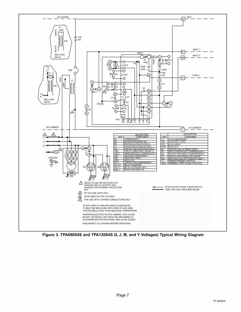
Figure 3. TPA090S4S and TPA120S4S G, J, M, and Y Voltages) Typical Wiring Diagram
Page 8
Refrigerant Charge and Check
TPA units have a factory holding charge of 1 pound ofHFC−410A. Additional refrigerant will need to be addedduring installation (table 2).
Table 2. Adding Refrigerant
Models25 Feet1
(pounds)
LiquidLine
Diameter(inches)
VaporLine
Diameter(inches)
Adjustment
per foot of
Line2
(Ounces)
TPA090 17 5/8 1−3/8 1.8
TPA120 23 5/8 1−3/8 1.8
1 Total amount of charge necessary to accommodate 25feet of line set.2 If line set length is greater than 25 feet, add this amount toeach circuit. If line set is less than 25 feet, subtract thisamount from each circuit. Refer to Lennox RefrigerantPiping Design and Fabrication Guidelines for moreinformation.
NOTE − Refrigerant line sets longer than 200 feet (60 meters)
are not recommended. For assistance contact LennoxApplication Department.
To charge the system, use either of the followingprocedures:
CHARGE PROCEDURE � NORMAL OPERATING
PRESSURES
1. Connect a manifold gauge set to the service valves:
A Low pressure gauge to vapor service port.
B High pressure gauge to liquid valve service port
2. Operate system in cooling mode until pressures andtemperatures stabilize (5 minutes minimum).
3. Use a thermometer to measure the outdoor ambienttemperature. The outdoor temperature will determinewhich charging procedure to use.
Outdoor Temp > 65ºF (18ºC)
1. Apply the outdoor ambient temperature to tables 4 or5 to determine normal operating pressures. Comparethe normal operating pressures to the pressuresobtained from the connected gauges. If dischargepressure is high, remove refrigerant from the system.If discharge pressure is low, add refrigerant to thesystem.
A Add or remove charge in increments.
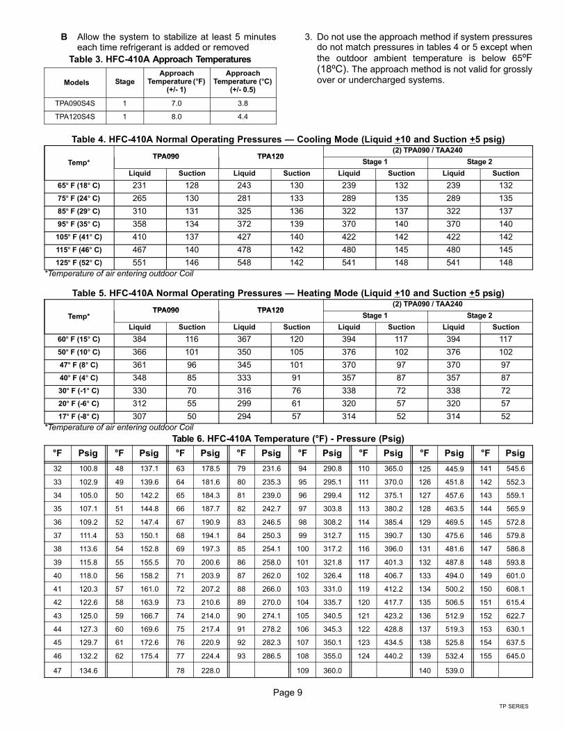
B Allow the system to stabilize at least 5 minuteseach time refrigerant is added or removed
2. Minor variations in these pressures may be expecteddue to differences in installations. Significant differencescould mean that the system is not properly charged orthat a problem exists with some component in thesystem.
3. Switch to heating mode to confirm normal operatingpressures. Let the system stabilize at least 10 minutesthen compare the pressure obtained from the
connected gauges to the normal operating pressures(heating mode) in table 5.
4. Verify the charge, as described in the approachmethod section.
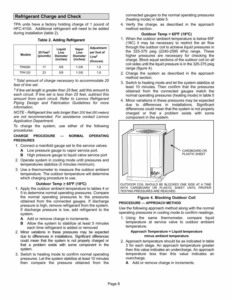
Outdoor Temp < 65ºF (18ºC)
1. When the outdoor ambient temperature is below 65F(18C) it may be necessary to restrict the air flowthrough the outdoor coil to achieve liquid pressures inthe 325−375 psig (2240−2585 kPa) range. Thesehigher pressures are necessary for checking thecharge. Block equal sections of the outdoor coil on allcoil sides until the liquid pressure is in the 325−375 psigrange (figure 4).
2. Charge the system as described in the approachmethod section.
3. Switch to heating mode and let the system stabilize atleast 10 minutes. Then confirm that the pressuresobtained from the connected gauges match thenormal operating pressures (heating mode) in table 5
4. Minor variations in these pressures may be expecteddue to differences in installations. Significantdifferences could mean that the system is not properlycharged or that a problem exists with somecomponent in the system.
CARDBOARD ORPLASTIC SHEET
OUTDOOR COIL SHOULD BE BLOCKED ONE SIDE AT A TIMEWITH CARDBOARD OR PLASTIC SHEET UNTIL PROPERTESTING PRESSURES ARE REACHED.
Figure 4. Blocking Outdoor Coil
PROCEDURE � APPROACH METHOD
Use the following approach method along with the normaloperating pressures in cooling mode to confirm readings.
1. Using the same thermometer, compare liquidtemperature at service valve to outdoor ambienttemperature.
Approach Temperature = Liquid temperature
minus ambient temperature
2. Approach temperature should be as indicated in table3 for each stage. An approach temperature greaterthen this value indicates an undercharge. An approachtemperature less than this value indicates anovercharge.
A Add or remove charge in increments.
Page 9
TP SERIES
B Allow the system to stabilize at least 5 minuteseach time refrigerant is added or removed
Table 3. HFC−410A Approach Temperatures
Models StageApproach
Temperature (�F)(+/− 1)
ApproachTemperature (�C)
(+/− 0.5)
TPA090S4S 1 7.0 3.8
TPA120S4S 1 8.0 4.4
3. Do not use the approach method if system pressuresdo not match pressures in tables 4 or 5 except when
the outdoor ambient temperature is below 65ºF(18ºC). The approach method is not valid for grosslyover or undercharged systems.
Table 4. HFC−410A Normal Operating Pressures � Cooling Mode (Liquid +10 and Suction +5 psig)
Temp*TPA090 TPA120
(2) TPA090 / TAA240TPA090 TPA120
Stage 1 Stage 2
Liquid Suction Liquid Suction Liquid Suction Liquid Suction
65� F (18� C) 231 128 243 130 239 132 239 132
75� F (24� C) 265 130 281 133 289 135 289 135
85� F (29� C) 310 131 325 136 322 137 322 137
95� F (35� C) 358 134 372 139 370 140 370 140
105� F (41� C) 410 137 427 140 422 142 422 142
115� F (46� C) 467 140 478 142 480 145 480 145
125� F (52� C) 551 146 548 142 541 148 541 148
*Temperature of air entering outdoor Coil
Table 5. HFC−410A Normal Operating Pressures � Heating Mode (Liquid +10 and Suction +5 psig)
Temp*TPA090 TPA120
(2) TPA090 / TAA240TPA090 TPA120
Stage 1 Stage 2
Liquid Suction Liquid Suction Liquid Suction Liquid Suction
60� F (15� C) 384 116 367 120 394 117 394 117
50� F (10� C) 366 101 350 105 376 102 376 102
47� F (8� C) 361 96 345 101 370 97 370 97
40� F (4� C) 348 85 333 91 357 87 357 87
30� F (−1� C) 330 70 316 76 338 72 338 72
20� F (−6� C) 312 55 299 61 320 57 320 57
17� F (−8� C) 307 50 294 57 314 52 314 52
*Temperature of air entering outdoor Coil
Table 6. HFC−410A Temperature (°F) − Pressure (Psig)
°F Psig °F Psig °F Psig °F Psig °F Psig °F Psig °F Psig °F Psig
32 100.8 48 137.1 63 178.5 79 231.6 94 290.8 110 365.0 125 445.9 141 545.6
33 102.9 49 139.6 64 181.6 80 235.3 95 295.1 111 370.0 126 451.8 142 552.3
34 105.0 50 142.2 65 184.3 81 239.0 96 299.4 112 375.1 127 457.6 143 559.1
35 107.1 51 144.8 66 187.7 82 242.7 97 303.8 113 380.2 128 463.5 144 565.9
36 109.2 52 147.4 67 190.9 83 246.5 98 308.2 114 385.4 129 469.5 145 572.8
37 111.4 53 150.1 68 194.1 84 250.3 99 312.7 115 390.7 130 475.6 146 579.8
38 113.6 54 152.8 69 197.3 85 254.1 100 317.2 116 396.0 131 481.6 147 586.8
39 115.8 55 155.5 70 200.6 86 258.0 101 321.8 117 401.3 132 487.8 148 593.8
40 118.0 56 158.2 71 203.9 87 262.0 102 326.4 118 406.7 133 494.0 149 601.0
41 120.3 57 161.0 72 207.2 88 266.0 103 331.0 119 412.2 134 500.2 150 608.1
42 122.6 58 163.9 73 210.6 89 270.0 104 335.7 120 417.7 135 506.5 151 615.4
43 125.0 59 166.7 74 214.0 90 274.1 105 340.5 121 423.2 136 512.9 152 622.7
44 127.3 60 169.6 75 217.4 91 278.2 106 345.3 122 428.8 137 519.3 153 630.1
45 129.7 61 172.6 76 220.9 92 282.3 107 350.1 123 434.5 138 525.8 154 637.5
46 132.2 62 175.4 77 224.4 93 286.5 108 355.0 124 440.2 139 532.4 155 645.0
47 134.6 78 228.0 109 360.0 140 539.0

Page 10
System Operation
The outdoor unit and indoor blower cycle on demand fromthe room thermostat. When the thermostat blower switchis in the ON position, the indoor blower operatescontinuously.
HIGH PRESSURE SWITCHES (S4 AND S7)
These units are equipped with a auto-reset high pressureswitch (single−pole, single−throw) which is located on the
discharge line. The switch shuts off the compressor whendischarge pressure rises above the factory setting. HighPressure (auto reset) − trip at 640 psig, reset at 512 psig.
LOSS−OF−CHARGE SWITCH (S24)
These units are equipped with a loss−of−charge switch thatis located on the liquid line. The switch is a SPST,
auto−reset switch that is normally closed. The switchopens at 40 psi and closes at 90 psi.
Defrost System
The defrost system includes a defrost thermostat and adefrost control.
DEFROST THERMOSTAT
The defrost thermostat is located on the liquid line betweenthe check/expansion valve and the distributor on each coil.When the defrost thermostat senses 42°F (5.5°C) orcooler, its contacts close and send a signal to the defrostcontrol board to start the defrost timing. It also terminates
defrost when the liquid line warms up to 70°F (21°C).
DEFROST CONTROL
The defrost control board includes the combined functionsof a time/temperature defrost control, defrost relay, timedelay, diagnostic LEDs, and a terminal strip for field wiringconnections.
The control provides automatic switching from normalheating operation to defrost mode and back. Duringcompressor cycle (defrost thermostat is closed, calling fordefrost), the control accumulates compressor run times at30, 60, or 90 minute field adjustable intervals. If the defrostthermostat is closed when the selected compressor runtime interval ends, the defrost relay is energized and
defrost begins.
Each timing pin selection provides a different accumulatedcompressor run time period for one defrost cycle. This timeperiod must occur before a defrost cycle is initiated. Thedefrost interval can be adjusted to 30 (T1), 60 (T2), or 90(T3) minutes. The maximum defrost period is 14 minutesand cannot be adjusted.
NOTE � Defrost control part number is listed near the P1
timing pins.
� Units with defrost control 100269−02: Factory defaultis 60 minutes.
� Units with defrost control 100269−04: Factory defaultis 90 minutes
If the timing selector jumper is missing, the defrost control
defaults to a 90−minute defrost interval.
Defrost Control Board
DEFROST CONTROL TIMING PINS
24V TERMINALSTRIPCONNECTIONS
DIAGNOSTICLEDS
HIGH PRESSURESWITCH
TESTPINS
FIELD SELECTTIMING PINS
REVERSINGVALVE
DEFROSTTHERMOSTAT
LOSS−OF−CHARGESWITCH
COMPRESSORDELAY PINS
S4
S24
SERVICE LIGHTCONNECTIONS
Figure 5. Outdoor Unit Defrost Control Board
A TEST option is provided for troubleshooting. The TESTmode may be started any time the unit is operating inthe heating mode and the defrost thermostat is closedor jumpered. If the jumper is in the TEST position atpower-up, the control will ignore the test pins. When thejumper is placed across the TEST pins for two seconds,
the control will enter the defrost mode. If the jumper isremoved before an additional 5−second period haselapsed (7 seconds total), the unit will remain in defrostmode until the defrost thermostat opens or 14 minuteshave passed. If the jumper is not removed until after theadditional 5−second period has elapsed, the defrost will
terminate and the test option will not function again until thejumper is removed and re−applied.
COMPRESSOR DELAY
The defrost board has a field−selectable function to reduceoccasional sounds that may occur while the unit is cyclingin and out of the defrost mode. When the compressor
delay jumper is removed, the compressor will be cycled offfor 30 seconds going in and out of the defrost mode.
NOTE � The 30-second compressor feature is ignoredwhen the TEST pins have been jumpered.
TIME DELAY
The timed−off delay is five minutes long. The delay helpsprotect the compressor from short−cycling in case thepower to the unit is interrupted or a pressure switch opens.
The delay is bypassed by placing the timer select jumperacross the TEST pins for 0.5 seconds.
NOTE � The board must have a thermostat demand forthe bypass function.

Page 11
TP SERIES
PRESSURE SWITCH CIRCUITS
The defrost control includes two pressure switch circuits.The factory−installed high pressure switch (S4) wires areconnected to the board’s HI PS terminals (figure 5). Theboard also includes LO PS terminals to accommodate the
factory installed loss−of−charge switch.
During a single thermostat cycle, the defrost control will
lock out the unit after the fifth time that the circuit isinterrupted by any pressure switch that is wired to thecontrol board. In addition, the diagnostic LEDs will indicatea pressure switch lockout after the fifth occurrence of anopen pressure switch (table 7). The unit will remain lockedout until power is broken then remade to the control or untilthe jumper is applied to the TEST pins for 0.5 seconds.
NOTE � The defrost control board ignores input from theloss−of−charge switch terminals during the TEST mode,during the defrost cycle, during the 90−second start−upperiod, and for the first 90 seconds each time the reversingvalve switches heat/cool modes. If the TEST pins arejumpered and the 5−minute delay is being bypassed,the LO PS terminal signal is not ignored during the90−second start−up period.
SERVICE LIGHT CONNECTION
The defrost control board includes terminal connectionsfor a service light which provides a signal that activates theroom thermostat service light during periods of inefficientoperation.
IMPORTANTAfter testing has been completed, properly repositiontest jumper across desired timing pins.
DIAGNOSTIC LEDS
The defrost board uses two LEDs for diagnostics. TheLEDs flash a specific sequence according to the diagnosis(table 7).
Table 7. Defrost Control Board Diagnostic LEDs
DS2 Green DS1 Red Condition
OFF OFF Power problem
Simultaneous Slow Flash Normal operation
Alternating Slow Flash 5−min. anti−short cycle delay
Fault and Lockout Codes
OFF Slow Flash Loss−of−Charge Fault
OFF ON Loss−of−Charge Lockout
Slow Flash OFF High Pressure Fault
ON OFF High Pressure Lockout
Maintenance
At the beginning of each cooling season, the system
should be checked as follows:
OUTDOOR UNIT
1. Clean and inspect the condenser coil. You can flushthe coil with a water hose.
2. The outdoor fan motor is prelubricated and sealed. Nofurther lubrication is necessary.
3. Visually inspect connecting lines and coils forevidence of oil leaks.
4. Check wiring for loose connections.
5. Check for correct voltage at the unit while the unit isoperating and while it is off.
6. Check amp−draw of the outdoor fan motor.
Unit Nameplate _________ Actual ____________
7. Check amp−draw of the compressor.
Unit Nameplate _________ Actual ____________
NOTE − If the owner complains of insufficient cooling,
gauge the unit and check the refrigerant charge. Refer to
section on refrigerant charging in this instruction.
INDOOR COIL
1. If necessary, clean the coil.
2. Check connecting lines and coils for evidence of oilleaks.
3. If necessary, check the condensate line and clean it.
INDOOR UNIT
1. Clean or change filters.
2. Adjust the blower speed for cooling. Measure thepressure drop over the coil to determine the correctblower CFM. Refer to the unit information servicemanual for pressure drop tables and procedure.
3. On belt drive blowers, check the belt for wear andproper tension.
4. Check all wiring for loose connections.
5. Check for correct voltage at the unit (bloweroperating).
6. Check amp−draw on blower motor.
Unit Nameplate _________ Actual ____________
WARNINGElectric shock hazard. Can cause injury ordeath. Before attempting to perform anyservice or maintenance, turn the electricalpower to unit OFF at disconnectswitch(es). Unit may have multiple powersupplies.

Page 12
Start−Up and Performance Checklist
Job Name Job no. Date
Job Location City State
Installer City State
Unit Model No. Serial No. Service Technician
Nameplate Voltage
Rated Load Ampacity Compressor Amperage:
Maximum Fuse or Circuit Breaker
Electrical Connections Tight? � Indoor Filter clean? � Supply Voltage (Unit Off)
Indoor Blower RPM S.P. Drop Over Indoor (Dry) Outdoor Coil Entering Air Temp.
Vapor Pressure;
Refrigerant Lines: Leak Checked? � Properly Insulated? � Outdoor Fan Checked? �
Service Valves: Fully Opened? � Caps Tight? � Voltage With Compressor Operating
SEQUENCE OF OPERATION
Calibrated? �
THERMOSTAT
Properly Set? � Level? �Heating Correct? � Cooling Correct? �