installation instructions applications: 1965 - 1966 …
TRANSCRIPT
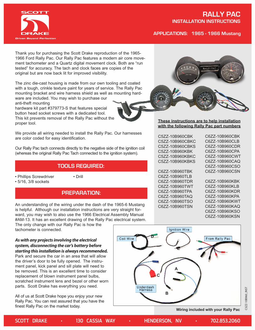
Thank you for purchasing the Scott Drake reproduction of the 1965-1966 Ford Rally Pac. Our Rally Pac features a modern air core move-ment tachometer and a Quartz digital movement clock. Both are “run tested” for accuracy. The tach and clock faces are copies of the original but are now back lit for improved visibility.
The zinc die-cast housing is made from our own tooling and coated with a tough, crinkle texture paint for years of service. The Rally Pac mounting bracket and wire harness shield as well as mounting hard-ware are included. You may wish to purchase our anti-theft mounting hardware kit part #379773-S that features special button head socket screws with a dedicated tool. This kit prevents removal of the Rally Pac without the proper tool.
We provide all wiring needed to install the Rally Pac. Our harnesses are color coded for easy identification.
Our Rally Pac tach connects directly to the negative side of the ignition coil (whereas the original Rally Pac Tach connected to the ignition system).
TOOLS REQUIRED:
• Phillips Screwdriver• 5/16, 3/8 sockets
• Drill
PREPARATION:
An understanding of the wiring under the dash of the 1965-6 Mustang is helpful. Although our installation instructions are very straight for-ward, you may wish to also use the 1966 Electrical Assembly Manual #AM-13. It has an excellent drawing of the Rally Pac electrical system. The only change with our Rally Pac is how the tachometer is connected.
As with any projects involving the electrical system, disconnecting the car’s battery before starting this installation is always recommended. Park and secure the car in an area that will allow the driver’s door to be fully opened. The instru-ment panel, kick panel and sill plate will need to be removed. This is an excellent time to consider replacement of blown instrument panel bulbs, scratched instrument lens and bezel or other worn parts. Scott Drake has everything you need.
All of us at Scott Drake hope you enjoy your new Rally Pac. You can rest assured that you have the finest Rally Pac on the market today.
RALLY PACINSTALLATION INSTRUCTIONS
APPLICATIONS: 1965 - 1966 Mustang
C5ZZ
-10B
960_
INST
Wiring included with your Rally Pac
A
B
C
D
E
C5ZZ-10B960CBK C5ZZ-10B960CBKCC5ZZ-10B960CBKSC5ZZ-10B960KBKC5ZZ-10B960KBKCC5ZZ-10B960KBKS
C6ZZ-10B960TBKC6ZZ-10B960TLBC6ZZ-10B960TDRC6ZZ-10B960TWTC6ZZ-10B960TPAC6ZZ-10B960TAQC6ZZ-10B960TSOC6ZZ-10B960TSN
C6ZZ-10B960CBKC6ZZ-10B960CLBC6ZZ-10B960CDRC6ZZ-10B960CPAC6ZZ-10B960CWTC6ZZ-10B960CAQC6ZZ-10B960CSOC6ZZ-10B960CSN
C6ZZ-10B960KBKC6ZZ-10B960KLBC6ZZ-10B960KDRC6ZZ-10B960KPAC6ZZ-10B960KWTC6ZZ-10B960KAQC6ZZ-10B960KSOC6ZZ-10B960KSN
These instructions are to help installationwith the following Rally Pac part numbers
SCOTT DRAKE • 130 CASSIA WAY • HENDERSON, NV • 702.853.2060
Consider the underdash harness we provide as an extension har-ness. Power for the clock and lights in the clock and tach need to be brought to the steering column area. Ford used the door light circuit for constant power for the clock (you can refer to the 1966 Electrical Assembly Manual #AM-13 to familiarize yourself with the wiring behind the instrument panel). All Mustangs have an instrument panel light circuit lead under the dash that is controlled by the headlamp switch. This is a large red plug with blue/red wire located near the igni-tion. Note: our underdash harness has a connector that looks the same.
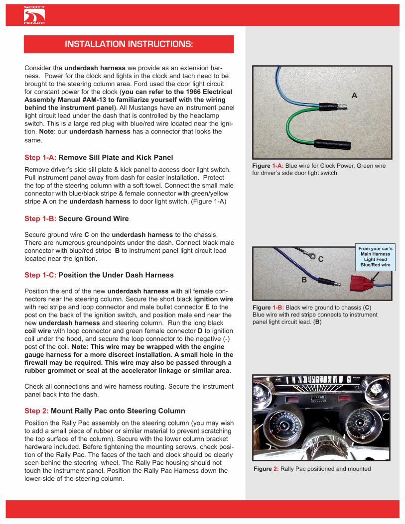
Step 1-A: Remove Sill Plate and Kick PanelRemove driver’s side sill plate & kick panel to access door light switch. Pull instrument panel away from dash for easier installation. Protect the top of the steering column with a soft towel. Connect the small male connector with blue/black stripe & female connector with green/yellow stripe A on the underdash harness to door light switch. (Figure 1-A)
Step 1-B: Secure Ground Wire
Secure ground wire C on the underdash harness to the chassis. There are numerous groundpoints under the dash. Connect black male connector with blue/red stripe B to instrument panel light circuit lead located near the ignition.
Step 1-C: Position the Under Dash Harness Position the end of the new underdash harness with all female con-nectors near the steering column. Secure the short black ignition wire with red stripe and loop connector and male bullet connector E to the post on the back of the ignition switch, and position male end near the new underdash harness and steering column. Run the long black coil wire with loop connector and green female connector D to ignition coil under the hood, and secure the loop connector to the negative (-) post of the coil. Note: This wire may be wrapped with the engine gauge harness for a more discreet installation. A small hole in the firewall may be required. This wire may also be passed through a rubber grommet or seal at the accelerator linkage or similar area.
Check all connections and wire harness routing. Secure the instrument panel back into the dash.
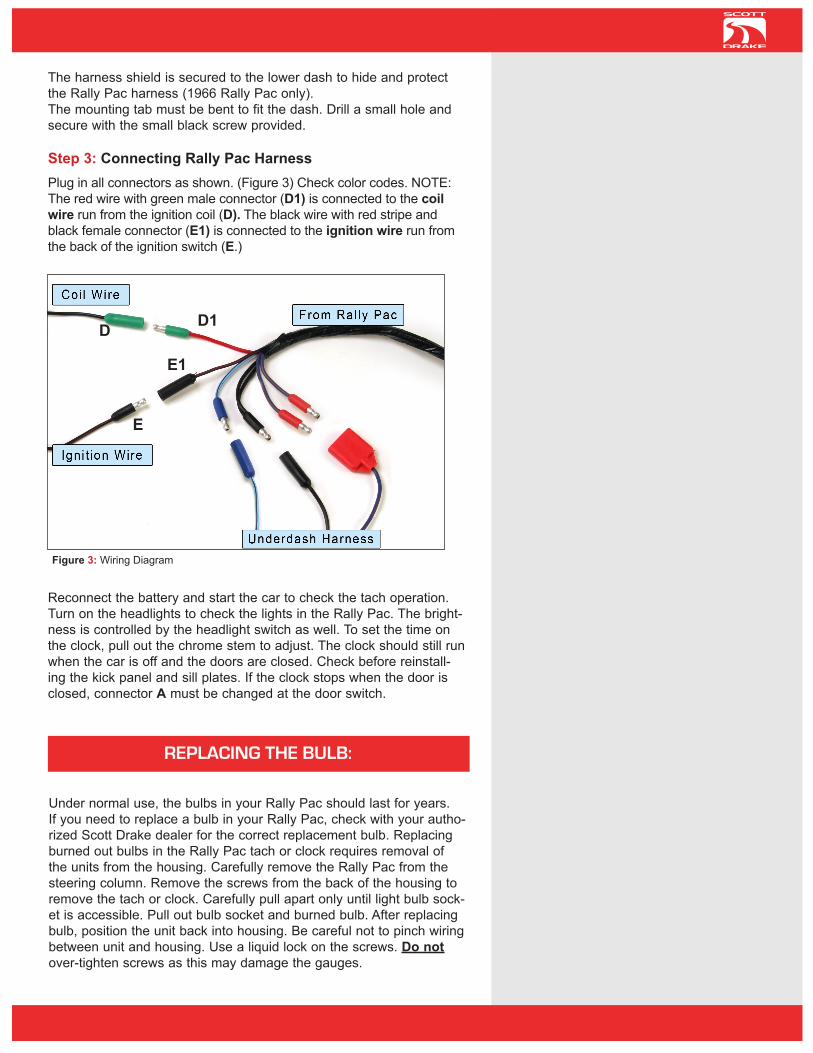
Step 2: Mount Rally Pac onto Steering ColumnPosition the Rally Pac assembly on the steering column (you may wish to add a small piece of rubber or similar material to prevent scratching the top surface of the column). Secure with the lower column bracket hardware included. Before tightening the mounting screws, check posi-tion of the Rally Pac. The faces of the tach and clock should be clearly seen behind the steering wheel. The Rally Pac housing should not touch the instrument panel. Position the Rally Pac Harness down the lower-side of the steering column.
Figure 1-A: Blue wire for Clock Power, Green wire for driver’s side door light switch.
A
Figure 2: Rally Pac positioned and mounted
Figure 1-B: Black wire ground to chassis (C) Blue wire with red stripe connects to instrument panel light circuit lead. (B)
From your car’sMain Harness
Light FeedBlue/Red wire
C
B
INSTALLATION INSTRUCTIONS:
The harness shield is secured to the lower dash to hide and protect the Rally Pac harness (1966 Rally Pac only). The mounting tab must be bent to fit the dash. Drill a small hole and secure with the small black screw provided.
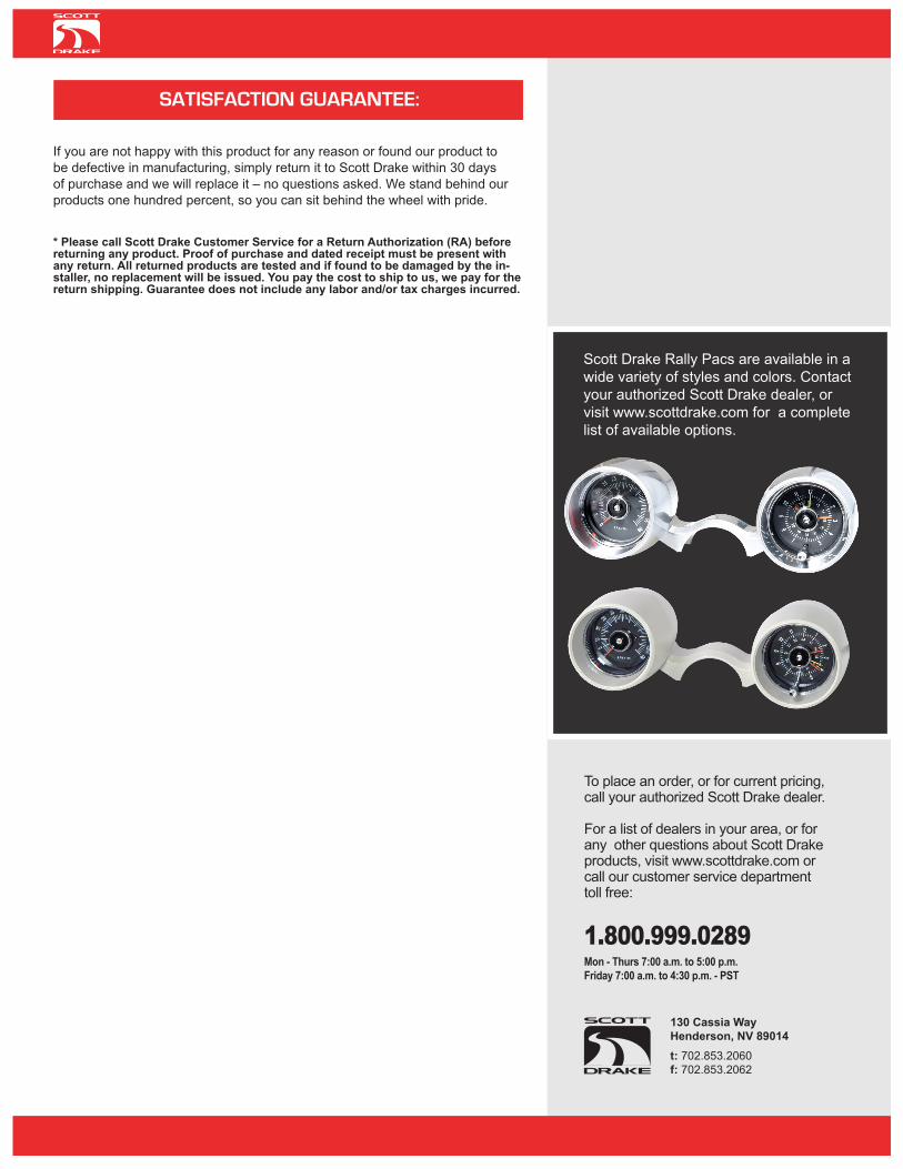
Step 3: Connecting Rally Pac HarnessPlug in all connectors as shown. (Figure 3) Check color codes. NOTE: The red wire with green male connector (D1) is connected to the coil wire run from the ignition coil (D). The black wire with red stripe and black female connector (E1) is connected to the ignition wire run from the back of the ignition switch (E.)
Reconnect the battery and start the car to check the tach operation. Turn on the headlights to check the lights in the Rally Pac. The bright-ness is controlled by the headlight switch as well. To set the time on the clock, pull out the chrome stem to adjust. The clock should still run when the car is off and the doors are closed. Check before reinstall-ing the kick panel and sill plates. If the clock stops when the door is closed, connector A must be changed at the door switch.
REPLACING THE BULB:
Under normal use, the bulbs in your Rally Pac should last for years. If you need to replace a bulb in your Rally Pac, check with your autho-rized Scott Drake dealer for the correct replacement bulb. Replacing burned out bulbs in the Rally Pac tach or clock requires removal of the units from the housing. Carefully remove the Rally Pac from the steering column. Remove the screws from the back of the housing to remove the tach or clock. Carefully pull apart only until light bulb sock-et is accessible. Pull out bulb socket and burned bulb. After replacing bulb, position the unit back into housing. Be careful not to pinch wiring between unit and housing. Use a liquid lock on the screws. Do not over-tighten screws as this may damage the gauges.
E
Figure 3: Wiring Diagram
E1
D1D
If you are not happy with this product for any reason or found our product to be defective in manufacturing, simply return it to Scott Drake within 30 days of purchase and we will replace it – no questions asked. We stand behind our products one hundred percent, so you can sit behind the wheel with pride.
* Please call Scott Drake Customer Service for a Return Authorization (RA) before returning any product. Proof of purchase and dated receipt must be present with any return. All returned products are tested and if found to be damaged by the in-staller, no replacement will be issued. You pay the cost to ship to us, we pay for the return shipping. Guarantee does not include any labor and/or tax charges incurred.
SATISFACTION GUARANTEE:
130 Cassia WayHenderson, NV 89014t: 702.853.2060f: 702.853.2062
To place an order, or for current pricing, call your authorized Scott Drake dealer.
For a list of dealers in your area, or for any other questions about Scott Drake products, visit www.scottdrake.com or call our customer service department toll free:
1.800.999.0289Mon - Thurs 7:00 a.m. to 5:00 p.m.Friday 7:00 a.m. to 4:30 p.m. - PST
Scott Drake Rally Pacs are available in a wide variety of styles and colors. Contact your authorized Scott Drake dealer, or visit www.scottdrake.com for a complete list of available options.