installation instructions and user guide · from the underside of the cold water storage tank to...
TRANSCRIPT
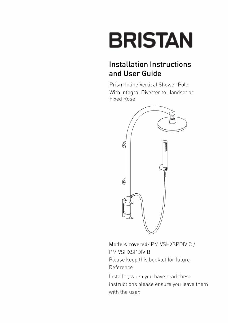
Installation Instructions
and User Guide
Prism Inline Vertical Shower Pole
With Integral Diverter to Handset or Fixed Rose
Models covered:Models covered:Models covered:Models covered: PM VSHXSPDIV C /
PM VSHXSPDIV B
Please keep this booklet for future
Reference.
Installer, when you have read these
instructions please ensure you leave them
with the user.
Contents
Thank you for choosing Bristan, the UK’s leading taps and showers expert. We have
designed this product with your enjoyment in mind. To ensure that it works to its
full potential, it needs to be fitted correctly. These fitting instructions have been
created to give you all of the information you need and, if you need any further help,
please do not hesitate to give us a call on 0844 701 6273.
Important Safety Information …………………………………………..
General Information ………………………………………………………………
Product Features …………………………………………………………………..
Dimensions ……………………………………………………………………………
Specifications ………………………………………………………………………..
Pack Contents ……………………………………………………………………….
3
4
5
6
7
8Pack Contents ……………………………………………………………………….
Installation Requirements ……………………………………………………..
Prior to Installation …………………………………………………………………
Installation ………………………………………………………………………………
Operation & Temperature Setting ………………………………………….
Maintenance ……………………………………………………………………………
Map of Hard Water Regions in the UK ……………………………………
Troubleshooting ……………………………………………………………………..
Guarantee …………………………………………………………………………….
8
9-11
12
12-16
17
18
19
20-21
22-23
2 Need help? Need help? Need help? Need help? Give us a call on 0844 701 6273 0844 701 6273 0844 701 6273 0844 701 6273 and speak to one of our trained advisors.

• Please read these instructions thoroughly and retain for future use.
• All products manufactured and supplied by Bristan are safe provided they are installed,
used correctly and receive regular maintenance in accordance with these instructions.
• This fitting needs to be installed in accordance with, and meet the requirements of the
Water Supply (Water Fittings) Regulations 1999 and Scottish Byelaws 2004.
• If you are in any doubt about your ability to install this product safely you must If you are in any doubt about your ability to install this product safely you must If you are in any doubt about your ability to install this product safely you must If you are in any doubt about your ability to install this product safely you must
employ the services of an experienced qualified plumber. employ the services of an experienced qualified plumber. employ the services of an experienced qualified plumber. employ the services of an experienced qualified plumber.
• Do not use if the showerhead or shower hose has been damaged or is blocked.
• Do not crush or kink the shower hose, this could damage the hose and cause leaks.
• Remove all packaging and check the components for damage before starting
installation.
• Warning: Warning: Warning: Warning: Before starting any installation please consider the following: Prior to
drilling into walls, check that there are no hidden electrical wires, cables or water
supply pipes. This can be checked with the aid of an electronic detector.
Important Safety Information
supply pipes. This can be checked with the aid of an electronic detector.
• If power tools are used do not forget to: - Wear eye protection
- Unplug equipment after use
• The fitting of isolating valves is required as close as is practical to the supply inlet
feeds of the thermostatic mixing valve.
• The fitting of strainers is recommended as close as is practical to the water supply
inlets of the thermostatic mixing valve.
• Warning: Warning: Warning: Warning: Before installing the new shower valve it is essential that you
thoroughly flush through the pipework in order to remove any remaining swarf, solder,
etc. Failure to carry out this procedure could cause problems or damage to the
workings of the shower valve.
• This product must not must not must not must not be modified in any way as this will invalidate the guarantee.
3Need help? Need help? Need help? Need help? Give us a call on 0844 701 6273 0844 701 6273 0844 701 6273 0844 701 6273 and speak to one of our trained advisors.

General Information
This product has been designed to comply with the BS EN 1287:1999 (LP) and BS EN
1111:1999 (HP) thermostatic mixing valve standards and satisfies the requirements of the
Water Supply (Water Fittings) Regulations 1999 and the Scottish Byelaws 2004.
BS6700 recommends the temperature of stored water should never exceed 65ºC. A
stored water temperature of 60ºC is considered sufficient to meet all normal
requirements and will minimise the build up of lime scale in hard water areas (see Map
of Hard Water Regions in the UK on page 19).
If the fitting is installed at low pressure (tank fed), then the minimum distance from the
highest installed position of the showerhead to the underside of the cold tank should be
at least 10 metres to ensure adequate performance.
Note: Note: Note: Note: Nominally equal (balanced) inlet supply pressures are recommended for optimum
performance with mixer showers.performance with mixer showers.
This shower valve should be installed in compliance with Water Regulations.
If in doubt, contact a registered plumber or you Local Water Authority or the Secretary of
The Institute of Plumbing, address as follows;-
The Institute of Plumbing,
64 Station Lane,
Hornchirch,
Essex, RM12 6NB
Tel: 01708 472791
4
Light Commercial
HeavyCommercial
Health Care
Recommended UsageRecommended UsageRecommended UsageRecommended Usage
Domestic
Need help? Need help? Need help? Need help? Give us a call on 0844 701 6273 0844 701 6273 0844 701 6273 0844 701 6273 and speak to one of our trained advisors.

Product Features
1.1.1.1. Water Flow ControlWater Flow ControlWater Flow ControlWater Flow Control
Turn the flow control lever to the
right to turn the shower on. The
further the lever is turned the
greater the flow.
2.2.2.2. Temperature ControlTemperature ControlTemperature ControlTemperature Control
Turn the temperature control
lever to the right to increase the
water temperature. To decrease
the water temperature turn the
temperature control lever to the
left.3
3.3.3.3. Water Diverter ControlWater Diverter ControlWater Diverter ControlWater Diverter Control
Diverts the water from the overhead
shower rose to shower handset. To
divert the flow of water pull the
diverter lever out.
Note: Note: Note: Note: This shower valve is fitted
with a self cancelling diverter, which
reverts back from the shower handset
to the overhead shower rose when the
shower is turned off. It also incorporates
a twist lock feature, which allows constant
use of the shower handset if required.
Simply pull out the diverter lever and
twist 1/4 turn in either direction to lock
into position.
1
2
5Need help? Need help? Need help? Need help? Give us a call on 0844 701 6273 0844 701 6273 0844 701 6273 0844 701 6273 and speak to one of our trained advisors.

Dimensions (mm’s)
494
220
1055
126
9250
147
1055
6 Need help? Need help? Need help? Need help? Give us a call on 0844 701 6273 0844 701 6273 0844 701 6273 0844 701 6273 and speak to one of our trained advisors.

Specifications
Inlet Connections: Inlet Connections: Inlet Connections: Inlet Connections: 15mm compression / push-fit.
Outlet Connections: Outlet Connections: Outlet Connections: Outlet Connections: G ½" BSP male push-fit.
Operating Pressure Range: Operating Pressure Range: Operating Pressure Range: Operating Pressure Range: Min: 1.0 bar – Max: 5.0 bar – Maximum recommended
imbalance between hot and cold supply should not exceed a ratio of 5:1.
Maximum Static Pressure: Maximum Static Pressure: Maximum Static Pressure: Maximum Static Pressure: 10.0 bar
Maximum Outlet Temperature: Maximum Outlet Temperature: Maximum Outlet Temperature: Maximum Outlet Temperature: Factory pre-set to 38ºC (can be re-set to suit site
conditions)
Supply Requirements:Supply Requirements:Supply Requirements:Supply Requirements:
Minimum cold water supply temperature: 5ºC.
Maximum cold water supply temperature: 25ºC.
Maximum hot water supply temperature: 80ºC.Maximum hot water supply temperature: 80ºC.
(a maximum hot water supply temperature of 60 – 80ºC is recommended for ablutionary
purposes).
Note: Note: Note: Note: The inlet hot water temperature must be at least 10ºC above the required blend
temperature (e.g. shower temperature 43ºC: minimum hot supply 53ºC.
Performance: Performance: Performance: Performance: (Open Outlet)
Flow Rates are in litres per minute at equal pressures
Pressure (bar) 1.0 1.5 2.0 3.0 4.0 5.0
Flow Rate from Shower Rose 6.5 8.1 9.5 11.2 12.9 14.5
Flow Rate from Shower Handset
9.4 12.1 14.0 16.7 19.3 21.6
7Need help? Need help? Need help? Need help? Give us a call on 0844 701 6273 0844 701 6273 0844 701 6273 0844 701 6273 and speak to one of our trained advisors.

Pack Contents
12
3
4
5
6
10
1 Rose2 Arm3 Washer4 Pin5 Diverter 6 Sealing Washer7 Valve Body8 Wall Plates9 Wall Plate Fixings10 Backplate Fixings11 Backplate incl. connections12 Wall Bracket13 Wall Bracket Fixings14 Hose15 Sealing Washers16 Handset
6
7
8
9
11
14
15
16
12
13
8 Need help? Need help? Need help? Need help? Give us a call on 0844 701 6273 0844 701 6273 0844 701 6273 0844 701 6273 and speak to one of our trained advisors.

Installation Requirements
This shower valve must be installed in compliance with current water regulations. If you have any doubts about the water regulation requirements contact your local water services provider or use the services of a professional plumber.
This shower valve is suitable for use with the following water supply systems.
• Gravity Fed Hot and ColdGravity Fed Hot and ColdGravity Fed Hot and ColdGravity Fed Hot and Cold(pressure Balanced)
• Gravity Fed Hot and Mains ColdGravity Fed Hot and Mains ColdGravity Fed Hot and Mains ColdGravity Fed Hot and Mains Cold(differential pressure – see Specification section on page 7.
• Instantaneous Water HeaterInstantaneous Water HeaterInstantaneous Water HeaterInstantaneous Water Heater(combination boiler)
• Unvented SystemUnvented SystemUnvented SystemUnvented System
Important: Important: Important: Important: If you install this shower valve with a gravity fed system, there must be a minimum head (vertical distance) from the underside of the cold water storage tank to the showerhead position of at least 10 metres.
Note: Pumped system (with Essex Note: Pumped system (with Essex Note: Pumped system (with Essex Note: Pumped system (with Essex flange) flange) flange) flange) If you install this shower valve to a pumped gravity fed system where the minimum head (vertical distance) from the underside of the cold water storage tank to the top of the hot water cylinder is less than 1 metre we recommend an Essex flange is used as shown on page 10.
Flushing PipeworkFlushing PipeworkFlushing PipeworkFlushing Pipework
Important: Important: Important: Important: Before connecting the shower valve (see Installation on pages 13-16), supply pipework must must must must be flushed to clear debris before connecting the shower
• Pumped SystemPumped SystemPumped SystemPumped Systemclear debris before connecting the shower valve. Debris will reduce the performance and life of the shower.
Cold mains supply Cold mains supply
9Need help? Need help? Need help? Need help? Give us a call on 0844 701 6273 0844 701 6273 0844 701 6273 0844 701 6273 and speak to one of our trained advisors.
Gravity Fed Hot and ColdGravity Fed Hot and ColdGravity Fed Hot and ColdGravity Fed Hot and Cold Gravity Fed Hot and Mains ColdGravity Fed Hot and Mains ColdGravity Fed Hot and Mains ColdGravity Fed Hot and Mains Cold
10m min10m min

Installation Requirements
Instantaneous Water HeaterInstantaneous Water HeaterInstantaneous Water HeaterInstantaneous Water Heater Unvented SystemUnvented SystemUnvented SystemUnvented System
Pumped SystemPumped SystemPumped SystemPumped System Pumped System Pumped System Pumped System Pumped System (with Essex flange)
Cold mains supply Cold mains supply
Pumped SystemPumped SystemPumped SystemPumped System Pumped System Pumped System Pumped System Pumped System (with Essex flange)
Cold mains supply Cold mains supply
10m min 10m min
If lessthan 1msee note.
Key:Key:Key:Key: Isolating Reducing Shower Pump Essex Valve Valve Valve Flange
50mm
10 Need help? Need help? Need help? Need help? Give us a call on 0844 701 6273 0844 701 6273 0844 701 6273 0844 701 6273 and speak to one of our trained advisors.

Installation Requirements
These fittings need to be installed in These fittings need to be installed in These fittings need to be installed in These fittings need to be installed in accordance with the following Installation accordance with the following Installation accordance with the following Installation accordance with the following Installation Requirements and Notes (IRN) to ensure Requirements and Notes (IRN) to ensure Requirements and Notes (IRN) to ensure Requirements and Notes (IRN) to ensure they meet the requirements of the Water they meet the requirements of the Water they meet the requirements of the Water they meet the requirements of the Water Supply (Water Fittings) Regulations 1999 Supply (Water Fittings) Regulations 1999 Supply (Water Fittings) Regulations 1999 Supply (Water Fittings) Regulations 1999 and the Scottish Byelaws 2004.and the Scottish Byelaws 2004.and the Scottish Byelaws 2004.and the Scottish Byelaws 2004.
IRN R001: IRN R001: IRN R001: IRN R001: See text of entry for Installation Requirements or Notes.
IRN R040 IRN R040 IRN R040 IRN R040 ---- Schedule 2Schedule 2Schedule 2Schedule 2----15 (1): 15 (1): 15 (1): 15 (1): The fitting shall be installed so that its outlet discharges above the spill-over level of any fixed appliance as indicated below:-
For backflow protection in domestic or For backflow protection in domestic or For backflow protection in domestic or For backflow protection in domestic or installations up to, and including, Fluid installations up to, and including, Fluid installations up to, and including, Fluid installations up to, and including, Fluid Category 3.Category 3.Category 3.Category 3.
If the fitting cannot be installed as indicated in the table opposite it shall be installed as either a a a a or bbbb below:
Size of tap or Size of tap or Size of tap or Size of tap or combination fitting.combination fitting.combination fitting.combination fitting.
Vertical distance Vertical distance Vertical distance Vertical distance of outlet above of outlet above of outlet above of outlet above spillspillspillspill----over level.over level.over level.over level.
1.1.1.1. Not exceeding 1/2 in
20mm
2.2.2.2. Exceeding 1/2 in
but not exceeding
3/4 in
25mm
3.3.3.3. Exceeding 3/4 in 70mm
installed as either a a a a or bbbb below:
a: a: a: a: with an approved double check valve assembly or some other no less effective backflow prevention device immediately upstream of the inlet.
b: b: b: b: so that it draws water by gravity only from a cistern, or cylinder having a permanently open vent pipe, and the distributing pipe supplies no other fitting (other than draining tap) at a lower level.
For backflow protection in premises or For backflow protection in premises or For backflow protection in premises or For backflow protection in premises or installations up to, and including Fluid installations up to, and including Fluid installations up to, and including Fluid installations up to, and including Fluid Category 5.Category 5.Category 5.Category 5.
The vertical distance of the outlet above the spill-over level shall be not less than 20mm or twice the diameter of the inlet pipe to the fitting, which ever is the greater. If the fitting cannot be installed as indicated it shall be installed with a backflow prevention arrangement suitable for the Fluid Category.
11Need help? Need help? Need help? Need help? Give us a call on 0844 701 6273 0844 701 6273 0844 701 6273 0844 701 6273 and speak to one of our trained advisors.
Prior to Installation & Installation
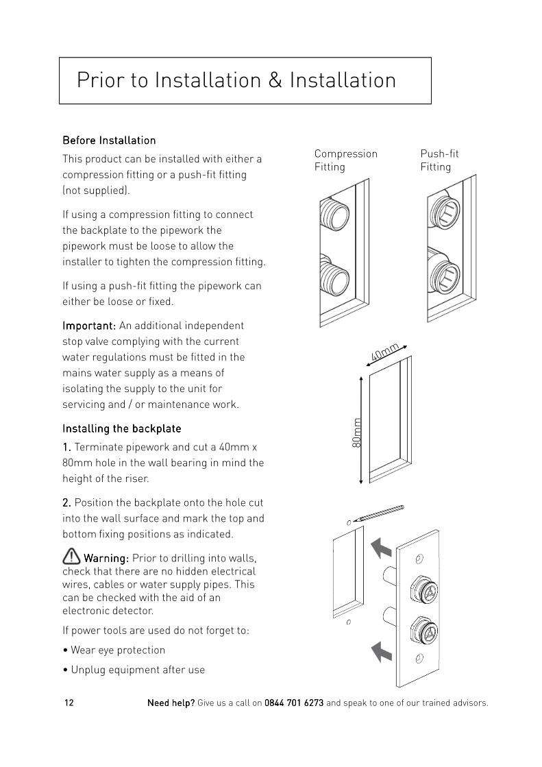
Before InstallationBefore InstallationBefore InstallationBefore Installation
This product can be installed with either a
compression fitting or a push-fit fitting
(not supplied).
If using a compression fitting to connect
the backplate to the pipework the
pipework must be loose to allow the
installer to tighten the compression fitting.
If using a push-fit fitting the pipework can
either be loose or fixed.
Important: Important: Important: Important: An additional independent
stop valve complying with the current
water regulations must be fitted in the
mains water supply as a means of
isolating the supply to the unit for
Compression Fitting
Push-fit Fitting
isolating the supply to the unit for
servicing and / or maintenance work.
Installing the backplateInstalling the backplateInstalling the backplateInstalling the backplate
1111. . . . Terminate pipework and cut a 40mm x
80mm hole in the wall bearing in mind the
height of the riser.
2. 2. 2. 2. Position the backplate onto the hole cut
into the wall surface and mark the top and
bottom fixing positions as indicated.
Warning: Warning: Warning: Warning: Prior to drilling into walls, check that there are no hidden electrical wires, cables or water supply pipes. This can be checked with the aid of an electronic detector.
If power tools are used do not forget to:
• Wear eye protection
• Unplug equipment after use
12 Need help? Need help? Need help? Need help? Give us a call on 0844 701 6273 0844 701 6273 0844 701 6273 0844 701 6273 and speak to one of our trained advisors.
80m
m

Installation cont.
3333. . . . Drill suitable holes at the marked
positions.
4. With Rear Access to the Cavity Hole4. With Rear Access to the Cavity Hole4. With Rear Access to the Cavity Hole4. With Rear Access to the Cavity Hole
The backplate can be secured to the wall
before connecting either the push-fit or
compression fitting connections to the
rear of the backplate.
With No Rear Access to the Cavity HoleWith No Rear Access to the Cavity HoleWith No Rear Access to the Cavity HoleWith No Rear Access to the Cavity Hole
The pipework mustmustmustmust be able to pull through
the hole in the wall cavity sufficiently
enough to enable either the push-fit or
compression fittings to be secured to the
brass connections on the rear of the
Push-fit Fitting
backplate.
Important: Important: Important: Important: The brass connections on the
rear of the backplate must be pushed fully
into the push-fit connections and if
compression fittings are used these must
be securely tightened.
The assembled backplate needs to be able
to push back into the cavity before fixing
the backplate to the wall.
5555. . . . Secure the backplate to the wall using
the fixings supplied.
13Need help? Need help? Need help? Need help? Give us a call on 0844 701 6273 0844 701 6273 0844 701 6273 0844 701 6273 and speak to one of our trained advisors.
Compression Fitting
Installation cont.
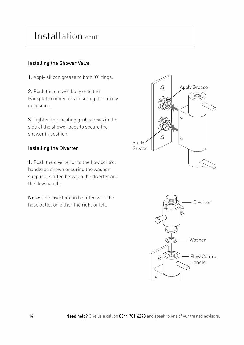
Installing the Shower ValveInstalling the Shower ValveInstalling the Shower ValveInstalling the Shower Valve
1. 1. 1. 1. Apply silicon grease to both ‘O’ rings.
2. 2. 2. 2. Push the shower body onto the
Backplate connectors ensuring it is firmly
in position.
3. 3. 3. 3. Tighten the locating grub screws in the
side of the shower body to secure the
shower in position.
Installing the DiverterInstalling the DiverterInstalling the DiverterInstalling the Diverter
1. 1. 1. 1. Push the diverter onto the flow control
handle as shown ensuring the washer
Apply Grease
Apply Grease
14 Need help? Need help? Need help? Need help? Give us a call on 0844 701 6273 0844 701 6273 0844 701 6273 0844 701 6273 and speak to one of our trained advisors.
supplied is fitted between the diverter and
the flow handle.
Note: Note: Note: Note: The diverter can be fitted with the
hose outlet on either the right or left. Diverter
Washer
Flow Control Handle

Installation cont.
Installing the RiserInstalling the RiserInstalling the RiserInstalling the Riser
1. 1. 1. 1. Screw the riser brackets onto the riser.
2. 2. 2. 2. Push the riser down onto the top of the
diverter valve and position the riser onto
the wall and mark the fixing positions of
the riser brackets.
3. 3. 3. 3. Remove the complete riser from the
shower valve and drill suitable holes for
the bracket fixings.
Warning: Warning: Warning: Warning: Prior to drilling into walls,
check that there are no hidden electrical
wires, cables or water supply pipes. This
can be checked with the aid of an
electronic detector.
If power tools are used do not forget to:
• Wear eye protection
• Unplug equipment after use
4. 4. 4. 4. Screw the inner flexi nut of the riser
onto the thread of the diverter valve
ensuring the sealing washer is fitted
between. Insert the locating pin into the
cut out in the diverter valve and push the
riser down onto the diverter valve.
Pin
Sealing Washer
Nut
Diverter Valve
15Need help? Need help? Need help? Need help? Give us a call on 0844 701 6273 0844 701 6273 0844 701 6273 0844 701 6273 and speak to one of our trained advisors.

Installation cont.
Installing the RiserInstalling the RiserInstalling the RiserInstalling the Riser
5. 5. 5. 5. Secure the riser in position using the fixings provided.
6. 6. 6. 6. Screw the shower rose onto the thread of the rigid riser.
6. 6. 6. 6. Secure the wall bracket to the wall in the desired location using the fixings supplied. Place the handset into the wall bracket.
Warning: Warning: Warning: Warning: Prior to drilling into walls, check that there are no hidden electrical wires, cables or water supply pipes. This can be checked with the aid of an electronic detector.
If power tools are used do not forget to:If power tools are used do not forget to:
• Wear eye protection
• Unplug equipment after use
7. 7. 7. 7. Attach the shower hose to the diverter valve and handset ensuring the sealing washers are fitted.
16 Need help? Need help? Need help? Need help? Give us a call on 0844 701 6273 0844 701 6273 0844 701 6273 0844 701 6273 and speak to one of our trained advisors.

Operation & Temperature Setting
On/Off and Temperature ControlOn/Off and Temperature ControlOn/Off and Temperature ControlOn/Off and Temperature Control
Turn the flow lever to the right to turn on the flow of water. The further the flow lever is turned the greater the flow of water.
To increase the temperature turn the temperature lever fully to the right.
To decrease the temperature turn the temperature lever back towards the off position.
Maximum Temperature SettingMaximum Temperature SettingMaximum Temperature SettingMaximum Temperature Setting
The maximum blend temperature should be limited to ensure that no undesirable temperature is obtained. If adjustment is necessary the following should be carried out:
Flow Lever
Temperature Lever
Diverter Lever
should be carried out:
• Turn the flow lever fully to the right so that the shower is running at full flow.
• Turn the temperature lever fully to the right so that the water is at the maximum temperature (allow the flow/temperature to stabilise for a few minutes).
• Remove the handle by prising out the cap and removing the grub screw.
• Turn the spindle anti-clockwise to increase the temperature and clockwise to decrease the temperature.
• Once the desired temperature has been achieved replace the handle, tighten the grub screw and push the cap back on.
Spindle
Temperature Lever
17Need help? Need help? Need help? Need help? Give us a call on 0844 701 6273 0844 701 6273 0844 701 6273 0844 701 6273 and speak to one of our trained advisors.
Maintenance
General CleaningGeneral CleaningGeneral CleaningGeneral Cleaning
Your fitting has a high quality finish and should be treated with care to preserve the visible surfaces. All finishes will wear if not cleaned correctly. The only safe way to clean your product is to wipe with a soft damp cloth. Stains can be removed using washing up liquid. All bathroom cleaning products (powders and liquids) will damage the surface of your fitting, even the non-scratch cleaners.
Note:Note:Note:Note: Never use abrasive detergents or disinfectants or those containing alcohol, hydrochloric acid or phosphoric acid.
Should the valve require servicing the following procedure should be followed.
• Isolate both hot and cold supplies to the shower valve by either:
• Turning the water supply off at the mains stop cock or
• Turning off the isolation valves to the shower valve.
• Prise out the cap from the temperature handle. Loosen the grub screw and pull the handle off.
• Unscrew the cartridge anti-clockwise using a suitable spanner and remove it from the valve body.
• Soak the cartridge in a 50/50 solution of
Bristan recommend E-cloth for cleaning all of our bathroom & kitchen products. Using just water, E-cloth gives a
smear free, deep clean by breaking up and hold dirt, which normal cloths leave behind. Order through your Bristan stockist (order code: ECLOTH).
ServicingServicingServicingServicing
If your thermostatic mixer valve fails to operate correctly it could be the result of an incorrect installation. Please refer to the installation section & site requirements.
If the valve has operated correctly for some time, but no longer performs acceptably, you may find it useful to firstly refer to the fault diagnosis in the Troubleshooting section.
• Soak the cartridge in a 50/50 solution of hot water and white vinegar and allow to soak for a couple of hours, If heavily scaled allow to soak overnight.
• Grease all seals (light smear only). Only use a silicone based grease on all ‘O’ rings and seals.
• Replace the cartridge and tighten fully using a suitable spanner. Replace the handle, tighten the grub screw and push-fit the cap back into position.
• If the valve still fails it maybe necessary to replace the thermostatic cartridge.
Please visit: www.bristan.com/sparesfinder in order to find spare parts for this product.
18 Need help? Need help? Need help? Need help? Give us a call on 0844 701 6273 0844 701 6273 0844 701 6273 0844 701 6273 and speak to one of our trained advisors.

Hard Water Regions in the UK
Soft to Soft to Soft to Soft to moderately softmoderately softmoderately softmoderately soft0 - 100mg/l as calcium carbonate equivalent
Slightly hard to Slightly hard to Slightly hard to Slightly hard to moderately hardmoderately hardmoderately hardmoderately hard100 - 200mg/l as calcium carbonate equivalent
Hard to very hardHard to very hardHard to very hardHard to very hardAbove 200mg/l as calcium carbonate equivalent
19Need help? Need help? Need help? Need help? Give us a call on 0844 701 6273 0844 701 6273 0844 701 6273 0844 701 6273 and speak to one of our trained advisors.
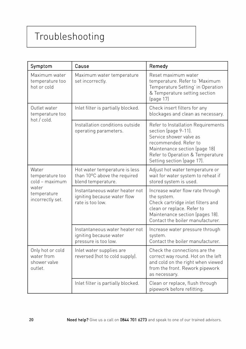
Troubleshooting
SymptomSymptomSymptomSymptom CauseCauseCauseCause RemedyRemedyRemedyRemedy
Maximum water temperature too hot or cold
Maximum water temperature set incorrectly.
Reset maximum watertemperature. Refer to ‘Maximum Temperature Setting’ in Operation & Temperature setting section (page 17)
Outlet water temperature too hot / cold.
Inlet filter is partially blocked. Check insert filters for any blockages and clean as necessary.
Installation conditions outside operating parameters.
Refer to Installation Requirements section (page 9-11).Service shower valve as recommended. Refer to Maintenance section (page 18)Refer to Operation & Temperature Setting section (page 17).
Water temperature too
Hot water temperature is less than 10ºC above the required
Adjust hot water temperature or wait for water system to reheat if temperature too
cold – maximum water temperature incorrectly set.
than 10ºC above the required blend temperature.
wait for water system to reheat if stored system is used.
Instantaneous water heater not igniting because water flow rate is too low.
Increase water flow rate through the system.Check cartridge inlet filters and clean or replace. Refer to Maintenance section (pages 18).Contact the boiler manufacturer.
Instantaneous water heater not igniting because water pressure is too low.
Increase water pressure through system.Contact the boiler manufacturer.
Only hot or cold water from shower valve outlet.
Inlet water supplies are reversed (hot to cold supply).
Check the connections are the correct way round. Hot on the left and cold on the right when viewed from the front. Rework pipework as necessary.
Inlet filter is partially blocked. Clean or replace, flush through pipework before refitting.
20 Need help? Need help? Need help? Need help? Give us a call on 0844 701 6273 0844 701 6273 0844 701 6273 0844 701 6273 and speak to one of our trained advisors.

Troubleshooting
SymptomSymptomSymptomSymptom CauseCauseCauseCause RemedyRemedyRemedyRemedy
No flow when shower is turned on.
Inlet filter is partially blocked. Check insert filters for any blockages and clean as necessary.
Blocked or damaged check valve.
Remove check valve and clean / replace if necessary.
Air block in either / both supplies
Flush through supply pipework.
Piston sticking Remove thermostatic cartridge and piston. Service shower valve. Refer to Maintenance section (page 18).
Pulsating flow and / or varying temperature.
Air block in either / both supplies
Flush through supply pipework.
Incorrect use of flow regulators Check and remove / replace if necessary.necessary.
Flow rate too great
Flow regulators not fitted. Fit flow regulators.
Shower valve will not shut off.
Thermostatic cartridge not shutting off fully.
Service shower valve. Refer to Maintenance section (page 18)
21Need help? Need help? Need help? Need help? Give us a call on 0844 701 6273 0844 701 6273 0844 701 6273 0844 701 6273 and speak to one of our trained advisors.
Guarantee
Bristan offers solid guarantees to provide you with complete peace of mind.
Taps and MixersTaps and MixersTaps and MixersTaps and Mixers5 year parts and 1 year labour*. Gold, painted and special finishes 3 years parts only.
All subject to proof of purchase.
Mixer Shower ValvesMixer Shower ValvesMixer Shower ValvesMixer Shower Valves5 year parts. 1 year labour* (subject to registration), or 1 year with proof of purchase.
Gold, painted and special finishes 3 years parts only.
Pumps and Power Showers Pumps and Power Showers Pumps and Power Showers Pumps and Power Showers 2 year parts. 1 year labour* (subject to registration).
Electric Showers/Instantaneous Water Electric Showers/Instantaneous Water Electric Showers/Instantaneous Water Electric Showers/Instantaneous Water HeatersHeatersHeatersHeaters
*Labour provided by an approved Bristan engineer. Guarantee only applies to products with a manufacturing fault. A deferred payment will be necessary in order to secure any visits by our engineers which will be charged if the problem is found notnotnotnot to be a manufacturing fault. If the fault is found to be down to a manufacturing error, the payment will be released and not charged.
This guarantee applies to products purchased within the United Kingdom or Republic of Ireland, but does not apply to products used commercially.
The guarantee is only available to original purchasers who have proof of purchase.
The installation must allow ready access to all products for the purpose of inspection, maintenance or replacement.
Any part found to be defective during the above HeatersHeatersHeatersHeaters2 year parts. 1 year labour* (subject to registration).
AccessoriesAccessoriesAccessoriesAccessories5 year parts only. Includes bathrooms accessories, shower accessories (e.g. hoses, handsets and poles), wastes, WC levers and light pulls. Gold, painted and special finishes 3 years parts only.
SanitarywareSanitarywareSanitarywareSanitaryware5 year parts only. Subject to proof of purchase.
Shower Enclosures and Shower Trays Shower Enclosures and Shower Trays Shower Enclosures and Shower Trays Shower Enclosures and Shower Trays 10 year parts (subject to registration), or 2 years with proof of purchase. 1 year labour* (subject to registration), or 1 year with proof of purchase.
Heated Towel RailsHeated Towel RailsHeated Towel RailsHeated Towel Rails5 year parts only. Gold, painted and special finishes 3 years parts only. All subject to proof of purchase.
Any part found to be defective during the above guarantee period will be replaced without charge, providing that the product has been installed in accordance with the instructions, used as intended, and regularly serviced.
Servicing should be carried out at regular intervals of no more than 12 months and more frequently in hard water areas (heavy lime scale) areas.
In the unlikely event that any problems are encountered with the product’s performance on installation, you must obtain guidance/authorisation from our Customer Service Department, and be able to supply proof and date of purchase, before any remedial action is taken.
The guarantee excludes general wear and tear and damage caused by accident, misuse or neglect, and does not cover the following:
22 Need help? Need help? Need help? Need help? Give us a call on 0844 701 6273 0844 701 6273 0844 701 6273 0844 701 6273 and speak to one of our trained advisors.
Guarantee cont.
• Components that are subject to general wear and tear such as filters, seals, ‘O’ rings and washers etc.
• Damage caused by faulty installation
• Damage caused by lime scale or any waterborne debris
• Damage caused by inappropriate cleaning products (see cleaning section)
• Damage caused by the use of non-Bristan parts
•The product being used for a purpose other than intended by the manufacturer.
In the interests of continuous product improvement Bristan reserves the right to alter specification as necessary.
Replacement Parts PolicyReplacement Parts PolicyReplacement Parts PolicyReplacement Parts Policy
Important:Important:Important:Important:
In the event of product or component malfunction, DO NOT tamper with or remove the product from site. Telephone the Customer Services Department and be prepared with the date of purchase, model number and a clear description of the complaint.purchase, model number and a clear description of the complaint.
Our service staff are fully qualified to advise on correct installation procedures and will be able to diagnose whether the fault will require a replacement part or a visit from a Bristan engineer.
If required, a service call will be booked and either yourself or an appointed representative (who should be a person of 18 years or over) must be present during the visit.
All site visits to products out of guarantee will be carried out free of any parts or labour charges provided the conditions of the guarantee have been adhered to (the 2nd to 5th year of the guarantee is parts only, unless registered).
All site visits to products out of guarantee will be subject to charges for parts and labour. Charges will also be levied on cancelled appointments, unless advised to Bristan at least 24 hours in advance of the agreed date and time.
Should a product be discontinued, Spare parts stocks will be maintained, but in the event of a part becoming unavailable Bristan reserve the right to supply a substitute of equal quality.
In order to log an enquiry with us please visit http://www.bristan.com/customerservice
Opening times: Please refer to the Bristan website.
Customer Service: Tel: 0844 701 6273 • Fax: 0844 701 6275Tel: 0844 701 6273 • Fax: 0844 701 6275Tel: 0844 701 6273 • Fax: 0844 701 6275Tel: 0844 701 6273 • Fax: 0844 701 6275
23Need help? Need help? Need help? Need help? Give us a call on 0844 701 6273 0844 701 6273 0844 701 6273 0844 701 6273 and speak to one of our trained advisors.

Part Number: PM VSHXSPDIV C / B
Issue: D1
Bristan Group Ltd.
Birch Coppice Business Park
Dordon
Tamworth
Staffordshire
B78 1SG
Web: www.bristan.com
Email: [email protected]
A Masco Company