installation instructions - myrheem.compts.myrheem.com/.../pdfs/furnaces/io/92-23531-16-09.pdf ·...
TRANSCRIPT

!
If the information in these instructions is not followed exactly, afire or explosion may result, causing property damage, personalinjury or death.
INSTALLATION INSTRUCTIONSFOR UPFLOW & DOWNFLOW/HORIZONTAL HIGHEFFICIENCY CONDENSING GAS FURNACESRGRA/RGRJ AND RGTA/RGTJ SERIES
92-23531-16-09SUPERSEDES 92-23531-16-08
THESE INSTRUCTIONS AREINTENDED AS AN AID TOQUALIFIED SERVICEPERSONNEL FOR PROPERINSTALLATION, ADJUSTMENTAND OPERATION OF THISUNIT. READ THESEINSTRUCTIONS THOROUGHLYBEFORE ATTEMPTINGINSTALLATION OROPERATION. FAILURE TOFOLLOW THESEINSTRUCTIONS MAY RESULTIN IMPROPER INSTALLATION,ADJUSTMENT, SERVICE ORMAINTENANCE, POSSIBLYRESULTING IN FIRE,ELECTRICAL SHOCK, CARBONMONOXIDE POISONING,EXPLOSION, PROPERTYDAMAGE, PERSONAL INJURYOR DEATH.
Do Not Destroy this Manual.Please read carefully and keepin a safe place for futurereference by a serviceman.
WARNING
Recognize this symbol as an indication of Important Safety Information!!
— Do not store or use gasoline or otherflammable vapors and liquids, or othercombustible materials in the vicinity of thisor any other appliance.
— WHAT TO DO IF YOU SMELL GAS• Do not try to light any appliance.• Do not touch any electrical switch; do not
use any phone in your building.• Immediately call your gas supplier from a
neighbor’s phone. Follow the gassupplier’s instructions.
• If you cannot reach your gas supplier,call the fire department.
• Do not return to your home untilauthorized by the gas supplier or firedepartment.
— DO NOT RELY ON SMELL ALONE TODETECT LEAKS. DUE TO VARIOUSFACTORS, YOU MAY NOT BE ABLE TOSMELL FUEL GASES.• U.L. recognized fuel gas and CO
detectors are recommended in allapplications, and their installation shouldbe in accordance with the manufacturer’srecommendations and/or local laws,rules, regulations, or customs
— Improper installation, adjustment, alteration,service or maintenance can cause injury,property damage or death. Refer to thismanual. Installation and service must beperformed by a qualified installer, serviceagency or the gas supplier.
WARNING!
PROPOSITION 65: THIS FURNACE CONTAINS FIBERGLASSINSULATION. RESPIRABLE PARTICLES OF FIBERGLASS AREKNOWN TO THE STATE OF CALIFORNIA TO CAUSE CANCER.EXHAUST GAS FROM THIS FURNACE CONTAINS CHEMICALS,INCLUDING CARBON MONOXIDE, KNOWN TO THE STATE OFCALIFORNIA TO CAUSE BIRTH DEFECTS OR OTHERREPRODUCTIVE HARM.
WARNING!
FOR YOUR SAFETY!
INSTALLATION CHECK LISTREFER TO INSTALLATION INSTRUCTIONS
GAS SUPPLY
Adequate pipe size
Correct supply pressure (during furnace operation)
Manifold pressure
No gas leaks
ELECTRICAL
115 V.A.C. supply (Single Circuit)
Polarity observed
Furnace properly grounded
Adequate wire size
FURNACE INSTALLATION
Adequate clearance to combustibles
Adequate clearance for service (at front)
DUCT STATIC PRESSURE
in. w.c. on heating speed
in. w.c. on cooling speed
Air temperature rise
CONDENSATE LINE
Trap filled with water
Vented
Sloped toward drain
Condensate drain line hoses connectedand clamped
Freeze protection (if necessary)
VENTING – DIRECT VENT
in. diameter – intake pipe
in. diameter – exhaust pipe
ft. of pipe – intake air
no. of elbows – intake air
ft. of pipe – exhaust pipe
no. of elbows – exhaust pipe
TERMINATIONS – DIRECT VENT
VERTICAL
Intake – 12" min. above roof/snow level
Correct relationship – exhaust to intake
VERTICAL – CONCENTRIC (RXGY-E02)
Intake – 12" min. above roof/snow level
HORIZONTAL – STANDARD (RXGY-D02, -D03)
Correct relationship – exhaust to intake
12" min. above grade/snow level
HORIZONTAL – ALTERNATE (RXGY-D02, -D03 OR -D04)
Correct relationship – exhaust to intake
Above anticipated snow level
HORIZONTAL – CONCENTRIC (RXGY-C01)
12" min. above grade/snow level
Intake “Y” rotated above center
Exhaust sloped toward furnace
VENTING – NON-DIRECT VENT
in. diameter – exhaust pipe
ft. of pipe – exhaust
no. of elbows
TERMINATION – NON-DIRECT VENT
VERTICAL
12" min. above roof/snow level
HORIZONTAL – STANDARD
12" min. above grade/snow level
HORIZONTAL – ALTERNATE
Above anticipated snow level
2
3
IMPORTANT: TO INSURE PROPER INSTALLATION AND OPERATION OFTHIS PRODUCT, COMPLETELY READ ALL INSTRUCTIONS PRIOR TOATTEMPTING TO ASSEMBLE, INSTALL, OPERATE, MAINTAIN OR REPAIRTHIS PRODUCT. UPON UNPACKING OF THE FURNACE, INSPECT ALLPARTS FOR DAMAGE PRIOR TO INSTALLATION AND START-UP.
CONTENTS
Safety Precautions ...................................................................................................1
Installation Check List ..............................................................................................2
Location Requirements and Considerations ............................................................5
Venting and Combustion Air Piping .......................................................................12
Combustion and Ventilation Air..............................................................................14
Vent Pipe Installation..............................................................................................17
Condensate Drain/Neutralizer................................................................................27
Converting Downflow to Horizontal ........................................................................29
Gas Supply and Piping...........................................................................................31
Electrical Wiring......................................................................................................35
Accessories ............................................................................................................37
Start-Up Procedures...............................................................................................44
Air Flow...................................................................................................................46
Maintenance...........................................................................................................50
Troubleshooting......................................................................................................53
Wiring Diagrams.....................................................................................................59
➤ Installation Instructions are updated on a regular basis. This is done asproduct changes occur or if new information becomes available. In thispublication, an arrow (➤) denotes changes from the previous edition or additionalnew material.

GENERAL INFORMATIONThe RGRA/RGRJ and RGTA/RGTJseries furnaces are design-certifiedby AGA/CGA for use with natural andpropane gases as follows:
1. As non-direct vent central forcedair furnaces taking combustionair from the installation area orusing air ducted from the outside.
2. As direct vent central forced airfurnaces with all combustion airsupplied directly to the furnaceburners through a special airintake system outlined in theseinstructions.
4
FIGURE 1UPFLOW FURNACE
FIGURE 2DOWNFLOW/HORIZONTAL FURNACE
Install this furnace in accordance withthe American National StandardZ223.1 – latest edition entitled“National Fuel Gas Code” (NFPA54)and requirements or codes of thelocal utilities or other authoritieshaving jurisdiction. This is availablefrom the following:
National Fire ProtectionAssociation, Inc.
Batterymarch ParkQuincy, MA 02269
American Gas Association1515 Wilson Blvd.Arlington, VA 22209
Install units in Canada in accordancewith CAN/CGA-B149, localinstallation codes and authoritieshaving jurisdiction. CAN/CGA-B149 isavailable from:
Canadian Gas Association55 Scarsdale RoadDon Mills, Ontario, Canada M3B, 2R3
2425262728
ITEM ITEMNO. PART NAME NO. PART NAME
1 INDUCED DRAFT BLOWER 15 LOW VOLTAGE TERMINAL2 CAPACITOR 16 TRANSFORMER3 INLET AIR CHASE 17 PRESSURE SWITCH4 DOOR SWITCH 18 OUTLET AIR PIPE5 JUNCTION BOX 19 GAS VALVE6 INLET PIPE CONNECTOR 20 CONNECTOR7 TOP PLATE 21 EXHAUST TRANSITION8 ELECTRICAL BOX 22 CONDENSATE TRAP9 AUXILLIARY LIMIT 23 IGNITER10 CONTROL BOX COVER GROUND 24 MANIFOLD11 VENT CAP PLUG 25 OVERTEMPERATURE SWITCH12 EXHAUST CONNECTION 26 ROLLOUT SWITCH13 BLOWER 27 SENSOR14 EXHAUST PIPE EXTENSION 28 BURNER
ITEM ITEMNO. PART NAME NO. PART NAME
1 CONDENSATE TRAP 13 TOP PLATE2 DOOR SWITCH 14 BURNER3 JUNCTION BOX 15 IGNITER4 TRANSFORMER 16 COMBUSTION AIR INLET5 BLOCKED DRAIN PRESSURE SWITCH 17 GAS VALVE6 MAIN PRESSURE SWITCH 18 INDUCED DRAFT BLOWER7 EXHAUST TRANSITION 19 LOW VOLTAGE TERMINAL8 CONNECTOR 20 CAPACITOR9 OUTLET AIR PIPE 21 ELECTRICAL BOX10 VENT CAP PLUG 22 BLOWER11 SENSOR 23 CONTROL BOX12 OVERTEMPERATURE SWITCH COVER GROUND
1
2
3
4
5
6
7 8 9 10
11
12
13
14
15
16
17
18
19
20
21
22
23
1
2
3
4
5
6
7
8
9
10 11 12 13 14 15 16
17
18
19
20
21
2223
GAS INLET
OPTIONALCOMBUSTIONAIR INLET
I409 I409
GASINLET
PVC
PVC
GENERAL INFORMATION1. IMPORTANT: If furnace
operation is required duringconstruction, and air ladenedwith corrosive compounds suchas chlorine and fluorine arepresent, provisions must betaken to provide clean outdoorcombustion and ventilation air tothe furnace. Compounds ofchlorine and fluorine, whenburned with combustion air, formacids which will cause corrosionof a heat exchanger. Some ofthese compounds are found inpaneling, dry wall, tile adhesives,paints, stains and varnishes,solvents and masonry curing andcleaning materials.
DO NOT INSTALL THIS FURNACEIN A MOBILE HOME!! This furnaceis not approved for installation in amobile home. Doing so could causeFIRE, PROPERTY DAMAGE,PERSONAL INJURY OR DEATH.
WHEN THIS FURNACE ISINSTALLED IN A RESIDENTIALGARAGE, IT MUST BE INSTALLEDSO THE BURNERS AND IGNITIONSOURCE ARE LOCATED NO LESSTHAN 18 INCHES ABOVE THEFLOOR. THIS IS TO PREVENTTHE RISK OF IGNITING FLAM-MABLE VAPORS WHICH MAYBE PRESENT IN A GARAGE.ALSO, THE FURNACE MUST BELOCATED OR PROTECTED TOAVOID PHYSICAL DAMAGE BYVEHICLES. FAILURE TO FOLLOWTHESE WARNINGS CAN CAUSE AFIRE OR EXPLOSION, RESULTINGIN PROPERTY DAMAGE,PERSONAL INJURY OR DEATH.
5
2. IMPORTANT: If installing theunit over a finished ceiling orliving area, be certain to installan auxiliary condensate drainpan under the entire unit. Thisauxiliary drain pan should extendunder any evaporator coilinstalled with the furnace.
3. IMPORTANT: If using a coolingevaporator coil with thisfurnace:
a. be sure the air passes overthe heat exchanger beforepassing over the coolingcoil. The cooled air passingover the warm ambient airinside the heat exchangertubes can causecondensation inside the tubesresulting in corrosion andeventual failure.
b. install a parallel duct systemto divert all the air from thefurnace allowing it to passover the cooling coil only. Usedampers or other means toprevent chilled air frompassing over the heatexchanger.
If these are manual dampers, theymust be equipped to prevent heatingor cooling operation unless thedamper is in the full heat or coolposition.
! WARNING
! WARNING
4. IMPORTANT: Install thefurnace level. If it is not level,condensate cannot drainproperly, possibly causingfurnace shut down.
NOTE: These furnaces are approvedfor installation in attics, as well asalcoves, utility rooms, closets andcrawlspaces. Provisions must bemade to prevent freezing ofcondensate.
5. IMPORTANT: If this furnace isinstalled in a garage, atticand/or any unconditionedspace, install a self-regulatingheat tape around thecondensate trap and along theentire length of the condensatedrain in the unconditionedspace. See Figure 3.
When the condensing horizontalgas furnace is installed in anunconditioned space where thetemperature would be capable ofreaching close to or below 32°F(0°C). A SELF-REGULATINGHEAT TAPE IS REQUIRED ONTHE CONDENSATE DRAIN,ALONG WITH AN INSULATIONWRAP. The heat tape shouldmeet the following requirements:
LOCATION REQUIREMENTS AND CONSIDERATIONS
FIGURE 3HORIZONTAL FURNACE W/HEAT TAPE ON CONDENSATE TRAP
DRAINPIPE
HEATTAPE
TRAP
I526
6
a. The heat tape must be ULlisted.
b. The heat tape must beinstalled per themanufacturer’s instructions forthe entire length of drain pipein the unconditioned space.
c. The heat tape should be ratedat 5 or 6 watts per foot at120V.
IMPORTANT: Support this unitwhen installed. Since thisfurnace is suitable for attic orcrawl space installation, it maybe installed on combustible woodflooring or by using supportbrackets. See Figure 4.
6. IMPORTANT: If installing in autility room, be sure the dooris wide enough to:
a. allow the largest part of thefurnace to pass; or
b. allow any other appliance(such as a water heater)to pass.
7. IMPORTANT: This furnace isnot approved or recommendedfor installation on its back,with access doors facingupwards.
CLEARANCE -ACCESSIBILITYThe design of forced air furnaces withinput ratings as listed in the tablesunder Figures 6, 7 and 8 are certifiedby the AGA Laboratories and CGALaboratories for the clearances tocombustible materials shown ininches.
FIGURE 4HORIZONTAL FURNACE INSTALLED W/SUPPORT BRACKETS
GASPIPE
TRAP
EXHAUSTFAN
ELECTRICALCONDUIT
INTAKEVENT
See name/rating plate and clearancelabel for specific model number andclearance information.
Service clearance of at least 24inches is recommended in front ofall furnaces.
FOR PURPOSES OF SERVICINGTHIS APPLIANCE, ACCESSIBILITYCLEARANCES, WHERE GREATER,MUST TAKE PRECEDENCE OVERFIRE PROTECTION CLEARANCES.
UPFLOW AND HORIZONTALFURNACES ARE DESIGN-CERTIFIED FOR INSTALLATIONON COMBUSTIBLE FLOORS.NOTE, HOWEVER, THAT FUR-NACES MUST NOT BE INSTALLEDDIRECTLY ON CARPETING, TILEOR OTHER COMBUSTIBLEMATERIAL OTHER THAN WOODFLOORING. INSTALLATION ON ACOMBUSTIBLE MATERIAL CANRESULT IN FIRE, CAUSINGPROPERTY DAMAGE, PERSONALINJURY OR DEATH.
Upflow furnaces are shipped with abottom closure panel installed. Whenbottom return air is used, remove thepanel by removing the two screwsattaching the panel to the front baseangle. See Figure 5.
! WARNING
I522

7
SITE SELECTION1. Select a site in the building near
the center of the proposed, orexisting, duct system.
2. Give consideration to the ventsystem piping when selecting thefurnace location. Be sure theventing system can get from thefurnace to the termination withminimal length and elbows.
3. Locate the furnace near theexisting gas piping. Or, if runninga new gas line, locate thefurnace to minimize the lengthand elbows in the gas piping.
4. Locate the furnace to maintainproper clearance to combustiblesas shown in the following tables.
! WARNINGCOMBUSTIBLE MATERIAL MUSTNOT BE PLACED ON OR AGAINSTTHE FURNACE JACKET. THEAREA AROUND THE FURNACEMUST BE KEPT CLEAR AND FREEOF ALL COMBUSTIBLEMATERIALS INCLUDING GASO-LINE AND OTHER FLAMMABLEVAPORS AND LIQUIDS.PLACEMENT OF COMBUSTIBLEMATERIALS ON, AGAINST ORAROUND THE FURNACE JACKETCAN CAUSE AN EXPLOSION ORFIRE RESULTING IN PROPERTYDAMAGE, PERSONAL INJURY ORDEATH. THE HOMEOWNERSHOULD BE CAUTIONED THATTHE FURNACE AREA MUST NOTBE USED AS A BROOM CLOSETOR FOR ANY OTHER STORAGEPURPOSES.
FIGURE 5BOTTOM PANEL REMOVAL
JACKET ASSEMBLY
SOLID BOTTOM
NOTE:BACK FLANGE OF SOLID BOTTOM FITSUNDERNEATH JACKET. SIDES AND FRONTFLANGES FIT OVER FLANGES ON JACKET.SCREW
(2) REQ’D.
JACKET ASSEMBLY
FILTER FILTERROD
SOLID BOTTOM REMOVAL
FILTER & ROD LOCATION
ADS 5422-01
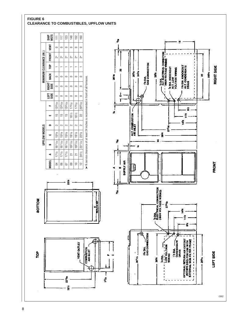
FIGURE 6CLEARANCE TO COMBUSTIBLES, UPFLOW UNITS
8
UPFL
OW M
ODEL
SM
INIM
UM C
LEAR
ANCE
(IN.
)
LEFT
RIGH
TSH
IPM
ODEL
AB
CD
EF
SIDE
SIDE
BACK
TOP
FRON
TVE
NTW
GTS
0417
1 /2
1611
/32
155 /
82
1513
25/3
20
00
12*
011
1
0617
1 /2
1611
/32
155 /
82
1513
25/3
20
00
12*
011
7
0717
1 /2
1611
/32
155 /
82
1513
25/3
20
00
12*
012
3
0921
1927
/32
191 /
82
181 /
217
9 /32
00
01
2*0
148
1021
1927
/32
191 /
82
181 /
217
9 /32
00
01
2*0
152
1224
1 /2
2311
/32
225 /
82
2220
25/3
20
00
12*
016
0
I392
➤*A
ser
vice
cle
aran
ce o
f at l
east
24
inch
es is
reco
mm
ende
d in
fron
t of a
ll fu
rnac
es.
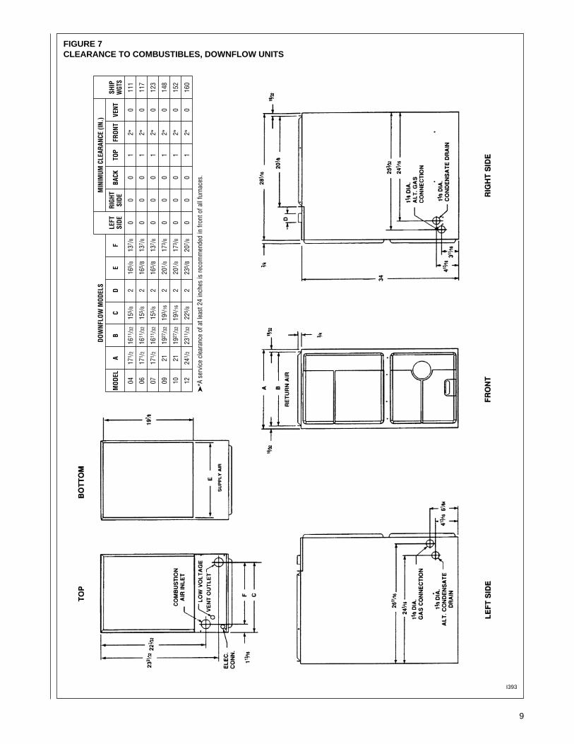
FIGURE 7CLEARANCE TO COMBUSTIBLES, DOWNFLOW UNITS
9
DOW
NFLO
W M
ODEL
SM
INIM
UM C
LEAR
ANCE
(IN.
)
LEFT
RIGH
TSH
IPM
ODEL
AB
CD
EF
SIDE
SIDE
BACK
TOP
FRON
TVE
NTW
GTS
0417
1 /2
1611
/32
155 /
82
165 /
813
7 /8
00
01
2*0
111
0617
1 /2
1611
/32
155 /
82
165 /
813
7 /8
00
01
2*0
117
0717
1 /2
1611
/ 32
155 /
82
165 /
813
7 /8
00
01
2*0
123
0921
1927
/ 32
193 /
162
201 /
817
3 /8
00
01
2*0
148
1021
1927
/ 32
193 /
162
201 /
817
3 /8
00
01
2*0
152
1224
1 /2
2311
/ 32
225 /
82
235 /
820
7 /8
00
01
2*0
160
I393
➤*A
ser
vice
cle
aran
ce o
f at l
east
24
inch
es is
reco
mm
ende
d in
fron
t of a
ll fu
rnac
es.
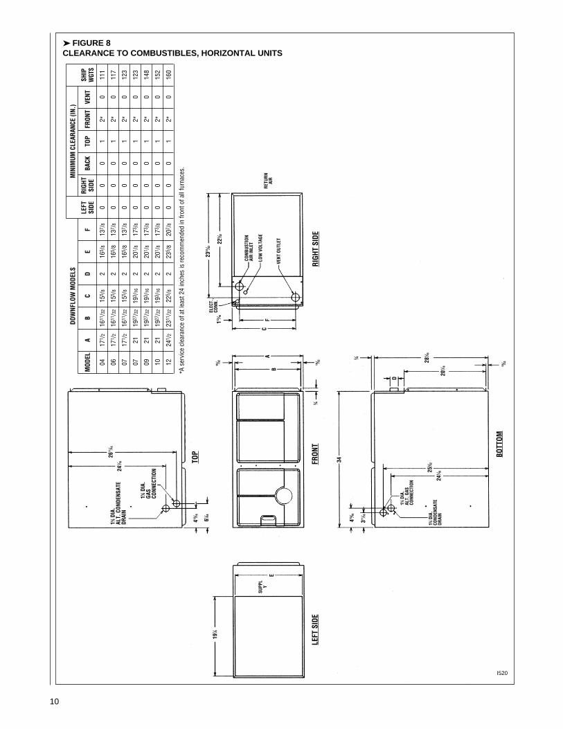
➤ FIGURE 8CLEARANCE TO COMBUSTIBLES, HORIZONTAL UNITS
DOW
NFLO
W M
ODEL
SM
INIM
UM C
LEAR
ANCE
(IN.
)
LEFT
RIGH
TSH
IPM
ODEL
AB
CD
EF
SIDE
SIDE
BACK
TOP
FRON
TVE
NTW
GTS
0417
1 /2
1611
/32
155 /
82
165 /
813
7 /8
00
01
2*0
111
0617
1 /2
1611
/32
155 /
82
165 /
813
7 /8
00
01
2*0
117
0717
1 /2
1611
/32
155 /
82
165 /
813
7 /8
00
01
2*0
123
0721
1927
/32
193 /
162
201 /
817
3 /8
00
01
2*0
123
0921
1927
/32
193 /
162
201 /
817
3 /8
00
01
2*0
148
1021
1927
/32
193 /
162
201 /
817
3 /8
00
01
2*0
152
1224
1 /2
2311
/32
225 /
82
235 /
820
7 /8
00
01
2*0
160
10
I520
*A s
ervi
ce c
lear
ance
of a
t lea
st 2
4 in
ches
is re
com
men
ded
in fr
ont o
f all
furn
aces
.
15 ⁄8DIA
.AL
T. C
ONDE
NSAT
EDR
AIN
15 ⁄8DIA
.GA
SCO
NNEC
TION
TOP
LEFT
SID
EFR
ONT
BOTT
OM
RIGH
T SI
DE
413⁄16
61 ⁄64
241 ⁄16
197 ⁄8
2331⁄32
113⁄16
34
413⁄16
253 ⁄32
D
281 ⁄16
201 ⁄18 19
⁄32
241 ⁄16
3 ⁄4311
⁄16
15 ⁄8DIA
.AL
T. G
ASCO
NNEC
TION
15 ⁄8DIA
.CO
NDEN
SATE
DRAI
N
COM
BUST
ION
AIR
INLE
T
LOW
VOL
TAGE
RETU
RNAI
R
VENT
OUT
LET
223 ⁄32
ELEC
T.CO
NN.
19⁄32
19⁄32
3 ⁄4
EB
AC
FSU
PPL
Y
2611⁄16

11
DUCTINGProper air flow is required for thecorrect operation of this furnace.Too little air flow can cause erraticoperation and can damage the heatexchanger. The duct system mustcarry the correct amount of air forheating and cooling if summer airconditioning is used.
Size the ducts according toacceptable industry standards andmethods. The total static pressuredrop of the air distribution systemshould not exceed 0.5" w.c.
NEVER ALLOW THE PRODUCTSOF COMBUSTION FROM THEFLUE TO ENTER THE RETURN AIRDUCTWORK OR THECIRCULATED AIR SUPPLY. ALLRETURN DUCTWORK MUST BEADEQUATELY SEALED ANDSECURED TO THE FURNACEWITH SHEET METAL SCREWS;AND JOINTS, TAPED. ALL OTHERDUCT JOINTS MUST BE SECUREDWITH APPROVED CONNECTIONSAND SEALED AIRTIGHT. WHEN ANUPFLOW FURNACE IS MOUNTEDON A PLATFORM WITH RETURNTHROUGH THE BOTTOM, IT MUSTBE SEALED AIRTIGHT BETWEENTHE FURNACE AND THE RETURNAIR PLENUM. THE FLOOR ORPLATFORM MUST PROVIDESOUND PHYSICAL SUPPORT OFTHE FURNACE WITHOUTSAGGING, CRACKS, OR GAPS,AROUND THE BASE, PROVIDING ASEAL BETWEEN THE SUPPORTAND THE BASE.
FAILURE TO PREVENTPRODUCTS OF COMBUSTIONFROM BEING CIRCULATED INTOTHE LIVING SPACE CAN CREATEPOTENTIALLY HAZARDOUSCONDITIONS, INCLUDINGCARBON MONOXIDE POISONINGTHAT COULD RESULT INPERSONAL INJURY OR DEATH.
DO NOT, UNDER ANYCIRCUMSTANCES, CONNECTRETURN OR SUPPLY DUCTWORKTO OR FROM ANY OTHER HEATPRODUCING DEVICE SUCH AS AFIREPLACE INSERT, STOVE, ETC.DOING SO MAY RESULT IN FIRE,CARBON MONOXIDE POISONING,EXPLOSION, PERSONAL INJURYOR PROPERTY DAMAGE.
IMPORTANT: Some high efficiencyfilters have a greater than normalresistance to air flow. This canadversely affect furnace operation.BE SURE TO CHECK AIR FLOW ifusing any filter other than the factory-provided filter.
UPFLOW UNITS1. Position the unit to minimize long
runs of duct or runs of duct withmany turns and elbows.
2. Open the return air compartment.
a. If using side or back return air,do not remove the bottombase.
b. Cut an opening in the side orback. The opening should be cut the full width of theknockouts on the unit.
c. Remove the bottom base ifusing bottom return air.
NOTE: Where the maximum air flowis 1800 CFM or more, both sides orthe bottom must be used for returnair.
3. Connect the return duct or returnair cabinet to the unit. Make theconnection air tight to prevententraining combustion gasesfrom an adjacent fuel-burningappliance.
4. Be sure to have adequatespace for the unit filter.
NOTE: DO NOT take return airfrom bathrooms, kitchens,furnace rooms, garages, utility orlaundry rooms, or cold areas.
5. If summer air conditioning isdesired, position the indoor coilon the top of the unit. Insure thatno air can bypass this coil.
6. Connect the supply air plenum tothe furnace plenum opening.
IMPORTANT: If a flexible ductconnector must be used, itMUST be rated for a minimumtemperature of 250°F.continuous.
DOWNFLOW UNITS1. Position the unit to minimize long
runs of duct or runs of duct withmany turns and elbows.
2. If summer air conditioning isdesired, position the indoor coilon the bottom of the unit. Insurethat no air can bypass this coil.
3. If installing on a combustible floorand not using an air condition-ing plenum, install the specialnon-combustible floor base. SeeFigure 9.
THE DOWNFLOW FURNACEDESIGN IS CERTIFIED FORINSTALLATION ON A NON-COMBUSTIBLE FLOOR. USE THESPECIAL BASE SPECIFIED ONTHE FURNACE CLEARANCELABEL. FAILURE TO INSTALL THESPECIAL BASE MAY RESULT INFIRE, PROPERTY DAMAGE,PERSONAL INJURY OR DEATH.THIS SPECIAL BASE IS SHIPPEDFROM THE FACTORY AS ANACCESSORY. 4. Connect the furnace to the
supply air plenum.
5. Connect the return air ducting tothe return air opening at the topof the unit. Make the connectionair tight to prevent entrainingcombustion gases from anadjacent fuel-burning appliance.
6. Be sure to have adequatespace for the unit filter.
NOTE: DO NOT take return airfrom bathrooms, kitchens,furnace rooms, garages, utility orlaundry rooms, or cold areas.
! WARNING! WARNING
FIGURE 9COMBUSTIBLE FLOOR BASE
12
GENERAL INFORMATION
READ AND FOLLOW ALL IN-STRUCTIONS IN THIS SECTION.FAILURE TO PROPERLY VENTTHIS FURNACE CAN CAUSECARBON MONOXIDE POISONINGOR AN EXPLOSION OR FIRE,RESULTING IN PROPERTYDAMAGE, PERSONAL INJURYOR DEATH.
This furnace removes both sensibleand latent heat from the combustionflue gases. Removal of latent heatresults in condensation of flue gaswater vapor. This condensed watervapor drains from the secondary heatexchanger and out of the unit into adrain trap.
When installed as a non-direct ventfurnace, only exhaust piping isrequired and inside combustion airmay be used. Refer to section on“COMBUSTION & VENTILATION AIRFOR FURNACE INSTALLATIONS.”
Direct vent installations require adedicated combustion air and ventingsystem. All air for combustion is takenfrom the outside atmosphere and allcombustion products are dischargedto the outdoors.
The combustion air and vent pipefittings must conform to AmericanNational Standards Institute (ANSI)and American Society for TestingMaterials (ASTM) standardsD1785 (Schedule 40 PVC), D2665(PVC-DWV), D2241 (SDR-21 andSDR26-26 PVC), D2661 (ABS-DWV)or F628 (Schedule 40 ABS-DWV).
In Canada all combustion air and ventpipe must be CSA- or ULC-certifiedSchedule 40 PVC, PVC-DWV orABS-DWV.
IMPORTANT: The plastic combustionair and venting components are ofSchedule 40 PVC. If using ABS
piping, ensure that the solventcement is compatible for joiningPVC to ABS components or use amechanical connection that canwithstand the vent temperatures andare corrosion resistant.
NOTE: Schedule 40 ABS-DWV pipeand fittings may be used as analternate to PVC pipe for thecombustion air inlet and vent pipes.
NOTE: Cellular core PVC is alsoapproved for use. It must be schedule40PVC-DWV cellular pipe for non-pressure applications andmanufactured under ASTM F-891.
OVERTEMPERATURESAFETY SWITCHESFurnaces are equipped with safetyswitches in the control compartmentto protect against overtemperatureconditions caused by inadequatecombustion air supply. The switchesfor the upflow and downflow modelsare located in the burnercompartment. If a switch is tripped itmust be manually reset.
DO NOT JUMPER THESEDEVICES! IF ONE OF THESESWITCHES SHOULD TRIP, AQUALIFIED INSTALLER, SERVICEAGENCY OR THE GAS SUPPLIERMUST BE CALLED TO CHECKAND/OR CORRECT FORADEQUATE COMBUSTION AIRSUPPLY. DO NOT RESET THESWITCHES WITHOUT TAKINGCORRECTIVE ACTION TO ASSURETHAT AN ADEQUATE SUPPLY OFCOMBUSTION AIR IS MAINTAINEDUNDER ALL CONDITIONS OFOPERATION. FAILURE TO DO SOCAN RESULT IN CARBON
MONOXIDE POISONING ORDEATH. IF THIS UNIT IS MOUNTEDIN A CLOSET, THE DOOR MUSTBE CLOSED WHEN MAKING THISCHECK.
REPLACE THESE SWITCHESONLY WITH THE IDENTICALREPLACEMENT PART.
EXISTING VENT SYSTEMSWhen the installation of this furnacereplaces an existing furnace that isremoved from a vent system servingother appliances, the vent system islikely to be too large to properly ventthe remaining attached appliances.The following steps should befollowed with each applianceremaining connected to the originalcommon vent system. Place theappliance to be tested in operation,while the other appliances remainingconnected to the common ventsystem are not in operation. Test theoperation of each applianceindividually by the following method.1. Permanently seal any unused
openings in the common ventingsystem.
2. Visually inspect the ventingsystem for proper size andhorizontal pitch and determinethat there is no blockage,restriction, leakage, corrosion orother deficiencies which couldcause an unsafe condition.
3. If practical, close all buildingdoors, windows and all doorsbetween the space where theappliances remaining connectedto the common venting systemare located.Turn on clothes dryers and anyappliance not connected to thecommon venting system. Turn onany exhaust fans, such as rangehoods and bathroom exhausts,so they will operate at maximumspeed. Do not operate a summerexhaust fan. Close fireplacedampers.
VENTING AND COMBUSTION AIR PIPING
! WARNING
! WARNING
HORIZONTAL UNITIMPORTANT: THIS FURNACE MAYONLY BE INSTALLED SO ASWHEN FACING THE FRONT OFTHE FURNACE, SUPPLY AIR ISDISCHARGED ON THE LEFT HANDSIDE.
1. Position the unit to minimize longruns or runs with many turns andelbows.
2. If summer air conditioning isdesired, position the indoor coilon the left end of the unit. Insurethat no air can bypass this coil.
3. Connect the furnace to thesupply air plenum.
4. Connect the return air ducting tothe return air opening at the rightend of the unit. Make theconnection air tight to prevent
entraining combustion gasesfrom an adjacent fuel-burningappliance.
5. Be sure to have adequatespace for the unit filter.
NOTE: DO NOT take return airfrom bathrooms, kitchens,furnace rooms, garages, utility orlaundry rooms, or cold areas.

CEMENTING JOINTSProperly seal all joints in the PVCvent using the following materials andprocedures.PVC CLEANER-PRIMER ANDPVC MEDIUM-BODY SOLVENTCEMENTIMPORTANT: After cutting pipe,remove all ragged edges and burrs.This is important to prevent reductionin pressure drop throughout thesystem.1. Cut pipe end square. Chamfer
edge of pipe. Clean fitting socketand pipe joint area of all dirt,grease and moisture.
2. After checking pipe and socketfor proper fit, wipe socket andpipe with cleaner-primer. Applya liberal coat of primer to insidesurface of socket and outside ofpipe. Read instructions includedwith the primer for properapplication.
3. Apply a thin coat of cementevenly in the socket. Quicklyapply a heavy coat of cement tothe pipe end and insert pipe intofitting with a slight twistingmovement until it bottoms out.NOTE: Cement must be fluid; ifnot, recoat.
4. Hold the pipe in the fitting for 30seconds to prevent the taperedsocket from pushing the pipe outof the fitting.
5. Wipe all excess cement from thejoint with a rag. Allow 15 minutesbefore handling. Cure time variesaccording to fit, temperature andhumidity.
NOTE: Stir the solvent cementfrequently while using. Use a naturalbristle brush or the dauber suppliedwith the can. The proper brush size isone inch.IMPORTANT: For Proper Installation
DO NOT use solvent cement thathas become curdled, lumpy orthickened.DO NOT thin. Observe shelfprecautions printed on containers.For application below 32°F, use onlylow-temperature-type solventcement.
13
4. Follow the lighting instructions.Place the appliance beinginspected into operation. Adjustthe thermostat so the appliancewill operate continuously.
5. Test for spillage at the draft hoodrelief opening after 5 minutes ofmain burner operation. Use theflame of a match or candle, orsmoke from a cigarette, cigaror pipe.
6. After it has been determined thateach appliance that remainsconnected to the commonventing system properly vents(when tested as outlined above),return doors, windows, exhaustfans, fireplace dampers and anyother gas-burning appliance totheir previous conditions of use.
7. If improper venting is observedduring any of the above tests, thecommon venting system must beresized. Refer to latest edition ofthe National Fuel Gas CodeANSI Z223.1, 1992 or the AGA-GAMA venting tables forCategory I furnaces.
When the furnace is installed in thesame space with other gasappliances such as a water heater, besure there is an adequate supply ofcombustion and ventilation air for theother appliances. Do not delete orreduce the combustion air supplyrequired by the other gas appliancesin this space. See Z223.1, NationalFuel Gas Code (NFPA54) orCAN/CGA-B149.1 and .2 for deter-mining the combustion air require-ments for gas appliances. Anunconfined space must have at least50 cubic feet (volume) for each1,000 BTUH of the total input of allappliances in the space. If the openspace containing the appliances is ina building with tight construction(contemporary construction), outsideair may still be required for theappliances to burn and vent properly.Outside air openings should be sizedthe same as for a confined space.
JOINING PIPE AND FITTINGS
PVC SOLVENT CEMENTS ANDPRIMERS ARE HIGHLY FLAM-MABLE. PROVIDE ADEQUATEVENTILATION AND DO NOTASSEMBLE NEAR HEAT SOURCEOR AN OPEN FLAME. DO NOTSMOKE. AVOID SKIN OR EYECONTACT. OBSERVE ALLCAUTIONS AND WARNINGSPRINTED ON MATERIAL CON-TAINERS. FAILURE TO FOLLOWTHESE GUIDELINES MAY RESULTIN FIRE, EXPLOSION ORASPHYXIATION CAUSINGPERSONAL INJURY OR DEATH.All pipe, fittings, solvent cement,primers and procedures mustconform to American NationalStandard Institute and AmericanSociety for Testing and Materials(ANSI/ASTM) standards in the U.S.Pipe and Fittings - ASTM-D1785,D2466, D2665, D2231, D2661 andF628.PVC Primer and Solvent Cement -ASTM-D2564ABS Pipe and Fittings - Use ABSPrimer and Solvent Cement D2235Procedure for Cementing Joints -ASTM-D2855IMPORTANT: The plastic combustionair and venting components are ofPVC. If using ABS piping, ensure thatthe solvent cement is compatible forjoining PVC to ABS components oruse a mechanical connection that canwithstand the vent temperatures andare corrosion resistant.
! WARNING

14
NON-DIRECTFURNACE INSTALLATIONS
THE FURNACE AND ANY OTHERFUEL-BURNING APPLIANCE MUSTBE PROVIDED WITH ENOUGHFRESH AIR FOR PROPERCOMBUSTION AND VENTILATIONOF THE FLUE GASES. MOSTHOMES WILL REQUIRE THATOUTSIDE AIR BE SUPPLIED INTOTHE FURNACE AREA. FAILURETO DO SO CAN CAUSEPERSONAL INJURY OR DEATHFROM CARBON MONOXIDEPOISONING.
Adequate facilities for providing air forcombustion and ventilation must beprovided in accordance with section5.3, “Air for Combustion andVentilation” of the National Fuel GasCode, ANSI Z223.1-1992, CAN/CGAB149.1 and 2, or applicable pro-visions for the local building codes,and not obstructed so as to preventthe flow of air to the furnace.
IMPORTANT: Air for combustion andventilation must not come from acorrosive atmosphere. Any failuredue to corrosive elements in theatmosphere is excluded fromwarranty coverage.
The following types of installation(but not limited to the following) willrequire OUTDOOR AIR for com-bustion, due to chemical exposures:
• Commercial buildings• Buildings with indoor pools• Furnaces installed in laundry rooms• Furnaces in hobby or craft rooms• Furnaces installed near chemical
storage areas.
Exposure to the following substancesin the combustion air supply (but notlimited to the following) will alsorequire OUTDOOR AIR forcombustion:
• Permanent wave solutions• Chlorinated waxes and cleaners• Chlorine-based swimming pool
chemicals• Water softening chemicals• De-icing salts or chemicals• Carbon tetrachloride• Halogen type refrigerants
• Cleaning solvents (such asperchloroethylene)
• Printing inks, paint removers,varnishes, etc.
• Hydrochloric acid• Cements and glues• Antistatic fabric softeners for
clothes dryers• Masonry curing and acid washing
materials
Combustion air must be free of acid-forming chemicals such as sulphur,fluorine and chlorine. These elementsare found in aerosol sprays,detergents, bleaches, cleaningsolvents, air fresheners, paint andvarnish removers, refrigerants andmany other commercial andhousehold products. When burned ina gas flame, vapors from theseproducts form acid compounds. Theacid compounds increase the dewpoint temperature of the flue productsand are highly corrosive after theycondense.
ALL FURNACE INSTALLATIONSMUST COMPLY WITH THENATIONAL FUEL GAS CODE ANDLOCAL CODES TO PROVIDEADEQUATE COMBUSTION ANDVENTILATION AIR FOR THEFURNACE. FAILURE TO DO SOCAN RESULT IN EXPLOSION,FIRE, PROPERTY DAMAGE,CARBON MONOXIDE POISONING,PERSONAL INJURY OR DEATH.
Combustion air requirements aredetermined by whether the furnace isin an open (unconfined) area or in aconfined space such as a closet orsmall room.
EXAMPLE 1:FURNACE LOCATED IN ANUNCONFINED SPACE
Using indoor air for combustion.
An unconfined space must have atleast 50 cubic feet for each 1,000BTUH of the total input for allappliances in the space. Here are afew examples of the room sizesrequired for different inputs. The sizesare based on 8-foot ceilings.
BTUH Minimum Sq. Feet Typical Room SizeInput With 8' Ceiling With 8' Ceiling
45,000 281 14' x 20' OR 16' x 18'
60,000 375 15' x 25' OR 19' x 20'
75,000 469 15' x 31' OR 20' x 24'
90,000 563 20' x 28' OR 24' x 24'
105,000 657 20' x 33' OR 26' x 25'
120,000 750 25' x 30' OR 24' x 32'
If the open space containing thefurnace is in a building with tightconstruction, outside air may still berequired for the furnace to operateand vent properly. Outside airopenings should be sized the sameas for a confined space.
EXAMPLE 2:FURNACE LOCATED IN ACONFINED SPACE
A confined space (any space smallerthan shown above as “unconfined”)must have openings into the spacewhich are located in accordance withthe requirements set forth in thefollowing subsections A and B. Sizethe openings by how they areconnected to the heated area or tothe outside,and by the input of all appliances inthe space.
If confined space is within a buildingwith tight construction, combustion airmust be taken from outdoors or areafreely communicating with theoutdoors.
A. USING INDOOR AIR FORCOMBUSTION
IMPORTANT: Air should not betaken from a heated space witha fireplace, exhaust fan or otherdevice that may produce anegative pressure.
If combustion air is taken from theheated area, the openings musteach have at least 100 squareinches of free area. Each openingmust have at least one square inchof free area for each 1,000 BTUHof total input in the space. Hereare some examples of typicalopenings required.
COMBUSTION AND VENTILATION AIR
! WARNING
! WARNING

15
BTUH Free AreaInput Each Opening
45,000 100 square inches
60,000 100 square inches
75,000 100 square inches
90,000 100 square inches
105,000 105 square inches
120,000 120 square inches
B. USING OUTDOOR AIR FORCOMBUSTION
IMPORTANT: Do not take airfrom an attic space that isequipped with power ventilation.
The confined space mustcommunicate with the outdoors inaccordance with Methods 1 or 2.The minimum dimension of airopenings shall not be less than 3inches. Where ducts are used,they shall be of the same cross-sectional area as the free area ofthe openings to which theyconnect.
Method 1Two permanent openings, onelocated within 12 inches of the topand one located within 12 inchesof the bottom of the enclosure,shall be provided. The openingsshall communicate directly, or byducts, with the outdoors or spaces(crawl or attic) that freelycommunicate with the outdoors.
a. Where directly communicatingwith the outdoors or wherecommunicating to the outdoorsthrough vertical ducts as shown inFigure 11, each opening shall
have a minimum free area of 1square inch for each 4,000 BTUHof total appliance input rating in theenclosure.
BTUH Free Area Round PipeInput Each Opening Size
45,000 11.25 square inches 4"
60,000 15.00 square inches 5"
75,000 18.75 square inches 5"
90,000 22.50 square inches 6"
105,000 26.25 square inches 6"
120,000 30.00 square inches 6"
b. Where communicating withoutdoors through horizontal ducts,each opening shall have aminimum free area of 1 square
inch for each 2,000 BTUH of totalinput rating of all equipment in theenclosure.
Here are some typical sizes.
BTUH Free Area Round PipeInput Each Opening Size
45,000 22.50 square inches 6"
60,000 30.00 square inches 6"
75,000 37.50 square inches 7"
90,000 45.00 square inches 8"
105,000 52.50 square inches 8"
120,000 60.00 square inches 9"
Method 2One permanent opening, locatedwithin 12 inches of the top of theenclosure, shall be permitted
FIGURE 11AIR FROM ATTIC/CRAWL SPACE
FIGURE 12OUTSIDE AIR USING A HORIZONTAL DUCT
FIGURE 10AIR FROM HEATED SPACE
NOTE:EACH OPENING SHALLHAVE A FREE AREA OFNOT LESS THAN ONESQUARE INCH PER1,000 BTU PER H0UR OFTHE TOTAL INPUTRATING OF ALLEQUIPMENT IN THEENCLOSURE, BUT NOTLESS THAN 100SQUARE INCHES.
GASWATERHEATER
FURNACE
GASWATERHEATER
GASWATERHEATER
FURNACE FURNACE
12" MAX.
12"MAX.
1 SQ. INCH PER4000 BTUH INLET AIR
OUTLET AIR 1 SQ. INCHPER 2000 BTUH
INLET AIR 1 SQ. INCHPER 2000 BTUH
1 SQ. INCH PER4000 BTUH
OUTLET AIR
OUTLET AIRIN ATTICMUST BEABOVEINSULATION
OP
TIO
NA
L 1
SQ
. IN
CH
PE
R 4
000
BT
UH
INL
ET
AIR
VENTILATEDATTIC GABLE ORSOFFIT VENTS
GABLEVENT

FIGURE 13COMBUSTION AIR FITTING
UPFLOW DOWNFLOW/HORIZONTAL
2" PVCDOUBLEELBOW
TOPOPTION
EXHAUST
2" PVC ELBOW
SIDEOPTION
2" PVCDOUBLEELBOW*
COMBUSTION AIREXHAUST
ATTACH DOUBLE ELBOW TO INTAKE AIRCOLLAR AND SECURE WITH TWO SHEETMETAL SCREWS TO PREVENT ACCIDENTALBLOCKAGE OF INTAKE AIR OPENING.
➤ *NOTE: WHEN FURNACE IS INSTALLED INA HORIZONTAL POSITION ONLY ONE 90°ELBOW IS REQUIRED. INSTALL THE ELBOWSO THE OPEN END IS POINTED DOWNWARD.
ATTACH DOUBLE ELBOW TO TOP INLETAIR OPENING OR 90° ELBOW TO SIDEINLET AIR OPENING TO PREVENTACCIDENTAL BLOCKAGE OF INTAKEOPENING. PLUG OPENING NOT USED.
16
I337 I336
where the equipment hasclearances of at least 1 inch fromthe sides and back and 6 inchesfrom the front of the appliance.The opening shall directlycommunicate with the outdoors orcommunicate through a vertical orhorizontal duct to the outdoors orspaces (crawl or attic) that freelycommunicate with the outdoors,and shall have a minimum freearea of:
a. 1 square inch for each 3,000BTUH of the total input rating of allequipment located in the enclosureand
BTUH Free Area Round PipeInput Each Opening Size
45,000 15.00 square inches 4"
60,000 16.67 square inches 5"
75,000 25.00 square inches 6"
90,000 30.00 square inches 6"
105,000 35.00 square inches 7"
120,000 40.00 square inches 7"
b. Not less than the sum of theareas of all vent connectors in theconfined space.
If unit is installed where there is anexhaust fan, sufficient ventilationmust be provided to prevent theexhaust fan from creating a negativepressure.
Combustion air openings must not berestricted in any manner.
CONSULT LOCAL CODES FORSPECIAL REQUIREMENTS.
Return air grilles and warm airregisters must not be obstructed.
CONNECTION TOFURNACEIMPORTANT: When indoorcombustion air is used, the inlet airopening at the furnace must beprotected from accidental blockage.On upflow models, install a 90° elbowpointing downward in the side inlet airopening or a double elbow pointingdownward in the top inlet air opening.On downflow/horizontal models,install a double elbow in the top inletair opening. See Figure 13.
ELEVATED SINGLE PIPE ALTERNATE TEE TERMINATIONSee Figure 15. The tee termination may be elevated up to 24 inches above thewall penetration if required for anticipated snow levels. Use 2 medium-radius, 2-in.PVC elbows and 2-in. PVC pipe, attaching the tee so it is 12 inches from the wall.
17
NON-DIRECT VENTINSTALLATIONGUIDELINESIMPORTANT: FAILURE TOCORRECTLY FOLLOW ALLVENTING GUIDELINES MAYRESULT IN ERRATIC FURNACEOPERATION, FREEZE-UP OFCOMBUSTION AIR OR EXHAUSTAIR PIPING OR SOOTING OF THEFURNACE.All exhaust piping must be installed incompliance with Part 7, “Venting ofEquipment,” of the latest edition of theNational Fuel Gas Code NPFA54/ANSI Z223.1-, CAN/CGA-B149, localcodes or ordinances and theseinstructions.1. Vertical piping is preferred.2. All horizontal piping must slope
upward a minimum of 1/4 inchper foot of run so thatcondensate drains toward thefurnace.
3. All horizontal runs must besupported at least every 4 feet.No sags or dips are permitted.
4. IMPORTANT: DO NOTCOMMON VENT WITH ANYOTHER APPLIANCE. DO NOTINSTALL IN THE SAME CHASEOR CHIMNEY WITH A METALOR HIGH TEMPERATUREPLASTIC PIPE FROMANOTHER GAS OR FUEL-BURNING APPLIANCEUNLESS THE REQUIREDMINIMUM CLEARANCES TOCOMBUSTIBLES AREMAINTAINED BETWEEN THEPVC PIPE AND OTHER PIPES.
5. All vent runs through uncon-ditioned spaces where below-freezing temperatures areexpected should be insulatedwith 1-in. thick, medium-density,foil-faced fiberglass. Anequivalent “arm-a-flex” or
FIGURE 14TEE TERMINAL – FORSTANDARD HORIZONTALSINGLE PIPE INSTALLATION
FIGURE 15ALTERNATE HORIZONTALTERMINATION FORNON-DIRECT VENTINSTALLATIONS 12"
FROM
24"MAX.
PIPESUPPORTSTRAP
OUTSIDEWALL
VENT
12" 12" MIN. ABOVEGRADE OR
SNOW LEVEL
I198
NUMBERS OF ELBOWS45° OR 90°
Medium / Long Radius ONLY
1-2 3-4 5-6
45,000 2”Standard 60 55 50
Alternate 55 50 45
2”Standard 35 30 25
Alternate 30 25 2060,000
3”Standard 120 120 115
Alternate 120 120 110
2”Standard 20 15 10
Alternate NR NR NR75,000
3”Standard 110 105 95
Alternate 80 70 65
90,000 3”Standard 90 85 75
Alternate 60 50 45
105,000 3”Standard 80 75 65
Alternate 50 40 35
120,000 3”Standard 70 65 55
Alternate 40 30 25
NOTES:1. *N.R. - NOT RECOMMENDED.2. MAXIMUM OF 6 - 90 DEGREE ELBOWS MAY BE USED. DO NOT COUNT ELBOWS REQUIRED FOR
ALTERNATE TERMINATION. USE ONLY MEDIUM OR LONG SWEEP ELBOWS.3. ➤ A 45° DEGREE ELBOW IS CONSIDERED ONE ELBOW.
FURNACEINPUT
➤TABLE 1FOR NON-DIRECT VENT APPLICATIONS - AIR FOR COMBUSTION PROVIDED FROM INDOORS
MAXIMUM ALLOWABLE LENGTH IN FEET OF EACH EXHAUST PIPE AND INTAKE PIPE
VENT PIPE INSTALLATION
PIPESIZE
TERMINATION

“rub-a-tex” insulation may also beused as long as there is no heattape applied to the vent pipe. Forhorizontal runs where water maycollect, wrap the vent pipe withself-regulating 3 or 5 watt heattape. The heat tape must beU.L. listed and installed per themanufacturer’s instructions.
6. The minimum vent pipe length is5 feet.
STANDARD INSTALLATIONSThe single-pipe system requires anexhaust pipe only. Combustion airmay be taken from the furnaceinstallation area or ducted to thefurnace area from the outside.
Size the exhaust pipe as specified inTable 1. This table lists the maximumallowable length in feet of the exhaustpipe that may be used for all furnaceinputs as related to the number ofelbows required and the termination.(See shaded area.)
Vertical through-the-roof installationsdo not require a vent termination. Use2-in. PVC pipe extending a minimumof 12 inches above the anticipatedlevel of snow accumulation. Seeexhaust pipe requirements, Figure 20.When 3-in. vent pipe is used fromfurnace to the roof, reduce it to2 inches before penetrating the roof.A maximum of 18 inches of 2-in. pipemay be used below the roof.
Horizontal vent terminations require a2-in. PVC tee positioned 12 inchesfrom the outside wall. See exhaustpipe requirements, Figure 21. When3-in. pipe is used from the furnace tothe outside wall, reduce it to 2 inchesbefore penetrating the wall. Amaximum of 18 inches of 2-in. pipemay be used inside the wall.
An alternate termination may be usedas shown in Figure 15 to clearanticipated snow levels. The tee maybe raised up to 24 inches above thewall penetration. Use two medium-radius bend, 2-in. PVC elbows and alength of 2-in. PVC pipe so that theelbows are on 24-in. centers.
NON-DIRECT VENT TERMINATIONLOCATION REQUIREMENTS
MOISTURE IN THE COMBUSTIONPRODUCTS CONDENSES AS ITLEAVES THE TERMINATION. THISCONDENSATE CAN FREEZE ONEXTERIOR WALLS, UNDER THEEAVES, AND ON SURROUNDINGOBJECTS. SOME DISCOLORA-TION IS TO BE EXPECTED.HOWEVER, IMPROPER LOCATION
18
OR INSTALLATION CAN CAUSESTRUCTURAL OR EXTERIORFINISH DAMAGE TO THEBUILDING.
Non-direct venting locationrequirements are slightly different insome cases than direct venting. Installa non-direct vent with the followingminimum clearances.See Figure 16.
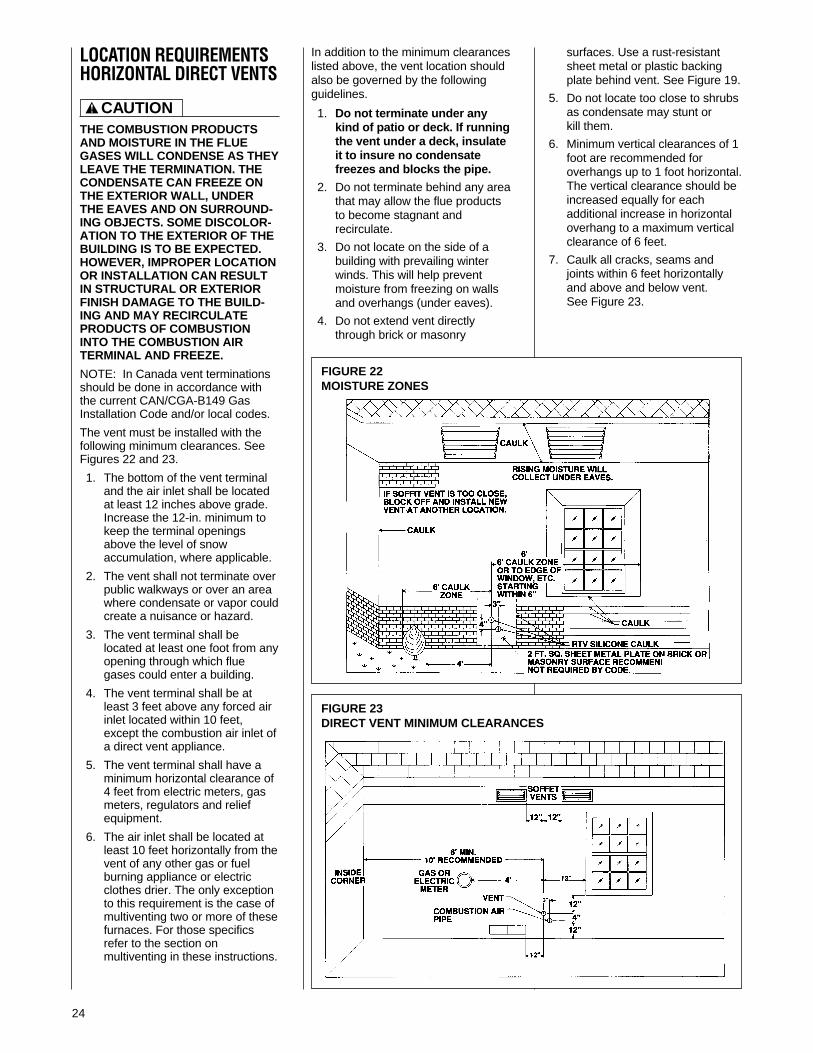
1. Locate the bottom of the ventterminal at least 12 inches abovegrade. Increase the 12-in.minimum to keep the terminalopenings above the level of snowaccumulation, where applicable.
2. The vent shall not terminate overpublic walkways or over an areawhere condensate or vapor couldcreate a nuisance or hazard.
3. 4 feet below, 4 feet horizontallyfrom, or 1 foot above any door,window soffit, under eave vent orgravity air inlet to the building.
4. The vent terminal shall have aminimum horizontal clearance of4 feet from electric meters, gasmeters, regulators and reliefequipment.
5. 6 feet from an inside cornerformed by two exterior walls –10 feet is the recommendeddistance.
6. Locate it 3 feet above any forcedair inlet located within 10 feet.Any fresh air or make-up air inlet,such as for a dryer or furnacearea, is considered a forced airinlet.
! CAUTION
FIGURE 16NON-DIRECT VENT TERMINATION CLEARANCES
I133
SOFFITVENTS
FRESHAIRINTAKE
*NOTE: FOR DISTANCES OVER 10* NOVERTICAL RESTRICTIONS APPLY.
INSIDECORNER
ELECTRICMETER
10* RECOMMENDED
12( MIN.
UP TO10**
4*
4*
3*
4*
4*
4*
6*
7. Avoid areas where drippingcondensate may cause problems,such as above planters, patios, oradjacent to windows wheresteam may cause fogging.
In addition to the minimum clearanceslisted above, the vent location shouldalso be governed by the followingguidelines.
1. Do not terminate under any kindof patio or deck. If running thevent under a deck, insulate it toinsure no condensate freezesand blocks the pipe.
2. Do not locate on the side of abuilding with prevailing winterwinds. This will help preventmoisture from freezing on wallsand overhangs (under eaves).
3. Do not extend vent directlythrough brick or masonrysurfaces. Use a rust-resistantsheet metal or plastic backingplate behind vent.
4. Do not locate too close to shrubsas condensate may stunt or killthem.
5. Minimum vertical clearances of 1foot are recommended foroverhangs up to 1 foot horizontal.The vertical clearance should beincreased equally for eachadditional increase in horizontaloverhang to a maximum verticalclearance of 6 feet.
6. Caulk all cracks, seams andjoints within 6 feet horizontallyand above and below vent.
19
DIRECT VENTINSTALLATIONS
READ AND FOLLOW ALLINSTRUCTIONS IN THIS SECTION.FAILURE TO PROPERLY VENTTHIS FURNACE CAN CAUSECARBON MONOXIDE POISONINGOR AN EXPLOSION OR FIRE,RESULTING IN PROPERTYDAMAGE, PERSONAL INJURYOR DEATH.
Direct vent installations require adedicated combustion air and ventingsystem. All air for combustion is takenfrom the outside atmosphere and allcombustion products are dischargedto the outdoors. Therefore, noventilation or combustion airopenings are required.
IMPORTANT: The plastic combustionair and venting components are ofSchedule 40 PVC. If using ABSpiping ensure that the solvent cementis compatible for joining PVC to ABScomponents or use a mechanicalconnection that can withstand thevent temperatures and are corrosionresistant.
INSTALLATION GUIDELINESAll exhaust piping must be installed incompliance with Part 7, “Venting ofEquipment,” of the latest edition of theNational Fuel Gas Code NPFA54/ANSI Z223.1-, CAN/CGA-B149, localcodes or ordinances and theseinstructions.
1. Vertical piping is preferred.
2. All horizontal piping must slopeupward a minimum of 1/4 inchper foot of run so that condensatedrains toward the furnace.
3. All horizontal runs must besupported at least every 4 feet.No sags or dips are permitted.
4. IMPORTANT: DO NOT COM-MON VENT WITH ANY OTHERAPPLIANCE. DO NOT INSTALLIN THE SAME CHASE ORCHIMNEY WITH A METAL ORHIGH TEMPERATURE PLAS-TIC PIPE FROM ANOTHERGAS OR FUEL-BURNINGAPPLIANCE UNLESS THEREQUIRED MINIMUMCLEARANCES TOCOMBUSTIBLES AREMAINTAINED BETWEEN THEPVC PIPE AND OTHER PIPES.
5. All vent runs through uncon-ditioned spaces where below-freezing temperatures areexpected should be insulatedwith 1-in. thick, medium-density,foil-faced fiberglass. Anequivalent “arm-a-flex” or “rub-a-tex” insulation may also be usedas long as there is no heat tapeapplied to the vent pipe. Forhorizontal runs where water maycollect, wrap the vent pipe withself-regulating 3 or 5 watt heattape. The heat tape must be
! WARNING
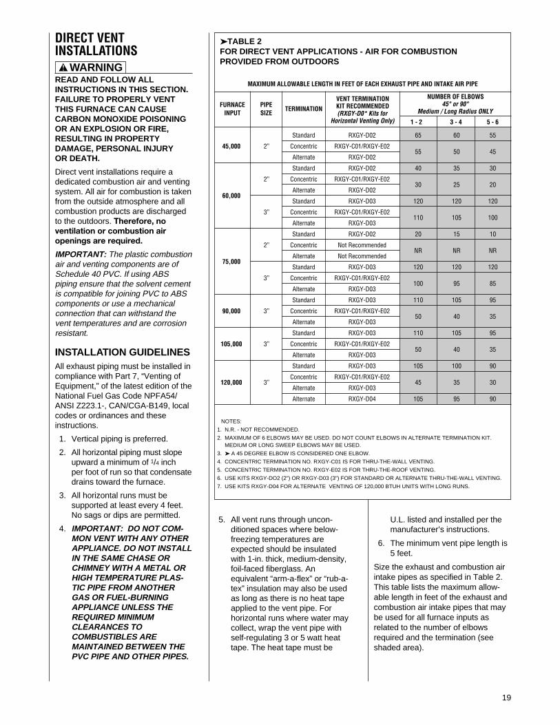
➤TABLE 2FOR DIRECT VENT APPLICATIONS - AIR FOR COMBUSTION PROVIDED FROM OUTDOORS
MAXIMUM ALLOWABLE LENGTH IN FEET OF EACH EXHAUST PIPE AND INTAKE AIR PIPE
U.L. listed and installed per themanufacturer’s instructions.
6. The minimum vent pipe length is5 feet.
Size the exhaust and combustion airintake pipes as specified in Table 2.This table lists the maximum allow-able length in feet of the exhaust andcombustion air intake pipes that maybe used for all furnace inputs asrelated to the number of elbowsrequired and the termination (seeshaded area).
FURNACEINPUT
PIPESIZE
TERMINATION
VENT TERMINATIONKIT RECOMMENDED(RXGY-D0* Kits for
Horizontal Venting Only) 1 - 2 3 - 4 5 - 6
NUMBER OF ELBOWS45° or 90°
Medium / Long Radius ONLY
Standard RXGY-D02 65 60 55
45,000 2” Concentric RXGY-C01/RXGY-E0255 50 45
Alternate RXGY-D02
Standard RXGY-D02 40 35 30
2” Concentric RXGY-C01/RXGY-E0230 25 20
Alternate RXGY-D0260,000
Standard RXGY-D03 120 120 120
3” Concentric RXGY-C01/RXGY-E02110 105 100
Alternate RXGY-D03
Standard RXGY-D02 20 15 10
2” Concentric Not RecommendedNR NR NR
Alternate Not Recommended75,000
Standard RXGY-D03 120 120 120
3” Concentric RXGY-C01/RXGY-E02100 95 85
Alternate RXGY-D03
Standard RXGY-D03 110 105 95
90,000 3” Concentric RXGY-C01/RXGY-E0250 40 35
Alternate RXGY-D03
Standard RXGY-D03 110 105 95
105,000 3” Concentric RXGY-C01/RXGY-E0250 40 35
Alternate RXGY-D03
Standard RXGY-D03 105 100 90
120,000 3”Concentric RXGY-C01/RXGY-E02
45 35 30Alternate RXGY-D03
Alternate RXGY-D04 105 95 90
NOTES:
1. N.R. - NOT RECOMMENDED.
2. MAXIMUM OF 6 ELBOWS MAY BE USED. DO NOT COUNT ELBOWS IN ALTERNATE TERMINATION KIT.MEDIUM OR LONG SWEEP ELBOWS MAY BE USED.
3. ➤ A 45 DEGREE ELBOW IS CONSIDERED ONE ELBOW.
4. CONCENTRIC TERMINATION NO. RXGY-C01 IS FOR THRU-THE-WALL VENTING.
5. CONCENTRIC TERMINATION NO. RXGY-E02 IS FOR THRU-THE-ROOF VENTING.
6. USE KITS RXGY-DO2 (2") OR RXGY-D03 (3") FOR STANDARD OR ALTERNATE THRU-THE-WALL VENTING.
7. USE KITS RXGY-D04 FOR ALTERNATE VENTING OF 120,000 BTUH UNITS WITH LONG RUNS.

20
➤ALTERNATETERMINATIONSALTERNATE HORIZONTALDIRECT VENT TERMINATIONS
KIT NOS. RXGY-D02, -D03AND -D04
The combustion air and exhaustterminations may be raised amaximum of 60 inches above thewall penetration to maintain therequired 12 inch clearance abovegrade or snow level. See Figure 17.Size the pipe length according toTable 2.
IMPORTANT: The followingguidelines must be met whenextending beyond 24 inches of pipeon the exterior of the structure:
• Size the entire vent systemaccording to the concentric, notstandard, termination shown inTable 2.
COMBUSTION AIR FORDIRECT VENTINSTALLATIONSTHE COMBUSTION AIR SYSTEMDESIGNED FOR THIS FURNACEMUST BE USED.
When this furnace is installed as adirect vent forced air furnace, allcombustion air is supplied directly tothe burner through a special air inletsystem outlined in these instructions.This system consists of field-suppliedSchedule 40 or 26 SDR-PVC pipeand one of the following horizontalvent termination kits: RXGY-D02,RXGY-D03, RXGY-D04, RXGY-C01or RXGY-E02.
NOTE: Schedule 40 ABS-DWV pipeand fittings may be used as analternate to PVC pipe for thecombustion air inlet and vent pipes.
The combustion air for this furnace issupplied directly from the outdoorsthrough the combustion air inletsystem.
When the furnace is installed in thesame space with other gasappliances, such as a water heater,be sure there is an adequate supplyof combustion and ventilation air forthe other appliances. Do not delete orreduce the combustion air supplyrequired by the other gas appliancesin this space. See Z223.1, NationalFuel Gas Code (NFPA54) orCAN/CGA-B149.1 and .2 for deter-mining the combustion air require-ments for gas appliances. Anunconfined space must have at least50 cubic feet (volume) for each1,000 BTUH of the total input of allappliances in the space. If the openspace containing the appliances is ina building with tight construction(contemporary construction), outsideair may still be required for theappliances to burn and vent properly.Outside air openings should be sizedthe same as for a confined space.
STANDARD TERMINATIONSSTANDARD VERTICALTERMINATIONS
COMBUSTION AIR PIPING
Use two medium-radius sweepelbows to keep the inlet downward toprevent entry of rain. See Figure 20for the proper relationship ofcombustion air to exhausttermination.
STANDARD HORIZONTALTERMINATIONS
COMBUSTION AIR PIPING
When 3-in. pipe is used between thefurnace and outside wall, reduce itto 2 inches before penetrating thewall. Up to 18 inches of 2-in. pipemay be used inside the wall.
The standard horizontal intake airtermination for all models is a 2-in.PVC coupling with a wind deflectorvane (provided) attached. Cut a21/4-in. length of 2-in. PVC pipe.Connect this pipe and another 2-in.PVC coupling to the coupling at thewall. The outer coupling mustterminate 4 inches from the wall. SeeFigure 21, Detail B, for vane location.Attach vane in vertical position withPVC solvent.
IMPORTANT: To ensure properfurnace operation, the suppliedvane must be installed in thevertical position as shown in Figure21, Detail B.
The combustion air inlet terminalmust be located with respect to theexhaust terminal as shown in Figure21, Detail C.
➤ IMPORTANT: All furnaces withhorizontal air intakes, except thoseusing horizontal concentric vent kitRXGY-C01, must have a drain teeassembly and trap installed asclose to the furnace as possible.This is to drain any water that maybe in the combustion air pipe toprevent it from entering thefurnace combustion chamber.
These parts are included in kitsRXGY-D02 (for 2-in. pipe), RXGY-D03 (for 3-in. pipe) and RXGY-D04(special for the 120,000 BTUfurnace installed with the alternatehorizontal termination). Attach thetrap to the bottom of the tee withPVC solvent. Connect the otherend to a suitable drain, as to thedownstream of a condensate trapon the furnace.
STANDARD VERTICALTERMINATIONS
EXHAUST VENT PIPING
Vertical through-the-roof vent appli-cations do not require an exhaustterminal. The exhaust vent mustterminate at least 12 inches abovethe combustion intake air termination.The exhaust vent for models withinputs of 90,000 through 120,000BTUH is 2-in. PVC pipe 120,000BTUH models with excessively long
runs require 21⁄2(. Refer to Table 2 forproper application. This mustbe reduced to 1( or 11⁄2( the last12 inches for models with inputs of45,000 through 75,000 BTUH.See Figure 22.
STANDARD HORIZONTALTERMINATIONS
EXHAUST PIPING
For direct vent systems the standardtermination is 2-in. PVC pipeextending 12 inches from the wall forfurnaces with inputs from 90,000 to120,000 BTUH. Install a 2-in. couplingat the outside wall to prevent thetermination from being pushedinward. When 3-in. pipe is usedbetween the furnace and outside wall,reduce to 2 inches before penetratingthe wall. The standard termination is11/2 -in. PVC pipe extending outward12 inches from the wall for modelswith inputs of 45,000 to 75,000BTUH. Install a 2-in. to 11/2-in.coupling at the outside wall to preventpushing the termination back into thewall. See Figure 21, Detail B.
The combustion air and exhaustterminations must be at least 12inches above grade and must beoriented with respect to each other asshown in Figure 21. Refer to sectionon alternate venting options whenhigher snow levels are anticipated.

21
FIGURE 17ALTERNATE HORIZONTAL DIRECT VENT TERMINATION
SEE DETAIL A
60( MAX.
PIPESUPPORTSTRAP
3( MAX.NOTE: 3-1/2(MAX. WHEND04 KIT ISUSED.
EXHAUST VENT FORMODELS WITH
INPUT OF 45,000 THRU75,000 BTU
DETAIL A
EXHAUST VENT21/2" PVC FOR MODELS WITH 120,000 BTU INPUT(KIT NO. RXGY-D04)
2" PVC FOR MODELS WITH INPUTS OF 90,000 THRU 120,000BTU. REDUCE TO 11/2" FOR MODELS WITH INPUTS OF 45,000THRU 75,000 BTU. ELBOWS AND RISERS ARE 2" PVC.
INTAKE VENT21/2" PVC FOR MODELS WITH120,000 BTU INPUT.2" PVC ELBOWS AND RISERMODELS WITH INPUTS OF 45,000THRU 105,000 BTU.USE KIT NO. RXGY-D02 WHEN 2" PIPEIS USED BETWEEN FURNACE ANDOUTSIDE WALL. USE KIT NO. RXGY-D03WHEN 3" PIPE IS USED.
FIGURE 18VERTICAL CONCENTRIC VENT KIT - RXGY - E02
12" FIXED
48" MAX.INLET AIR12" ABOVE
AVERAGE SNOWACCUMULATION
INSTALL ROOFFLASHING
ROOF LINE
INLET AIR PIPE
2"
USE 2" x 3" INCREASERIF VENT IS 3" PIPE(FIELD SUPPLIED)
VENT FROMFURNACE
INLET AIR FROMFURNACE, USE3" x 2" BUSHINGIF INLET IS 2" PIPE(FIELD SUPPLIED)
➀
➁
➂
➄
➃
➅
➆
➀➁➂➃➄➅➆
2" SCH40 PVC PIPE
3" TYPE SDR 26 PVC PIPE
2" x 3" BUSHING (MODIFIED)
3" x 3" x 3" WYE
2" x 4" COUPLING (MODIFIED)
3" x 45° STREET ELBOW
2" COUPLING(FIELD SUPPLIED)
• Insulate the entire length of ventpipe, between the elbow where thepipe exits the wall and the elbowwhere the termination is made, witha closed-cell insulation, such as“Arm-a-Flex” or “Rub-a-Tex” with aminimum of 1/2( thickness.
• All elbows installed on the exteriorof the building must be of the longsweep nature.
• As required for the horizontal pipingran within the structure, any piperan horizontal outside the structuremust slope upward a minimum of1/4( per foot run so that condensatedrains toward the furnace.
From the top elbow in the exhaustpipe, extend a length of PVC pipeoutward so that it terminates exactly12 inches from the wall. See Figure17. Reduce the termination pipeextension to is 11/2 inch pipe for45,000 BTUH through 75,000 BTUHunits.
The 45,000 BTUH unit only uses kitRXGY-D02. The 60,000 BTUH and75,000 BTUH units may use kitsRXGY-D02 or RXGY-D03 dependingon pipe lengths and number ofelbows. Use kit RXGY-D03 with90,000 BTUH through 120,000 BTUHunits. The RXGY-D04 kit onlyapplies to the 120,000 BTUH unitusing an alternate termination andexcessively long runs. See Table 2.
The following are parts lists for theRXGY-D02, RXGY-D03 and RXGY-D04 alternate horizontal direct venttermination kits:
RXGY-D021. 2-in. tee with reducer assembly2. 1/2-in. PVC 6-in. dia. trap3. PVC vane4. 2-in. PVC elbow5. 11/2-in. PVC nipple with coupling6. PVC strap7. vent template
RXGY-D031. 3-in. tee with reducer assembly2. 1/2-in. PVC 6-in. dia. trap3. PVC vane4. 2-in. PVC elbow5. PVC strap6. vent template
I339
I338
12( FROM W
ALL
22
HORIZONTAL CONCENTRICTERMINATION
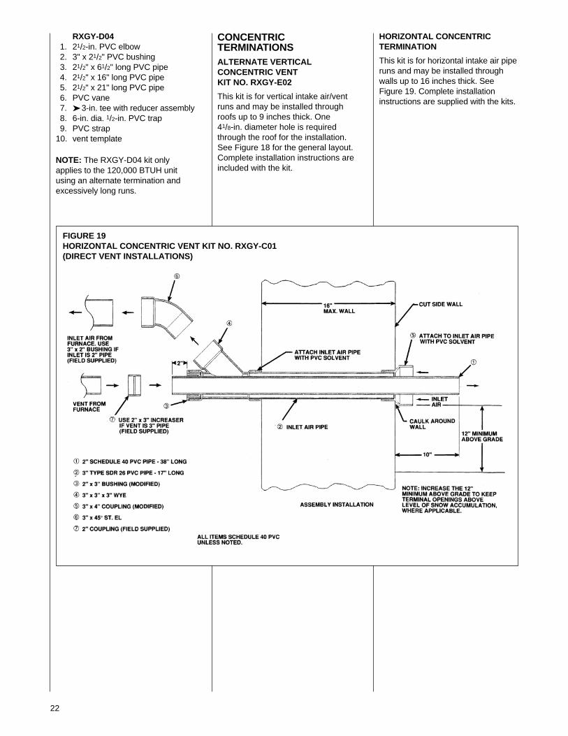
This kit is for horizontal intake air piperuns and may be installed throughwalls up to 16 inches thick. SeeFigure 19. Complete installationinstructions are supplied with the kits.
FIGURE 19HORIZONTAL CONCENTRIC VENT KIT NO. RXGY-C01(DIRECT VENT INSTALLATIONS)
RXGY-D041. 21/2-in. PVC elbow2. 3" x 21/2" PVC bushing3. 21/2" x 61/2" long PVC pipe4. 21/2" x 16" long PVC pipe5. 21/2" x 21" long PVC pipe6. PVC vane7. ➤ 3-in. tee with reducer assembly8. 6-in. dia. 1/2-in. PVC trap9. PVC strap
10. vent template
NOTE: The RXGY-D04 kit onlyapplies to the 120,000 BTUH unitusing an alternate termination andexcessively long runs.
CONCENTRICTERMINATIONSALTERNATE VERTICALCONCENTRIC VENTKIT NO. RXGY-E02
This kit is for vertical intake air/ventruns and may be installed throughroofs up to 9 inches thick. One41/8-in. diameter hole is requiredthrough the roof for the installation.See Figure 18 for the general layout.Complete installation instructions areincluded with the kit.
23
FIGURE 20STANDARD VERTICAL DIRECT VENTINGUPFLOW MODEL SHOWN (TYPICAL FOR DOWNFLOW MODELS)
FIGURE 21STANDARD HORIZONTAL DIRECT VENTINGUPFLOW MODEL SHOWN (TYPICAL FOR DOWNFLOW MODELS)
I407
EXHAUSTTERMINATION
➀
➁
3" MAX.SEPARATION
COMBUSTION AIRPIPE
12" MIN.SEPARATION
12" MIN. ABOVEROOF LEVELROOF LINEEXHAUST PIPE
COMBUSTIONAIR PIPE
SUPPLY AIR
RETURN AIR
EXHAUST VENT
➂
➃
3"MAX.
EXHAUSTVENT
ROOF LINE
COMBUSTIONAIR PIPE
12"MIN.
12" MIN. ANTICIPATEDSNOW LEVEL
COMBUSTIONAIR PIPE
3"MAX.EXHAUST
VENT
12"MIN.
12" MIN.
3"
MAX.
12" MIN. 12" MIN. ABOVE
ANTICIPATED SNOW LEVEL
➄
NOTES:
➀ THE COMBUSTION AIR PIPEMUST TERMINATE IN THESAME PRESSURE ZONE ASTHE EXHAUST PIPE.
➁ INCREASE THE 12-IN. MINIMUMTO KEEP TERMINAL OPENING ABOVEANTICIPATED LEVEL OF SNOWACCUMULATION WHEREAPPLICABLE.
➂ WHEN 3-IN. DIAM. PIPE IS USED,REDUCE TO 2-IN. DIAMETER BEFOREPENETRATING ROOF. A MAXIMUM OF18 IN. OF 2-IN. PIPE MAY BE USEDBEFORE PASSING THROUGH ROOF.
➃ SUPPORT VERTICAL PIPE EVERY 6FEET.
➄ EXHAUST TERMINATION - TERMINATETHE LAST 12 INCHES WITH 2( PVCPIPE ON 90,000 THROUGH 120,000BTUH MODELS. REDUCE ANDTERMINATE THE LAST 12 INCHESWITH 11⁄2( PVC PIPE ON 45,000THROUGH 75,000 BTUH MODELS.
PITCHED ROOF INSTALLATIONS
NOTES:
➀ SUPPORT HORIZONTAL PIPEEVERY FOUR FEET.
➁ WHEN 3 IN. PIPE IS USED REDUCE TO 2 IN.BEFORE PENETRATING OUTSIDE WALL.
➂ 18 IN. MAXIMUM. 2 IN. DIAMETER PIPE MAYBE USED INSIDE THE WALL.
➃ DETAIL “A” - EXHAUST TERMINATIONTERMINATE THE LAST 12 INCHES WITH 2(PVC PIPE ON 90,000 THROUGH 120,000BTUH MODELS. REDUCE AND TERMINATETHE LAST 12 INCHES WITH 11⁄2( PVC PIPEON 45,000 THROUGH 75,000 BTUH MODELS.
➄ INCREASE THE 12 IN. MINIMUM ABOVEGRADE TO KEEP TERMINAL OPENINGSABOVE ANTICIPATED LEVEL OF SNOWACCUMULATION WHERE APPLICABLE.
➅ DETAIL “B”, INSTALL WIND DEFLECTORVANE IN 2 IN. PVC COUPLING IN VERTICLEPOSITION USING PVC SOLVENT.THE COMBUSTION AIR TERMINATION MUSTBE IN THE SAME PRESSURE ZONE AS THEEXHAUST TERMINATION.
3(
12(
4(
4(
SEE DETAIL A
VANE 2( PVCCOUPLING
12( MIN. ABOVEGRADE LEVEL ➄
SEE DETAIL B
2( OR 3( TEEW/DRAIN TRAP
RETURN AIR
TRAP
SUPPLY AIR
EXHAUST PIPE
COMBUSTION AIR PIPE
CONNECTTO DRAIN
12(
4(
EXHAUST
INTAKE OPTIONALINTAKE
DETAIL CEXHAUST / INTAKE RELATIONSHIP
EXHAUST TERMINATION➃ DETAIL A
COMBUSTION AIR TERMINATION➅ DETAIL B
➀ ➁➂
I407
24
LOCATION REQUIREMENTSHORIZONTAL DIRECT VENTS
THE COMBUSTION PRODUCTSAND MOISTURE IN THE FLUEGASES WILL CONDENSE AS THEYLEAVE THE TERMINATION. THECONDENSATE CAN FREEZE ONTHE EXTERIOR WALL, UNDERTHE EAVES AND ON SURROUND-ING OBJECTS. SOME DISCOLOR-ATION TO THE EXTERIOR OF THEBUILDING IS TO BE EXPECTED.HOWEVER, IMPROPER LOCATIONOR INSTALLATION CAN RESULTIN STRUCTURAL OR EXTERIORFINISH DAMAGE TO THE BUILD-ING AND MAY RECIRCULATEPRODUCTS OF COMBUSTIONINTO THE COMBUSTION AIRTERMINAL AND FREEZE.
NOTE: In Canada vent terminationsshould be done in accordance withthe current CAN/CGA-B149 GasInstallation Code and/or local codes.
The vent must be installed with thefollowing minimum clearances. SeeFigures 22 and 23.
1. The bottom of the vent terminaland the air inlet shall be locatedat least 12 inches above grade.Increase the 12-in. minimum tokeep the terminal openingsabove the level of snowaccumulation, where applicable.
2. The vent shall not terminate overpublic walkways or over an areawhere condensate or vapor couldcreate a nuisance or hazard.
3. The vent terminal shall belocated at least one foot from anyopening through which fluegases could enter a building.
4. The vent terminal shall be atleast 3 feet above any forced airinlet located within 10 feet,except the combustion air inlet ofa direct vent appliance.
5. The vent terminal shall have aminimum horizontal clearance of4 feet from electric meters, gasmeters, regulators and reliefequipment.
6. The air inlet shall be located atleast 10 feet horizontally from thevent of any other gas or fuelburning appliance or electricclothes drier. The only exceptionto this requirement is the case ofmultiventing two or more of thesefurnaces. For those specificsrefer to the section onmultiventing in these instructions.
In addition to the minimum clearanceslisted above, the vent location shouldalso be governed by the followingguidelines.
1. Do not terminate under anykind of patio or deck. If runningthe vent under a deck, insulateit to insure no condensatefreezes and blocks the pipe.
2. Do not terminate behind any areathat may allow the flue productsto become stagnant andrecirculate.
3. Do not locate on the side of abuilding with prevailing winterwinds. This will help preventmoisture from freezing on wallsand overhangs (under eaves).
4. Do not extend vent directlythrough brick or masonry
surfaces. Use a rust-resistantsheet metal or plastic backingplate behind vent. See Figure 19.
5. Do not locate too close to shrubsas condensate may stunt orkill them.
6. Minimum vertical clearances of 1foot are recommended foroverhangs up to 1 foot horizontal.The vertical clearance should beincreased equally for eachadditional increase in horizontaloverhang to a maximum verticalclearance of 6 feet.
7. Caulk all cracks, seams andjoints within 6 feet horizontallyand above and below vent.See Figure 23.
FIGURE 22MOISTURE ZONES
FIGURE 23DIRECT VENT MINIMUM CLEARANCES
! CAUTION
25
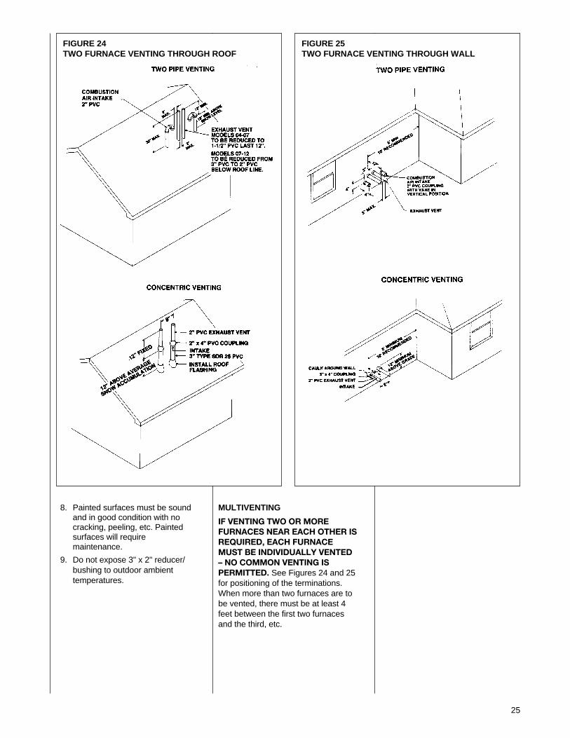
FIGURE 24TWO FURNACE VENTING THROUGH ROOF
FIGURE 25TWO FURNACE VENTING THROUGH WALL
8. Painted surfaces must be soundand in good condition with nocracking, peeling, etc. Paintedsurfaces will requiremaintenance.
9. Do not expose 3" x 2" reducer/bushing to outdoor ambienttemperatures.
MULTIVENTING
IF VENTING TWO OR MOREFURNACES NEAR EACH OTHER ISREQUIRED, EACH FURNACEMUST BE INDIVIDUALLY VENTED– NO COMMON VENTING ISPERMITTED. See Figures 24 and 25for positioning of the terminations.When more than two furnaces are tobe vented, there must be at least 4feet between the first two furnacesand the third, etc.
26
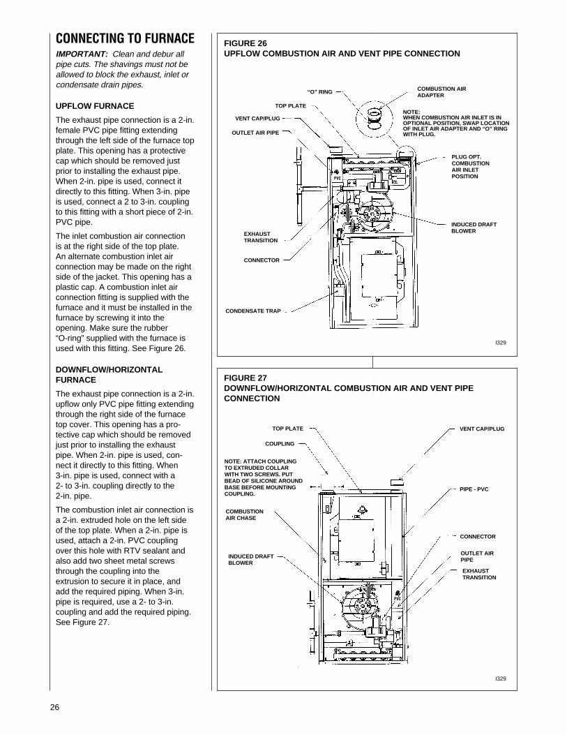
CONNECTING TO FURNACEIMPORTANT: Clean and debur allpipe cuts. The shavings must not beallowed to block the exhaust, inlet orcondensate drain pipes.
UPFLOW FURNACE
The exhaust pipe connection is a 2-in.female PVC pipe fitting extendingthrough the left side of the furnace topplate. This opening has a protectivecap which should be removed justprior to installing the exhaust pipe.When 2-in. pipe is used, connect itdirectly to this fitting. When 3-in. pipeis used, connect a 2 to 3-in. couplingto this fitting with a short piece of 2-in.PVC pipe.
The inlet combustion air connectionis at the right side of the top plate.An alternate combustion inlet airconnection may be made on the rightside of the jacket. This opening has aplastic cap. A combustion inlet airconnection fitting is supplied with thefurnace and it must be installed in thefurnace by screwing it into theopening. Make sure the rubber“O-ring” supplied with the furnace isused with this fitting. See Figure 26.
DOWNFLOW/HORIZONTALFURNACE
The exhaust pipe connection is a 2-in.upflow only PVC pipe fitting extendingthrough the right side of the furnacetop cover. This opening has a pro-tective cap which should be removedjust prior to installing the exhaustpipe. When 2-in. pipe is used, con-nect it directly to this fitting. When3-in. pipe is used, connect with a2- to 3-in. coupling directly to the2-in. pipe.
The combustion inlet air connection isa 2-in. extruded hole on the left sideof the top plate. When a 2-in. pipe isused, attach a 2-in. PVC couplingover this hole with RTV sealant andalso add two sheet metal screwsthrough the coupling into theextrusion to secure it in place, andadd the required piping. When 3-in.pipe is required, use a 2- to 3-in.coupling and add the required piping.See Figure 27.
FIGURE 26UPFLOW COMBUSTION AIR AND VENT PIPE CONNECTION
FIGURE 27DOWNFLOW/HORIZONTAL COMBUSTION AIR AND VENT PIPECONNECTION
VENT CAP/PLUG
VENT CAP/PLUG
OUTLET AIR PIPE
PIPE - PVC
CONNECTOR
CONNECTOR
EXHAUSTTRANSITION
EXHAUSTTRANSITION
PLUG OPT.COMBUSTIONAIR INLETPOSITION
COMBUSTION AIRADAPTER
TOP PLATE
TOP PLATE
“O” RING
COUPLING
NOTE: ATTACH COUPLINGTO EXTRUDED COLLARWITH TWO SCREWS. PUTBEAD OF SILICONE AROUNDBASE BEFORE MOUNTINGCOUPLING.
COMBUSTIONAIR CHASE
INDUCED DRAFTBLOWER
INDUCED DRAFTBLOWER
CONDENSATE TRAP
NOTE:WHEN COMBUSTION AIR INLET IS INOPTIONAL POSITION, SWAP LOCATIONOF INLET AIR ADAPTER AND “O” RINGWITH PLUG.
PVC
PVC
OUTLET AIRPIPE
I329
I329
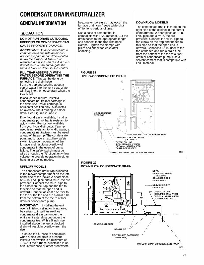
FIGURE 29DOWNFLOW CONDENSATE DRAIN
CONDENSATE DRAIN/NEUTRALIZER
27
FIGURE 28UPFLOW CONDENSATE DRAIN
GENERAL INFORMATION
DO NOT RUN DRAIN OUTDOORS.FREEZING OF CONDENSATE CANCAUSE PROPERTY DAMAGE.IMPORTANT: Do not connect into acommon drain line with an air con-ditioner evaporator coil drain locatedbelow the furnace. A blocked orrestricted drain line can result in over-flow of the coil pan and negate thefurnace blocked drain shutoff control.FILL TRAP ASSEMBLY WITHWATER BEFORE OPERATING THEFURNACE. This can be done byremoving the drain hosefrom the trap and pouring about acup of water into the vent trap. Waterwill flow into the house drain when thetrap is full.If local codes require, install acondensate neutralizer cartridge inthe drain line. Install cartridge inhorizontal position only. Also installan overflow line if routing to a floordrain. See Figures 28 and 29. If no floor drain is available, install acondensate pump that is resistant toacidic water. Pumps are availablefrom your local distributor. If pumpused is not resistant to acidic water, acondensate neutralizer must be usedahead of the pump. The condensatepump must have an auxiliary safetyswitch to prevent operation of thefurnace and resulting overflow ofcondensate in the event of pumpfailure. The safety switch must bewired through the “R” circuit only (lowvoltage) to provide operation in eitherheating or cooling modes.
UPFLOW MODELSThe condensate drain trap is locatedin the blower compartment on the left-hand side of the jacket. A short pieceof 1/2-in. PVC pipe and a 1/2-in. tee areprovided. Connect the 1/2-in. pipe tothe elbow on the trap and the tee tothis pipe so that the open end isupward. Connect at least a 5( riser tothe top of the tee and run a drain tubefrom the bottom of the tee to a floordrain or condensate pump. IMPORTANT: If installing the unitover a finished ceiling or living area,be certain to install an auxiliarycondensate drain pan under theentire unit extending out under thecondensate tee. With a 5 inch riserinstalled above the tee, a blockeddrain will result in overflow from theriser.To cause the furnace to shut downwhen a blocked drain is present,install a riser which is a minimum of1013⁄16(. If the furnace is installed in anattic, crawlspace or other area where
freezing temperatures may occur, thefurnace drain can freeze while shutoff for long periods of time. Use a solvent cement that iscompatible with PVC material. Cut thedrain hoses to the appropriate lengthand connect to the trap with hoseclamps. Tighten the clamps withpliers and check for leaks afterattaching.
DOWNFLOW MODELSThe condensate trap is located on theright side of the cabinet in the burnercompartment. A short piece of 1/2-in.PVC pipe and a 1/2-in. tee areprovided. Connect the 1/2-in. pipe tothe elbow on the trap and the tee tothis pipe so that the open end isupward. Connect a 51⁄2-in. riser to thetop of the tee and run a drain tubefrom the bottom of the tee to a floordrain or condensate pump. Use asolvent cement that is compatible withPVC material.
! CAUTION
NEUTRALIZER CARTRIDGE(OPTIONAL)
TO FLOOR DRAIN OR CONDENSATE PUMP
NOTE:DRAIN VENT NEEDSTO BE ABOVECOLLECTOR BOXDRAIN SPOUT.
MINIMUM HEIGHTOPEN TOP
CONDENSATE TRAP
DRAIN LINE
I408
OVERFLOW LINE(REQUIRED ONLY WHENOPTIONAL NEUTRALIZERCARTRIDGE IS USED.)
I408
MINIMUM HEIGHTOPEN TOP
DRAIN LINE CONDENSATE TRAP
TO FLOOR DRAIN OR CONDENSATE PUMP
NEUTRALIZER CARTRIDGE(OPTIONAL)
OVERFLOW LINE(REQUIRED ONLY WHENOPTIONAL NEUTRALIZERCARTRIDGE IS USED.)
5(

28
➤ FIGURE 30UPFLOW OPPOSITE SIDE CONDENSATE TRAP CONNECTION
FIGURE 31DOWNFLOW OPPOSITE SIDE CONDENSATE TRAP CONNECTION
REVERSING THE TRAPUPFLOW UNITS
The trap may be moved to the rightside for right side drainage. Open theknockout for the drain on the rightside of the cabinet. Remove thebracket holding the trap from the leftside. Seal the left side drain hole witha plug provided in the cloth bag withthe furnace. Position the mountingbracket and trap so that the drainelbow is centered in the hole onthe right. See Figure 30.
Drill two holes in the cabinet to mountthe bracket. Mount the trap andbracket to the right side with the drainelbow pointing through the knockout.Connect the 1/2-in. pipe and tee asnoted above. Route the drain hosesbehind the control box, cut to theappropriate length, and connect to thetrap with hose clamps.
IMPORTANT: DO NOT ALLOWANY SAGS OR KINKS IN THEHOSES. This prevents propercondensate flow.
IMPORTANT: Do not connect intoa common drain line with an airconditioner evaporator coil drainlocated above the furnace. A blockedor restricted drain line can result inoverflow of the coil pan and negatethe furnace blocked drain shutoffcontrol.
DOWNFLOW UNITS
To convert to left side drainage, firstremove the drainage hoses from thetrap. Remove the trap from itsmounting bracket, rotate it 180°, andmount in place with the drainageelbow pointing to the left. Reattachthe drain hoses. Remove the plasticdrainage knockout from the left side.See Figure 31.
IMPORTANT: When changing to theleft side, interchange the rubberbushing on the right side with the holeplug on the left side. The hole plugmust be in place to assure that thecontrol compartment is sealed.
A length of 1/2-in. PVC pipe isprovided for left hand drainage. Glueone end of the pipe to the elbow inthe trap. Cut the pipe so that itextends through the left cabinet sideone inch. Connect the 1/2-in. tee to thepipe with a 5-in. riser and drain tubeas listed above. Use the plastic plugfrom the left side drainage knockoutto seal the right side drainageknockout.
IMPORTANT: Do not connect intoa common drain line with an airconditioner evaporator coil drainlocated above the furnace. A blockedor restricted drain line can result inoverflow of the coil pan and negatethe furnace blocked drain shutoffcontrol.
DRAINVENT
DRAINEXTENSION
TEE
TO FLOORDRAIN OR
CONDENSATE PUMP
CUT DRAIN HOSES ASREQUIREDAND CONNECT TOINLETS ON TOPOF CONDENSATETRAP
DRAINVENT
TEE
DRAINEXTENSION
PROPER DRAIN SLOPE REQUIRED(NO KINKS ALLOWED)
CONDENSATE TRAPSHEETMETALCONTROL BOX
TO FLOORDRAIN
CONDENSATE TRAP
ROTATETRAP 180°AND INSTALLRIGID PIPE(SUPPLIED)FROMELBOW TOOPPOSITESIDE OFJACKET
FILLING THE TRAPFILL THE TRAP ASSEMBLY WITHWATER BEFORE OPERATING THEFURNACE. Do this by removing thedrain hose from the trap or from theconnection to the secondary coil.Pour about a cup of water into thevent trap. Any excess water flows intothe house drain when the trap is full.
I394
I394
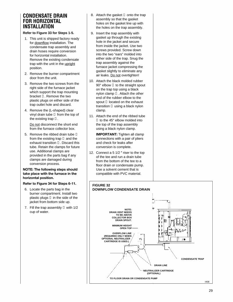
29
8. Attach the gasket ➇ onto the trapassembly so that the gasketholes on the gasket line up withthe holes on the trap assembly.
9. Insert the trap assembly withgasket up through the existinghole in the jacket and securefrom inside the jacket. Use twoscrews provided. Screw downinto the two “ears” molded intoeither side of the trap. Snug thetrap assembly against thefurnace jacket compressing thegasket slightly to eliminate anyair leaks. Do not overtighten!
10. Attach the black molded rubber90° elbow ➈ to the straight spouton the trap top using a blacknylon clamp ➉. Attach the otherend of the rubber elbow to thespout ➀ located on the exhausttransition ➄ using a black nylonclamp.
11. Attach the end of the ribbed tube➂ to the 45° elbow molded intothe top of the trap assemblyusing a black nylon clamp.
IMPORTANT: Tighten all clampconnections with a pair of pliersand check for leaks afterconversion is complete.
12. Connect a 5 1/2 ( riser to the topof the tee and run a drain tubefrom the bottom of the tee to afloor drain or condensate pump.Use a solvent cement that iscompatible with PVC material.
CONDENSATE DRAINFOR HORIZONTALINSTALLATIONRefer to Figure 33 for Steps 1-5.
1. This unit is shipped factory readyfor downflow installation. Thecondensate trap assembly anddrain hoses require conversionfor horizontal installation.Remove the existing condensatetrap with the unit in the uprightposition.
2. Remove the burner compartmentdoor from the unit.
3. Remove the two screws from theright side of the furnace jacketwhich support the trap mountingbracket ➁. Remove the twoplastic plugs on either side of thetrap outlet hole and discard.
4. Remove the (L-shaped) clearvinyl drain tube ➂ from the top ofthe existing trap ➀.
Do not disconnect the short endfrom the furnace collector box.
5. Remove the ribbed drain tube ➃from the existing trap ➀ and theexhaust transition ➄. Discard thistube. Retain the clamps for futureuse. Additional clamps areprovided in the parts bag if anyclamps are damaged duringconversion process.
NOTE: The following steps shouldtake place with the furnace in thehorizontal position.
Refer to Figure 34 for Steps 6-11.
6. Locate the parts bag in theburner compartment. Install twoplastic plugs ➅ in the side of thejacket from bottom side up.
7. Fill the trap assembly ➆ with 1/2cup of water.
FIGURE 32DOWNFLOW CONDENSATE DRAIN
NEUTRALIZER CARTRIDGE(OPTIONAL)
TO FLOOR DRAIN OR CONDENSATE PUMP
NOTE:DRAIN VENT NEEDS
TO BE ABOVECOLLECTOR BOX
DRAIN SPOUT.
MINIMUM HEIGHTOPEN TOP
CONDENSATE TRAP
DRAIN LINE
I408
OVERFLOW LINE(REQUIRED ONLY WHEN
OPTIONAL NEUTRALIZERCARTRIDGE IS USED.)

30
FIGURE 33UPRIGHT POSITION: REMOVAL OF EXISTING DOWNFLOWCONDENSATE TRAP
FIGURE 34HORIZONTAL POSITION: CONDENSATE TRAP INSTALLATION FORHORIZONTAL OPERATION
I534
CONDENSATE TRAP CONVERSION FROM DOWNFLOW TOHORIZONTAL INSTALLATION

GAS SUPPLY AND PIPING
31
GAS SUPPLY
THIS FURNACE IS EQUIPPED ATTHE FACTORY FOR USE ONNATURAL GAS ONLY. CONVER-SION TO LP GAS REQUIRES ASPECIAL KIT SUPPLIED BY THEDISTRIBUTOR OR MANU-FACTURER. MAILING ADDRESSESARE LISTED ON THE FURNACERATING PLATE, PARTS LIST ANDWARRANTY. FAILURE TO USETHE PROPER CONVERSION KITCAN CAUSE FIRE, CARBONMONOXIDE POISONING,EXPLOSION, PROPERTYDAMAGE, PERSONAL INJURY ORDEATH. See the conversion kitindex supplied with the furnace.This index identifies the proper LPGas Conversion Kit required foreach particular furnace.
IMPORTANT: Any additions,changes or conversions required forthe furnace to satisfactorily meet theapplication should be made by aqualified installer, service agency orthe gas supplier, using factory-specified or approved parts.
IMPORTANT: Connect this furnaceonly to gas supplied by a commercialutility.
IMPORTANT: A U.L. recognizedfuel gas and CO detector(s) arerecommended in all applications,and their installation should be inaccordance with the manufacturer’srecommendations and/or local laws,rules, regulations or customs.
GAS PIPINGInstall the gas piping according to alllocal codes and regulations of theutility company.
If possible, run a separate gas supplyline directly from the meter to thefurnace. Consult the local gascompany for the location of themanual main shut-off valve. The gasline and manual gas valve must beadequate in size to prevent unduepressure drop and never smallerthan the pipe size to the com-bination gas valve on the furnace.Refer to Table 3 for the recom-mended gas pipe size. See Figure 35for typical gas pipe connections.
! WARNING
FIGURE 35GAS PIPING INSTALLATION
GROMMET
TOP VIEW OF GAS LINE AND VALVEIN OPT. POSITION
NOTE: WHEN GAS LINEIS IN OPT. POSITION,SWAP LOCATION OFGROMMET AND PLUG.
OPT. GAS LINEPOSITION
PLUG(IN NORMALPOSITION)
MANIFOLDPRESSURETAP
IGNITOR
MANIFOLD
GAS VALVEUNION
DRIP LEG
GROMMET(IN NORMALPOSITION)
4 TO 5 FEETABOVEFLOOR REQ’DBY SOMEUTILITIES.
MAIN GASVALVE
BURNERS
GROMMET
TOP VIEW OF GAS LINE AND VALVEIN OPT. POSITION
MAIN GASVALVE
4 TO 5 FEET ABOVEFLOOR REQ’D BYSOME UTILITIES.
GROMMET(IN NORMALPOSITION)
DRIP LEG
UNION
GAS VALVE
BURNERSMANIFOLD
IGNITOR
MANIFOLDPRESSURETAP
PLUG(IN NORMALPOSITION)
NOTE: WHEN GASLINE IS IN OPT.POSITION, SWAPLOCATION OFGROMMET ANDPLUG.
DOWNFLOW
I328
UPFLOW
MANUAL GAS VALVE
UNION
DRIP LEG
BURNERS
MANIFOLD
GAS VALVEI524
IMPORTANT: DO NOT RUN A FLEXIBLE GAS CONNECTOR INSIDETHE UNIT. Extend the 1/2" black pipe from the gas valve to theoutside of the cabinet. Connect any flexible gas connector fromthere to the gas piping.
HORIZONTAL
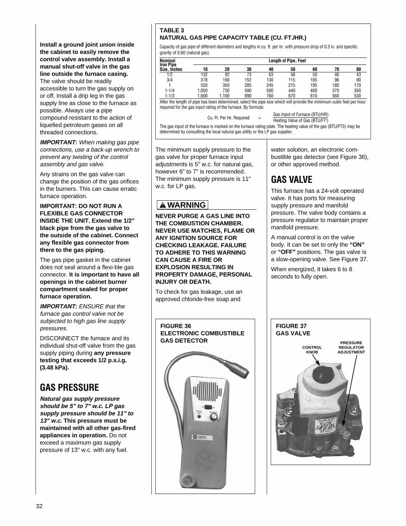
32
The minimum supply pressure to thegas valve for proper furnace inputadjustments is 5" w.c. for natural gas,however 6" to 7" is recommended.The minimum supply pressure is 11"w.c. for LP gas.
NEVER PURGE A GAS LINE INTOTHE COMBUSTION CHAMBER.NEVER USE MATCHES, FLAME ORANY IGNITION SOURCE FORCHECKING LEAKAGE. FAILURETO ADHERE TO THIS WARNINGCAN CAUSE A FIRE OREXPLOSION RESULTING INPROPERTY DAMAGE, PERSONALINJURY OR DEATH.
To check for gas leakage, use anapproved chloride-free soap and
Install a ground joint union insidethe cabinet to easily remove thecontrol valve assembly. Install amanual shut-off valve in the gasline outside the furnace casing.The valve should be readilyaccessible to turn the gas supply onor off. Install a drip leg in the gassupply line as close to the furnace aspossible. Always use a pipecompound resistant to the action ofliquefied petroleum gases on allthreaded connections.
IMPORTANT: When making gas pipeconnections, use a back-up wrench toprevent any twisting of the controlassembly and gas valve.
Any strains on the gas valve canchange the position of the gas orificesin the burners. This can cause erraticfurnace operation.
IMPORTANT: DO NOT RUN AFLEXIBLE GAS CONNECTORINSIDE THE UNIT. Extend the 1/2"black pipe from the gas valve tothe outside of the cabinet. Connectany flexible gas connector fromthere to the gas piping.
The gas pipe gasket in the cabinetdoes not seal around a flexi-ble gasconnector. It is important to have allopenings in the cabinet burnercompartment sealed for properfurnace operation.
IMPORTANT: ENSURE that thefurnace gas control valve not besubjected to high gas line supplypressures.
DISCONNECT the furnace and itsindividual shut-off valve from the gassupply piping during any pressuretesting that exceeds 1/2 p.s.i.g.(3.48 kPa).
GAS PRESSURENatural gas supply pressureshould be 5" to 7" w.c. LP gassupply pressure should be 11" to13" w.c. This pressure must bemaintained with all other gas-firedappliances in operation. Do notexceed a maximum gas supplypressure of 13" w.c. with any fuel.
! WARNING
FIGURE 36ELECTRONIC COMBUSTIBLEGAS DETECTOR
FIGURE 37GAS VALVE
PRESSURECONTROL REGULATOR
KNOB ADJUSTMENT
TABLE 3NATURAL GAS PIPE CAPACITY TABLE (CU. FT./HR.)Capacity of gas pipe of different diameters and lengths in cu. ft. per hr. with pressure drop of 0.3 in. and specificgravity of 0.60 (natural gas).
Nominal Length of Pipe, FeetIron PipeSize, Inches 10 20 30 40 50 60 70 80
1/2 132 92 73 63 56 50 46 433/4 278 190 152 130 115 105 96 901 520 350 285 245 215 195 180 170
1-1/4 1,050 730 590 500 440 400 370 3501-1/2 1,600 1,100 890 760 670 610 560 530
After the length of pipe has been determined, select the pipe size which will provide the minimum cubic feet per hourrequired for the gas input rating of the furnace. By formula:
Gas Input of Furnace (BTU/HR)Cu. Ft. Per Hr. Required = Heating Value of Gas (BTU/FT3)
The gas input of the furnace is marked on the furnace rating plate. The heating value of the gas (BTU/FT3) may bedetermined by consulting the local natural gas utility or the LP gas supplier.
water solution, an electronic com-bustible gas detector (see Figure 36),or other approved method.
GAS VALVEThis furnace has a 24-volt operatedvalve. It has ports for measuringsupply pressure and manifoldpressure. The valve body contains apressure regulator to maintain propermanifold pressure.
A manual control is on the valvebody. It can be set to only the “ON”or “OFF” positions. The gas valve isa slow-opening valve. See Figure 37.
When energized, it takes 6 to 8seconds to fully open.

33
LP CONVERSIONThe valve can be converted to useliquified petroleum (LP) gas byreplacing the pressure regulatorspring with the conversion kit spring.This LP kit spring allows the regulatorto maintain the proper manifoldpressure for LP gas. The correctburner LP orifices are included inthe kit. See Figure 38.
NOTE: Order the correct LPconversion kit from the furnacemanufacturer. Furnace conversionto LP gas must be performed by aqualified installer, service agencyor the gas supplier.
To change orifice spuds for eitherconversion to LP or for elevation:
1. Shut off the manual main gasvalve and remove the gasmanifold.
2. Replace the orifice spuds.
3. Reassemble in reverse order.
Consult the following table if there isany question concerning orificesizing.
ORIFICE SIZES
US 0 - 7999 FT. 8000 FT. & ABOVE
Natural Gas #50 #51
LP Gas 1.15 mm 1.10 mm
CANADIAN 0 - 2000 FT. 2001-4500 FT.
Natural Gas #50 #50
LP Gas 1.15 mm 1.15 mm
4. Turn the gas supply back on andcheck for proper operation andmanifold pressure. See Figures39, 40 and 41.
5. Attach the notice label alertingthe next service technician thatthe furnace has been convertedto LP gas.
NOx MODELSIMPORTANT: NOx inserts are notrequired when operating thisfurnace on LP gas.
When converting furnaces equippedwith NOx inserts to LP gas, removethe NOx insert assemblies. Steps forremoval are listed below:
1. Turn off all electrical power andthe gas supply to the furnace.
2. Remove the burner door from thefurnace.
3. Remove the igniter assembly –handle with care.
4. Remove the two screwsattaching the NOx insert retainerbrackets to the center panel. Pullthe retainer rod.
5. Put the two screws back into theholes in the center panel.
FIGURE 38LP KIT CONTENTS
FIGURE 39HOSE CONNECTION TO LINE PRESSURE TAP
6. Re-install the igniter and burnerassemblies.
7. Replace burner door.
8. Turn on electrical power and gassupply to the unit.

34
TABLE 4LP GAS PIPE CAPACITY TABLE (CU. FT./HR.)Maximum capacity of pipe in thousands of BTU per hour of undiluted liquefied petroleum gases (at 11 inches watercolumn inlet pressure).(Based on a Pressure Drop of 0.5 Inch Water Column)
Nominal Length of Pipe, FeetIron PipeSize, Inches 10 20 30 40 50 60 70 80 90 100 125 150
1/2 275 189 152 129 114 103 96 89 83 78 69 633/4 567 393 315 267 237 217 196 182 173 162 146 1321 1,071 732 590 504 448 409 378 346 322 307 275 252
1-1/4 2,205 1,496 1,212 1,039 913 834 771 724 677 630 567 5111-1/2 3,307 2,299 1,858 1,559 1,417 1,275 1,181 1,086 1,023 976 866 787
2 6,221 4,331 3,465 2,992 2,646 2,394 2,205 2,047 1,921 1,811 1,606 1,496
Example (LP): Input BTU requirement of unit, 150,000Equivalent length of pipe, 60 ft. = 3/4" IPS required.
SETTING GAS PRESSUREThe maximum gas supply pressureto the furnace should be 7" w.c.natural gas, or 13" w.c. LP gas. Theminimum supply gas pressure to thegas valve should be 5" w.c. naturalgas or 11" w.c. LP gas. A properlycalibrated U-Tube manometer isrequired for accurate gas pressuremeasurements.
Supply Gas Pressure Measure-ment. A line pressure tap is on theinput side of the gas valve. SeeFigure 39.
1. With gas shut off to the furnaceat the manual gas valve outsidethe unit, remove the inputpressure tap plug.
2. Connect a U-Tube manometer tothe pressure tap.
3. Turn on the gas supply andoperate the furnace and all othergas-fired units on the same gasline as the furnace.
4. Note or adjust the line gaspressure to give:
A. 5" - 7" w.c. for natural gas.
B. 11" - 13" w.c. for LP gas.
5. Shut off the gas at the manualgas valve and remove theU-Tube manometer.
6. Replace the pressure tap plugbefore turning on the gas.
If the supply gas line pressure isabove these ranges, install an in-linegas regulator to the furnace fornatural gas units. With LP gas, have
FIGURE 40MANIFOLD PLUG LOCATION
the LP supplier reduce the linepressure at the regulator.
If supply gas line pressure is belowthese ranges, either remove anyrestrictions in the gas supply piping orenlarge the gas pipe. See Tables 3and 4. With LP gas, have the LPsupplier adjust the line pressure atthe regulator.
Manifold Gas PressureMeasurement. Natural gasmanifold pressure should be 3.5"w.c. LP gas manifold pressureshould be 10.0" w.c. Only smallvariations in gas pressure should bemade by adjusting the pressureregulator.
1. With the gas to the unit shut offat the manual gas valve, removethe pressure tap plug in the gasmanifold. See Figure 40.
2. Connect a U-Tube manometer tothis pressure tap. See Figure 41.
3. Turn on the gas supply andoperate the furnace.
4. Note or adjust the manifold gaspressure to give:
A. 3.5" w.c. for natural gas.
B. 10.0" w.c. for LP gas.
5. To adjust the pressure regulator,remove the regulator cap.
6. Turn the adjustment screwclockwise to increase pressure,or counterclockwise to decreasepressure.
7. Securely replace the regulatorcap.
8. Shut off gas at the manual gasvalve and remove the U-Tubemanometer.
9. Replace the manifold pressuretap plug before turning onthe gas.
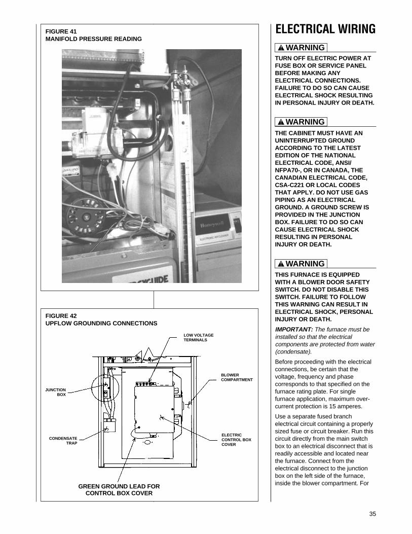
35
FIGURE 42UPFLOW GROUNDING CONNECTIONS
ELECTRICAL WIRING
TURN OFF ELECTRIC POWER ATFUSE BOX OR SERVICE PANELBEFORE MAKING ANYELECTRICAL CONNECTIONS.FAILURE TO DO SO CAN CAUSEELECTRICAL SHOCK RESULTINGIN PERSONAL INJURY OR DEATH.
THE CABINET MUST HAVE ANUNINTERRUPTED GROUNDACCORDING TO THE LATESTEDITION OF THE NATIONALELECTRICAL CODE, ANSI/NFPA70-, OR IN CANADA, THECANADIAN ELECTRICAL CODE,CSA-C221 OR LOCAL CODESTHAT APPLY. DO NOT USE GASPIPING AS AN ELECTRICALGROUND. A GROUND SCREW ISPROVIDED IN THE JUNCTIONBOX. FAILURE TO DO SO CANCAUSE ELECTRICAL SHOCKRESULTING IN PERSONALINJURY OR DEATH.
THIS FURNACE IS EQUIPPEDWITH A BLOWER DOOR SAFETYSWITCH. DO NOT DISABLE THISSWITCH. FAILURE TO FOLLOWTHIS WARNING CAN RESULT INELECTRICAL SHOCK, PERSONALINJURY OR DEATH.
IMPORTANT: The furnace must beinstalled so that the electricalcomponents are protected from water(condensate).
Before proceeding with the electricalconnections, be certain that thevoltage, frequency and phasecorresponds to that specified on thefurnace rating plate. For singlefurnace application, maximum over-current protection is 15 amperes.
Use a separate fused branchelectrical circuit containing a properlysized fuse or circuit breaker. Run thiscircuit directly from the main switchbox to an electrical disconnect that isreadily accessible and located nearthe furnace. Connect from theelectrical disconnect to the junctionbox on the left side of the furnace,inside the blower compartment. For
FIGURE 41MANIFOLD PRESSURE READING
! WARNING
! WARNING
! WARNING
JUNCTIONBOX
CONDENSATETRAP
GREEN GROUND LEAD FORCONTROL BOX COVER
ELECTRICCONTROL BOXCOVER
BLOWERCOMPARTMENT
LOW VOLTAGETERMINALS
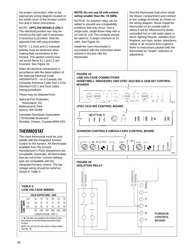
36
the proper connection, refer to theappropriate wiring diagram located onthe inside cover of the furnace controlbox and in these instructions.
NOTE: UPFLOW MODELS ONLYThe electrical junction box may bemoved to the right side if necessary.A knockout is provided. Seal theopposite hole with plug provided.
NOTE: L1 (hot) and L2 (neutral)polarity must be observed whenmaking field connections to thefurnace. The ignition control maynot sense flame if L1 and L2 arereversed. See Figure 43.
Make all electrical connections inaccordance with the latest edition ofthe National Electrical CodeANSI/NFPA70 – or in Canada, theCanadian Electrical Code Part 1-CSAStandard C22.1 and local codeshaving jurisdiction.
These may be obtained from:
National Fire ProtectionAssociation, Inc.
Batterymarch ParkQuincy, MA 02269
Canadian Standards Association178 Rexdale BoulevardRexdale, Ontario, Canada M9W 1R3
THERMOSTATThe room thermostat must be com-patible with the integrated furnacecontrol on the furnace. All thermostatsavailable from the furnacemanufacturer’s Parts Department areacceptable. Generally, all thermostatsthat are not of the “current robbing”type are compatible with theintegrated furnace control. The lowvoltage wiring should be sized asshown in Table 5.
FIGURE 44ISOLATION RELAY
TABLE 5LOW VOLTAGE WIRING
SOLID COPPER WIRE - AWG
3.0 16 14 12 10 10 10
2.5 16 14 12 12 10 10
2.0 18 16 14 12 12 10
50 100 150 200 250 300
LENGTH OF RUN - FEET ➀
➀ ➤ The total wire length is the distance fromthe furnace to the thermostat and back to thefurnace.NOTE: Do not use 24 volt control wiring smallerthan No. 18.
THER
MOS
TAT
LOAD
- AM
PS
FIGURE 43LINE VOLTAGE CONNECTIONSHONEYWELL S9201E2001 AND UTEC 1012-920 & 1028-927 CONTROLBOARDS
UTEC 1012-925 CONTROL BOARD
JOHNSON CONTROLS G961DAJ-2401 CONTROL BOARD
FURNACECONTROLBOARD
TO
TH
ER
MO
STA
T
“W”
TE
RM
INA
L
TO
TH
ER
MO
STA
T
“R”
TE
RM
INA
L
YG
RW
CT
WIN
NOTE: Do not use 24 volt controlwiring smaller than No. 18 AWG.
NOTICE: An isolation relay can beadded to prevent any compatibilityproblems that may occur. Use asingle-pole, single-throw relay with a24-volt AC coil. The contacts shouldbe rated for .5 amps minimum at 24volts. See Figure 44.
Install the room thermostat inaccordance with the instruction sheetpacked in the box with thethermostat.
Run the thermostat lead wires insidethe blower compartment and connectto low voltage terminals as shown onthe wiring diagram. Never install thethermostat on an outside wall orwhere it will be influenced by drafts,concealed hot or cold water pipes orducts, lighting fixtures, radiation fromfireplace, sun rays, lamps, televisions,radios or air streams from registers.Refer to instructions packed with thethermostat for “heater” selection oradjustment.
I334
I677
37
FIELD-INSTALLEDOPTION ACCESSORIESELECTRONIC AIR CLEANERLine voltage power can be suppliedfrom the screw terminal “EAC” and aline voltage neutral screw terminal onthe control board. This will power theelectronic air cleaner whenever thecirculating air blower is in operation.
HUMIDIFIERLine voltage power can be suppliedfrom screw terminal “HUM” to a linevoltage neutral screw terminal on thecontrol board. This will power thehumidifier whenever the burner ison and the circulating air blower isoperating in the heating mode.NOTE: Maximum current – 1.0 ampsfor each option.
HIGH ALTITUDE KITModels installed at altitudes of 5,000feet and above require a pressureswitch change. These may beordered under Option Code No. 278.Models with this option code will havethe additional pressure switch andburner orifice packed with thefurnace. The installer should replacethe induced draft blower pressureswitch installed on the furnace withthe new pressure switch. The burnerorifices should also be changed whenrequired (See Table Below). Thefollowing high altitude kits are alsoavailable:
Kit No: RXGY-F04 – set point – 0.70" w.c.
RXGY-F05 – set point – 0.60" w.c.
RXGY-F06 – set point – 1.11" w.c.
RXGY-F07 – set point – 0.95" w.c.
The following is a list of furnace in-puts and required pressure switches:
INPUT KIT NO. SET POINT MAKE POINT
45,000 RXGY-F06 1.11" w.c. 1.29" w.c.
60,000 RXGY-F06 1.11" w.c. 1.29" w.c.
75,000 RXGY-F07 0.95" w.c. 1.10" w.c..
90,000 RXGY-F06 1.11" w.c. 1.29" w.c..
105,000 RXGY-F04 0.70" w.c. 0.85" w.c.
120,000 RXGY-F05 0.60" w.c. 0.75" w.c.
ORIFICE SIZES
U.S. 0 - 7999 FT. 8000 FT. & ABOVE
Natural Gas #50 #51LP Gas 1.15 mm 1.10 mm
CANADA 0 - 2000 FT. 2001 TO 4500
Natural Gas #50 #50LP Gas 1.15 mm 1.15 mm
NOTICE: DO NOT make any attemptto rerate the furnace by changing gasorifices or the gas pressure. Allow thenatural derate of the gas to occur.
The natural derate is approximately1.8% per 1000 feet.No orifice sizing or other derateprocedures are necessary unless thenatural gas exceeds 1075 BTU/cu. ft.at sea level or the LP gas exceeds2500 BTU/cu. ft. at sea level. If theheating values exceed these levels,consult the manufacturer for thederate procedures.
FURNACE TWINNINGINSTALLATIONSTwinning operation of two furnaces,installed side-by-side, connected by acommon duct system with mainpower supplied by the same source,and controlled by a commonthermostat can be done with theHoneywell S9201E2001, UTEC 1012-920 or 1028-927 and JohnsonControls G961DAJ-2401 integratedcontrol boards.IMPORTANT: TWINNING OF (-)GRJ-AND (-)GTJ- UNITS REQUIRES ANACCESSORY TWINNING KIT.REFER TO THE SPECIFICATIONSHEET FOR PROPER KIT. DO NOTATTEMPT TO TWIN THESEMODELS BY USING THEINSTRUCTIONS BELOW.It should be noted that both blowerswill run simultaneously when there isa call for heating, cooling or fan.The “OK” LED will flash if twinning isnot set up properly.
HONEYWELL S9201E2001CONTROL BOARD1. Single Stage Operation
(See Figure 45)a. Control board “ONE” is
connected to the thermostat.b. Remove the jumper between
the “XMIT” and “RCV”terminals.
c. Connect wire from “XMIT”terminal of board “ONE” to“RCV” terminal of board“TWO.”
d. Connect wire from “RCV”terminal of board “ONE” to“XMIT” terminal of board“TWO.”
e. Connect wire between thegrounds.
f. Connect wire between the two“W” thermostat terminals.
2. Two Stage Operation(See Figure 46)a. Repeat steps a, b, c, d and e
above.b. Connect “W1” of thermostat to
“W” on control board “ONE”.c. Connect “W2” of thermostat to
“W” on control board “TWO”.
UTEC 1012-920 & 1028-927CONTROL BOARDS1. Single Stage Operation
(See Figure 47)a. Control board “ONE” is on
furnace connected to thethermostat.
b. The 24 VAC supply to bothcontrol boards must be inphase with each other.
c. Connect the “C,” “W” and“TWIN” terminals tocounterparts on each control.
d. Both control boards must haveswitch #3 in the “ON” position.
e. Control board “ONE” musthave the switch #4 in the “1st”position. The other controlboard must have switch #4 inthe “ON” position for singlestage heat operation. NOTE:The 1028-927 control boardhas no 4th, 1st-2nd switch,Staging is determined through“W” terminal connections only.
2. Two Stage Operation(See Figure 48)a. Follow above instructions:
Switch #4 on control board“TWO” must be in “2nd”position. Control board “TWO”must be the slave (notconnected to the thermostat)in two-stage operation.
b. Connect “W2” on thermostatto “W” on control board“TWO”.
Johnson Controls G961DAJ-24011. Single Stage Operation
(See Figure 49)a. Control board “ONE” is on the
furnace connected to thethermostat.
b. The 24 VAC supply to bothcontrol boards must be inphase with each other.
c. Connect the “C” “W” and“TWIN” terminals to counter-parts on each control.
d. Both control boards must haveswitch #1 in the “ON” position.
e. Control board “ONE” musthave switch #2 in the “ON”position. The other controlboard must have switch #2 inthe “OFF” position for singlestage heat.
2. Two Stage Operation(See Figure 50)a. Follow above instructions
except connect “W2” on thethermostat to “W” on controlboard “TWO.”
b. Control board “TWO” must bethe slave (not connected tothe thermostat) in two-stageoperation.
ACCESSORIES

38
FIGURE 45HONEYWELL NO. S9201E2001 CONTROL BOARDTWINNING CONNECTION SINGLE STAGE OPERATION
I400
39
FIGURE 46HONEYWELL NO. S9201E2001 CONTROL BOARDTWINNING CONNECTION TWO STAGE OPERATION
I401

40
FIGURE 47UTEC NO. 1012-920 & 1028-927 CONTROL BOARDTWINNING CONNECTION SINGLE STAGE OPERATION
I398

41
FIGURE 48UTEC NO. 1012-920 & 1028-927 CONTROL BOARDTWINNING CONNECTION TWO STAGE OPERATION
I398
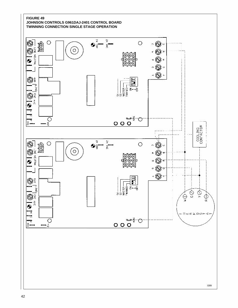
42
FIGURE 49JOHNSON CONTROLS G961DAJ-2401 CONTROL BOARDTWINNING CONNECTION SINGLE STAGE OPERATION
I399

43
FIGURE 50JOHNSON CONTROLS G961DAJ-2401 CONTROL BOARDTWINNING CONNECTION TWO STAGE OPERATION
I399
44
START-UP PROCEDURESThis furnace is equipped with a siliconcarbide hot surface ignition (HSI) device.Each time the room thermostat calls forheat, the HSI lights the main burnersdirectly See the lighting instructions onthe furnace.
TO START THE FURNACE1. Remove the burner compartment
control access door.2. IMPORTANT: Be sure that the
manual gas control has been in the“OFF” position for at least fiveminutes. Do not attempt to manuallylight the main burners.
3. Turn off the furnace electrical powerand set the room thermostat to itslowest setting.
4. Turn the gas control knob to the“ON” position.
5. Replace the burner compartmentcontrol access door.
6. Turn on the furnace electrical power.7. Set the room thermostat to a point
above room temperature to light themain burners.
8. After the burners are lit, set the roomthermostat to a desired temperature.
TO SHUT DOWNTHE FURNACE1. Set the room thermostat to its lowest
setting.2. Remove the burner compartment
control access door.3. Shut off the gas to the main burners
by turning the gas control knob tothe “OFF” position. See Figure 36.
SHOULD OVERHEATING OCCUROR THE GAS SUPPLY FAIL TOSHUT OFF, CLOSE THE MANUALGAS VALVE FOR THE APPLIANCEBEFORE SHUTTING OFF THEELECTRICAL SUPPLY. FAILURE TODO SO CAN CAUSE AN EXPLOSIONOR FIRE RESULTING IN PROPERTYDAMAGE, PERSONAL INJURY ORDEATH.
SEQUENCE OF OPERATIONHoneywell or UTEC IntegratedControls with Hot Surface Ignition.1. Each time the thermostat contacts
close, the induced draft blower(inducer) begins a prepurge cycle.
2. The air proving negative pressureswitch(es) closes.
3. 30 seconds after the pressureswitch(es) close, the hot surfaceigniter heats for 30 seconds to fulltemperature. The induced draftblower operates for the completeheating cycle.
4. After the 30-second igniter warm up,the gas valve opens for a9-second trial for ignition.
5. The igniter lights the gas burnersand stays energized for the first 8seconds after the gas valveopens.
6. 8 seconds after the gas valve opensthe remote flame sensor mustprove flame ignition for onesecond using the process of flamerectification. If the burners don’t light,the system goes through anotherignition sequence. It does this up tofour times.
7. The main blower startsapproximately 20 seconds after theburners ignite.
8. When the thermostat cycle ends, thegas valve closes, the burners goout, the induced draft blower stopsafter a 5-second post-purge, andthe negative pressure switch(es)open.
9. The main blower continues untiltimed off by the setting on theintegrated furnace control board.
Sequence if the system doesn’t lightor doesn’t sense flame:1. On a call for heat, the control runs
the inducer for 30 seconds toprepurge.
2. After the 30-second prepurge, thehot surface igniter heats for 30seconds. The inducer continues torun.
3. After the 30-second igniter warm up,the gas valve opens for a9-second trial for ignition. Theinducer continues and the igniterstays energized.
4. If flame is not sensed during theninth second after the gas valveopens, the gas valve closes, and theigniter de-energizes.
5. After a 30 second inter-purge, theigniter heats for 30 seconds. After30 seconds, the gas valve opens for9 seconds. If no flame is sensed, itcloses the gas valve, the igniter de-energizes. Both the inducer andmain blower operate for 180seconds.
6. It retries up to four times. At the endof the last try, the inducer stopsimmediately. The system is in“soft” lock out.
7. The above sequence will repeatafter a one hour delay. It willcontinue repeating until ignition issuccessful or the call for heat isterminated.
8. To reset the lock out, make andbreak power either at thethermostat or at the unitdisconnect switch for 5 to 10seconds. It then goes throughanother set of trials for ignition.
UTEC or Johnson Controls DirectSpark Ignition1. Each time the thermostat contacts
close, the induced draft blower(inducer) begins a prepurge cycle.
2. The air proving negative pressureswitch(es) closes.
3. 30 seconds after the pressureswitch(es) close, the sparkigniter energizes. The induceddraft blower operates for thecomplete heating cycle.
4. After the spark igniter energizes,the gas valve opens for a 8second trial for ignition.
5. The igniter lights the gas burners.6. After the gas valve opens the
flame sensor must prove flameignition for one second using theprocess of flame rectification. If theburners don’t light, the systemgoes through another ignitionsequence. It does this up to fourtimes.
7. The main blower starts 20 secondsafter the burners ignite.
8. When the thermostat cycle ends,the gas valve closes, the burnersgo out, the induced draft blowerstops after a 5-second post-purge, and the negative pressureswitch(es) open.
9. The main blower continues untiltimed off by the setting on theintegrated furnace control board.
Sequence if the system doesn’tlight or doesn’t sense flame:1. On a call for heat, the control runs
the inducer for 30 seconds to pre-purge.
2. After the 30-second pre-purge, thespark igniter energizes. Theinducer continues to run.
3. After the spark igniter energizes,the gas valve opens for a 8-second trial for ignition. Theinducer continues and the igniterstays energized.
4. If flame is not sensed within 8seconds after the gas valve opens,the gas valve closes, and theigniter de-energizes.
5. After a 30-second inter-purge, theigniter is energized, the gas valveopens for 8 seconds. If no flame issensed, it closes the gas valve, theigniter de-energizes. Both themain blower and the induceroperate for 180 seconds beforethe next ignition trial.
6. It retries up to four times. At theend of the last try, the inducerstops. The system is in “soft”lockout.
7. The above sequence will repeatafter a one hour delay. It willcontinue repeating until ignition issuccessful or the call for heat isterminated.
8. To reset the lock out, make andbreak power either at thethermostat or at the unitdisconnect switch for 5 to 10seconds. It then goes throughanother set of trials for ignition.
! WARNING

45
ADJUSTING OR CHECKINGFURNACE INPUTThe maximum gas supply pressureto the furnace should be 7" w.c.for natural gas. The minimum gassupply pressure for purposes of inputadjustment to the furnace should be5" w.c.
A properly calibrated magnehelicgauge or manometer is required foraccurate gas pressure readings.
The manifold pressure should be setat 3.5" w.c. for natural gas. Onlysmall variations in the gas flowshould be made by means of thepressure regulator adjustment. In nocase should the final manifoldpressure vary more than plus orminus 0.3" w.c. from the above-specified pressures. To adjust thepressure regulator, remove theregulator cap and turn the adjustmentscrew clockwise to increase pressureor counterclockwise to decreasepressure. Then replace the regulatorcap securely. Any necessary majorchanges in the gas flow rate shouldbe made by changing the size of theburner orifices.
To change orifice spuds, shut off themanual gas valve and remove thegas manifold. On LP gas furnaces,the LP gas supply pressure must beset between 11" and 14" w.c. bymeans of the tank or branch supplyregulators. The furnace manifoldpressure should be set at 10" w.c. atthe gas control valve. For elevationsup to 2,000 feet, rating plate inputratings apply. For high altitudes(elevations over 2,000 ft.), seeconversion kit index 92-21519-XX forderating and orifice spud sizes.
Checking furnace input is importantto prevent over firing beyond itsdesign-rated input. NEVER SETINPUT ABOVE THAT SHOWN ONTHE RATING PLATE. Use thefollowing table or formula todetermine input rate. Start thefurnace and measure the timerequired to burn one cubic foot ofgas. Prior to checking the furnaceinput, make certain that all other gasappliances are shut off, with theexception of pilot burners. Time themeter with only the furnace inoperation.
SETTING INPUT RATEThe furnace is shipped from thefactory with #50 orifices. They aresized for natural gas having a heatingvalue of 1075 BTU/cu. ft. and aspecific gravity of .60.
Since heating values vary geo-graphically, the manifold pressureand/or gas orifice size may need tobe changed to adjust the furnace toits nameplate input. Consult the localgas utility to obtain the yearlyaverage heating value and orificesize required to fire each individualburner at 15,000 BTU/HR.
TABLE 6METER TIME
METER TIME IN MINUTES AND SECONDS FOR NORMAL INPUT RATING OF FURNACESEQUIPPED FOR NATURAL OR LP GAS
HEATING VALUE OF GAS BTU PER CU. FT.METER
900 1000 1040 1100 2500 (LP)INPUT SIZE
BTU/HR CU. FT. MIN. SEC. MIN. SEC. MIN. SEC. MIN. SEC. MIN. SEC.
ONE 1 12 1 20 1 23 1 28 3 20
45,000 TEN 12 0 13 20 13 50 14 40 33 20
ONE 0 54 1 0 1 3 1 6 2 30
60,000 TEN 9 0 10 0 10 24 11 0 25 0
ONE 0 44 0 48 0 50 0 53 2 0
75,000 TEN 7 12 8 0 8 19 8 48 20 0
ONE 0 36 0 40 0 42 0 44 1 40
90,000 TEN 6 0 6 40 7 0 7 20 16 40
ONE 0 31 0 34 0 36 0 38 1 26
105,000 TEN 5 10 5 40 6 0 6 20 14 20
ONE 0 27 0 30 0 31 0 33 1 15
120,000 TEN 4 30 5 0 5 10 5 30 12 30
Heating Value of Gas (BTU/FT3) x 3600Formula: Input BTU/HR =
Time in Seconds (for 1 cu. ft.) of Gas
46
AIR FLOWThe importance of proper air flowover the heat exchanger cannot beover emphasized. One of the mostcommon causes of heat exchangerfailure is overheating due to low airflow. An air flow table is located insidethe blower door.
TEMPERATURE RISE CHECK
To determine if the air flow is correct,make a temperature rise check.
1. Insert a thermometer in thesupply air duct as close to thefurnace as possible yet out of adirect line from the heatexchanger. See Figure 51.
2. Insert a thermometer in thereturn air duct as close to thefurnace as possible.
3. Operate the furnace.
4. When the thermometer in thesupply air duct stops rising(approximately five minutes),subtract the return airtemperature from the supply airtemperature. The difference isthe temperature rise.
5. Compare the measuredtemperature rise to the approvedtemperature rise range listed onthe furnace name plate. SeeFigure 52.
If the measured temperature rise isabove the approved range, the airflow is too low. More air must bemoved by speeding up the blower,by removing restrictions in the ductsystem, or by adding more supply orreturn air duct. If the measuredtemperature rise is below theapproved range, the air flow is toomuch. Use lower speed tap on themulti-speed blower.
Ideally the measured temperature riseshould be in the middle of the range.
FIGURE 51TEMPERATURE RISE MEASUREMENT
FIGURE 52FURNACE NAME PLATE

47
TABLE 7
90 PLUS AIR FLOW PERFORMANCECFM @ ESPMODEL BLOWER/ SPEED
MOTOR HP .1 .2 .3 .4 .5 .6 .7
RGRA-04 11 x 7 / 1/2 LOW 805 780 760 720 685 645 605*M-LO 920 885 850 810 775 730 690M-HI 1140 1110 1085 1045 1010 950 890HIGH 1360 1320 1280 1235 1195 1140 1080
RGTA-04 11 x 7 / 1/2 LOW 820 790 760 725 690 650 610*M-LO 930 890 850 815 785 750 720M-HI 1150 1120 1090 1045 1002 950 900HIGH 1414 1365 1320 1270 1220 1165 1115
RGRA-06 11 x 7 / 1/2 LOW 770 740 710 675 645 605 570*M-LO 880 845 815 790 760 715 670M-HI 1060 1025 990 960 925 880 835HIGH 1260 1215 1175 1135 1100 1040 985
RGTA-06 11 x 7 / 1/2 LOW 795 760 730 695 660 615 570*M-LO 910 885 860 815 770 725 680M-HI 1115 1080 1045 1005 965 920 875HIGH 1365 1315 1270 1225 1180 1125 1070
RGRA-07 11 X 7 / 1/2 LOW 780 745 710 675 640 595 555M-LO 880 850 825 785 750 702 655*M-HI 1090 1050 1010 970 925 875 825HIGH 1300 1255 1210 1160 1110 1055 1005
RGTA-07 11 X 7 / 1/2 LOW 780 750 720 675 635 595 555M-LO 890 860 835 790 750 705 660*M-HI 1100 1060 1025 980 940 890 845HIGH 1340 1295 1250 1200 1150 1090 1025
RGRA-07 12 X 7 1/2 / 3/4 LOW 1105 1095 1080 1050 1030 1010 990M-LO 1290 1275 1260 1220 1195 1170 1140M-HI 1480 1435 1415 1390 1370 1300 1255HIGH 1705 1665 1615 1570 1540 1475 1400
RGTA-07 12 X 7 1/2 / 3/4 LOW 1185 1160 1140 1115 1095 1065 1040M-LO 1405 1375 1350 1310 1270 1235 1195M-HI 1595 1560 1525 1480 1440 1380 1325HIGH 1835 1780 1730 1675 1625 1555 1480
RGRA-09 12 X 11 / 3/4 LOW 1235 1210 1185 1150 1120 1075 1035*M-LO 1490 1465 1440 1405 1375 1315 1255M-HI 1720 1670 1620 1600 1580 1520 1460HIGH 2100 2050 2000 1955 1910 1825 1745
RGTA-09 12 X 11 / 3/4 LOW 1155 1125 1100 1080 1060 1000 940*M-LO 1420 1400 1380 1365 1350 1260 1175M-HI 1605 1575 1550 1560 1570 1480 1390HIGH 2005 1965 1930 1890 1850 1765 1680
RGRA-10 12 X 11 / 3/4 LOW 1230 1205 1180 1155 1130 1090 1050*M-LO 1490 1445 1405 1375 1350 1295 1240M-HI 1710 1665 1620 1580 1540 1475 1410HIGH 2010 1955 1900 1855 1810 1710 1610
RGTA-10 12 X 11 / 3/4 LOW 1180 1150 1120 1100 1080 1025 970*M-LO 1460 1425 1390 1375 1360 1280 1200M-HI 1680 1645 1615 1585 1560 1490 1420HIGH 2055 2000 1940 1880 1820 1745 1675
RGRA-12 11 X 10 / 3/4 LOW 1320 1305 1290 1260 1230 1185 1140*M-LO 1610 1580 1555 1515 1475 1415 1355M-HI 1870 1820 1775 1715 1660 1590 1520HIGH 2115 2050 1990 1945 1900 1795 1690
RGTA-12 11 X 10 / 3/4 LOW 1285 1250 1215 1235 1260 1230 1200*M-LO 1590 1565 1540 1505 1475 1425 1375M-HI 1840 1820 1800 1750 1700 1645 1590HIGH 2315 2250 2185 2110 2040 1965 1890
* Heating speed for cooling applicationsNOTE: Units tested with filters in place.
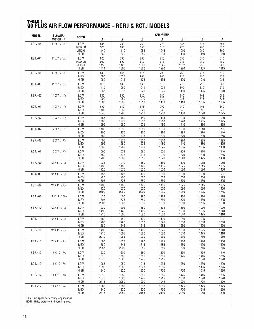
48
TABLE 890 PLUS AIR FLOW PERFORMANCE – RGRJ & RGTJ MODELS
CFM @ ESPMODEL BLOWER/ SPEEDMOTOR HP .1 .2 .3 .4 .5 .6 .7
RGRJ-04 11 x 7 / 1/2 LOW 805 780 760 720 685 645 605MED-LO 920 885 850 810 775 730 690MED-HI 1140 1110 1085 1045 1010 950 890HIGH 1360 1320 1280 1235 1195 1140 1080
RGTJ-04 11 x 7 / 1/2 LOW 820 790 760 725 690 650 610MED-LO 930 890 850 815 785 750 720MED-HI 1150 1120 1090 1045 1002 950 900HIGH 1414 1365 1320 1270 1220 1165 1115
RGRJ-06 11 x 7 / 1/2 LOW 880 845 815 790 760 715 670MED 1060 1025 990 960 925 880 835HIGH 1260 1215 1175 1135 1100 1040 985
RGTJ-06 11 x 7 / 1/2 LOW 910 885 860 815 770 725 680MED 1115 1080 1045 1005 965 920 875HIGH 1365 1315 1270 1225 1180 1125 1070
RGRJ-07 11 X 7 / 1/2 LOW 880 850 825 785 750 702 655MED 1090 1050 1010 970 925 875 825HIGH 1300 1255 1210 1160 1110 1055 1005
RGTJ-07 11 X 7 / 1/2 LOW 890 860 835 790 750 705 660MED 1100 1060 1025 980 940 890 845HIGH 1340 1295 1250 1200 1150 1090 1025
RGRJ-07 12 X 7 / 1/2 LOW 1185 1160 1140 1115 1095 1065 1040MED 1405 1375 1350 1310 1270 1235 1195HIGH 1595 1560 1525 1480 1440 1380 1325
RGTJ-07 12 X 7 / 1/2 LOW 1105 1095 1080 1050 1030 1010 990MED 1290 1275 1260 1220 1195 1170 1140HIGH 1480 1435 1415 1390 1370 1300 1255
RGRJ-07 12 X 7 / 3/4 LOW 1405 1375 1350 1310 1270 1235 1195MED 1595 1560 1525 1480 1440 1380 1325HIGH 1835 1780 1730 1675 1625 1555 1480
RGTJ-07 12 X 7 / 3/4 LOW 1290 1275 1260 1220 1195 1170 1140MED 1480 1435 1415 1390 1370 1300 1255HIGH 1705 1665 1615 1570 1540 1475 1400
RGRJ-09 12 X 11 / 1/2 LOW 1235 1210 1180 1150 1120 1075 1035MED 1490 1465 1445 1405 1375 1315 1255HIGH 1720 1670 1620 1600 1580 1520 1460
RGTJ-09 12 X 11 / 1/2 LOW 1155 1125 1100 1080 1060 1000 940MED 1420 1400 1380 1365 1350 1260 1175HIGH 1605 1575 1550 1560 1570 1480 1395
RGRJ-09 12 X 11 / 3/4 LOW 1490 1465 1445 1405 1375 1315 1255MED 1720 1670 1620 1600 1580 1520 1460HIGH 2100 2050 2000 1955 1910 1825 1745
RGTJ-09 12 X 11 / 3/24 LOW 1420 1400 1380 1365 1350 1260 1175MED 1605 1575 1550 1560 1570 1480 1395HIGH 2005 1965 1930 1890 1850 1765 1680
RGRJ-10 12 X 11 / 1/2 LOW 1230 1205 1180 1155 1130 1090 1050MED 1490 1445 1405 1375 1350 1295 1240HIGH 1710 1665 1620 1580 1540 1475 1410
RGTJ-10 12 X 11 / 1/2 LOW 1180 1150 1120 1100 1080 1025 970MED 1460 1425 1390 1375 1360 1280 1200HIGH 1680 1645 1615 1585 1560 1490 1420
RGRJ-10 12 X 11 / 3/4 LOW 1490 1445 1405 1375 1350 1295 1240MED 1710 1665 1620 1580 1540 1475 1410HIGH 2010 1955 1900 1855 1810 1710 1610
RGTJ-10 12 X 11 / 3/4 LOW 1460 1425 1390 1375 1360 1280 1200MED 1680 1645 1615 1585 1560 1490 1420HIGH 2055 2000 1940 1880 1820 1745 1675
RGRJ-12 11 X 10 / 1/2 LOW 1320 1305 1290 1260 1230 1185 1140MED 1610 1580 1555 1515 1475 1415 1355HIGH 1870 1820 1775 1715 1 1590 1520
RGTJ-12 11 X 10 / 1/2 LOW 1285 1250 1215 1235 1260 1230 1200MED 1590 1565 1540 1505 1 1425 1375HIGH 1840 1820 1800 1750 1700 1645 1590
RGRJ-12 11 X 10 / 3/4 LOW 1610 1580 1555 1515 1475 1415 1355MED 1870 1820 1775 1715 1660 1590 1520HIGH 2115 2050 1990 1945 1900 1795 1690
RGTJ-12 11 X 10 / 3/4 LOW 1590 1565 1540 1505 1475 1425 1375MED 1840 1820 1800 1750 1700 1645 1590HIGH 2315 2250 2185 2110 2040 1965 1890
* Heating speed for cooling applicationsNOTE: Units tested with filters in place.
49
SETTING BLOWERTIMINGSThe Honeywell and UTEC controlboards have four quick connectterminals for connecting the motorspeed leads. These are:
1. FAN SPEED — motor runs onthis speed when the thermostatis in the “FAN ON” position.
2. COOL — connect desiredcooling speed.
3. HEAT — connect desiredheating speed.
4. HEAT/COOL (not available onUTEC-925 control board) —connect desired speed whenheating and cooling speed arethe same.
IMPORTANT: Do not connect anymotor speeds to “HEAT” and “COOL”if you use the “HEAT/COOL” terminal.
5. If heating and continuous fanspeed are the same, “piggyback”jumper across “FAN” and “HEAT”terminals.
See Figures 53, 54, 55 and 56 forinstructions for setting the blower“OFF” timings.
If cooling speed and fan speed aredesired to be the same, this may beaccomplished by not connecting “Y”to the integrated furnace control.
If desired for cool, fan and heat to allbe the same speed, then “piggyback”jumper “H/C” to “FAN” and do notconnect “Y” to the integrated furnacecontrol. Do not connect anything to“H” or “C.”
GAS FURNACE (DIRECTDRIVE) INSTRUCTIONSFOR CHANGING BLOWERSPEED
DISCONNECT THE ELECTRICALSUPPLY TO THE FURNACEBEFORE ATTEMPTING TOCHANGE THE BLOWER SPEED.FAILURE TO DO SO CAN CAUSEELECTRICAL SHOCK RESULTINGIN PERSONAL INJURY OR DEATH.
The blower motor is wired for blowerspeeds required for normal operationas shown.
If additional blower speed taps areavailable (leads connected to “M1”and “M2” on the electronic control),speeds may be changed if necessaryto fit requirements of the particularinstallation. Reconnect the unusedmotor leads to “M1” or “M2.” Checkmotor lead color for speeddesignation.
Heating speeds should not bereduced where it could cause thefurnace air temperature to rise toexceed the maximum outlet airtemperature specified for the unit.
IMPORTANT: Always check airtemperature rise after changing theheating speed for any reason.
FIGURE 54JOHNSON CONTROLSG961DAJ-2401BLOWER OFF TIMINGS
FIGURE 55HONEYWELL E2001BLOWER OFF TIMINGS
OFF TIME SWITCH 3 SWITCH 4
90 SEC. ON ON
120 SEC. OFF ON
160 SEC. ON OFF
180 SEC. OFF OFF
OFF TIME SWITCH 1 SWITCH 2
90 SEC. ON OFF
120 SEC. OFF OFF
160 SEC. OFF ON
180 SEC. ON ON
! WARNINGTW
INN
ED
MA
ST
ER
SIN
GL
E1S
TNOTE: SWITCHES 1 & 2 ARE USEDFOR TWINNING APPLICATIONS.
ON
(TIMER ISRED BLOCKON BOARD)
I402
FIGURE 53UTEC -920 & -927BLOWER OFF TIMINGS
OFF TIME SWITCH 1 SWITCH 2
90 SEC. OFF ON
120 SEC. OFF OFF
160 SEC. ON OFF
180 SEC. ON ON
TW
IN2n
dS
ING
LE
1STNOTE: SWITCHES 3 & 4 ARE USED
FOR TWINNING APPLICATIONS.
ON
I402
I335
I402
FIGURE 56UTEC - 925BLOWER OFF TIMINGS
OFF TIME SWITCH 1 SWITCH 2
90 SEC. OFF ON
120 SEC. OFF OFF
160 SEC. ON OFF
180 SEC. ON ON
(TIMER ISRED BLOCKON BOARD)
I335
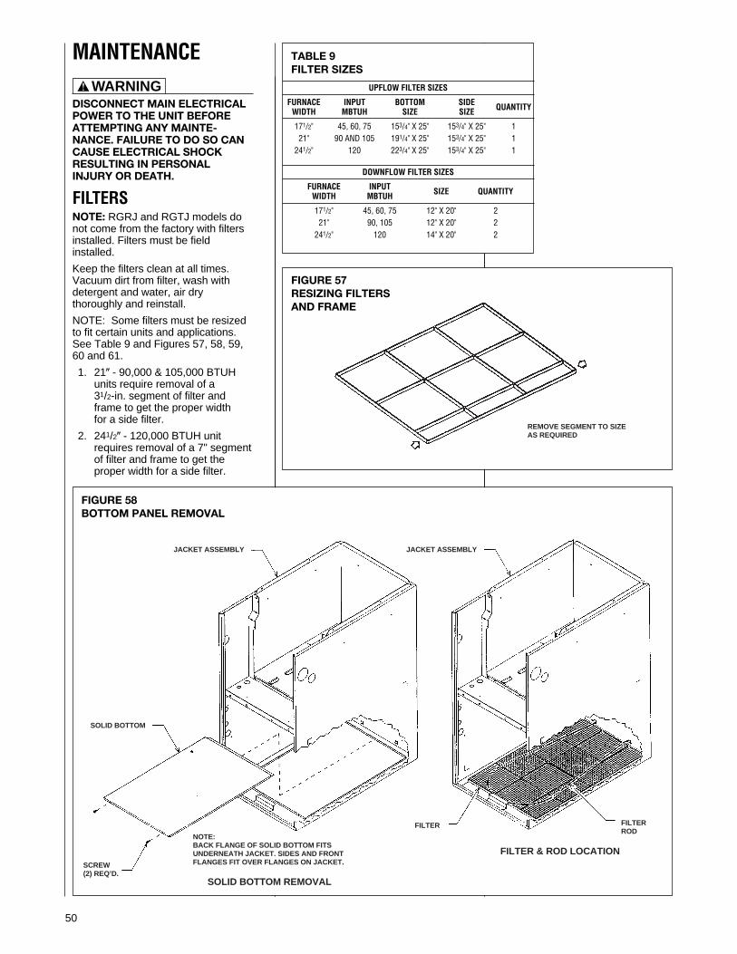
50
DISCONNECT MAIN ELECTRICALPOWER TO THE UNIT BEFOREATTEMPTING ANY MAINTE-NANCE. FAILURE TO DO SO CANCAUSE ELECTRICAL SHOCKRESULTING IN PERSONALINJURY OR DEATH.
FILTERSNOTE: RGRJ and RGTJ models donot come from the factory with filtersinstalled. Filters must be fieldinstalled.
Keep the filters clean at all times.Vacuum dirt from filter, wash withdetergent and water, air drythoroughly and reinstall.
NOTE: Some filters must be resizedto fit certain units and applications.See Table 9 and Figures 57, 58, 59,60 and 61.
1. 21( - 90,000 & 105,000 BTUHunits require removal of a31/2-in. segment of filter andframe to get the proper widthfor a side filter.
2. 241/2( - 120,000 BTUH unitrequires removal of a 7" segmentof filter and frame to get theproper width for a side filter.
! WARNING
TABLE 9FILTER SIZES
UPFLOW FILTER SIZES
FURNACE INPUT BOTTOM SIDE QUANTITYWIDTH MBTUH SIZE SIZE
171/2" 45, 60, 75 153/4" X 25" 153/4" X 25" 121" 90 AND 105 191/4" X 25" 153/4" X 25" 1
241/2" 120 223/4" X 25" 153/4" X 25" 1
DOWNFLOW FILTER SIZES
FURNACE INPUT SIZE QUANTITYWIDTH MBTUH
171/2" 45, 60, 75 12" X 20" 221" 90, 105 12" X 20" 2
241/2" 120 14" X 20" 2
FIGURE 57RESIZING FILTERSAND FRAME
MAINTENANCE
FIGURE 58BOTTOM PANEL REMOVAL
JACKET ASSEMBLY
SOLID BOTTOM
NOTE:BACK FLANGE OF SOLID BOTTOM FITSUNDERNEATH JACKET. SIDES AND FRONTFLANGES FIT OVER FLANGES ON JACKET.SCREW
(2) REQ’D.
JACKET ASSEMBLY
FILTER FILTERROD
SOLID BOTTOM REMOVAL
FILTER & ROD LOCATION
REMOVE SEGMENT TO SIZEAS REQUIRED
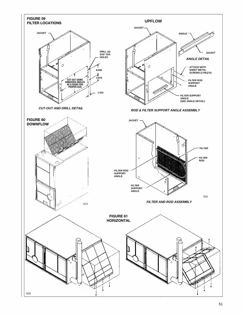
51
FIGURE 59FILTER LOCATIONS
FIGURE 60DOWNFLOW
FIGURE 61HORIZONTAL
JACKET
DRILL (2)3/16" DIA.HOLES
8.000
4.875
1.531
CUT-OUT USINGEMBOSSED ANGLES
AS A GUIDE FORPROPER SIZE
JACKET
JACKET
ANGLE
FILTER RODSUPPORTANGLE
FILTER SUPPORTANGLE(SEE ANGLE DETAIL)
ATTACH WITHSHEET METALSCREWS (2 REQ’D)
ANGLE DETAIL
CUT-OUT AND DRILL DETAILROD & FILTER SUPPORT ANGLE ASSEMBLY
FILTER AND ROD ASSEMBLY
FILTER RODSUPPORTANGLE
FILTERSUPPORTANGLE
FILTER
FILTER ROD
JACKET
I332
I413
UPFLOW
I528

52
HOLES IN THE VENT PIPE ORHEAT EXCHANGER CAN CAUSETOXIC FUMES TO ENTER THEHOME, RESULTING IN CARBONMONOXIDE POISONING ORDEATH. THE VENT PIPE OR HEATEXCHANGER MUST BEREPLACED IF THEY LEAK.
• IMPORTANT: It is recommendedthat at the beginning of the heatingseason, the flame sensor becleaned with steel wool by aqualified installer, service agency orthe gas supplier.
• IMPORTANT: It is recommendedthat at the beginning of the heatingseason, the condensate trap beinspected for debris or blockage. Ablocked condensate trap can causewater to back up into the primaryheat exchanger and lead tonuisance tripping of theovertemperature switches.
• IMPORTANT: It is recommendedthat at the beginning of the heatingseason, the condensate neutralizerif used be replaced by a qualifiedinstaller, service agency or the gassupplier.
• IMPORTANT: It is recommendedthat an annual inspection andcleaning of all furnace markings bemade to assure legibility. Attach areplacement marking, which can beobtained through the distributor, ifany are found to be illegible ormissing.
REPLACEMENT PARTSContact your local distributor for acomplete parts list. See enclosedsheet.
TROUBLESHOOTINGRefer to Figures 62, 63 and 64 fordetermining cause of unit problems.
WIRING DIAGRAMFigures 65, 66 and 67 are completewiring diagrams for the furnace andpower sources.
Do not operate the system forextended periods without filters.A portion of the dust entrained in theair may temporarily lodge in the airduct runs and at the supply registers.Any recirculated dust particles willbe heated and charred by contactwith the furnace heat exchanger.This residue will soil ceilings, walls,drapes, carpets and other householdarticles.
LUBRICATIONIMPORTANT: DO NOT attempt tolubricate the bearings on the blowermotor or the induced draft blowermotor. Addition of lubricants canreduce the motor life and void thewarranty.
The blower motor and induced draftblower motor are permanentlylubricated by the manufacturer and donot require further attention.
The blower motor and induced draftblower motor must be cleanedperiodically by a qualified installer,service agency, or the gas supplier toprevent the possibility of overheatingdue to an accumulation of dust anddirt on the windings or on the motorexterior. And, as suggestedelsewhere in these instructions, theair filters should be kept clean. Dirtyfilters can restrict airflow. The motordepends upon sufficient air flowingacross and through it to keep fromoverheating.
SYSTEM OPERATIONINFORMATIONAdvise The Customer
1. Keep the air filters clean. Theheating system will operatebetter, more efficiently and moreeconomically.
2. Arrange the furniture and drapesso that the supply air registersand the return air grilles areunobstructed.
3. Close doors and windows. Thiswill reduce the heating load onthe system.
4. Avoid excessive use of kitchenexhaust fans.
5. Do not permit the heat generatedby television, lamps or radios toinfluence the thermostatoperation.
6. Except for the mounting platform,keep all combustible articles 3feet from the furnace and ventsystem.
7. IMPORTANT: Replace allblower doors and compartmentcovers after servicing thefurnace. Do not operate the unitwithout all panels and doorssecurely in place.
8. Explain proper operation of thesystem with constant aircirculation.
ANNUAL INSPECTION• The furnace should operate for
many years without excessive scalebuild-up in the flue passageways.However, it is recommended that aqualified installer, service agency, orthe gas supplier annually inspectthe flue passageways, the ventsystem and the main burners forcontinued safe operation. Payparticular attention to deteriorationfrom corrosion or other sources.
• IMPORTANT: It is recommendedthat at the beginning and atapproximately half way through theheating season, a visual inspectionbe made of the main burner flamesfor the desired flame appearance bya qualified installer, service agencyor the gas supplier. If the flames aredistorted and/or there is evidence ofback pressure, check the vent andinlet air system for blockage. If thereis carbon and scale in the heatexchanger tubes, the heatexchanger assembly should bereplaced.
! CAUTION ! WARNING
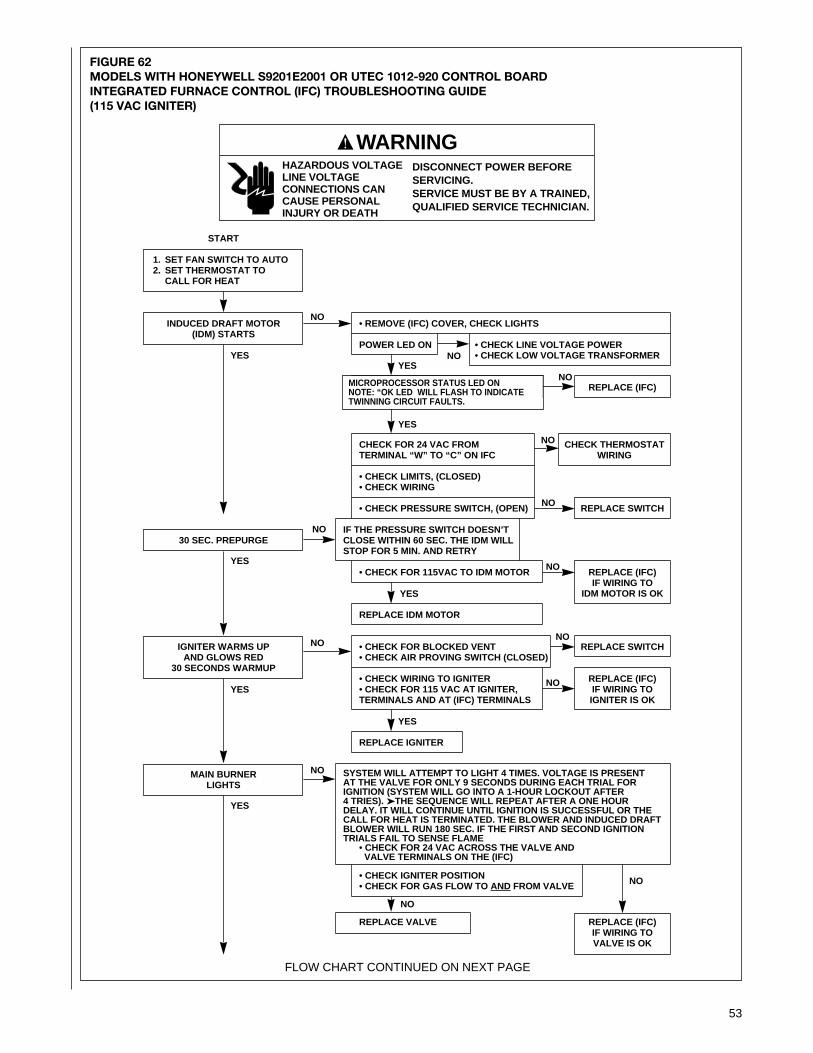
53
FIGURE 62MODELS WITH HONEYWELL S9201E2001 OR UTEC 1012-920 CONTROL BOARDINTEGRATED FURNACE CONTROL (IFC) TROUBLESHOOTING GUIDE(115 VAC IGNITER)
START
1. SET FAN SWITCH TO AUTO2. SET THERMOSTAT TO
CALL FOR HEAT
INDUCED DRAFT MOTOR(IDM) STARTS
30 SEC. PREPURGE
IGNITER WARMS UPAND GLOWS RED
30 SECONDS WARMUP
MAIN BURNERLIGHTS
WARNINGDISCONNECT POWER BEFORESERVICING.SERVICE MUST BE BY A TRAINED,QUALIFIED SERVICE TECHNICIAN.
HAZARDOUS VOLTAGELINE VOLTAGECONNECTIONS CANCAUSE PERSONALINJURY OR DEATH
• REMOVE (IFC) COVER, CHECK LIGHTS
POWER LED ON • CHECK LINE VOLTAGE POWER• CHECK LOW VOLTAGE TRANSFORMER
REPLACE (IFC)
CHECK FOR 24 VAC FROM CHECK THERMOSTATTERMINAL “W” TO “C” ON IFC WIRING
• CHECK LIMITS, (CLOSED)• CHECK WIRING
• CHECK PRESSURE SWITCH, (OPEN) REPLACE SWITCH
IF THE PRESSURE SWITCH DOESN’TCLOSE WITHIN 60 SEC. THE IDM WILLSTOP FOR 5 MIN. AND RETRY
• CHECK FOR 115VAC TO IDM MOTOR REPLACE (IFC)IF WIRING TO
IDM MOTOR IS OK
REPLACE IDM MOTOR
• CHECK FOR BLOCKED VENT REPLACE SWITCH• CHECK AIR PROVING SWITCH (CLOSED)
• CHECK WIRING TO IGNITER REPLACE (IFC)• CHECK FOR 115 VAC AT IGNITER, IF WIRING TOTERMINALS AND AT (IFC) TERMINALS IGNITER IS OK
REPLACE IGNITER
SYSTEM WILL ATTEMPT TO LIGHT 4 TIMES. VOLTAGE IS PRESENTAT THE VALVE FOR ONLY 9 SECONDS DURING EACH TRIAL FORIGNITION (SYSTEM WILL GO INTO A 1-HOUR LOCKOUT AFTER4 TRIES). ➤THE SEQUENCE WILL REPEAT AFTER A ONE HOURDELAY. IT WILL CONTINUE UNTIL IGNITION IS SUCCESSFUL OR THECALL FOR HEAT IS TERMINATED. THE BLOWER AND INDUCED DRAFTBLOWER WILL RUN 180 SEC. IF THE FIRST AND SECOND IGNITIONTRIALS FAIL TO SENSE FLAME
• CHECK FOR 24 VAC ACROSS THE VALVE ANDVALVE TERMINALS ON THE (IFC)
• CHECK IGNITER POSITION• CHECK FOR GAS FLOW TO AND FROM VALVE
REPLACE VALVE REPLACE (IFC)IF WIRING TOVALVE IS OK
FLOW CHART CONTINUED ON NEXT PAGE
NO
NO
NO
NO
NO
NO
YES
YES
YES
YES
YES
YES
YES
NO
YES
NO
NO
NO
NO
NO
!
MICROPROCESSOR STATUS LED ONNOTE: “OK LED WILL FLASH TO INDICATETWINNING CIRCUIT FAULTS.
NO

54
NOTE: STATIC DISCHARGE CAN DAMAGE INTEGRATED FURNACE CONTROL (IFC)
92-22744-08-08
MAIN BURNERREMAINS POWERED
AND LIT
INDOOR BLOWER MOTORSTARTS 20 SECONDS
AFTER GAS VALVE OPENS
SYSTEM RUNSUNTIL CALL FOR
HEAT ENDS
TURN THERMOSTAT TO OFFVALVE SHUTS OFF
FLAME OFF
IDM MOTOR STOPS AFTER 5 SEC.
INDOOR BLOWER MOTORSTOPS AFTER
90/120/160/180 SECONDS
TROUBLESHOOTING ENDS
NOTE: IF (IFC) GOES INTO LOCKOUT WAIT 30 SECONDS THENRESET SYSTEM
• CHECK POLARITY OF 115VAC SUPPLY• CHECK CONTINUITY OF GROUND WIRE• CHECK INSULATION OF IGNITER LEADS• CHECK FLAME SENSE CURRENT (YELLOW LED)
LED IS ON IF FLAME CURRENT IS GOOD.IT FLASHES IF CURRENT IS MARGINAL.
• TURN POWER OFF TO UNIT• CLEAN FLAME SENSOR WITH STEEL WOOL IF LED FLASHES• RESTORE POWER TO UNIT
• IF CHECKS ARE OK, REPLACE (IFC)
• CHECK FOR 115VAC ACROSS REPLACE (IFC) IFBLOWER MOTOR AND BLOWER WIRING TO BLOWERMOTOR TERMINALS (HEAT AND MOTOR IS OKNEUTRAL) ON (IFC)
REPLACE BLOWER MOTOR
NOTE: IF (IFC) GOES INTO LOCKOUT WAIT 30 SECONDS THENRESET SYSTEM
• CHECK CONTINUITY OF GROUND WIRE. NOTE: IF GROUND ISPOOR OR ERRATIC, SHUTDOWN MAY OCCUR OCCASIONALLYEVEN THOUGH OPERATION IS NORMAL AT THE TIMEOF CHECKOUT.• CHECK FLAME SENSE CURRENT
• CHECK FOR EXCESSIVE HEAT AT IGNITER BASE(TEMP. ABOVE 1000 F (538 C) CAUSES SHORT TO GROUND)
• TURN POWER OFF TO UNIT• CLEAN FLAME SENSOR WITH STEEL WOOL• RESTORE POWER TO UNIT
• IF CHECKS ARE OK, REPLACE (IFC)
• CHECK FOR PROPER THEMOSTAT OPERATION• REMOVE VALVE LEAD AT (IFC)IF VALVE CLOSED, RECHECK THERMOSTAT ANDWIRING. IF NOT, REPLACE VALVE.
• CHECK FOR OPEN LIMIT.• REPLACE (IFC)
• CHECK FOR OPEN LIMIT.REPLACE (IFC)
REPEAT PROCEDURE UNTIL TROUBLEFREEOPERATION IS OBTAINED.
YES
YES
YES
YES
YES
YES
YES
NO
NO
NO
NO
NO
NO
NO
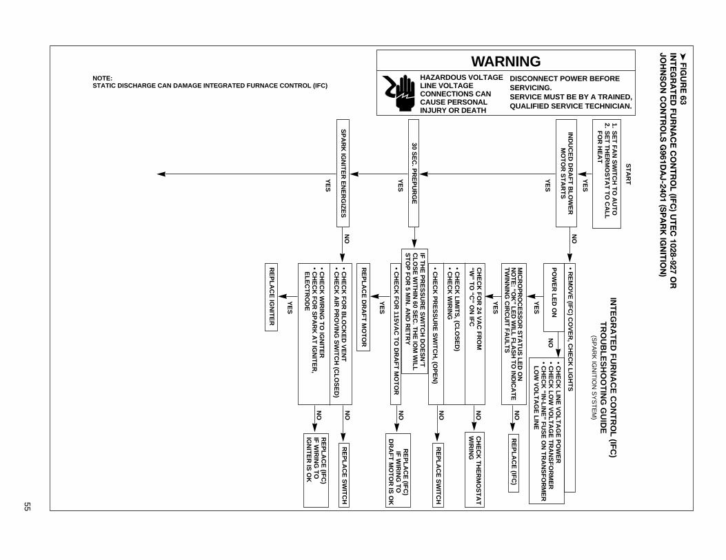
➤FIG
UR
E 63
INT
EG
RA
TE
D FU
RN
AC
E C
ON
TR
OL (IFC
) UT
EC
1028-927 OR
JOH
NS
ON
CO
NT
RO
LS G
961DA
J-2401 (SP
AR
K IG
NIT
ION
)
55
•C
HE
CK
FO
R B
LO
CK
ED
VE
NT
•C
HE
CK
AIR
PR
OV
ING
SW
ITC
H (C
LO
SE
D)
•C
HE
CK
WIR
ING
TO
IGN
ITE
R•
CH
EC
K F
OR
SP
AR
K A
T IG
NIT
ER
,E
LE
CT
RO
DE
1.S
ET
FA
N S
WIT
CH
TO
AU
TO
2.S
ET
TH
ER
MO
ST
AT
TO
CA
LL
FO
R H
EA
T
ST
AR
T
NO
NO
YE
S
YE
S
YE
S
YE
S
YE
S
NO
IND
UC
ED
DR
AF
T B
LO
WE
RM
OT
OR
ST
AR
TS
YE
S
NO
SP
AR
K IG
NIT
ER
EN
ER
GIZ
ES
YE
S
30 SE
C. P
RE
PU
RG
E
RE
PL
AC
E (IF
C)
NO
RE
PL
AC
E S
WIT
CH
NO
RE
PL
AC
E (IF
C)
IF W
IRIN
G T
OD
RA
FT
MO
TO
R IS
OK
NO
RE
PL
AC
E S
WIT
CH
NO
RE
PL
AC
E (IF
C)
IF W
IRIN
G T
OIG
NIT
ER
IS O
K
NO
CH
EC
K T
HE
RM
OS
TA
TW
IRIN
G
•C
HE
CK
LIN
E V
OL
TA
GE
PO
WE
R•
CH
EC
K L
OW
VO
LT
AG
E T
RA
NS
FO
RM
ER
•C
HE
CK
“IN-L
INE
” FU
SE
ON
TR
AN
SF
OR
ME
RL
OW
VO
LT
AG
E L
INE
INT
EG
RA
TE
D F
UR
NA
CE
CO
NT
RO
L (IF
C)
TR
OU
BL
ES
HO
OT
ING
GU
IDE
(SP
AR
K IG
NIT
ION
SY
ST
EM
)
PO
WE
R L
ED
ON
IF T
HE
PR
ES
SU
RE
SW
ITC
H D
OE
SN
’TC
LO
SE
WIT
HIN
60 SE
C. T
HE
IOM
WIL
LS
TO
P F
OR
5 MIN
. AN
D R
ET
RY
•R
EM
OV
E (IF
C) C
OV
ER
, CH
EC
K L
IGH
TS
MIC
RO
PR
OC
ES
SO
R S
TA
TU
S L
ED
ON
NO
TE
: “OK
” LE
D W
ILL
FL
AS
H T
O IN
DIC
AT
ET
WIN
NIN
G C
IRC
UIT
FA
UL
TS
•C
HE
CK
FO
R 115V
AC
TO
DR
AF
T M
OT
OR
RE
PL
AC
E D
RA
FT
MO
TO
R
CH
EC
K F
OR
24 VA
C F
RO
M“W
” TO
“C” O
N IF
C
•C
HE
CK
LIM
ITS
, (CL
OS
ED
)•
CH
EC
K W
IRIN
G
•C
HE
CK
PR
ES
SU
RE
SW
ITC
H, (O
PE
N)
YE
S
RE
PL
AC
E IG
NIT
ER
NOTE:STATIC DISCHARGE CAN DAMAGE INTEGRATED FURNACE CONTROL (IFC)
WARNINGDISCONNECT POWER BEFORESERVICING.SERVICE MUST BE BY A TRAINED,QUALIFIED SERVICE TECHNICIAN.
HAZARDOUS VOLTAGELINE VOLTAGECONNECTIONS CANCAUSE PERSONALINJURY OR DEATH

56
NOTE: IF (IFC) GOES INTO LOCKOUT WAIT 30 SECONDS THENRESET SYSTEM
• CHECK CONTINUITY OF GROUND WIRE. NOTE: IF GROUND ISPOOR OR ERATIC, SHUTDOWN MAY OCCUR OCCASIONALLY EVENTHOUGH OPERATION IS NORMAL AT THE TIME OF CHECKOUT.• CHECK FLAME SENSE CURRENT
• CHECK FOR EXCESSIVE HEAT AT IGNITER BASE.• TURN POWER OFF TO UNIT.• CLEAN FLAME SENSOR WITH STEEL WOOL.• RESTORE POWER TO UNIT.
• IF CHECKS ARE OK, REPLACE (IFC)
YES
NO
NO
MAIN BURNERLIGHTS
YES
NOMAIN BURNER REMAINS
POWERED AND LIT
YES
YES
YES
NOSYSTEM RUNS UNTIL
CALL FOR HEAT ENDS
NOINDOOR BLOWER MOTORSTARTS 20 SECONDS
AFTER BURNER LIGHTS
YES
REPLACE BLOWER MOTOR
REPLACE VALVE IF NOFLOW THRU VALVE
REPLACE (IFC) IF WIRINGTO VALVE IS OK
REPLACE (IFC) IFWIRING TO BLOWERMOTOR IS OK
NOTE: IF (IFC) GOES INTO LOCKOUT WAIT 30 SECONDS THENRESET SYSTEM
• CHECK POLARITY OF 115VAC SUPPLY• CHECK CONTINUITY OF GROUND WIRE• CHECK INSULATION ON IGNITER• CHECK FLAME SENSE CURRENT (YELLOW LED)
LED IS ON IF FLAME CURRENT IS GOOD.IT FLASHES IF CURRENT IS MARGINAL.• TURN POWER OFF TO UNIT.• CLEAN FLAME SENSOR WITH STEEL WOOL IF LED FLASHES• RESTORE POWER TO UNIT
• IF CHECKS ARE OK, REPLACE (IFC)
SYSTEM WILL ATTEMPT TO LIGHT 4 TIMES. VOLTAGE IS PRESENT AT THEVALVE FOR ONLY 8 SECONDS DURING EACH TRIAL FOR IGNITION (SYSTEMWILL GO INTO A 1-HOUR LOCKOUT AFTER 4 TRIES), THE BLOWER ANDINDUCED DRAFT BLOWER WILL RUN 180 SEC. IF THE FIRST AND SECONDIGNITION TRIAL FAIL TO SENSE FLAME.
• CHECK FOR 24VAC ACROSS THE VALVE ANDVALVE TERMINALS ON THE (IFC)
NO• CHECK IGNITER POSITION,• CHECK FOR GAS FLOW TO AND FROM VALVE.
• CHECK FOR 115VAC ACROSS BLOWERMOTOR AND BLOWER MOTOR TERMINALS(HEAT AND NEUTRAL) ON (IFC)
NOTURN THERMOSTAT TO OFFVALVE SHUTS OFF
FLAME OFF
• CHECK FOR PROPER THERMOSTAT OPERATION.• REMOVE VALVE LEAD AT (IFC)IF VALVE CLOSED, RECHECK THERMOSTAT ANDWIRING IF NOT, REPLACE VALVE
YES
NODRAFT MOTOR STOPS AFTER5 SEC.
TROUBLESHOOTING ENDS
• CHECK FOR OPEN LIMIT,REPLACE (IFC)
YES
NOINDOOR BLOWER MOTOR
STOPS AFTER90/120/160/180 SECONDS
• CHECK FOR OPEN LIMIT,REPLACE (IFC)
REPEAT PROCEDURE UNTIL TROUBLEFREEOPERATION IS OBTAINED.
92-22744-12-01

57
FIGURE 64INTEGRATED FURNACE CONTROL (IFC) UTEC 1012-925 (115 VAC IGNITER)
1. SET FAN SWITCH TO AUTO2. SET THERMOSTAT TO CALL
FOR HEAT
START
WARNINGDISCONNECT POWER BEFORESERVICING.SERVICE MUST BE BY A TRAINED,QUALIFIED SERVICE TECHNICIAN.
HAZARDOUS VOLTAGELINE VOLTAGECONNECTIONS CANCAUSE PERSONALINJURY OR DEATH
NO
NO
YES
YES
YES
YES
YES
NO
!
INDUCED DRAFT BLOWERMOTOR STARTS
YES
NOPURGE CONTINUESIGNITER WARMS UP
AND GLOWS RED30 SECONDS WARMUP
YES
5 SEC. PREPURGE
REPLACE (IFC)
NO REPLACE SWITCH
NOREPLACE (IFC)IF WIRING TO
DRAFT MOTOR IS OK
NO REPLACE SWITCH
NOREPLACE (IFC)IF WIRING TOIGNITER IS OK
NO CHECK THERMOSTATWIRING
• CHECK LINE VOLTAGE POWER• CHECK LOW VOLTAGE TRANSFORMER
NOTE: STATIC DISCHARGE CAN DAMAGE INTEGRATED FURNACE CONTROL (IFC)• “OK” LED BLINKS TO INDICATE EXTERNAL FAULTS:(1) BLINK FOLLOWED BY A 2 SEC. PAUSE - 1 HOUR LOCKOUT(2) BLINKS FOLLOWED BY A 2 SEC. PAUSE - PRESSURE SWITCH IS OPEN(3) BLINKS FOLLOWED BY A 2 SEC. PAUSE - LIMIT SWITCH IS OPEN(4) BLINKS FOLLOWED BY A 2 SEC. PAUSE - PRESSURE SWITCH SHORTED
INTEGRATED FURNACE CONTROL (IFC)TROUBLESHOOTING GUIDE
(115 VAC IGNITER)
CHECK FOR 24 VACPOWER FROM “R”TO “C” ON IFC
IF THE PRESSURE SWITCH DOESN’TCLOSE WITHIN 60 SEC. THE IOM WILLSTOP FOR 5 MIN. AND RETRY
• REMOVE (IFC) COVER, CHECK LIGHTS
MICROPROCESSOR STATUS “OK” LED ON
• CHECK FOR 115VAC TO DRAFT MOTOR
REPLACE DRAFT MOTOR
CHECK FOR 24 VAC FROM“W” TO “C” ON IFC
• CHECK LIMITS, (CLOSED)• CHECK WIRING
• CHECK PRESSURE SWITCH, (OPEN)
YES
REPLACE IGNITER
• CHECK FOR BLOCKED VENT• CHECK AIR PROVING SWITCH (CLOSED)
• CHECK WIRING TO IGNITER• CHECK FOR 115VAC AT IGNITER,TERMINALS AND AT (IFC) TERMINALS

58
YES
NO
NO
MAIN BURNERREMAINS POWERED
AND LIT
YES
YES
YES
NOMAIN BURNERREMAINS POWERED
AND LIT
NOINDOOR BLOWER MOTORSTARTS 20 SECONDS
AFTER GAS VALVE OPENS
YES
REPLACE BLOWER MOTOR
REPLACE VALVE IF NOFLOW THRU VALVE
REPLACE (IFC) IF WIRINGTO VALVE IS OK
REPLACE (IFC) IFWIRING TO BLOWERMOTOR IS OK
NOTE: IF (IFC) GOES INTO LOCKOUT WAIT 30 SECONDS THENRESET SYSTEM
• CHECK POLARITY OF 115VAC SUPPLY• CHECK CONTINUITY OF GROUND WIRE• CHECK INSULATION ON IGNITER LEADS• CHECK FLAME SENSE CURRENT (YELLOW LED)
LED IS ON IF FLAME CURRENT IS GOOD.IT FLASHES IF CURRENT IS MARGINAL.• TURN POWER OFF TO UNIT.• CLEAN FLAME SENSOR WITH STEEL WOOL IF LED FLASHES• RESTORE POWER TO UNIT
• IF CHECKS ARE OK, REPLACE (IFC)
NOTE: IF (IFC) GOES INTO LOCKOUT WAIT 30 SECONDS THENRESET SYSTEM
• CHECK CONTINUITY OF GROUND WIRE, NOTE: IF GROUND ISPOOR OR ERATIC, SHUTDOWN MAY OCCUR OCCASIONALLY EVENTHOUGH OPERATION IS NORMAL AT THE TIME OF CHECKOUT.• CHECK FLAME SENSE CURRENT
• CHECK FOR EXCESSIVE HEAT AT IGNITER BASE, (TEMP.ABOVE 1000 F (538 C) CAUSES SHORT TO GROUND)
• TURN POWER OFF TO UNIT.• CLEAN FLAME SENSOR WITH STEEL WOOL.• RESTORES POWER TO UNIT.
• IF CHECKS ARE OK, REPLACE (IFC)
SYSTEM WILL ATTEMPT TO LIGHT 4 TIMES. VOLTAGE IS PRESENT AT THEVALVE FOR ONLY 8 SECONDS DURING EACH TRIAL FOR IGNITION (SYSTEM WILLGO INTO A 1-HOUR LOCKOUT AFTER 4 TRIES), THE BLOWER AND INDUCEDDRAFT BLOWER WILL RUN 180 SEC. IF THE FIRST AND SECOND IGNITION TRIALFAILS TO SENSE FLAME
• CHECK FOR 24VAC ACROSS THE VALVE ANDVALVE TERMINALS ON THE (IFC)
NO• CHECK IGNITER POSITION,• CHECK FOR GAS FLOW TO AND FROM VALVE.
• CHECK FOR 115VAC ACROSS BLOWERMOTOR AND BLOWER MOTOR TERMINALS(HEAT AND NEUTRAL) ON (IFC)
NOTURN THERMOSTAT TO OFFVALVE SHUTS OFFFLAME GOES OUT
• CHECK FOR PROPER THERMOSTAT OPERATION.• REMOVE VALVE LEAD AT (IFC)IF VALVE CLOSED, RECHECK THERMOSTAT ANDWIRING IF NOT, REPLACE VALVE
YES
NODRAFT MOTOR STOPSAFTER 5 SEC.
TROUBLESHOOTING ENDS
• CHECK FOR OPEN LIMIT,REPLACE (IFC)
YES
NOINDOOR BLOWER MOTOR
STOP AFTER90/120/160/180 SECONDS
• CHECK FOR OPEN LIMIT,REPLACE (IFC)
REPEAT PROCEDURE UNTIL TROUBLEFREEOPERATION IS OBTAINED.
92-22744-10-01
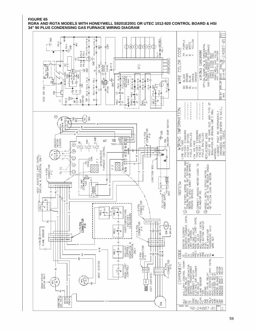
59
FIGURE 65RGRA AND RGTA MODELS WITH HONEYWELL S9201E2001 OR UTEC 1012-920 CONTROL BOARD & HSI34" 90 PLUS CONDENSING GAS FURNACE WIRING DIAGRAM

60
➤ FIGURE 66RGRA AND RGTA MODELS WITH UTEC 1028-927 OR JOHNSON CONTROLS G961DAJ-2401 CONTROL BOARD& SPARK IGNITION34" 90 PLUS CONDENSING GAS FURNACE WIRING DIAGRAM
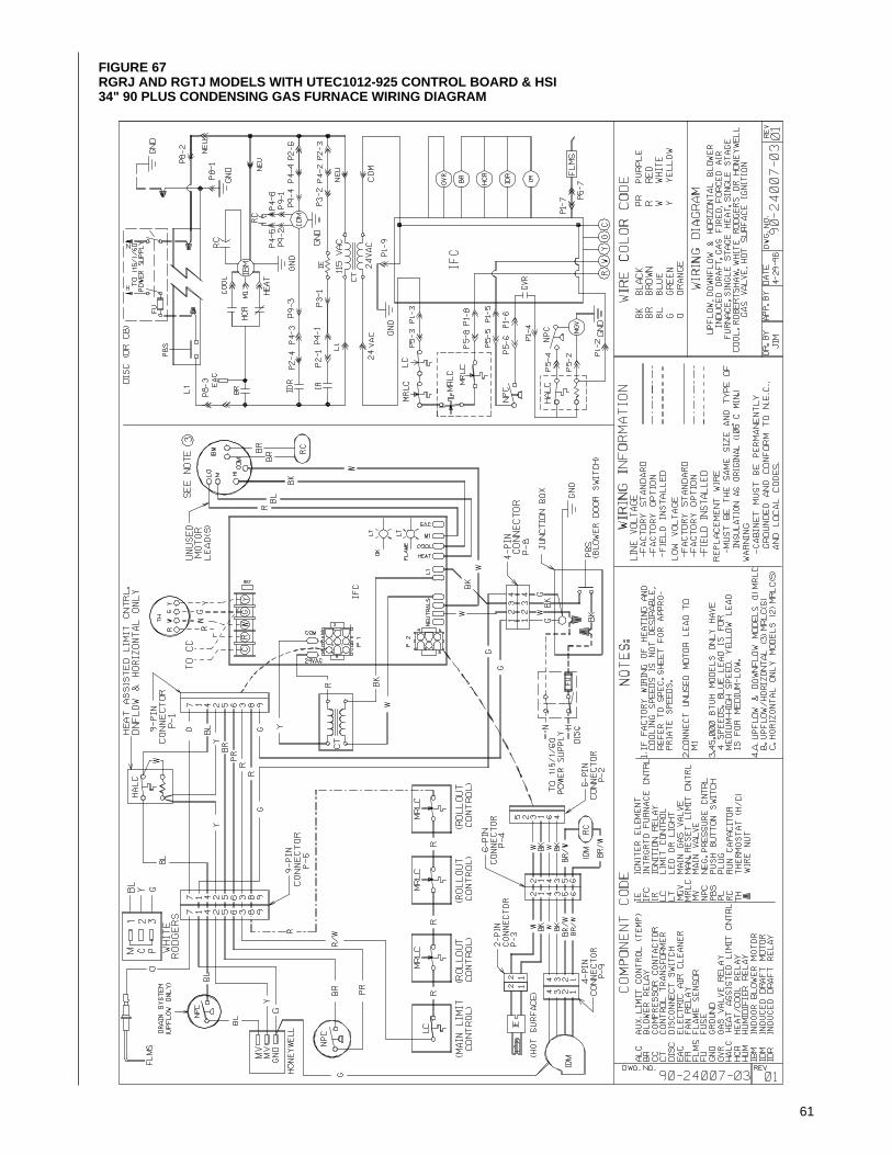
61
FIGURE 67RGRJ AND RGTJ MODELS WITH UTEC1012-925 CONTROL BOARD & HSI 34" 90 PLUS CONDENSING GAS FURNACE WIRING DIAGRAM

62

63

64
Rheem Manufacturing CompanyAir Conditioning DivisionFort Smith, ArkansasCM 1197