installation instruction ofdc-c12-splice version · the installation instruction describes the...
TRANSCRIPT
Page 1© 2017 CommscopeAll Rights Reserved
Installation Instructions
OFDC-C12-SPLICE VERSION OUTDOOR FIBER DISTRIBUTION CLOSURE
TC-1358-2-IPRev. A, July 2017www.commscope.com
1. General Product Information
1.1. Installation Instruction descriptionThe installation instruction describes the necessary steps to install OFDC-C12-splice version.The installation instruction illustrates the use on microsheath cables and flat drop cables. If other feeder and drop cable types are used, supplementary installation steps have to be made. Contact your local Commscope agent to get the relevant accessories and instructions.
1.2. Product description The OFDC is an environmentally sealed enclosure for fiber management system that provides the functions of splicing and passive component integration in the external network. The closure is suitable for pole, wall and cable messaging mounting.
2. Sizing and product information
2.1. Cable diameter rangeCable diameters for main cable: 13 – 15 mm If the diameter of main cable is below 13 mm the gel tape must be addedTo maintain the gel tape in place, use foam.
Cable diameters for branch cable: 8 – 10 mmIf the diameter of branch cable is below 8 mm the gel tape must be addedTo maintain the gel tape in place, use foam.
Cable diameters for 12 drop cable: 2*3 mm, 3 – 5 mm
2.2. CapacitySplices (SMOUV holder positions): 96
Content
1. General Product Information2. Sizing and product information3. Installation conditions precautions4. Preparation of the closure5. Feeder cable installation6. Fiber routing7. Security rope
8. Install organizer in the bottom part9. Drop cable installation10. Closing of the closure11. Mount the strand bracket12. Trademarks13. Contact information
Page 2© 2017 CommscopeAll Rights Reserved
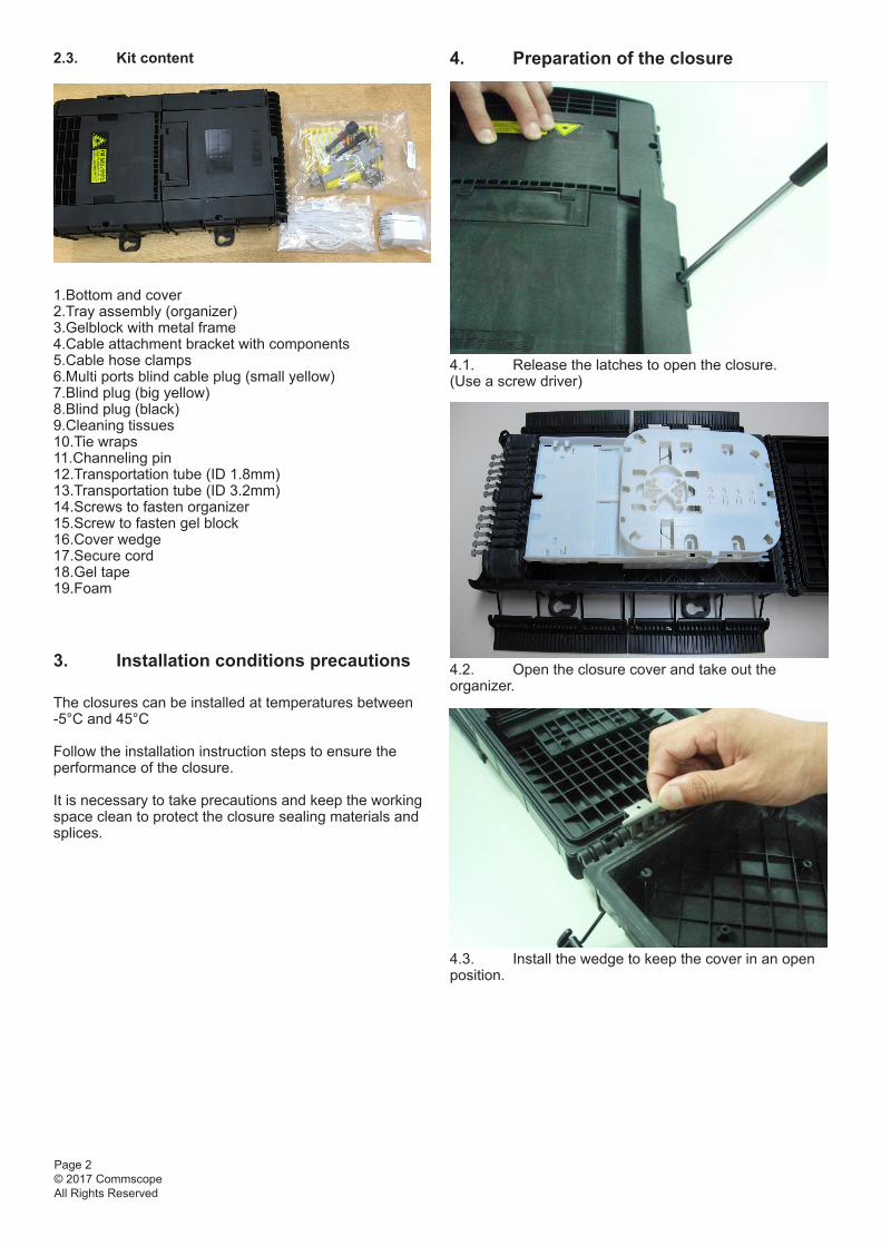
2.3. Kit content
1.Bottom and cover2.Tray assembly (organizer)3.Gelblock with metal frame 4.Cable attachment bracket with components5.Cable hose clamps 6.Multi ports blind cable plug (small yellow) 7.Blind plug (big yellow) 8.Blind plug (black) 9.Cleaning tissues 10.Tie wraps 11.Channeling pin 12.Transportation tube (ID 1.8mm) 13.Transportation tube (ID 3.2mm) 14.Screws to fasten organizer 15.Screw to fasten gel block16.Cover wedge17.Secure cord 18.Gel tape 19.Foam 3. Installation conditions precautions
The closures can be installed at temperatures between -5°C and 45°C
Follow the installation instruction steps to ensure the performance of the closure.
It is necessary to take precautions and keep the working space clean to protect the closure sealing materials and splices.
4. Preparation of the closure
4.1. Release the latches to open the closure. (Use a screw driver)
4.2. Open the closure cover and take out the organizer.
4.3. Install the wedge to keep the cover in an open position.

Page 3© 2017 CommscopeAll Rights Reserved
5. Feeder cable installation
5.1. Make a window cut of 2.2 m. Cut the strength member at a distance of 40 mm (1.6 inch) from the outer jacket.
5.2. Install the cable to the metal bracket, securing the strength member with the metal plates and securing the outer jacket with the hose clamp. Note: Make sure the head of the hose clamp is at the bottom.
5.3. Install the bracket with cables into the designated slots at the side of the organizer.
4.4. Install the 2 screws as shown, do not insert completely ( 2-3 turns).
4.5. Install the screw in the gel block as shown.
4.6. Connect the gel block to the organizer.
4. Preparation of the closure
4.1. Release the latches to open the closure. (Use a screw driver)
4.2. Open the closure cover and take out the organizer.
4.3. Install the wedge to keep the cover in an open position.
Page 4© 2017 CommscopeAll Rights Reserved
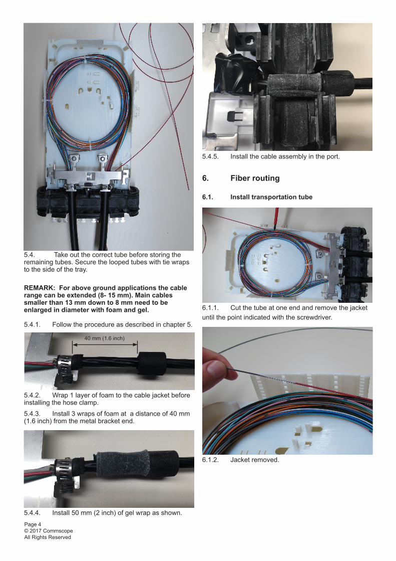
5.4.5. Install the cable assembly in the port.
6. Fiber routing
6.1. Install transportation tube
6.1.1. Cut the tube at one end and remove the jacket until the point indicated with the screwdriver.
6.1.2. Jacket removed.
5.4. Take out the correct tube before storing the remaining tubes. Secure the looped tubes with tie wraps to the side of the tray.
REMARK: For above ground applications the cable range can be extended (8- 15 mm). Main cables smaller than 13 mm down to 8 mm need to be enlarged in diameter with foam and gel.
5.4.1. Follow the procedure as described in chapter 5.
5.4.2. Wrap 1 layer of foam to the cable jacket before installing the hose clamp.
5.4.3. Install 3 wraps of foam at a distance of 40 mm (1.6 inch) from the metal bracket end.
5.4.4. Install 50 mm (2 inch) of gel wrap as shown.
40 mm (1.6 inch)
Page 5© 2017 CommscopeAll Rights Reserved
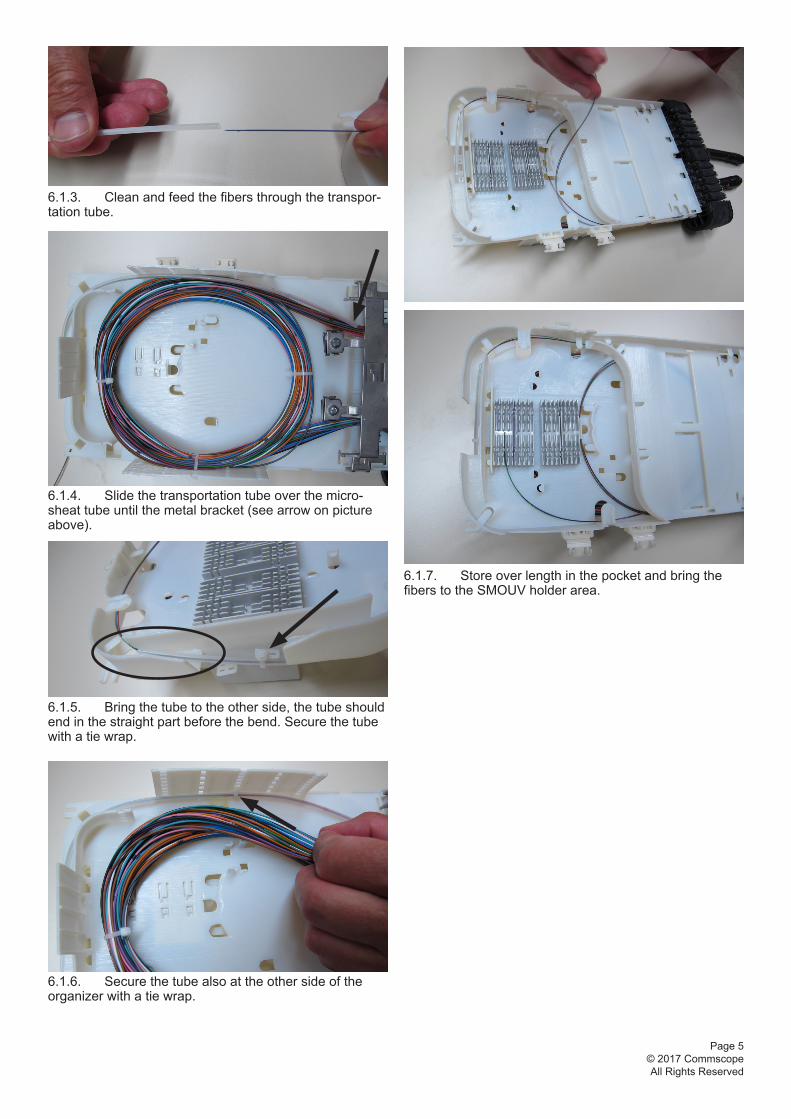
6.1.7. Store over length in the pocket and bring the fibers to the SMOUV holder area.
6.1.3. Clean and feed the fibers through the transpor-tation tube.
6.1.4. Slide the transportation tube over the micro-sheat tube until the metal bracket (see arrow on picture above).
6.1.5. Bring the tube to the other side, the tube should end in the straight part before the bend. Secure the tube with a tie wrap.
6.1.6. Secure the tube also at the other side of the organizer with a tie wrap.

Page 6© 2017 CommscopeAll Rights Reserved
7. Security rope
7.1. Install the security rope.
8. Install organizer in the bottom part
8.1. In case of unused cable ports, install the corresponding blind plugs.
8.2. Slide the organizer in the bottom part, under the head of the installed screws, as shown.
8.3. Tighten the 3 screws to secure the organizer in the bottom part.
Page 7© 2017 CommscopeAll Rights Reserved
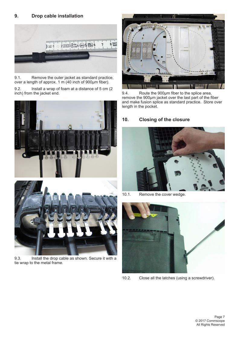
9. Drop cable installation
9.1. Remove the outer jacket as standard practice, over a length of approx. 1 m (40 inch of 900µm fiber).
9.2. Install a wrap of foam at a distance of 5 cm (2 inch) from the jacket end.
9.3. Install the drop cable as shown. Secure it with a tie wrap to the metal frame.
9.4. Route the 900µm fiber to the splice area, remove the 900µm jacket over the last part of the fiber and make fusion splice as standard practice. Store over length in the pocket.
10. Closing of the closure
10.1. Remove the cover wedge.
10.2. Close all the latches (using a screwdriver).
Page 8© 2017 CommscopeAll Rights Reserved
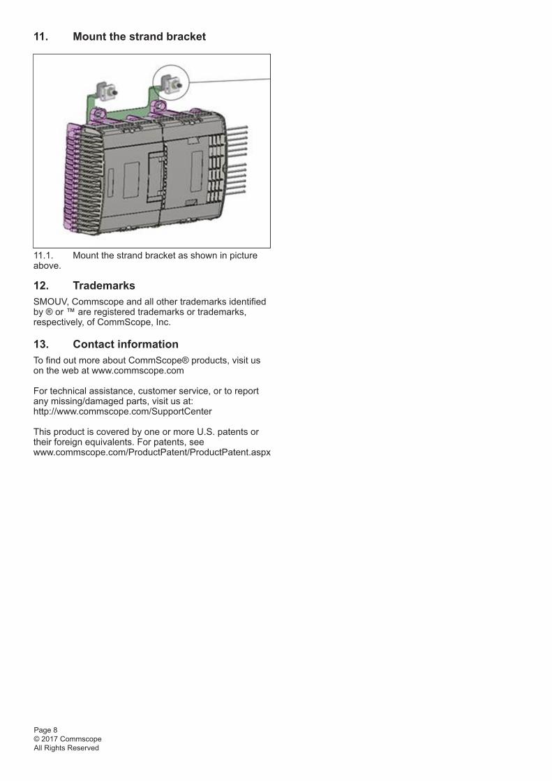
11. Mount the strand bracket
11.1. Mount the strand bracket as shown in picture above.
12. TrademarksSMOUV, Commscope and all other trademarks identified by ® or ™ are registered trademarks or trademarks, respectively, of CommScope, Inc.
13. Contact informationTo find out more about CommScope® products, visit us on the web at www.commscope.com
For technical assistance, customer service, or to report any missing/damaged parts, visit us at: http://www.commscope.com/SupportCenter
This product is covered by one or more U.S. patents or their foreign equivalents. For patents, seewww.commscope.com/ProductPatent/ProductPatent.aspx