installation & instruction manual · horizon instruments, inc. title: p-1000 installation &...
TRANSCRIPT

HORIZON INSTRUMENTS, INC. Title: P-1000 INSTALLATION & INSTRUCTION MANUAL Number: P103050 Revision: E Page: 1 of 23
P103050 – P-1000 INSTALLATION & INSTRUCTION MANUAL

HORIZON INSTRUMENTS, INC. Title: P-1000 INSTALLATION & INSTRUCTION MANUAL Number: P103050 Revision: E Page: 2 of 23
REVISION PAGEORIGINAL NUMBER NEW NUMBER DATE INITIAL DESCRIPTION
P103050 Rev. A P103050 Rev. B 04/24/91 tjkII Added Graphics
P103050 Rev. B P103050 Rev. C 09/16/91 tjkII Updated for STC Release
P103050 Rev. C P103050 Rev. D 03/12/92 tjkII
Added installation checklist,landscape format used, new covergraphic, revised features section
and the warranty changed.
P103050 Rev. D P103050 Rev. E 05/01/03 GAZAddress change with minor text
changes.

HORIZON INSTRUMENTS, INC. Title: P-1000 INSTALLATION & INSTRUCTION MANUAL Number: P103050 Revision: E Page: 3 of 23
TABLE OF CONTENTS
Introduction 4 Maintenance 19P-1000 Features 5 Trouble-Shooting 19Technical Specifications 6 Common Failures of Ignition System 21RTCA Environmental Qualification Statement 7 Warranty 22Certification 8Theory of Operation 9Display Features 10 Figure 1, P-1000 Features 5
Liquid Crystal Display 10 Figure 2, Typical Signal on Magneto P-Leads 9Status Indicators 10 Figure 3, Typical Magneto Electrical Installation 9RPM ACR Indicators 11 Figure 4, Magneto Ignition System Electrical Diagram 10MAG-DROP Display Mode 11 Figure 5, Rear Panel Connections 16
Operation 11 Figure 6, Typical Single Engine Magneto Locations 16LED Dimming 11 Figure 7, Optimum LCD Viewing Angles for Installation 18Tachometer Control 12 Figure 8, Typical Wiring Diagram 18Engine Clock 12Reset 12
Installation 13Static Precautions 13Unpacking and Inspecting the Equipment 13The Installation/Check-Out Sequence 13Connections 16Removal of Mechanical Tachometer 17Instruments Mounting 17Circuit Breaker 18

HORIZON INSTRUMENTS, INC. Title: P-1000 INSTALLATION & INSTRUCTION MANUAL Number: P103050 Revision: E Page: 4 of 23
INTRODUCTION
Thank You for purchasing the Horizon Instruments’ P-1000 Digital Aircraft Tachometer. Many features have been incorporated into thedesign of the P-1000 insuring simple operation and long life. The P-1000 represents the state-of-the-art in applying computertechnology to aircraft engine control and will prove to be invaluable in the reliable and safe operation of your aircraft.
The P-1000 functions as two fully independent digital tachometers that monitor the signals received from the primary circuits of theaircraft’s magnetos. The internal right and left tachometers independently determine engine RPM, which is then average and displayedfor the pilot. The superior reliability of the tachometer design is due to the use of two separate magneto signals to generate two identicalRPM readings. If either magneto fails, the tachometer will continue to display RPM from the remaining functional magneto. No externalprobes or sensors are required to be installed in the harsh engine environment, further reducing the possibility of failure, and simplifyinginstallation.
Easy installation is facilitated by wiring the P-1000 to the P-Leads of the ignition switch. In most cases, no additional wires need be runinto the engine compartment.
To be sure of obtaining the best possible performance from the P-1000 please be sure to read this Instruction Manual carefully andbecome thoroughly familiar with the operation of the P-1000 before staring its use.
KEEP THIS MANUAL HANDY FOR FUTURE REFERENCE.

HORIZON INSTRUMENTS, INC. Title: P-1000 INSTALLATION & INSTRUCTION MANUAL Number: P103050 Revision: E Page: 5 of 23
A Right Magneto Signal Status Indicator. Turns on with the Loss of Signal from the RightMagneto. Flashes when the Right Internal Tachometer is Disabled.
B Magneto Error Indicator. Illuminates to indicate that there is a difference in RPMreported from each Magneto.
C Left Magneto Signal Status Indicator. Turns on with the Loss of Signal from the LeftMagneto. Flashes when the Left Internal Tachometer is Disabled.
D Green, “Normal Operating” Range Indicator. Illuminates when the Engine RPM iswithin its specified normal operating ranges.
E Yellow, “Warning, Cautionary or Transient” Range Indicator. Illuminates when EngineRPM is within its specified Cautionary or Transient Operating Ranges.
F Red, “Restricted Operating” Range Indicator. Illuminates when the Engine RPM iswithin its specified Restricted Operating Ranges.
UP TO FIVE SEPARATE RPM RANGES MAY BE FACTORY PROGRAMMED.
G Placard AreaH Full 4 Digit High Visibility Back-Lit ½” Liquid Crystal DisplayI RPM Overspeed Trap Recall Button/Right Tachometer Enable/Disable.J RPM Overspeed Trap Clear Button/Indicator Dimmer.
Figure 1, P-1000 Features
K Engine Hours Recall Button/Left Internal Tachometer Disable. ENGINE HOUR METER CANBE FACTORY PRE-SET TO START WHERE THE REPLACED TACHOMETER STOPPED.
Two fully independent tachometers in one panel-mounted instrument increase tachometer reliability in case of either magneto’sfailure. Tachometer monitors both magneto P-Leads for redundant RPM sensing and magneto performance comparisons. Non-Volatilememory won’t forget engine hours or factory pre-sets, no battery required. Eliminates tachometer cables, oil seal problems and accuracyproblems associated with mechanical tachometers. Light weight, sturdy construction, easy to install.
Long term stability due to the use of all digital techniques, accuracy better than 1 RPM. Vibration, temperature, andelectromagnetic interference, do not affect accuracy. Detection of RPM differences between magnetos and possible magneto failure.Automatic display of “MAG-DROP” RPM when a magneto pre-flight is performed. Visual indication of possible “HOT-MAG” or shortedmagneto conditions. Operates with any number of engine cylinders.

HORIZON INSTRUMENTS, INC. Title: P-1000 INSTALLATION & INSTRUCTION MANUAL Number: P103050 Revision: E Page: 6 of 23
TECHNICAL SPECIFICATIONSInput Frequency Range: Up to 400 magneto firings per second, per tachometer
12,000 RPM on a 4 cylinder engine, 5,333 RPM on a 9 cylinder engine
Input Signal Voltage: 100 to 1000 Volts AC
Accuracy: +/- ½ RPM, each tachometer
Cylinder Configurations: 4,6,7,8,9,11,12,14
Input Impedance: Greater than 500,000 ohms, each tachometer input
Power Requirements: 7.5 – 31 Volts, DC, 200 ma. max
Environment:Weight: 1.5 lbs.
Dimensions: 3 inch MSM33638 Case, 2 ¾” deep
Switch Operational Life: Greater than 250,000 cycles
Cabling: Shielded P-Lead wire to ignition switch. MS3106A-14S-6S Connector with AN-3057-6 Strain Relief
MTBF 20,000 Hours
Warranty: Limited Two Years, Parts & Labor.
Engine Hours Clock: Accurate to less than 1 hour error in 2000 hours. Records real time when engine RPM is greater than 800.
Software Certifications: Software certified to RTCA DO-178A, level 2.

HORIZON INSTRUMENTS, INC. Title: P-1000 INSTALLATION & INSTRUCTION MANUAL Number: P103050 Revision: E Page: 7 of 23
The P-1000 Electronic Digital Engine Tachometer is designed to meet the following environmental test categories of RTCA DO-160-C.
CONDITIONS PARAGRAPHNUMBER DESCRIPTION OF CONDUCTED TESTS CONDITIONS PARAGRAPH
NUMBER DESCRIPTION OF CONDUCTED TESTS
4 Tested to categories A1 & B1. Fluids Susceptibility 11 Equipment Identified as “X”.No Test Required.
4.5.1 Ground Survival (-55 C) & Low OperatingTemperature Tests (-20 C)
Sand & Dust 12 Equipment Identified as “X”.No Test required.
4.5.2Ground Survival (+85 C) & High Short
Time Operating Temperature Test (+70C).
Fungus 13 Equipment Identified as “X”.No Test Required.
4.5.3 High Operating Temperature Test (+55C) Salt Spray 14 Equipment Identified as “X”.
No Test Required.
4.6.1 Altitude(+25,000Ft)
Magnetic Effect 15 Tested Per Category “Z”.No compass defection in each axis.
4.6.2 Decompression Tests(8,000Ft to 25,000Ft) Power Input 16
Tested Per Category “B”.EUT operated normally
during all test conditions.
Temperature&
Altitude
4.6.3 Overpressure Tests(-15,000Ft) Voltage & Spike, Conducted 17
Tested Per Category “B”.EUT displayed no malfunctions or
degradations during testing.
Temperature Variation 5Tested Per Category “B”. Equipment will
withstand better than 5 C/mintemperature change.
Audio FrequencyConducted Susceptibility 18
Tested Per Category “B”.EUT displayed no malfunctions or
degradations during testing.
Humidity 6 Tested per Category “A”.95% Humidity Induced Signal Susceptibility 19
Tested Per Category “B”.The EUT showed no signs of susceptibility
during this test.
7.2 Operational Shock Test, 6gs in 11ms. ½sine, 3 shocks per axis, each direction.
Radio FrequencySusceptibility 20
Tested Per Category “U”.The EUT showed o signs of susceptibility
during this test.Shock
7.3Crash Safety Test, impulse and SustainedShock. 15gs in 11ms. ½ sine performed
on each axis.Radio Frequency Emissions 21
Tested Per Category “B”.The EUT’s emissions were within the test
requirements.
Vibration 8Tested per “Standard Vibration”
requirements. Resonance scans detect noresonance in each axis.
Lightning Induced TransientSusceptibility 22
Tested Per Category “K”.These tests had no
effect upon the EUT.Explosion 9 Test Not Applicable. Lightning Direct Effects 23 Tested Per Category “X”.
Waterproofness 10Equipment Identified as “X”.
No Test Required. Icing 24 Tested Per Category “X”.
HORIZON INSTRUMENTS, INC. Title: P-1000 INSTALLATION & INSTRUCTION MANUAL Number: P103050 Revision: E Page: 8 of 23
CERTIFICATION
The P-1000 is installable into an aircraft under one of the following conditions:
1. With an STC issued for your model aircraft allowing the P-1000 to replace the existing mechanical tachometer.
2. With a one-time-only STC issued for installation of the P-1000 on your aircraft, this is typically referred to as a “Field Approval”.
A P-1000 purchased with an STC for replacement of the existing mechanical tachometer will have attached to this documentationpackage:
Supplemental Instructions and Drawings pertaining to the specific installation of the P-1000 in the indicated aircraft. Flight Manual Supplement A copy of the applicable STC
The Supplemental STC information supplied with a P-1000 is dependent upon the information supplied to Horizon Instruments, Inc. at thetime the P-1000 is ordered. If this information is erroneous, applicable to a different type of aircraft, or missing, do not proceed withinstallation. Contact the Horizon Instruments, Inc. Technical support staff for further instructions.
NOTE:The STC Approval accompanying a P-1000 tachometer is considered proprietary information by horizon Instruments, Inc. and is notapplicable to any other manufacturer’s equipments.

HORIZON INSTRUMENTS, INC. Title: P-1000 INSTALLATION & INSTRUCTION MANUAL Number: P103050 Revision: E Page: 9 of 23
THEORY OF OPERATION
The P-1000 operates by timing the alternating electrical signalsgenerated by an operating magneto, see Figure 2, and mageavailable on the magneto’s “P” or grounding leads. Becausereciprocating engine aircraft have two magnetos on each engine
(See Figure 3), the P-1000provides two terminals forconnection to these “P” leads ofthe right and left magnetos of theengine. These “P” lead signalsare generally only a few hundredvolts as compared to thesecondary output of the magneto,which may generate tens of
thousands of volts used to create sparks at the spark plugs.
RPM is derived from the repetition rate of the signals received fromthe magnetos, and not the amplitude or shape of these signals. Thisrate corresponds to the firing of the engine’s spark plugs, and thus,the turning of the engine.
The Microprocessor functions as two internal tachometers. It has theability to compare and store the RPM of each tachometer.A difference of RPM reported from the two magnetos of the sameengine indicates that one of the magnetos may be failing (i.e. Mis-firing, severe fouling, sticking or floating points, etc.).
The RPM displayed on the LCD is the average of the right and left tachometer’s RPM. Thus, if either tachometer begins to fluctuate or acterratically, due to failure in its ignition system, the error will show in the display. Mechanisms are provided to mask these erroneous RPMvalues and allow operation from the signal of the functional magneto.
Loss of a signal from either magneto is detected by the corresponding internal tachometer and a signal status indicator is turned on toindicate the error. Short term (<½ second) differences between the right and left tachometers are also indicated to the pilot with a yellowstatus indicator.

HORIZON INSTRUMENTS, INC. Title: P-1000 INSTALLATION & INSTRUCTION MANUAL Number: P103050 Revision: E Page: 10 of 23
Engine hours are recorded in real time beginning when theengine is assumed to be able to sustain combustion, at orabove 800 RPM. A high accuracy engine clock yields trueTBO times (engines are rated in real hours, not RPM-hours)and more accurate fuel consumption calculations.
Using the internal microprocessor to compare RPMs fromeach internal tachometer against a previously knownhighest RPM, and storing the new highest RPM creates the“Overspeed Trap” feature. Provisions are made to clearthis trap at any time. The Overspeed Trap is saved whenthe P-1000 is turned off.
DISPLAY FEATURES
LIQUID CRYSTAL DISPLAYThe P-1000 provides easy to read ½ inch high characterson a liquid crystal display (LCD). A “straight line”(displayed using hyphens) is displayed on the LCD when theP-1000 is not receiving a signal from either magneto. Thisis generally noticeable when the P-1000 is turned on andthe engine is not started.
STATUS INDICATORSWhen no signal is received from either the right magneto or left magneto (See Figure 1), the P-1000 will turn on a corresponding right orleft red magneto signal “Status” indictor. The status indicators are located on the upper left of the tachometer face and can indicate a hotmagneto (open circuit) or grounded magneto (breached insulation or broken ignition switch) condition. The indicators turn on after ½second passes without receiving a pulse from a magneto, and will turn off when the signal is restored.
Another status indicator is located between the red magneto signal indicators. This yellow indicator is a warning that the P-1000 hasdetected different RPM from the signals provided by each magneto. This is typical of a failing set of points or an intermittent wiringproblem. The yellow status indicator may be accompanied by a red magneto signal status indicator, but under some conditions, mayappear by itself. See the Troubleshooting section for more information. This indicator operates as a threshold set at the maximumallowable difference between the mag-drop readings of each magneto.

HORIZON INSTRUMENTS, INC. Title: P-1000 INSTALLATION & INSTRUCTION MANUAL Number: P103050 Revision: E Page: 11 of 23
RPM ARC INDICATORSThree large LED type indicators are provided at the upper right corner of the P-1000 face to indicate the RPM operating range of theengine (See Figure 1). A “Normal Operating “ green, “Caution” yellow, and “RED-LINE” red LED are provided. The RPM settings atwhich these indicators activate are presettable at the factory. Five separate RPM arcs can be factory programmed into the P-1000.
MAG-DROP DISPLAY MODELoss of either magneto signal causes the P-1000 to turn the appropriate status indicator, remember the engine RPM at the time the signalwas lost, and display the drop in engine RPM that resulted from the loss of the magneto. When this feature is used in conjunction with theignition switch, pre-flight magneto performance tests, or “Mag-Drop”, can be easily and accurately performed. During this mode ofoperation, the LCD should show a small RPM number, normally preceded by a minus sign (“-“) indicating that the engine slowed down.A display without a minus sign indicates an engine that has increased in speed. If the loss of signal remains for more than fifteenseconds, the P-100 will revert back to displaying the engine RPM, determined from the remaining functioning magneto.
OPERATIONThree buttons on the face of the P-1000 control the information being displayed to the pilot. These buttons have two modes of operation:press-and-hold, and press-and-release. The press-and-hold operation is used to control information displayed on the liquid crystaldisplay. Each button must be pressed and held for one second to change the display. Pressing and holding the right button causes theOverspeed trap to be displayed. This function is denoted on the P-1000 face by the word “TRAP” above the button. Pressing andholding the center button for one second will cause a zero to be displayed. This causes the Overspeed trap to be cleared, and the buttonis marked with eh word “CLEAR”. Pressing and holding the left button for one second will cause the engine hours to be displayed. Whilethe button is being held, the integer portion of the engine hours is displayed. Upon release of the button, the fractional portion of theengine hours is displayed for five seconds, then the display reverts back to displaying RPM. This function is marked on the P-1000 by theword “HOURS” above the left button. Press-and-release operations modify the operation of the internal tachometers and control displaycharacteristics. The press-and-release operation must occur within one second to distinguish the operation from the press-and-holdoperations described above.
LED DIMMINGA press-and-release operation on the center button causes the LED indicators (except for the red LEDs) to be dimmed. Pressing the buttonagain restores the LEDs to full intensity. This feature is handy for night flying because an LED bright enough to overcome sunlightwashout may be annoyingly bright at night. This function is marked “DIM” on the P-1000 face under the center button. The red RPMrange indicator is not dimmable.

HORIZON INSTRUMENTS, INC. Title: P-1000 INSTALLATION & INSTRUCTION MANUAL Number: P103050 Revision: E Page: 12 of 23
TACHOMETER CONTROLBecause a bad or failing magneto may affect the RPM displayed on the liquid crystal display (see Theory section), a mechanism isprovided to mask the erroneous RPM information from the display. An Erroneous or erratic RPM display may be accompanied by one ormore of the status LEDs illuminating.
Press-and-release operation of the right and left buttons causes the right and/or left tachometers to be alternately masked and un-masked from the display. This is a toggle type feature: a masked tachometer will be un-masked, or allowed to affect the display, whenthe button is pressed, or an un-masked tachometer will be prevented from affecting the display when the button is pressed.
When the RPM displayed on the P-100 is suspected to be wrong, is jittery or erratic, does not track the engine properly, or one or more ofthe status indicators are turned on or are flickering, it is likely that one of the ignition systems has a problem.
The procedure to find the bad ignition system is to isolate the RPM from each internal tachometer can check the results. Mask eachtachometer, one at a time, starting with the tachometer corresponding with any flickering red status LED to try to stabilize the RPM on thedisplay. A tachometer that appears to be varying wildly or not properly tracking the engine is the culprit and should be masked from thedisplay to allow normal operation of the P-1000 on the remaining good magneto.
A tachometer that is masked is indicated by the corresponding status LED flashing regularly at a one second rate. Care should be takennot to interpret this indication as a loss of signal condition. The yellow status indicator is inhibited when either tachometer is masked.
ENGINE CLOCKYour tachometer may have been pre-programmed at the factory for other than zero engine hours. When ordering your P-1000, a reviewof your logs may have been necessary to determine the correct time for the tachometer display. Any correction or change in time must berecorded in the appropriate log book.
Recording tachometer, such as the P-1000, are considered by the FAA to record engine hours, not airframe hours. Thus, the tachometershould be ordered with zero hours if being installed with a zero time engine. Allowing the tachometer to run past engine changes inhopes to accumulate total “Time In Service” is not proper, as the engine operates long before the aircraft leaves the ground, see FAR 1.0.
Also, Horizon Instruments, Inc. provides a service to zero or correct your engine hours when engines are changed, or to adjust atachometer display for the proper engine hours reading.
RESETThe computer within the P-1000 may be manually reset if it is suspected that it is not operating properly. To accomplish the reset,simultaneously press the center and right buttons. The P-1000 should proceed through its self-check tests and resume full operation.

HORIZON INSTRUMENTS, INC. Title: P-1000 INSTALLATION & INSTRUCTION MANUAL Number: P103050 Revision: E Page: 13 of 23
INSTALLATIONAt all times, installation procedures should follow good aviation installation practices as per FAA Advisory Circulars 43.13-1A Chapter 2and 43.13-2A Chapter 11, and this manual. Because the P-1000 is installed and approved using a Supplement Type Certificationprocedure, supplemental instructions specific to your aircraft are included with this tachometer. These additional instructions takeprecedence over this manual.
STATIC PRECAUTIONSProper operation of the P-1000 requires that all grounding straps to the engine block and instrument panel be in place. The magneto P-Leads carry signals that are very prone to conduction into adjacent circuits/wires/metals. An adequate return path to the magneto mustbe maintained to prevent interference with other electronics equipment.
Normally the P-1000’s ground terminal for the power buss is adequate for this purpose, however, the wires connecting the P-1000 to themagnetos are shielded, and those shields may be grounded at the magneto, or to the shields of existing P-Leads at the ignition switch.Older aircraft may not employ shielding wire.
UNPACKING & INSPECTING THE EQUIPMENTExercise care when unpacking the P-1000. Make a visual inspection of the tachometer for any evidence of damage incurred duringshipping.
It is good practice to retain the shipping containers and packing materials if it should ever become necessary to return the P-1000 forservice, maintenance, or modification.
Save all packing slips, invoices, warranties, and manuals in a secure area for future reference.
The shipping container will need to be returned to Horizon Instruments, Inc. to substantiate any claims of damage due to shipment. Priorto returning any product to Horizon instruments, Inc., please call for a return materials authorization number so that your product can beproperly and expediently tracked and processed.
Verify the RPM arc information placarded on the face of the P-1000 to correspond with the red, yellow and green arcs on the existingmechanical tachometer, or to the engine/propeller manufacturer’s specifications.

HORIZON INSTRUMENTS, INC. Title: P-1000 INSTALLATION & INSTRUCTION MANUAL Number: P103050 Revision: E Page: 14 of 23
THE INSTALLATION/CHECK-OUT SEQUENCEThe following steps are a general outline for the installation and checkout of the P-1000 Tachometers:
1 Verify that all tools and materials to complete the installation are available.
2 Locate the tachometer on the instrument panel and verify that there is a sufficient clearance for the P-1000 and attached cable behind the panelwhen installed.
3 Locate the recommended circuit breaker installation on the electrical panel. Verify that the cable provided will reach from the P-1000installation to the circuit breaker.
4 Locate the ignition switch on the electrical panel. Again verify that sufficient length of cable is available to reach from the P-1000 to the ignitionswitch. The P-Lead wires should be routed away from any radio or other sensitive electronic equipment, and maintains proximity to groundedpanel structures. Maintain three inches clearance from any other electrical wiring.
5 Determine the routing of the cable from the P-1000 to the ignition switch and circuit breaker. Remember to leave adequate service loops andproperly strain relieves the cable ends.
6 Cut the power wires to proper length, strip 3/8” from the ends and attached the ring-tongue terminals supplied.
7 Verify that the main power switch is turned “OFF”.
8 Attach the black wire to a suitable ground, preferably to a metal surface or supporting structure.9 Install the circuit breaker. Turn on the main power switch and verify the operation of the circuit breaker. Turn off the main power switch. Note:
the circuit breaker should be installed on the main power buss, not the instrument power buss.
10 Attach the white wire to the circuit breaker load terminal.11 Attach the circular connector to the P-1000. Be sure to screw the retaining ring all the way to the base of the mating P-1000 connector. Turn
on the main power switch and verify that the P-1000 turns on. The P-1000 will flash the tachometer’s configuration number, which identifiesthe tachometer for use with a specific aircraft/engine combination, and a software version code. The version code has a decimal point in it, theconfiguration code does not.
12 Turn off the main power switch.
13 Attach the left and right P-Lead wires to the ignition switch. Be sure to make the proper left and right connections to the left and right magnetos.Use the ring-tongue connectors wherever possible. DO NOT CUT OR SPLICE THESE CABLES. They contain shields to protect other instrumentsin the aircraft from interference from ignition noise. If the shielded wires are too short, please contact Horizon Instruments, Inc. for a longercable. Be sure that no frayed wires are present, and that all screw connections are secure.
14 At this point, the P-1000 may be placed in a secure location prior to stating the engine.

HORIZON INSTRUMENTS, INC. Title: P-1000 INSTALLATION & INSTRUCTION MANUAL Number: P103050 Revision: E Page: 15 of 23
15 Turn on the main power switch and verify the P-1000 again turns on.
16 Press and hold the left button and verify the integer portion of the engine hours is correct as ordered. Release the switch and verify that thedecimal portion of the engine hours is correct.
17 Tap the left button and note that the left magneto signal loss indicator begins flashing. This indication shows that the left internal tachometerhas been masked from the display. Press the button again to stop the flashing.
18 Tap the right button and note that the right magneto signal loss indicator begins flashing. This indication shows that the right internaltachometer has been masked from the display. Press the button again to stop the flashing.
19 Tap the center button to dim the indicators, tap it again to restore to full intensity.
20 Prepare the aircraft for a safe engine start. Start the engine. The P-100 will show RPM within 2 seconds of engine starting. This startup periodis used to train the tachometer. The display should faithfully follow the engine speed. Because cold engines, and engines operating out of theirpower bands will operate roughly, the tachometer can show sizable engine RPM variation.
21 At a suitable run-up area, perform a magneto drop check per your aircraft’s flight manual. Remember to maintain the ignition switch at eachposition for a minimum of ten seconds, and always return to the “Both” position between grounding each agneto, ie. Move the switch asfollows: BOTH-LEFT-BOTH-RIGHT-BOTH. As each magneto is grounded, not the LCD will show the change in engine RPM. This display lastsfor 15 seconds, and then actual RPM is presented on the LCD.
22 Return the engine idle. Press the “Trap” button and hold it. Observe the maximum engine RPM achieved during the run-up operation.
23 Press and hold the “Clear” button. The LCD will show zero.
24 Press the “Trap” button and hold it again. Observe the maximum engine RPM achieved since the “Clear” button was pressed.
25 If possible, during engine operation compare the P-1000 RPM readings to your mechanical tachometer to verify that the P-1000 is operatingproperly.
26 Return the aircraft to the work area, and shut off.
27 Remove the mechanical tachometer and store.
28 Remove the tachometer drive cable and housing.
29 Patch the firewall hole using proper and approved materials and procedures.
30 Install the dust cap over the engine’s tachometer drive attachment. Insure that the cap is rightly installed and won’t shake loose. Use safetywire to secure cap in place. Periodically check the cap for proper fit, tightness, and oil leakage during its installation life.
31 Safety wire the cable to the tachometer. Two separate loops of stainless steel wire can be looped through each side of the connector andthrough corresponding drilled fillister head screw on the P-1000.
32 Install the P-100 in the instrument panel.

HORIZON INSTRUMENTS, INC. Title: P-1000 INSTALLATION & INSTRUCTION MANUAL Number: P103050 Revision: E Page: 16 of 23
33 Secure all wires.
34 Make proper log book entries, including any deviations or corrections in engine/airframe time indicated on the tachometer.
35 Note any deviations in tachometer or circuit breaker location from those positions recommended in the drawing accompanying anySTC’d P-1000.
CONNECTIONS
A standard MS style connector is supplied on the rear of theP-1000 tachometer with six connections, as illustrated inFigure 5.
Using the pre-wired cable provided, black wire labeled“Ground” is connected to a suitable electrical ground of theaircraft’s instrument power buss. The white, un-shielded, wirelabeled “Battery+” is connected to supplied circuit breaker,connected to the positive voltage connection of the mainpower buss. Position the circuit breaker as indicated in anyincluded installation drawings.
The “Right Magneto P-Lead” and “Left Magneto P-Lead” wiresare connected to the right and left magneto P-leads at the
ignition switch (see Figure 6). Do not connect any part of the P-1000 to a spark plug wire or any part of the high voltage secondaryignition circuit as serious damage may result to the P-1000 and to the pilot. Do not cut into any existing shielded P-Lead wire.
Connection of the P-1000 P-Lead wires to the P-Leads a the ignition switch will provide for thebest possible detection of hot-magneto/shorted-magneto conditions due to failing P-Leadwires or malfunctioning ignition switches.
The P-Lead wires supplied with the P-1000 are shielded, and the shields are terminated at theP-1000. Normal installation would not require that the other end of the shields be grounded,preventing the possibility of ground-loops from interfering with magneto/tachometeroperation. Excessive noise problems may require alternation in the wiring/groundingtechniques. The ends of the P-Lead wires are factory stripped clean of the shields, andprotected from accidental contact with heat-shrinkable tubing, for ease of installation.

HORIZON INSTRUMENTS, INC. Title: P-1000 INSTALLATION & INSTRUCTION MANUAL Number: P103050 Revision: E Page: 17 of 23
Caution should be taken when handling the connections to the magnetos. Magnetos can generate several hundred volts on their P-Leadsthat can provide sever shock hazard to the installer.
P-Leads wires should not be bundled with sensitive radio/communication/navigation instrument wires. Magnetic and electrical fields mayexist around these P-Lead wires that can induce errors and noise into sensitive systems. Preferable routing is along grounded panel andframe members. Maintain at least 1 ½ inches of clearance between P-Leads and other sensitive circuits.
Keep in mind the following additional guidelines:
Wires and cables shall be positioned or protected to avoid contact with rough or irregular surfaces and sharp edges. Wire dress or cabling of wires shall not result in improper electrical operation or interference with any mechanical operation that
will lead to subsequent damage of the wire or cable. Cabling or wiring harnesses shall be anchored to avoid damage to conductors or adjacent parts. There will be no evidence of burns, abrading, or pinch marks in the insulation that could cause short circuits or leakage. Contact
Horizon Instruments, Inc. for replacement of any suspect cable product. The clearance between wires or cables and heat generating parts, such as tubes, power resistors, heating and air-conditioning,
shall be such as to avoid deterioration of the wires or cables from the heat dissipated by these parts under the specified serviceconditions of the equipment.
Shielding on wires and cables shall be secured in a manner that will prevent it from contacting or shorting exposed currentcarrying parts.
REMOVAL OF MECHANICAL TACHOMETERThe existing mechanical tachometer must be removed and the P-1000 installed in the location indicated in the attached drawings. Thetachometer drive cable should also be removed and the engine drive attachment be capped with the cap supplied in your hardware kit.The cap will keep dust out of the oil seals and prevent premature seal failure. The fire-wall must be soundly and properly patched withapproved materials and techniques.
INSTRUMENT MOUNTINGAs shown in Figure 7, the P-1000 should be positions to allow for optimum view of the LCD display. The pilot’s line of sight to the P-1000 should be within the indicated angles. Viewing from greater angles will result in decreased readability of the display in low-lightconditions.
Although special High-Intensity LED indicators are provided to overcome the possible “washout” conditions when exposed to directsunlight, the P-1000 should be positioned on the instrument panel to avoid direct exposure to sunlight, especially during early morningand late afternoon when the sun is low on the horizon and light is most likely to shine directly on the instrument panels.

HORIZON INSTRUMENTS, INC. Title: P-1000 INSTALLATION & INSTRUCTION MANUAL Number: P103050 Revision: E Page: 18 of 23
See the attached drawing package for tachometerplacement requirements and wiring informationpertinent to your application or STC.
A hardware packet has been supplied containing thenecessary installation hardware, including: lockwashers, screws and optional speed nuts, for normalpanel installation.
Make all electrical connections prior to installing thetachometer into the panel. For additional security, theMS style connector should be safety-wired to the P-1000 case via the Drilled-Fillister head type screwsprovided.
CIRCUIT BREAKERA circuit breaker has been supplied with your tachometer. Formost STC installations, this breaker should closely match theoriginal factory OEM circuit breaker. Whenever possible, installthe breaker in the recommended position indicated on anyattached drawings. If this location is occupied, select the closestlocation available. One terminal of the circuit breaker should beconnected to the primary power buss (not the avionics buss), andthe other terminal will have the white battery wire from the P-1000attached to it.
The cable supplied has not yet had its power wires terminated.Two ring-tongue terminals are supplied for this purpose. Whenthe circuit breaker and tachometer are located on the panel, thelength of these two wires may be determined, and they can be cutto proper length prior to installation of the ring tongue terminals.Remember to include additional length for service loops (12inches) and strain relief.

HORIZON INSTRUMENTS, INC. Title: P-1000 INSTALLATION & INSTRUCTION MANUAL Number: P103050 Revision: E Page: 19 of 23
MAINTENANCEThe only maintenance required by the P-1000 is the possible replacement of the internal electroluminescent lamp, and an occasionalcleaning.
Lamp replacement must be done by the manufacturer or a designated repair facility. Life expectancy of the lamp is greater than 10,000hours.
The P-1000 should be kept clean of dirt, oil, and grease, by using a mild soap and water mixture with a soft non-abrasive cloth tomaintain its appearance. Do not use harsh soaps or cleaning solvents as they can damage the case and its appearance. The P-1000 isnot a sealed instrument; however the internal electronics have a protective coating. Avoid using excessive amount of spray cleaner orliquids that will penetrate into the interior of the tachometer.
TROUBLE-SHOOTINGThe following is a brief chart of some of the different ways the P-1000 will behave under certain circumstances. It is assumed that theP-1000 is properly installed.
HORIZON INSTRUMENTS, INC. Title: P-1000 INSTALLATION & INSTRUCTION MANUAL Number: P103050 Revision: E Page: 20 of 23
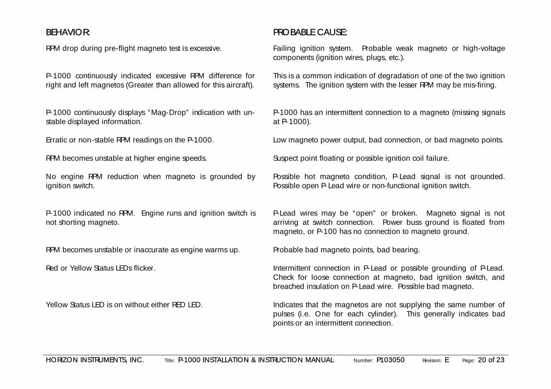
BEHAVIOR: PROBABLE CAUSE:
RPM drop during pre-flight magneto test is excessive. Failing ignition system. Probable weak magneto or high-voltagecomponents (ignition wires, plugs, etc.).
P-1000 continuously indicated excessive RPM difference forright and left magnetos (Greater than allowed for this aircraft).
This is a common indication of degradation of one of the two ignitionsystems. The ignition system with the lesser RPM may be mis-firing.
P-1000 continuously displays “Mag-Drop” indication with un-stable displayed information.
P-1000 has an intermittent connection to a magneto (missing signalsat P-1000).
Erratic or non-stable RPM readings on the P-1000. Low magneto power output, bad connection, or bad magneto points.
RPM becomes unstable at higher engine speeds. Suspect point floating or possible ignition coil failure.
No engine RPM reduction when magneto is grounded byignition switch.
Possible hot magneto condition, P-Lead signal is not grounded.Possible open P-Lead wire or non-functional ignition switch.
P-1000 indicated no RPM. Engine runs and ignition switch isnot shorting magneto.
P-Lead wires may be “open” or broken. Magneto signal is notarriving at switch connection. Power buss ground is floated frommagneto, or P-100 has no connection to magneto ground.
RPM becomes unstable or inaccurate as engine warms up. Probable bad magneto points, bad bearing.
Red or Yellow Status LEDs flicker. Intermittent connection in P-Lead or possible grounding of P-Lead.Check for loose connection at magneto, bad ignition switch, andbreached insulation on P-Lead wire. Possible bad magneto.
Yellow Status LED is on without either RED LED. Indicates that the magnetos are not supplying the same number ofpulses (i.e. One for each cylinder). This generally indicates badpoints or an intermittent connection.

HORIZON INSTRUMENTS, INC. Title: P-1000 INSTALLATION & INSTRUCTION MANUAL Number: P103050 Revision: E Page: 21 of 23
BEHAVIOR: PROBABLE CAUSE:
Red status LED flashed regularly. Check to see that the tachometer has not been accidentally shutdown. Quickly press and release the corresponding right or lefttachometer control buttons to see if the condition clears.
COMMON FAILURES OF IGNITION SYSTEM
Loose connection at magneto. Vibration of the engine can loosen the nuts/fittings where the P-lead terminates at the magneto.
Breached/Broken Insulation Heating/Cooling can deteriorate insulation on old wire, vibration can cause object to wear throughthe insulation (the firewall is a likely location).
Broken Ignition Switch Wafers/wipers inside the switch become loose or worn, debris (dust and dirt also) causes accidentalshorts.

HORIZON INSTRUMENTS, INC. Title: P-1000 INSTALLATION & INSTRUCTION MANUAL Number: P103050 Revision: E Page: 22 of 23
WARRANTYHorizon Instruments warrants this product to be free from defects in material or workmanship under normal use and service. HorizonInstruments’ obligation is limited to the repair or replacement of the defective product, which shall, within two years after shipment to theoriginal purchaser, be returned to Horizon Instruments, with transportation charges pre-repaired, and which upon examination shalldisclose to Horizon Instruments’ satisfaction to have been thus defective and not subject to issue, improper installation, abuse or accident.This warranty is in lieu of all other warranties, expressed or implied, and all other obligations or liabilities on Horizon Instruments’ part,and horizon Instruments neither assumes or authorized on any other person to assume any other liability in connection with the sale ofHorizon Instruments’ products.
In no event will Horizon Instruments be responsible for consequential damages resulting from the use of this product.
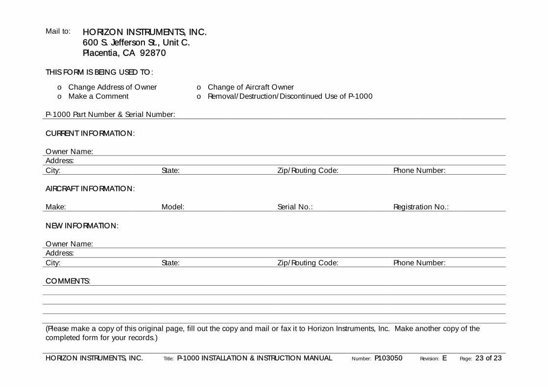
The following page contains a form you can use to register change of address, change of ownership, or to register a comment. It isincluded for your convenience and will help Horizon Instruments, Inc. better serve your needs in the future. Please photocopy the formfrom this manual, fill it out, and mail to the indicated address. Do no tear out the original, save it for the future use/owner.
The warranty is automatically registered to the original purchaser of the P-1000. If you change of ownership of the aircraft occurs, thefollowing form can be used to notify Horizon Instruments, Inc. of the change and keep the warranty in force.
HORIZON INSTRUMENTS, INC. Title: P-1000 INSTALLATION & INSTRUCTION MANUAL Number: P103050 Revision: E Page: 23 of 23
Mail to: HORIZON INSTRUMENTS, INC.600 S. Jefferson St., Unit C.Placentia, CA 92870
THIS FORM IS BEING USED TO:
o Change Address of Owner o Change of Aircraft Ownero Make a Comment o Removal/Destruction/Discontinued Use of P-1000
P-1000 Part Number & Serial Number:
CURRENT INFORMATION:
Owner Name:Address:City: State: Zip/Routing Code: Phone Number:
AIRCRAFT INFORMATION:
Make: Model: Serial No.: Registration No.:
NEW INFORMATION:
Owner Name:Address:City: State: Zip/Routing Code: Phone Number:
COMMENTS:
(Please make a copy of this original page, fill out the copy and mail or fax it to Horizon Instruments, Inc. Make another copy of thecompleted form for your records.)