installation instructionsdocuments.rasoenterprises.com/.../svis-lpg-installationmanual.pdf ·...
TRANSCRIPT
Technocarb Equipment (2004) Ltd. 4 - 30435 Progressive Way Abbotsford, BC, Canada V2T 6W3 Tel: (604) 854-6264 Fax: (604) 854-6802 Web: www.technocarb.com
Installation Instructions
General Motors 8.1 Sequential Vapor Injection (S.V.I.) System
7500/6500 Series Trucks 2003-2005 model year.
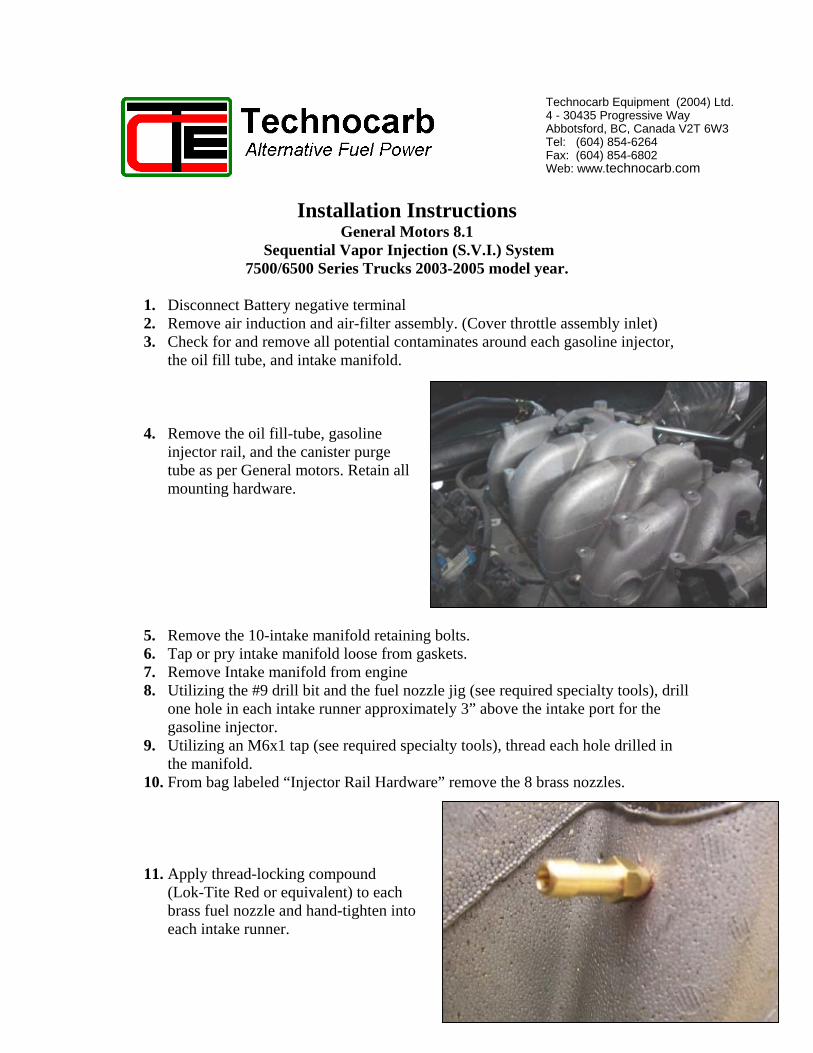
1. Disconnect Battery negative terminal 2. Remove air induction and air-filter assembly. (Cover throttle assembly inlet) 3. Check for and remove all potential contaminates around each gasoline injector,
the oil fill tube, and intake manifold.
4. Remove the oil fill-tube, gasoline injector rail, and the canister purge tube as per General motors. Retain all mounting hardware.
5. Remove the 10-intake manifold retaining bolts. 6. Tap or pry intake manifold loose from gaskets. 7. Remove Intake manifold from engine 8. Utilizing the #9 drill bit and the fuel nozzle jig (see required specialty tools), drill
one hole in each intake runner approximately 3” above the intake port for the gasoline injector.
9. Utilizing an M6x1 tap (see required specialty tools), thread each hole drilled in the manifold.
10. From bag labeled “Injector Rail Hardware” remove the 8 brass nozzles.
1
11. Apply thread-locking compound (Lok-Tite Red or equivalent) to each brass fuel nozzle and hand-tighten into each intake runner.

12. Tighten each fuel nozzle an additional 180 degrees (1/2 turn) with a 5/16” deep socket on a ¼” ratchet. (DO NOT apply excessive force to the nozzle)
13. Install gasoline rail and canister purge tube onto intake manifold as per General Motors and secure with original M6 hardware. Reconnect manifold vacuum source to fuel rail pressure regulator.
14. Install one ¼” fuel hose over each nozzle and secure with a #8 oetiker clamp.
NOTE: Crimp both ears on each clamp.
2
15. Install an Injector Rail Assembly onto the left side of the engine as shown. Secure with one M6 nut and flat-washer on to the rear mount of the gasoline injector rail.

16. Reinstall the oil fill tube assembly onto the manifold utilizing the original mounting hardware.
17. Slip one #8 Oetiker clamp over each ¼” fuel hose and route hoses to their corresponding injector outlet fittings. DO NOT CUT HOSES. Crimp each clamp on both ears to secure.
18. Install the other injector rail assembly onto the right-hand side of the intake manifold and secure with 2 M6 flat-washers and nuts provided. Slip one #8 oetiker clamp over each ¼” fuel hose. Route each hose to its corresponding injector and secure to outlet fitting by crimping both ears on the clamp.
19. From the length of 3/8” fuel hose provided, cut a 10.0” section and install onto the front fuel inlet of the Left-Side Injector Rail assembly. Secure hose with a #10 Oetiker Clamp
3

20. From the length of 3/8” fuel hose provided, cut an 11.0” section and install onto the front fuel inlet of the Right-Side Injector Rail assembly. Secure hose with a #10 Oetiker Clamp.
21. From the length of 3/8” fuel hose provided, cut an 18” section and install onto the rear fuel inlet of the Left-Side Injector Rail assembly. Secure hose with a #10 Oetiker Clamp.
22. From the length of 3/8” fuel hose provided, cut an 18” section and install onto the rear fuel inlet of the Right-Side Injector Rail assembly. Secure hose with a #10 Oetiker Clamp.
23. Replace the General Motors intake gasket, & install the intake manifold assembly onto the engine as per General Motors.
24. Connect the uppermost bracket of the Oil Fill Tube Assembly utilizing the original mounting hardware.
25. Lay the GM wiring harness in place
and install the M6 mounting bolt in the right front corner only. (Do not tighten at this point) Route the harness for the Left-Side Ignition coils under the right-hand side injector rail assembly bracket.
26. Install the Pressure Sensor Tee Assembly onto the left front mount of the intake manifold with the OEM harness clip for the left-side ignition coils/gasoline injector harness utilizing the original M6 mounting bolt. Torque to specifications.
27. Slip Oetiker clamps over the 3/8” fuel hoses from the front inlets of both injector rails. Trim hose lengths as required and connect to Tee Assembly as shown. Secure by crimping both ears of clamp.
28. Connect Canister purge solenoid, and left side ignition coils. (10-pin gray)
4

29. From the length of 3/8” fuel hose provided, cut a 24.0” section and install onto the fuel outlet of Pressure Regulator #1. Secure hose with a #10 Oetiker clamp.
30. From the length of 3/8” fuel hose
provided, cut a 16.0” section and install onto the fuel outlet of Pressure Regulator #2. Secure hose with a #10 Oetiker clamp.
31. From the length of 3/8” fuel hose provided, cut a 16.0” section and install onto the fuel outlet of Pressure Regulator #3. Secure hose with a #10 Oetiker clamp.
32. Mount the regulator bracket assembly as shown (on following page) to the tubular framing bracket for the air-filter housing located above the engine, utilizing the hardware in shipping bag labeled “Regulator Bracket Mounting Hardware”.
Torque to correct specification based on hardware size.
5

View from Under hood
6

33. From the packaging bag labeled “Rear Filter Bag” install one rear vapor filter with the TC3 clamp to the top of the intake bolts utilizing the M6 bolts to the main engine harness. The arrow on the filter should be pointing towards the rear of the engine compartment. In the event that the Technocarb label is missing, the metal filter is stamped ”IN” at one end.
34. Install the Left Rear Vapor filter with the TC3 clamp supplied to the top of the intake manifold with the original mounting hardware.
Note the filter clamp is UNDER the GM
harness clamp
35. Tighten M6 bolt on front of right side harness bracket and connect MAP sensor.
36. Route Pressure Differential Sensor (PDS), which is assembled to the Fuel Rail tee to the rear of the intake manifold. Mount to threaded boss of manifold with M6 bolt and flat-washer as illustrated. Ensure that the hosing from the Fuel rail Pressure Sensor is connected to the port labeled “P” on the P.D.S.
Note: The hosing from the rail pressure tee assembly to the P.D.S. operates at approximately 28-30 p.s.i. of LPG vapor.
KEEP AWAY FROM EXCESSIVE HEAT SOURCES. Exercise workmanship practices of a professional at all times.
7
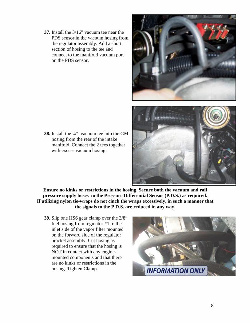
37. Install the 3/16” vacuum tee near the PDS sensor in the vacuum hosing from the regulator assembly. Add a short section of hosing to the tee and connect to the manifold vacuum port on the PDS sensor.
38. Install the ¼” vacuum tee into the GM hosing from the rear of the intake manifold. Connect the 2 tees together with excess vacuum hosing.
Ensure no kinks or restrictions in the hosing. Secure both the vacuum and rail pressure supply hoses to the Pressure Differential Sensor (P.D.S.) as required.
If utilizing nylon tie-wraps do not cinch the wraps excessively, in such a manner that the signals to the P.D.S. are reduced in any way.
39. Slip one HS6 gear clamp over the 3/8”
fuel hosing from regulator #1 to the inlet side of the vapor filter mounted on the forward side of the regulator bracket assembly. Cut hosing as required to ensure that the hosing is NOT in contact with any engine-mounted components and that there are no kinks or restrictions in the hosing. Tighten Clamp.
8

40. Cut and install a length of 3/8” fuel hose from the outlet side of the front vapor filter to the remaining hose-barb connector on the Pressure Sensor Tee Assembly. Install and crimp a #10 Oetiker clamp on the tee assembly hose-barb, and secure the filter side of the hose with an HS6 gear clamp.
Ensure that there are no kinks or restrictions in the fuel hose, and secure as required. Ensure that this hose is of sufficient length to absorb engine vibration as the filter is mounted to the chassis, while the tee assembly is mounted to the engine.
41. Install an HS6 gear-clamp over the 3/8” fuel hose from regulator #2. Route hose
to the inlet side of the left rear vapor filter, cut to length as required. Secure hose filter.
Ensure that there are no kinks or restrictions in the fuel hose, and secure as required. Ensure that this hose is of sufficient length to absorb engine vibration as the filter is mounted to the engine, while the regulator is mounted to the chassis.
42. Repeat step #33 for 3/8” fuel hose from Regulator #3 to the inlet of the right-side
rear vapor filter. 43. Connect the rear hose on the left injector rail assembly to the outlet side of the left
rear vapor filter and secure with an HS6 gear clamp 44. Connect the rear hose on the right injector rail assembly to the outlet side of the
right rear vapor filter and secure with an HS6 gear clamp.
45. From the shipping bag labeled “Liquid Filter Assembly” connect the brass fittings to the filter with a suitable thread sealant.
39. Mount the Liquid Filter assembly in a suitable location utilizing the TC2.5
mounting clamp. Use grade 5 or better hardware, 3/8” or larger. 40. Install a 3/8” LPG liquid hose from the regulator assembly’ s LPG lock-off
solenoid to the outlet side of the liquid filter. Secure as required.
9

41. Install a 3/8” LPG liquid hose from the inlet side of the liquid filter to the storage tank’s service valve. Secure as required.
42. Utilizing the shipping bagged labeled “SPK” install 5/8” coolant hosing from the regulator assembly to the vehicle’s heater core hoses. Ensure no kinks or restrictions and secure to chassis as required.
Pressure test cooling system as per General Motors
43. Remove the S.V.I. control module and main system wiring harness from their packaging.
44. Pull back the purple
lock mechanism on the harness main connector and plug the connector into the controller’s header connector as shown. The wiring harness from the harness connector should be on your right-hand side.
10

45. Apply slight pressure to the locking mechanism as shown. As the locking tab is inserted, the connector and header should be drawn together.
46. Apply moderate force until locking tab
is fully seated.
47. Mount the SVI controller in a vertical position with the harness connector on the bottom. Keep away from sources of excessive heat &/or electrical interference such as secondary ignition systems.
48. Disconnect General Motors connectors C1 & C2 from the OEM Powertrain Control Module. Remove the plastic covers to access the pin numbers.
49. Open the vehicle’s main wiring
harness from the General Motors PCM above the main fuse panel. Utilizing a high impedance multi-meter, isolate all the required wires required for system interfacing from the schesupplied. Solder and shrink tube all interfacing points.
11
matic
50. Upon successful completion of PCM wiring interfacing, reseal the factory wiring harness, and mount the system relays.
51. Reconnect PCM connectors (with shields properly reinstalled), as per GM. 52. Mount the Fuel Selector Switch in a suitable location in the dashboard. (Bi-Fuel) 53. Interface the remainder of the system as per the schematic. 54. Install air-filter assembly and induction system. 55. Connect MAF sensor. 56. Connect the vehicle’s battery. 57. Turn the ignition key to “ON” position, and check gasoline rail for leaks. 58. Turn engine off and load appropriate calibration file into the S.V.I. controller. 59. Start engine on gasoline and re-test gasoline fuel system for leaks. 60. Start engine and allow to idle until regulator assembly is heated from engine
coolant, and all air is purged from system. 61. Switch engine to propane, and perform final leak check on LPG system. 62. Test drive for proper system operation. 63. Ensure that at maximum engine speed that LPG rail pressure remains above 0.75
bar pressure. (From laptop interface) 64. Allow vehicle to idle in park. Turn off LPG supply to system. Allow the engine to
idle until all liquid propane in supply hose has been depleted. At such a time the SVIS controller will automatically switch back to gasoline operation, and the fuel selector switch will flash its lights and emit an audible noise.
65. Tap the selector switch once for gasoline operation and the switch should stop emitting its audible “BUZZ” and only the lower red LED light should be on signifying gasoline operation.
66. Perform a final leak test of the entire system.
12