installation guide - windows | doors | · pdf fileinstallation guide thank you for ... •...
TRANSCRIPT

INSTALLATION GUIDEK2. THE COMPLETE CONSERVATORY COMPANY
www.k2conservatories.com
K2 Conservatory Systems Ltd.Burnden Works, Burnden Road, Bolton, Lancashire, U.K. BL3 2RB
Tel: +44 (0)1204 554 554 Fax: +44 (0)1204 554 577
email: [email protected] www.k2conservatories.com
Freephone: 0800 195 2962 FM54162
S/C: IG2535 M/C: 3640/MAR07
K2 Conservatory Systems Ltd. is committed to continuous product development and manufacture. The product details given in this document are correct at time of publication,however K2 Conservatory Systems Ltd reserve the right to change specifications without notice. Customers should check with their supplier to ensure that they have the latest details.Copyright: K2 Conservatory Systems Ltd

Good Working Practice
Eaves Beam
Hips & Glazing Bars
Jack Rafters
Tie Bars
Glazing Panels
Ridge Top Cap
End Caps
Gutters
Internal Covers
Low Pitch Wallplate
Half Ridge Wallplate
Valleys
Quarter Boss
Special Ridges
Box Gutters
Bolster Bar
Lantern
03
05
09
11
12
14
18
21
23
24
27
28
30
33
34
35
38
39
PAGE NO.
CONTENTSINSTALLATION GUIDE
Thank you for purchasing your K2 Conservatory Roof System, which has been
prefabricated by one of our skilled craftsmen prior to delivery.
The following instructions will ensure an efficient and easy installation of your
conservatory roof. These instructions cover both glass and polycarbonate roofs
in 24/25mm and 35mm glazing.
A little time spent looking through the instructions prior to commencement will help to
give an understanding of the structure and the processes involved and will help to avoid
complications during assembly.
02
GOOD WORKING PRACTICEINSTALLATION GUIDE
For your safety when installing your
conservatory roof you should observe
the following points:
• Always use relevant ‘Personal Protective
Equipment’ (i.e. gloves, helmet, goggles,
safety shoes etc.) when erecting the
conservatory.
• All power tools used outdoors should
be 110 volt and connected through
a transformer.
• Window frames supporting the
conservatory roof should be installed
strictly in accordance with the system
manufacturer’s instructions.
• The use of a stable working platform
(scaffold or trestles) is highly
recommended for any conservatory
installation.
• Do not rely upon incomplete structures
to support your weight (either directly
or via ladders).
• Frequently check the window frames
for ‘square, line and plumb’ during
installation.
• Only use ‘Low Modulus, Neutral Cure’
Silicone for sealing PVCU to brickwork,
concrete or Lead.
• Check tightness of all fixings prior to
glazing roof or frames.
• Building sites (whether large or small)
are dangerous places. As such, the
general public (particularly children)
should be kept away until the installation
is complete.
• Remove all debris from the site upon
completion.
Tools required:
• Drill
• Screwdrivers
• Drill Bits
• Silicone Gun
• Step Ladder or Scaffold
• Spirit Level
• 8 and 10mm Nut Runner
03
* All measurements in this guide are in mm unless otherwise stated.

WINDOW FRAME PREPARATIONINSTALLATION GUIDE
EAVES BEAM PREPARATIONINSTALLATION GUIDE
N.B.
Apply a continuous bead of Low Modulus,
Neutral Cure Silicone to the front and rear
edges of the window frames.
Attach the Eaves Beam External Trim
to the Eaves Beam before positioning
onto the window frames.
Eaves Beam
The Eaves Beam External Trim
can now be used to locate the
Eaves Beam flush with the
outside of the frame.
Silicone
Silicone
Eaves Beam External Trim
0504

EAVES BEAM INSTALLATIONINSTALLATION GUIDE
EAVES BEAM INSTALLATIONINSTALLATION GUIDE
Apply a bead of Silicone to the cut faces.
Join and secure the
Eaves Beam together
using the Eaves Beam
Connector.
Silicone
Eaves Beam 6.35 x 38mm Self Tapping Screw
Eaves Beam Connector
140mm/160mm Eaves toFrame Fixing Bolts fitted at100 – 150mm from the jointof each Eaves Beam.
Fit the Eaves to Frame Fixing Bolts 100 – 150mm
from the joint of each Eaves Beam.
Silicone
70mm Frame 60mm Frame
N.B. Before connecting the Eaves Beam, ensure all Bolt Carriers are in position.
0706

EAVES BEAM INSTALLATIONINSTALLATION GUIDE
HIP & GLAZING BAR INSTALLATIONINSTALLATION GUIDE
Once the Eaves to Frame Fixing Bolts have been secured, the Eaves Beam should be further
fixed to the window frames using M5 x 60mm screws at 600mm centres (if the Eaves Beam
exceeds 3 metres in length an additional Eaves to Frame Fixing Bolt should be fitted centrally).
Eaves to Frame Fixing Bolt
M5 x 60mm Self TappingScrews at 600mm centres
Place the Ridge centrally on an access tower or platform at approximately the required height.
Loosely connect the Bar (P1 or P10) to the Eaves Beam and rest it on the Ridge body.
Do the same with the Transom nearest to the Boss End. (P3 or P8). Repeat on the opposite side.
Slowly lift and tilt the Ridge to allow the Glazing Bars to locate on the Ridge Wing (this may
require two people depending on the Ridge length). The Ridge is now self-supporting. If the
Glazing Bars are not not in the correct position, reposition them now. Now, fit the Hip Bars in
sequence as stated on the paperwork followed by all remaining Transoms. Finally, tighten all the
Glazing Bar Nuts whilst constantly checking that the Ridge is still level.
P10
P9
P8
P7
P5 P6
P1
P2
P3
P4
0908

GLAZING BAR INSTALLATIONINSTALLATION GUIDE
JACK RAFTER INSTALLATIONINSTALLATION GUIDE
Wall End Bars should now be secured to the wall using appropriate fixings within 100 – 150mm
of the Ridge and the Eaves Beam and no more than 600mm apart. N.B. Fixings must be of
suitable length and diameter for the substrate used. Always refer to the fixing manufacturer for
recommendations. If not already completed, chase out the Lead flashing at this stage.
Wall End Bar
Lead flashing
Jack Rafter Bar
Slide the Bottom Cap up, attach the nut
and tighten.
To seal the joint, apply a continuous bead of
Silicone between the Hip and the Jack Rafter.
Use Low Modulus,Neutral Cure Siliconeto seal the jointbetween the Hip andJack Rafter.
Silicone
Jack Rafter Capping
Hip Bar
Hip Bar
Nut
PivotBolt
Jack Rafter Arm
Bottom Cap
Hip Capping
Slide Bottom Cap back to allow arm to hook
on the Bolt.
If a Wallbar of the type shown is being used, install the Lead Flashing.
1110

TIE BAR INSTALLATIONINSTALLATION GUIDE
Attach the Tie Bar Centre Boss Covers.
3 Way
5 Way
TIE BAR INSTALLATIONINSTALLATION GUIDE
Cut and attach all horizontal Threaded
Bars, screwing one end into a Clevis
fixing or into the Eaves Beam,
keeping Tie Bar Boss Ring central.
Loosely assemble onto the Tie Bar
Centre Boss and cut all the remaining
Tie Bar covers to length and install.
Drill the Ridge Centre Spacer
using a 10mm drill bit top
and bottom. Attach a nut
to vertical Threaded Bar and
lower through the Ridge
Centre. Drill the Undercladding
to slide over the Tie Bar.
Cut the vertical Threaded Bar to
length and attach the Tie Bar
Centre Boss.
Clevis Fixing
Eaves Beam
Box Gutter Fixing
RidgeUndercladding
Eaves Beam Fixing
Box Gutter
Clevis
PVC Conduit
Tie Bar Centre Boss
Nut
Ridge Centre
VerticalThreaded Bar
1312

INSTALLING GLAZING PANELSINSTALLATION GUIDE
Each panel has an identification letter which
corresponds to the location plan. Remove the
protective film ensuring the external face of
the panel is to the outside, centralise the
panel and push firmly between the Ridge
Cloaking Trims.
Eaves Closure Backing Tape
Protective Film
G1
G2
G9
G8
G3 G7
G4 G6
G5
IdentificationLetter
Glazing Bar
Glazing Installation Plan
Remove the remainder of the Eaves
Closure backing tape and press the panel
down onto the Eaves Closure.
PREPARING GLAZING PANELSINSTALLATION GUIDE
Before fitting each Glazing
Panel, pull back a small piece
of the backing cover of the
Eaves Closure Tape as shown.
Do not remove completely
at this stage.
Eaves Beam Closure
Remove the Polycarbonate End
Trim and apply a continuous
bead of Silicone along its entire
length in the position shown
and replace.
Polycarbonate End Trim
Backing cover
Silicone
1514

INSTALLING THE GLAZING PANELSINSTALLATION GUIDE
Foam Bung
Tear along the perforationsfor roofs using theStandard Ridge.
Bend and insert the Foam Bung into the void
on the Boss End.
Low Modulus, NeutralCure Silicone
Ensure that the last Victorian or Georgian
Hip Cappings are mitred into the side of the
cloaking Trims and then seal with Silicone.
Apply a bead of Silicone around each Glazing
Bar Top Capping.
INSTALLING GLAZING PANELSINSTALLATION GUIDE
Prior to fitting the PVC Top Cappings, lubricate the
gaskets with a Silicone spray and knock down
every 300mm using a nylon mallet. Aluminium Top
Cappings do not require lubrication, but should be
installed with a rubber mallet.
Nylon Mallet
Top Caps must be
located as shown along
their entire length.
Silicone Spray
1716
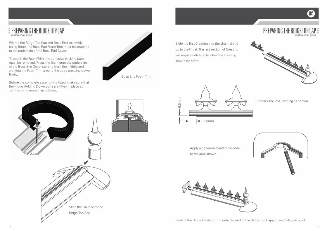
PREPARING THE RIDGE TOP CAPINSTALLATION GUIDE
Apply a generous bead of Silicone
to the area shown.
Push fit the Ridge Flashing Trim onto the end of the Ridge Top Capping and Silicone point.
PREPARING THE RIDGE TOP CAPINSTALLATION GUIDE
Slide the Finial onto the
Ridge Top Cap.
Cut back the last Cresting as shown.
1918
Prior to the Ridge Top Cap and Boss End assemblybeing fitted, the Boss End Foam Trim must be attachedto the underside of the Boss End Cover.
To attach the Foam Trim, the adhesive backing tapemust be removed. Press the foam onto the undersideof the Boss End Cover starting from the middle andworking the Foam Trim around the edge pressing downfirmly.
Before the complete assembly is fitted, make sure thatthe Ridge Holding Down Bolts are fitted in place atcentres of no more than 500mm.
Boss End Foam Trim
Slide the first Cresting into the channel and
up to the Finial. The last section of Cresting
will require notching to allow the Flashing
Trim to be fitted.
6.5m
m
35mm

INSTALLING END CAPSINSTALLATION GUIDE
M4 x 25mm Self TappingScrew for End Caps
End Caps for Polycarbonate
End Caps for Glass
N.B.
When fitting a Wallbar to the
wall, the End Cap will require
cutting down.
Additional Glass Plate
INSTALLATION OF RIDGE TOP CAPINSTALLATION GUIDE
Align the Ridge Top Cap with
the Aluminium Ridge Spacers
and push into place.
Screw Nuts and square washer
onto the Ridge Holding Down
Bolts and finger tighten.
Dress Lead over the top
of the flashing Trim
behind the Cresting.
Ridge Holding Down Bolt
NylonNut
Cresting Flashing Trim Lead Flashing
Ridge Top Cap
Ridge Spacers
2120

INSTALLING THE GUTTERSINSTALLATION GUIDE
Stop End Gutter Union Stop End Outlet
Clip Detail
INSTALLING END CAPSINSTALLATION GUIDE
Trim and attach the Eaves Beam End Cap as shown.
Attach the Wallbar Fascia Trim.
Attach the Half Ridge Wallplate End Caps.
Eaves Beam End Cap
Wallbar Fascia Trim
35o
30o
25o
20o
15o
10o
5o
2322

FITTING INTERNAL EAVES COVERSINSTALLATION GUIDE
Internal Eaves Cover Joint
For 70mm frames the use of an Eaves Beam Packer is required.
Eaves Beam Packer
60mm Frame
70mm Frame
500
INSTALLATION OF BOSS END INTERNAL COVERINSTALLATION GUIDE
Offer up the Internal Boss Cover and
trim to the correct pitch if necessary.
M4 x 25mmSelf Tapping Screwand Cover Cap
Internal Ridge Cover
Screw the Internal Boss Cover into the
‘L’ shape bracket.
Clip on the Internal Ridge Cover.
30o
25o
20o30
o
25o
20o
‘L’ Shape Bracket
2524

LOW PITCH WALLPLATE 5 -10o
INSTALLATION GUIDE
N.B.
When installed, the Lead
Flashing will overlap the
End Cap.
Lead Flashing
5-10oLow
Pitch Wallplate
Low Pitch Wallplate End Cap
DECORATIVE EAVES BEAM COVERINSTALLATION GUIDE
Insert the Decorative Moulding into the Internal Cover
as shown above. 60mm Frame
70mm Frame
Corner CoverDecorative Eaves Beam Cover
EavesBeamPacker
2726

INSTALLATION OF HALF RIDGE WALLPLATEINSTALLATION GUIDE
Flashing Section
Half Ridge WallplateTop Capping
Prior to attaching the Half Ridge Top Capping and Flashing section, chase out the wall
for Lead Flashing. Install the Glazing Panels and Top Cappings (see section 2 ‘Installing
Glazing Panels’).
Window frame
Internal Half RidgeUndercladding
Cut and install the Half Ridge
Wallplate Undercladding.
INSTALLATION OF HALF RIDGE WALLPLATEINSTALLATION GUIDE
The Half Ridge Wallplate
and Variable Wing should be
offered up to the house wall
ensuring that the aluminium
is flush with the outside face
of the Gable Frames.
The Gable Frames should
be notched as shown.
Remove the Variable Wing and
secure the Half Ridge
Wallplate to the wall using
suitable fixings at 600mm
centres.
Replace the Variable Wing and install the Glazing Bars and Wall/Starter Bars. Prior to attaching
the Wall/Starter Bars, apply a continuous bead of Silicone sealant to the top of the window
frames/ Firrings (as shown). Place the Wall/Starter Bar onto the Firrings ensuring the outside
edge of the Wall/Starter Bar is 2mm proud of the window frames or 4.5mm proud of the K2 Firrings.
Fix the Wall/Starter Bar to the window frame/Firring at 500mm centres.
Glazing Bar
Fix at 500mmcentres
Wall /Starter Bar
Ridge Wing Half Ridge Wallplate
Gable Frame
70mm FrameWindow Frame
2928
600
21

VALLEY INSTALLATIONINSTALLATION GUIDE
Offer the Valley up to the roof and bolt
to the main Ridge and Wallplate
Bolt the Valley to the Eaves Beam ensuring Eaves
Closure Tape is adhered to both Valley Wings.
Valley Glazing Bars should now be bolted into position. Prior to glazing, peel back a small piece of
protective tape as shown.
Cut the Valley Top Capping to length. Note
the Valley Top Capping will require scribing
into the joint between the Ridge Top Cap and
the Half Ridge Top Cap. The Flashing Trim
will also need trimming as shown.
Welded Half Ridge/Ridge Top Capping
Flashing Trim
EavesClosureTape
Valley Glazing Bar
MainRidge
HalfRidge
Wallplate
Valley
Poly End Trim
Valley Top CapGlazing Bar Top Cap
Double SidedTape
When assembling a ‘P’ shaped roof,
assemble as much of the Victorian/
Georgian as possible, levelling the main
Ridge and tightening the Glazing Bars.
Offer up the Half Ridge Wallplate (including the Ridge Wing) to the house wall and position to the
side of the main Ridge. It is important to ensure that the top of both Bottom Cloaking Trims
(main Ridge and Variable Wing) are level to each other.
This is usually completed by locating several Glazing Bars on to the Lean-to section (do not
tighten Glazing Bars at this time). Mark the position of the Wallplate on the wall, remove the
Glazing Bars and Ridge Wing and fix the Wallplate to the house wall using suitable Anchor
fixings.
Wallplate Half Ridge
500 max.
Anchor fixings
Variable Wing
BottomCloaking Trim
Bottom Cloaking Trim
Half Ridge Wallplate
VALLEY INSTALLATIONINSTALLATION GUIDE
3130

QUARTER BOSSINSTALLATION GUIDE
Half RidgeWallplate
Foam Bung
RidgeWing
Silicone
Fix the Half Ridge Wallplate and
Aluminium Quarter Boss End to the
house wall using suitable fixings.
Install the Ridge Wing, Transoms, Wallbars
and glazing (see previous section). Seal the
Top Caps and glazing to the Foam Bung
using Silicone sealant.
Install the External Quarter Boss
Cover. Fix the Boss Cover through the
upstand using suitable Fixings. Seal
Cover against Half Ridge Top Cap.
This face to be trimmed on site.
Install the Internal Quarter Boss End and
Wallplate Undercladding as shown.
QuarterBoss End
InternalQuarterBoss EndCover
FlashingSection
Silicone
Fixings
Half RidgeTop Cap
VALLEY INSTALLATIONINSTALLATION GUIDE
Fit the Valley End Cap.
Mitre the Valley Undercladdings into the
Eaves Beam.
Scribe the Valley Undercladdings into the Half
Ridge Wallplate and Ridge Undercladdings.
3332
External Quarter Boss Cover. This face
to be trimmed to suit angle of Wallplate
and angle of glazing material.

BOX GUTTER PREPARATIONINSTALLATION GUIDE
Ensure the Braces are positioned at maximum centres of 600mm.
Remove the nib (locally) to allow the
Box Gutter to sit flush on top of the
window frames.
Self Tapping Screwsat 600mm centres
Eaves Beam
Box Gutter
SPECIAL RIDGESINSTALLATION GUIDE
‘L’ Ridge Joint Cover
Ridge Top Cap Jointer
‘T’ Ridge Joint Cover
Trim the underside of the Ridge Top Cap
back by 20mm and push fit into the
Jointer as shown.
3534

BOX GUTTER ADAPTOR INSTALLATIONINSTALLATION GUIDE
Ensure both the Box Gutter and Adaptor fit.
If necessary, Trim the Adaptor as shown.
Attach the Stop End.
Thoroughly clean the inside of the Box
Gutter at the position of the Adaptor.
Apply a continuous bead of Silicone to the
sides and bottom face of the Box Gutter and
insert the Adaptor. Ensure all excess Silicone
has been removed and once again clean the
aluminium with wire wool, ensuring the
surface is clean and dry.
Low Modulus,Neutral Cure Silicone
Box Gutter
Stop End
21mm
Universal BoxGutter Adaptor
Trim
Remove the backing of the special Sealing
Tape. Gently heat the Sealing Tape and
aluminium of the Box Gutter. Position the
Tape centrally over the joint, pressing
firmly across the Adaptor and Box Gutter.
Ensure no air pockets are present, working
well into the corners and sides.
BOX GUTTER INSTALLATIONINSTALLATION GUIDE
The Box Gutter should sit flush with the end of the window frames and be bedded on to two
beads of Silicone (as the Eaves Beam).
Ensure the Box Gutter is level and fix through the Braces (at 600mm) into the house wall.
Eaves Beams should now be joined using Connectors (see page 6), then bolted and screwed
to the window frames beneath.
Using a heat gun, warm the aluminium
to remove any moisture that may prevent
good adhesion.
3736

LANTERNINSTALLATION GUIDE
Glazing Bar
Eaves Beam
Lantern Ridge
Internal Cover
window frames
Half Ridge Top Cap
BOLSTER BAR INSTALLATIONINSTALLATION GUIDE
The Bolster Bar is suitable for Heavy Duty
Transoms and Victorian and Georgian Hips.
Fit the Bolster Bar Cover and End Cap as
shown prior to installing the Glazing Bar.
Secure the Bolster Bar End Caps using the
Screw and Plug (supplied).
N.B. The Bolster Bar Covers will require
notching at the position of Jack Rafters.
BolsterBarCapping
Bolster BarEnd Cap
Screw
Plug
BolsterBar
3938