installation guide valve station icf...
TRANSCRIPT
Installation Guide
Valve StationICF 20-40
© Danfoss A/S (AC-MCI/MWA), 2012-12 DKRCI.PI.FT0.C4.02 / 520H5450 1
027R
9782
027R
9782
ICM
ICM
ICM
ICM
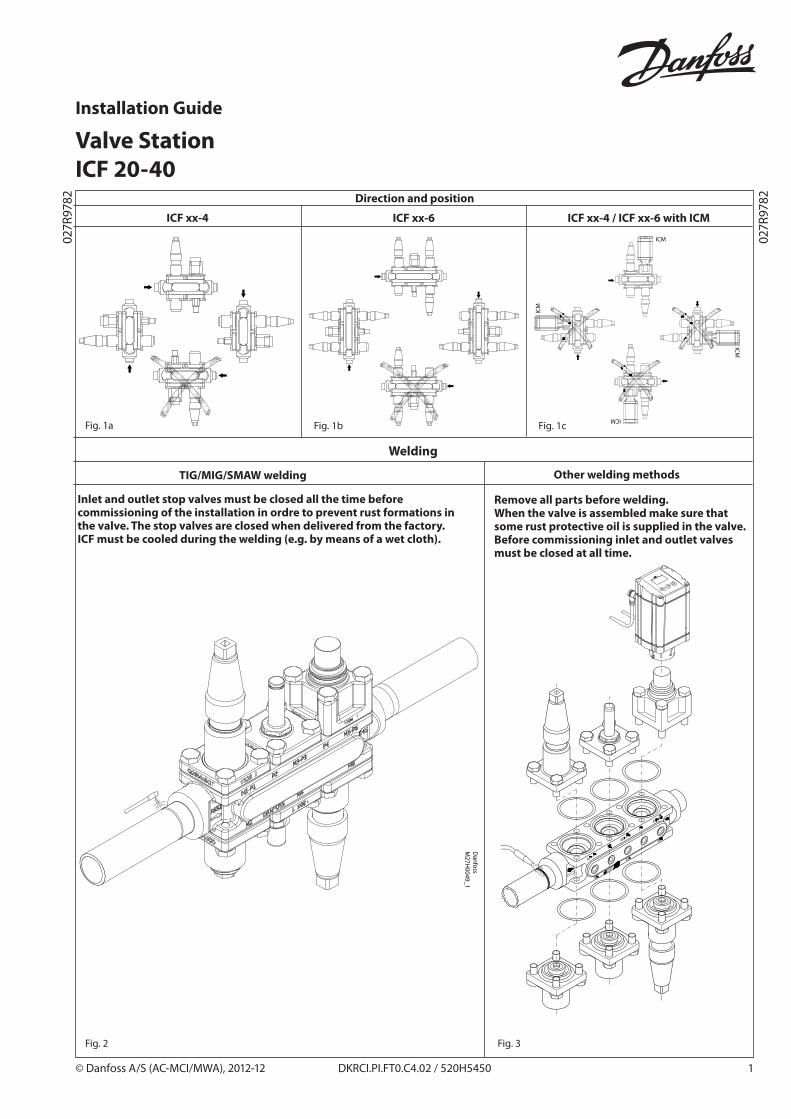
Direction and position
ICF xx-4 ICF xx-6 ICF xx-4 / ICF xx-6 with ICM
Welding
TIG/MIG/SMAW welding Other welding methods
Remove all parts before welding.When the valve is assembled make sure that some rust protective oil is supplied in the valve.Before commissioning inlet and outlet valves must be closed at all time.
Fig. 1a Fig. 1b Fig. 1c
Fig. 2 Fig. 3
Dan
foss
M27H
0049_1
Inlet and outlet stop valves must be closed all the time before commissioning of the installation in ordre to prevent rust formations in the valve. The stop valves are closed when delivered from the factory.ICF must be cooled during the welding (e.g. by means of a wet cloth).
2 DKRCI.PI.FT0.C4.02 / 520H5450 © Danfoss A/S (AC-MCI/MWA), 2012-12
Service and maintenance
Tightening torques
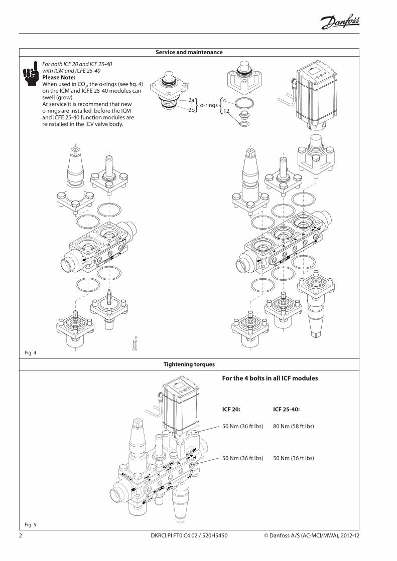
Fig. 4
Fig. 5
ICF 20: ICF 25-40:
50 Nm (36 ft lbs) 80 Nm (58 ft lbs)
50 Nm (36 ft lbs) 50 Nm (36 ft lbs)
For both ICF 20 and ICF 25-40 with ICM and ICFE 25-40Please Note:When used in CO2, the o-rings (see fig. 4) on the ICM and ICFE 25-40 modules can swell (grow).At service it is recommend that new o-rings are installed, before the ICM and ICFE 25-40 function modules are reinstalled in the ICV valve body.
2a
2b
4
12o-rings
For the 4 bolts in all ICF modules
© Danfoss A/S (AC-MCI/MWA), 2012-12 DKRCI.PI.FT0.C4.02 / 520H5450 3
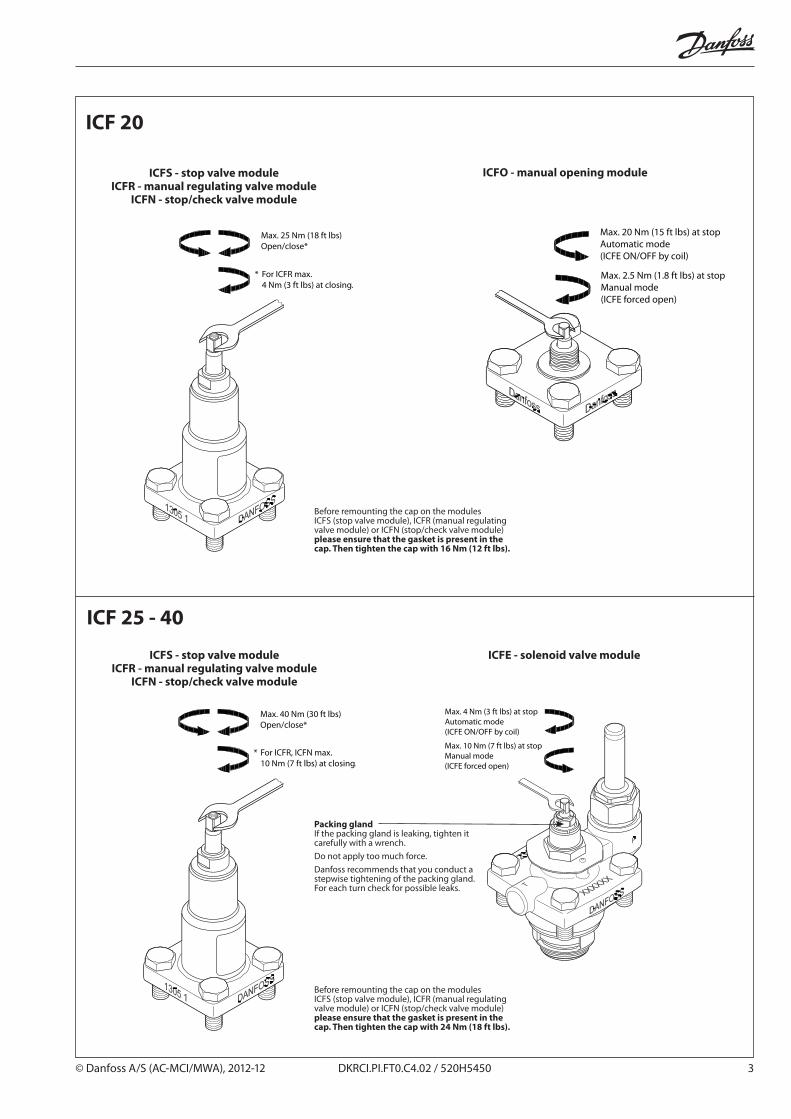
ICF 20
ICFS - stop valve moduleICFR - manual regulating valve module
ICFN - stop/check valve module
ICF 25 - 40
ICFS - stop valve moduleICFR - manual regulating valve module
ICFN - stop/check valve module
ICFO - manual opening module
ICFE - solenoid valve module
Packing glandIf the packing gland is leaking, tighten it carefully with a wrench. Do not apply too much force. Danfoss recommends that you conduct a stepwise tightening of the packing gland. For each turn check for possible leaks.
Before remounting the cap on the modules ICFS (stop valve module), ICFR (manual regulating valve module) or ICFN (stop/check valve module) please ensure that the gasket is present in the cap. Then tighten the cap with 16 Nm (12 ft lbs).
Before remounting the cap on the modules ICFS (stop valve module), ICFR (manual regulating valve module) or ICFN (stop/check valve module) please ensure that the gasket is present in the cap. Then tighten the cap with 24 Nm (18 ft lbs).

4 DKRCI.PI.FT0.C4.02 / 520H5450 © Danfoss A/S (AC-MCI/MWA), 2012-12
Operating the manual opener on ICFE 20H solenoid valve module
Operating the manual opener on ICFE 25 solenoid module
To force open the solenoid by the manual stem turn it counter clockwise full way up. (Manual mode)To operate the solenoid in automatic mode, turn the manual stem clockwise until the locking ring stops. Do not force the spindle further. If the locking ring is damaged or removed the spindle will start to leak.The valve cannot be forced closed by the manual stem.
ICFE 25-40 solenoid valve module
Locking ring
Turn spindle counter clockwise to open
Remove the cap on the side of the ICFE 20HAt 9 o’clock position the manual opener is disabled (not active)To force the ICFE 20H solenoid to open use a 5 mm Allen key and turn it clockwise to 3 o’clock position.
Manual opener disabled Position for forced open
© Danfoss A/S (AC-MCI/MWA), 2012-12 DKRCI.PI.FT0.C4.02 / 520H5450 5
Module location
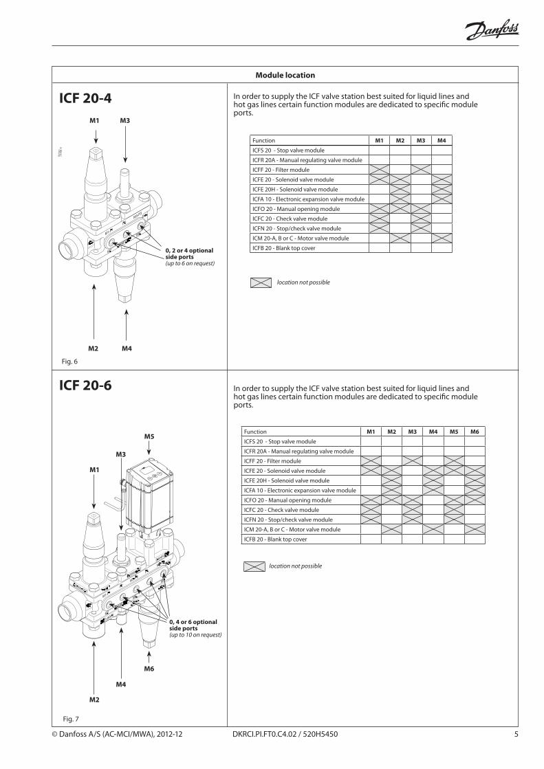
ICF 20-4
0, 2 or 4 optional side ports(up to 6 on request)
Fig. 6
In order to supply the ICF valve station best suited for liquid lines and hot gas lines certain function modules are dedicated to specific module ports.
Function M1 M2 M3 M4
ICFS 20 - Stop valve module
ICFR 20A - Manual regulating valve module
ICFF 20 - Filter module
ICFE 20 - Solenoid valve module
ICFE 20H - Solenoid valve module
ICFA 10 - Electronic expansion valve module
ICFO 20 - Manual opening module
ICFC 20 - Check valve module
ICFN 20 - Stop/check valve module
ICM 20-A, B or C - Motor valve module
ICFB 20 - Blank top cover
location not possible
ICF 20-6 In order to supply the ICF valve station best suited for liquid lines and hot gas lines certain function modules are dedicated to specific module ports.
Function M1 M2 M3 M4 M5 M6
ICFS 20 - Stop valve module
ICFR 20A - Manual regulating valve module
ICFF 20 - Filter module
ICFE 20 - Solenoid valve module
ICFE 20H - Solenoid valve module
ICFA 10 - Electronic expansion valve module
ICFO 20 - Manual opening module
ICFC 20 - Check valve module
ICFN 20 - Stop/check valve module
ICM 20-A, B or C - Motor valve module
ICFB 20 - Blank top cover
location not possible
0, 4 or 6 optional side ports(up to 10 on request)
Fig. 7
6 DKRCI.PI.FT0.C4.02 / 520H5450 © Danfoss A/S (AC-MCI/MWA), 2012-12
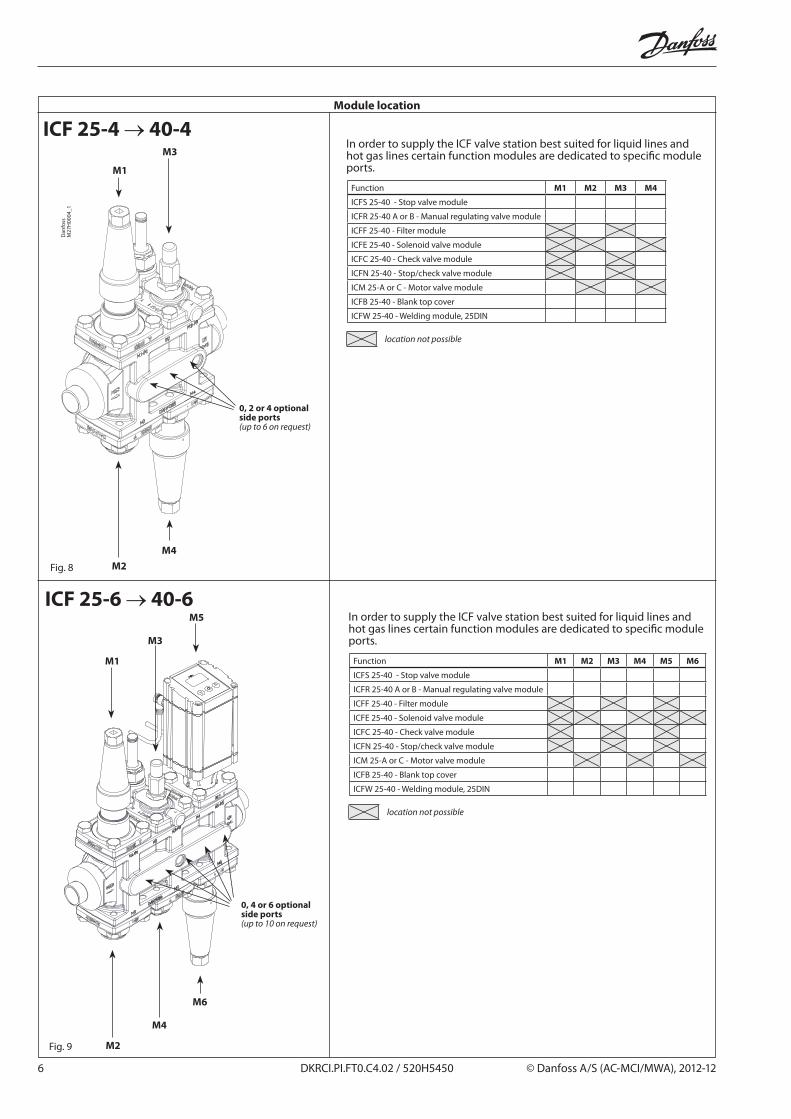
ICF 25-4 → 40-4
ICF 25-6 → 40-6
Module location
Function M1 M2 M3 M4 M5 M6
ICFS 25-40 - Stop valve module
ICFR 25-40 A or B - Manual regulating valve module
ICFF 25-40 - Filter module
ICFE 25-40 - Solenoid valve module
ICFC 25-40 - Check valve module
ICFN 25-40 - Stop/check valve module
ICM 25-A or C - Motor valve module
ICFB 25-40 - Blank top cover
ICFW 25-40 - Welding module, 25DIN
location not possible
In order to supply the ICF valve station best suited for liquid lines and hot gas lines certain function modules are dedicated to specific module ports.
Function M1 M2 M3 M4
ICFS 25-40 - Stop valve module
ICFR 25-40 A or B - Manual regulating valve module
ICFF 25-40 - Filter module
ICFE 25-40 - Solenoid valve module
ICFC 25-40 - Check valve module
ICFN 25-40 - Stop/check valve module
ICM 25-A or C - Motor valve module
ICFB 25-40 - Blank top cover
ICFW 25-40 - Welding module, 25DIN
location not possible
In order to supply the ICF valve station best suited for liquid lines and hot gas lines certain function modules are dedicated to specific module ports.
Fig. 8
Fig. 9
Dan
foss
M27
H00
04_1
0, 2 or 4 optional side ports(up to 6 on request)
0, 4 or 6 optional side ports(up to 10 on request)
© Danfoss A/S (AC-MCI/MWA), 2012-12 DKRCI.PI.FT0.C4.02 / 520H5450 7
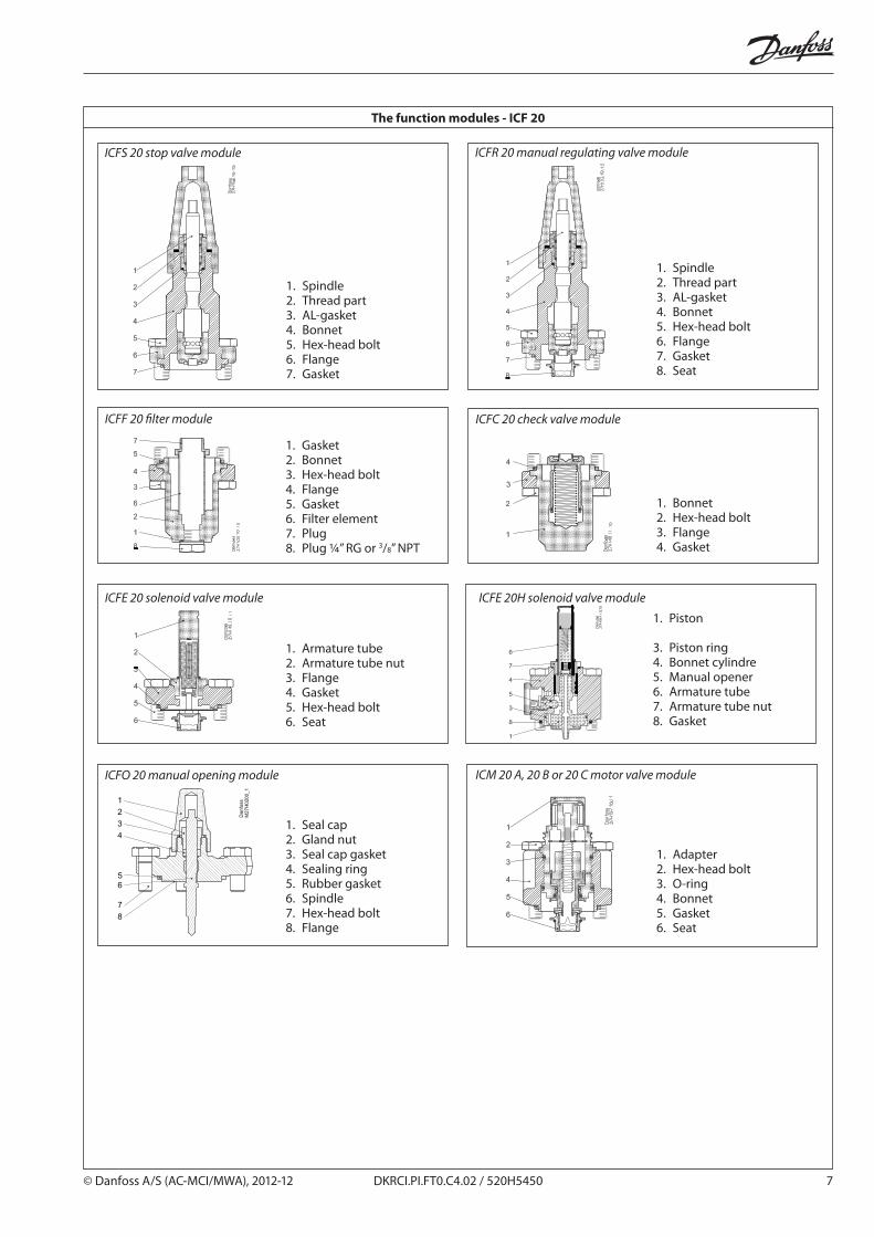
ICFF 20 filter module
ICFS 20 stop valve module
1. Spindle2. Thread part3. AL-gasket4. Bonnet5. Hex-head bolt6. Flange7. Gasket
1. Gasket2. Bonnet3. Hex-head bolt4. Flange5. Gasket6. Filter element7. Plug8. Plug 1/4” RG or 3/8” NPT
ICFE 20 solenoid valve module
1. Armature tube2. Armature tube nut3. Flange4. Gasket5. Hex-head bolt6. Seat
ICFO 20 manual opening module
1. Seal cap2. Gland nut3. Seal cap gasket 4. Sealing ring5. Rubber gasket 6. Spindle7. Hex-head bolt 8. Flange
ICFR 20 manual regulating valve module
1. Spindle2. Thread part3. AL-gasket4. Bonnet5. Hex-head bolt6. Flange7. Gasket8. Seat
ICFC 20 check valve module
1. Bonnet2. Hex-head bolt3. Flange4. Gasket
ICM 20 A, 20 B or 20 C motor valve module
1. Adapter2. Hex-head bolt3. O-ring4. Bonnet5. Gasket6. Seat
The function modules - ICF 20
ICFE 20H solenoid valve module
1. Piston
3. Piston ring4. Bonnet cylindre5. Manual opener6. Armature tube7. Armature tube nut8. Gasket

8 DKRCI.PI.FT0.C4.02 / 520H5450 © Danfoss A/S (AC-MCI/MWA), 2012-12
ICFA 10 Electronic expansion valve
1. Armature tube2. Armature tube nut3. Hex-head bolt4. Flange5. Gasket6. Adaptor
ICFN 20 stop/check valve module
1. Spindle2. Thread part3. AL-gasket4. Bonnet5. Hex-head bolt6. Flange7. Gasket
ICFB 20 blank top cover module
1. Hex-head bolt2. Flange3. Gasket
ICFF 20E extended filter module
1. Dirt protection plug2. Bonnet3. Hex-head bolt M12x804. Flange5. Gasket6. Filter element7. Plug 3/8” NPT8. Filter adaptor
ICFS 25-40 stop valve module
1. Spindle2. Thread part3. O-ring4. Bonnet5. Hex-head bolt6. Flange7. Gasket
ICFR 25- 40 A or B manual regulating valve module
1. Spindle2. Thread part3. O-ring4. Bonnet5. Hex-head bolt6. Flange7. Gasket
The function modules - ICF 20

© Danfoss A/S (AC-MCI/MWA), 2012-12 DKRCI.PI.FT0.C4.02 / 520H5450 9
ICFF 25-40 filter module
1. Al gasket2. Bonnet3. Hex-head bolt4. Flange5. Gasket6. Filter element7. Plug 1/4” RG or 3/8” NPT
ICFE 25-40 solenoid valve module
1. Armature tube2. Armature tube nut3. Bonnet4. Gasket5. Hex-head bolt6. Seat
ICM 25 A or 20 B motor valve module
1. Adapter2. Hex-head bolt3. O-ring4. Bonnet5. Gasket6. Seat
ICFN 25-40 stop/check valve module
1. Spindle2. Thread part3. O-ring4. Bonnet5. Hex-head bolt6. Flange7. Gasket
ICFB 25-40 blank top cover module
1. Hex-head bolt2. Flange3. Gasket
ICFC 25-40 check valve module
1. Bonnet2. Hex-head bolt3. Flange4. Gasket
ICFW 25-40 Welding module 25 DIN
1. Hex-head bolt2. Flange3. Gasket4. Weld connection
1
2
3
4
5
6
The function modules - ICF 25-40
ICFF 25-40E extended filter module
1. Dirt protection plug 3/8” NPT2. Bonnet3. Hex-head bolt M12x1404. Flange5. Gasket6. Filter element7. Plug 3/8” NPT

10 DKRCI.PI.FT0.C4.02 / 520H5450 © Danfoss A/S (AC-MCI/MWA), 2012-12
ENGLISH
Installation
RefrigerantsApplicable to HCFC, non flammable HFC, R717 (Ammonia) and R744 (CO2).
The use of ICF valve stations with flammable hydrocarbons is not recommended.
The ICF is only recommended for use in closed circuits. For further information please contact Danfoss.
Temperature range–60/+120°C (–76/+248°F)
Pressure rangeThe ICF is designed for a max. working pressure of 52 bar g (754 psi g).
Technical dataThe ICF can be used in suction, liquid, hotgas and liquid/vapor lines. The ICF are available with 4 or 6 function modules. The ICF regulates the flow of the medium by modulation or on/off function, depending on function modules installed on the ICF.
Regulating rangeDependent on the chosen type and combination of modules installed in the valve.
InstallationThe ICF must be installed according to fig. 1. The ICF must be installed with the arrow in the direction of the flow).
The ICF will be delivered with all the function modules fully assembled. The modules can be taken off for service or inspection and may be rotated 4 x 90° in relation to the valve body upon installation.
The ICF may be fitted with a spindle for manual opening of the solenoid valve.
The ICF is designed to withstand a high internal pressure. However, the piping system should be designed to avoid liquid traps and reduce the risk of hydraulic pressure caused by thermal expansion.
It must be ensured that the ICF is protected from pressure transients like “liquid hammer” in the system.
Welding The ICF valve station can be welded by using either TIG/MIG/SMAW welding (fig. 2) or gas welding (fig. 3).
Attention!It is not necessary to remove any of the modules before TIG/MIG/SMAW welding; however, it must be ensured that the valve is cooled during the welding ( e. g. by wet cloth) and that the ICF is protected against weld splatter. Inlet and outlet stop valves must be closed all the time before commissioning in order to protect ICF against rust formations.
The ICF valves are delivered with closed stop valves.During Gas welding the modules must be removed.Avoid welding debris and dirt in the valve body and the function module. The housing must be free from stresses (external loads) after installation. The ICF must not be mounted in systems where the outlet side of the ICF is open to atmosphere. The outlet side of the ICF must always be connected to the system or properly capped off, for example with a welded-on end plate.
Surface protection and identificationThe external surface is zinc-chromated to provide corrosion protection according to EN 12284:2003 8.13. The Zinc-Chromatization does not cover the welding connections. After installation has been completed the external surface of the valve must be protected against corrosion with a suitable top coating.Protection of the ID label when painting the ICF is recommended.
Precise identification of the ICF is made via the ID label on each of the 4 or 6 function modules.
Maintenance ServiceThe ICF valve stations are easy to service. Do not open the ICF while the it is still under pressure.
Debris blocking the bolt hole will need cleaning. Upon opening and removal of the function modules:- Check that the O-rings on the function module has not been damaged. A valve with a damaged o-ring might not modulate according to the specification.
For both ICF 20 and ICF 25 - 40 with ICM
Please Note: When used in CO2, the o-rings (see fig.4) on the ICM and ICFE 25-40 modules can swell (grow). At service it is recommend that new o-rings are installed, before the ICM function module is reinstalled in the ICF valve body.
- Check that the piston and cylinder is free of scratches and look for wear marks. If the wear is excessive the function module should be replaced to prevent false pilot signal around the piston ring.- Check that the movement of the cylinder and valve seat is free and with low friction.- If the teflon valve plate has been damaged, the function module must be replaced.
- On ICM 20 motor valve modules check that the PEEK seat has not been damaged or scratched. If damaged or scratched; replace the PEEK seat.
AssemblyRemove any dirt from the housing before the ICF is assembled. - Check that all channels in the ICF are free of particles or similar debris. If possible, apply some refrigeration oil to ease the insertion of the modules and to protect the O-rings.
Tightening (fig. 5)Tighten the top cover with a torque wrench, to the values indicated in the table.Use only original Danfoss parts, including O-rings and gaskets for replacement.
Materials of new parts are certified for the relevant refrigerant.
In cases of doubt, please contact Danfoss.
Drawings are only for illustration, not for dimensioning or construction. Danfoss accepts no responsibility for errors and omissions.
Danfoss Industrial Refrigeration reserves the right to make changes to products and specifications without prior notice.

© Danfoss A/S (AC-MCI/MWA), 2012-12 DKRCI.PI.FT0.C4.02 / 520H5450 11
12 DKRCI.PI.FT0.C4.02 / 520H5450 © Danfoss A/S (AC-MCI/MWA), 2012-12
www.danfoss.com/ir