installation guide - - interfacing the past, present
TRANSCRIPT
Vehicle Application Guide
Module Programming
Installation Types
.............................................................................................................................................
A: Toyota Venza 2009-2010 Push-to-start ...................................................................................................................B: Lexus GX460 & Lexus RX350 & Lexus RX450h 2010, Toyota 4Runner PTS 2010, Toyota Sienna PTS 2011.......C: Lexus HS 250h 2010, Toyota Prius 2010.................................................................................................................
Warranty........................................................................................................................................................................
Programming...................................................................................................................................................
Features & Options List................................................................................................................................................Module Reset................................................................................................................................................................
LED Diagnostics...........................................................................................................................................................
02
030507
091011
11
12
Index
Installation Guide
Update Alert: Firmware updates are posted to the web on a regular basis. We recommend
that you check for firmware and/or install guide updates prior to installing this product.
Rev.: 20100802
Platform: CANMAX400Firmware: TL2
© 2010 Directed Electronics. All rights reserved.
Vehicle Canbus Integration System
TECHNICAL SUPPORT / INFORMATIONTECHNICAL SUPPORT / INFORMATION
web resources:www.xpresskit.com
www.xpressvip.com
www.directechs.com

Rev.: 20100802
Platform: CANMAX400Firmware: TL2
© 2010 Directed Electronics. All rights reserved.
Vehicle Canbus Integration System
Page 2
Vehicle Application Guide & Installation type
Vehicles
2011
2010
2009
DL-A
rmFacto
rySecurity
DL-D
isarm
Facto
rySecurity
DL-D
oor
Lock
Contr
ol
DL-D
oor
Unlo
ck
DL-D
river
Priority
Unlo
ck
DL-H
atc
hG
lass
Rele
ase
DL-S
lidin
gD
oor
Contr
olD
river
DL-S
lidin
gD
oor
Contr
olPassenger
DL-T
runk
/H
atc
hRele
ase
PK-I
mm
obiliz
er
Bypass-D
ata
No
Key
Req'd
RS-A
ccessory
Activation
RS-I
gnitio
nActivation
RS-S
tart
(Cra
nk)
Activation
RS-T
ach
/RPM
Outp
ut
SS-E
ntr
yM
onitoring
ALL
Door
Pin
s
SS-E
ntr
yM
onitoring
Driver
Door
Pin
SS-E
ntr
yM
onitoring
Hood
Pin
SS-E
ntr
yM
onitoring
Tru
nk/H
atc
hPin
SS-F
acto
ryAla
rmTrigger
Monitoring
ST-B
rake
Sta
tus
(foot
bra
ke)
(w
orks
on
lyif
ign
itio
nis
ON
)
ST-H
and
Bra
ke
Sta
tus
(w
orks
on
lyif
ign
itio
nis
ON
)
ST-I
gnitio
nSta
tus
(w
orks
on
lyif
ign
itio
nis
ON
)
Lexus
GX 460 B • • • • • • • • • • • • D • D • • •
HS 250h* C • • • • • • • • • • • • D • • D • • •
RX 350 B • • • • • • • • • • • • D • • D • • •
RX 450h* B • • • • • • • • • • • • D • • D • • •
Toyota
4Runner (Smart Key) B • • • • • • • • • • • • D • • D • • •
Prius* C • • • • • • • • • • • • D • • D • • •
Sienna (Smart Key)** B • • • • • • • • • • • • • • D • • D • • •
Venza (Smart Key) A A • • • • • • • • • • • • D • • D • • •
Legend: Categories Legend:
D2D: Data-to-Data (D2D) only DL: OE Door Lock & Alarm Controls SS: Integrated Security & Monitoring
W2W: Wire-to-Wire (W2W) only PK: Transponder & Immobilizer Override ST: Function/Feature Status
•: D2D and W2W RS: Engine Start & Status
NOTE: Keyless and smart-key will remain functional during remote start.
*By default, the tach is set to 1000 rpm on hybrid vehicles.
** If the 2011 Toyota Sienna PTS is already equipped with an OEM remote starter, CANMAX400-TL2 will disable it.
Only one remote starter at a time can be programmed in the vehicle.
Rev.: 20100802
Platform: CANMAX400Firmware: TL2
© 2010 Directed Electronics. All rights reserved.
Vehicle Canbus Integration System
(+) 12V
RX(-) Ground
TX
12
4 20
15:Red/White: (+) Brake Status
3:Tan: CAN Low
(-) Unlock Output
(-) Trunk Output
(-) Lock Output
(+) Starter Output
11:Pink: (+) Ignition Input
1:Black: (-) Ground
(-) Ground Input
2:Red: (+) 12V
(+) 12V Input
8:Blue: (-) Unlock Input
7:Red/White: (-) Trunk Input
5:Black/White: (-) Handbrake Status Output
9:Green: (-) Lock Input10:Violet: (+) Starter Input
12:Blue/White: (-) GWR (Status) Input
(-) GWR (Status) Output
8:Pink: (+) Ignition Status Output
D1: Diagnosticconnector OBDII(wire side view)
13:Yellow/Black: RX
The wire colors of theD2D harness dependon the kit you havepurchased.
(AC) Tach Input
(-) Trunk Status Input
(-) Hood Status Input
(-) Door Status Input
14:Violet/White: TX
19:Yellow: SLP Output
4:Tan/Black: CAN High
6:Green/Black: (-) Push-to-Start Output
Programming Button
Rem
ote
Sta
rter
4
(+) Ignition Input
RX Black pin 23
(-) Parking lights Red pin 23
TX Blue pin 22
SLP **Violetpin 4
+12vBlackpin 1
(+) Brake Input
(-) Handbrake status Input
(-) Parking Lights Output
(-) Rearm Output
1 8
169
Can LowWhite pin 14
(-) Push-to-startBlue pin 7
1 3 4 5 7
12 1411108
2
9
6
13
ENGINESTARTSTOP
Can HighYellow pin 6
7D13: Blackconnector
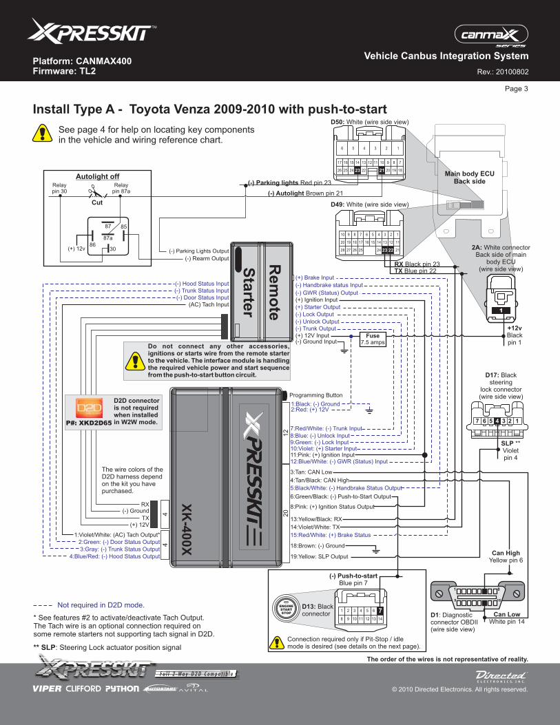
Install Type A - Toyota Venza 2009-2010 with push-to-start
Page 3
Main body ECUBack side
D50: White (wire side view)
D49: White (wire side view)
13151618
2326
1417
2425
5678910 4 3 2 1
1220 19 11
2228 27 212223
23 2226 18
10 7
25
13141617
19
8
20
9111215
24
123456
23 21
D17: Blacksteering
lock connector(wire side view)
2A: White connectorBack side of main
body ECU(wire side view)
1235 47 6
Fuse7.5 amps
XK
-400X
Do not connect any other accessories,ignitions or starts wire from the remote starterto the vehicle. The interface module is handlingthe required vehicle power and start sequencefrom the push-to-start button circuit.
18:Brown: (-) Ground
(+) 12v
Relaypin 30
Relaypin 87a
3086
8587
87a
(-) Autolight Brown pin 21
Autolight off
Cut
Connection required only if Pit-Stop / idlemode is desired (see details on the next page).
1:Violet/White: (AC) Tach Output*
2:Green: (-) Door Status Output
3:Gray: (-) Trunk Status Output
4:Blue/Red: (-) Hood Status Output
The order of the wires is not representative of reality.
1
P#: XKD2D65
D2D connectoris not requiredwhen installedin W2W mode.
See page 4 for help on locating key componentsin the vehicle and wiring reference chart.
* See features #2 to activate/deactivate Tach Output.The Tach wire is an optional connection required onsome remote starters not supporting tach signal in D2D.
Not required in D2D mode.
** SLP: Steering Lock actuator position signal
Rev.: 20100802
Platform: CANMAX400Firmware: TL2
© 2010 Directed Electronics. All rights reserved.
Vehicle Canbus Integration System
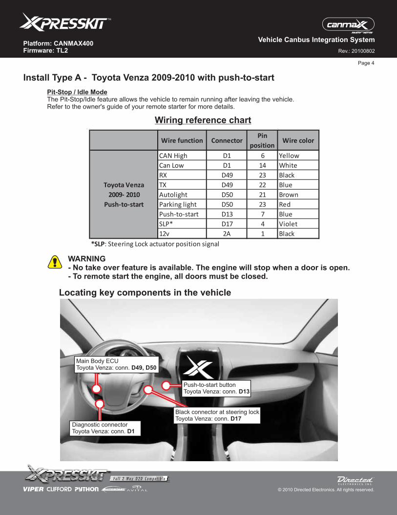
Locating key components in the vehicle
Wiring reference chart
Install Type A - Toyota Venza 2009-2010 with push-to-start
WARNING- No take over feature is available. The engine will stop when a door is open.- To remote start the engine, all doors must be closed.
Page 4
Pit-Stop / Idle ModeThe Pit-Stop/Idle feature allows the vehicle to remain running after leaving the vehicle.Refer to the owner's guide of your remote starter for more details.
Black connector at steering lockToyota Venza: conn. D17
Push-to-start buttonToyota Venza: conn. D13
Main Body ECUToyota Venza: conn. D49, D50
Diagnostic connectorToyota Venza: conn. D1
Wire function ConnectorPin
positionWire color
CAN High D1 6 Yellow
Can Low D1 14 White
RX D49 23 Black
TX D49 22 Blue
Autolight D50 21 Brown
Parking light D50 23 Red
Push-to-start D13 7 Blue
SLP* D17 4 Violet
12v 2A 1 Black
*SLP: Steering Lock actuator position signal
Toyota Venza
2009- 2010
Push-to-start
Rev.: 20100802
Platform: CANMAX400Firmware: TL2
© 2010 Directed Electronics. All rights reserved.
Vehicle Canbus Integration System
(+) 12V
RX(-) Ground
TX
Page 5
12
4 20
15:Red/White: (+) Brake Status
3:Tan: CAN Low
(-) Unlock Output
(-) AUX1
(-) Lock Output
(+) Starter Output
11:Pink: (+) Ignition Input
1:Black: (-) Ground - - - - Ground(-)
(-) Ground Input
2:Red: (+) 12V(+) 12V - - - - - - -
(+) 12V Input
8:Blue: (-) Unlock Input
6:Blue: (-) Sliding door driver**
5:Black/White: (-) Handbrake Status Output
9:Green: (-) Lock Input10:Violet: (+) Starter Input
12:Blue/White: (-) GWR (Status) Input
(-) GWR (Status) Output
8:Pink: (+) Ignition Status Output
Diagnosticconnector OBDII
Whiteconnector(wire side view)
13:Yellow/Black: RX
The wire colors of theD2D harness dependon the kit you havepurchased.
(AC) Tach Input
(-) Trunk Status Input
(-) Hood Status Input
(-) Door Status Input
14:Violet/White: TX
19:Yellow: SLP Output
18:Brown: (-) Ground
4:Tan/Black: CAN High
6:Green/Black: (-) Push-to-Start Output
Programming Button
Rem
ote
Sta
rter
4
(+) Ignition Input
RX pin 4
(-) Parking lights pin 30
TX pin 16
(+) Brake Input
(-) Handbrake status Input
(-) Parking Lights Output
1 8
169
Can Lowpin 14
(-) Push-to-startpin 7
1 3 4 5 7
12 1411108
2
9
6
13
ENGINESTARTSTOP
Can Highpin 6
7Black
connector
Fuse7.5 amps
1 72
5
83
6
9 21
22
25
10
13
23
26
11
14
17 29
24
27
12
15
18
20
19
30
4 16
SLP **pin 4
Black steeringlock connector(wire side view)
1235 47 6
XK
-400X
MainBodyECU
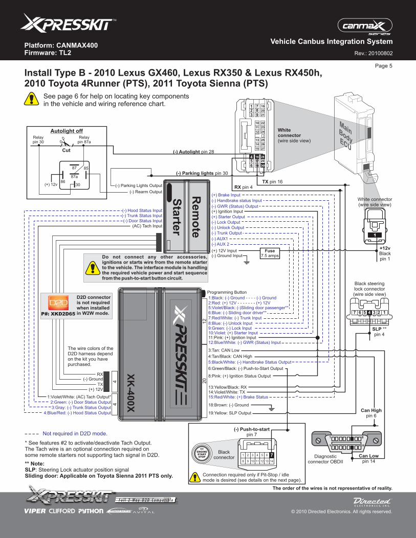
Do not connect any other accessories,ignitions or starts wire from the remote starterto the vehicle. The interface module is handlingthe required vehicle power and start sequencefrom the push-to-start button circuit.
(-) Trunk Output
(-) AUX 2
7:Red/White: (-) Trunk Input
5:Violet/Black: (-)Sliding door passenger**
(-) Rearm Output
(+) 12v
Relaypin 30
3086
8587
87a
Autolight off
Cut
28
(-) Autolight pin 28
Relaypin 87a
Connection required only if Pit-Stop / idlemode is desired (see details on the next page).
1:Violet/White: (AC) Tach Output*
2:Green: (-) Door Status Output
3:Gray: (-) Trunk Status Output
4:Blue/Red: (-) Hood Status Output
The order of the wires is not representative of reality.
+12vBlackpin 1
White connector(wire side view)
1
P#: XKD2D65
D2D connectoris not requiredwhen installedin W2W mode.
See page 6 for help on locating key componentsin the vehicle and wiring reference chart.
* See features #2 to activate/deactivate Tach Output.The Tach wire is an optional connection required onsome remote starters not supporting tach signal in D2D.
Not required in D2D mode.
** Note:SLPSliding door: Applicable on Toyota Sienna 2011 PTS only.
: Steering Lock actuator position signal
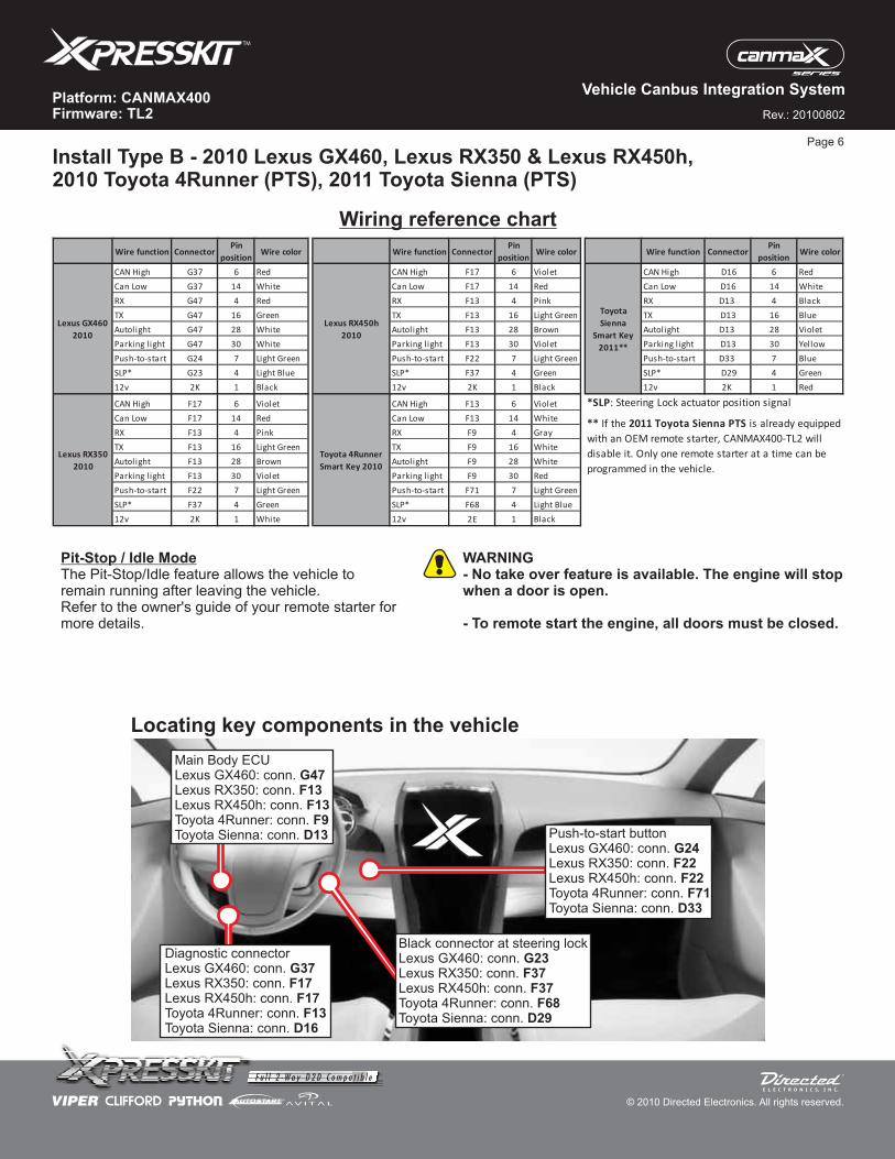
Install Type B - 2010 Lexus GX460, Lexus RX350 & Lexus RX450h,2010 Toyota 4Runner (PTS), 2011 Toyota Sienna (PTS)
Rev.: 20100802
Platform: CANMAX400Firmware: TL2
© 2010 Directed Electronics. All rights reserved.
Vehicle Canbus Integration System
Install Type B - 2010 Lexus GX460, Lexus RX350 & Lexus RX450h,2010 Toyota 4Runner (PTS), 2011 Toyota Sienna (PTS)
Wiring reference chart
WARNING- No take over feature is available. The engine will stopwhen a door is open.
- To remote start the engine, all doors must be closed.
Page 6
Pit-Stop / Idle ModeThe Pit-Stop/Idle feature allows the vehicle toremain running after leaving the vehicle.Refer to the owner's guide of your remote starter formore details.
Locating key components in the vehicle
Diagnostic connectorLexus GX460: conn.Lexus RX350: conn.Lexus RX450h: conn.Toyota 4Runner: conn.Toyota Sienna: conn.
G37F17
F17F13
D16
Main Body ECU
Lexus RX350: conn.Lexus RX450h: conn.Toyota 4Runner: conn.Toyota Sienna: conn.
Lexus GX460: conn. G47F13
F13F9
D13 Push-to-start buttonLexus GX460: conn.Lexus RX350: conn.Lexus RX450h: conn.Toyota 4Runner: conn.Toyota Sienna: conn.
G24F22
F22F71
D33
Black connector at steering lockLexus GX460: conn.Lexus RX350: conn.Lexus RX450h: conn.Toyota 4Runner: conn.Toyota Sienna: conn.
G23F37
F37F68
D29
Wire function ConnectorPin
positionWire color Wire function Connector
Pin
positionWire color Wire function Connector
Pin
positionWire color
CAN High G37 6 Red CAN High F17 6 Violet CAN High D16 6 Red
Can Low G37 14 White Can Low F17 14 Red Can Low D16 14 White
RX G47 4 Red RX F13 4 Pink RX D13 4 Black
TX G47 16 Green TX F13 16 Light Green TX D13 16 Blue
Autolight G47 28 White Autolight F13 28 Brown Autolight D13 28 Violet
Parking light G47 30 White Parking light F13 30 Violet Parking light D13 30 Yellow
Push-to-start G24 7 Light Green Push-to-start F22 7 Light Green Push-to-start D33 7 Blue
SLP* G23 4 Light Blue SLP* F37 4 Green SLP* D29 4 Green
12v 2K 1 Black 12v 2K 1 Black 12v 2K 1 Red
CAN High F17 6 Violet CAN High F13 6 Violet
Can Low F17 14 Red Can Low F13 14 White
RX F13 4 Pink RX F9 4 Gray
TX F13 16 Light Green TX F9 16 White
Autolight F13 28 Brown Autolight F9 28 White
Parking light F13 30 Violet Parking light F9 30 Red
Push-to-start F22 7 Light Green Push-to-start F71 7 Light Green
SLP* F37 4 Green SLP* F68 4 Light Blue
12v 2K 1 White 12v 2E 1 Black
Lexus RX350
2010
Lexus GX460
2010
Toyota
Sienna
Smart Key
2011**
** If the 2011 Toyota Sienna PTS is already equipped
with an OEM remote starter, CANMAX400-TL2 will
disable it. Only one remote starter at a time can be
programmed in the vehicle.
Lexus RX450h
2010
Toyota 4Runner
Smart Key 2010
*SLP: Steering Lock actuator position signal
Rev.: 20100802
Platform: CANMAX400Firmware: TL2
© 2010 Directed Electronics. All rights reserved.
Vehicle Canbus Integration System
(+) 12V
RX(-) Ground
TX
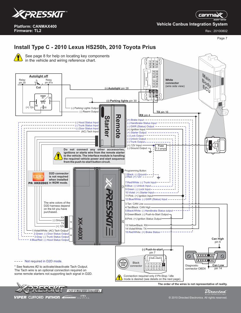
Install Type C - 2010 Lexus HS250h, 2010 Toyota Prius
Page 7
12
4 20
15:Red/White: (+) Brake Status
3:Tan: CAN Low
(-) Unlock Output
(-) Lock Output
(+) Starter Output
11:Pink: (+) Ignition Input
1:Black: (-) Ground
(-) Ground Output
2:Red: (+) 12V
(+) 12V Input
8:Blue: (-) Unlock Input
5:Black/White: (-) Handbrake Status output
9:Green: (-) Lock Input
10:Violet: (+) Starter Input
12:Blue/White: (-) GWR (Status) Input
(-) GWR (Status) Output
8:Pink: (+) Ignition Status Output
Diagnosticconnector OBDII
13:Yellow/Black: RX
The wire colors of theD2D harness dependon the kit you havepurchased.
(AC) Tach Input
(-) Trunk Status Input
(-) Hood Status Input
(-) Door Status Input
14:Violet/White: TX
4:Tan/Black: CAN High
6:Green/Black: (-) Push-to-Start Output
Programming Button
Rem
ote
Sta
rter
4
(+) Ignition Input
(+) Brake Input
(-) Handbrake Status Input
(-) Parking Lights Output
1 8
169
Can Lowpin 14
(-) Push-to-startpin 7
1 3 4 5 7
12 1411108
2
9
6
13
ENGINESTARTSTOP
Can Highpin 6
7Black
connector
Whiteconnector(wire side view)
RX pin 4
(-) Parking lights pin 30
TX pin 16
1 72
5
83
6
9 21
22
25
10
13
28
23
26
11
14
17 29
24
27
12
15
18
20
19
30
4 16
MainBodyECU
1
XK
-400X
Do not connect any other accessories,ignitions or starts wire from the remote starterto the vehicle. The interface module is handlingthe required vehicle power and start sequencefrom the push-to-start button circuit.
Fuse7.5 amps
(-) Trunk Output
7:Red/White: (-) Trunk Input
(-) Rearm Output
(+) 12v
Relaypin 30
3086
8587
87a
Autolight off
Cut
28
(-) Autolight pin 28
Relaypin 87a
Connection required only if Pit-Stop / idlemode is desired (see details on the next page).
1:Violet/White: (AC) Tach Output*
2:Green: (-) Door Status Output
3:Gray: (-) Trunk Status Output
4:Blue/Red: (-) Hood Status Output
The order of the wires is not representative of reality.
P#: XKD2D65
D2D connectoris not requiredwhen installedin W2W mode.
See page 8 for help on locating key componentsin the vehicle and wiring reference chart.
* See features #2 to activate/deactivate Tach Output.The Tach wire is an optional connection required onsome remote starters not supporting tach signal in D2D.
Not required in D2D mode.
Rev.: 20100802
Platform: CANMAX400Firmware: TL2
© 2010 Directed Electronics. All rights reserved.
Vehicle Canbus Integration System
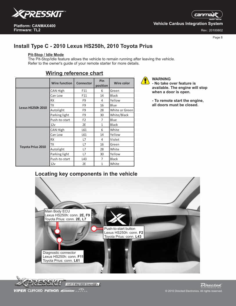
Install Type C - 2010 Lexus HS250h, 2010 Toyota Prius
Wiring reference chart
Locating key components in the vehicle
Page 8
WARNING- No take over feature isavailable. The engine will stopwhen a door is open.
- To remote start the engine,all doors must be closed.
Pit-Stop / Idle ModeThe Pit-Stop/Idle feature allows the vehicle to remain running after leaving the vehicle.Refer to the owner's guide of your remote starter for more details.
Wire function ConnectorPin
positionWire color
CAN High F11 6 Green
Can Low F11 14 Black
RX F9 4 Yellow
TX F9 16 Blue
Autolight F9 28 White or Green
Parking light F9 30 White/Black
Push-to-start F2 7 Blue
12v 2E 1 Black
CAN High L61 6 White
Can Low L61 14 Yellow
RX L7 4 Violet
TX L7 16 Green
Autolight L7 28 White
Parking light L7 30 Yellow
Push-to-start L43 7 Black
12v 2E 1 White
Lexus HS250h 2010
Toyota Prius 2010
Diagnostic connectorLexus HS250h: conn.Toyota Prius: conn.
F11L61
Main Body ECULexus HS250h: conn.Toyota Prius: conn.
2E, F92E, L7
Push-to-start buttonLexus HS250h: conn.Toyota Prius: conn.
F2L43
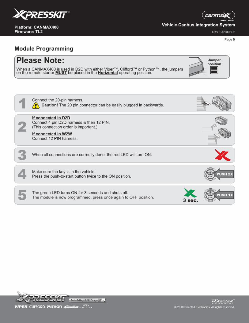
Please Note:When a CANMAX400 is used in D2D with either Viper , Clifford or Python , the jumperson the remote starter be placed in the operating position.
™ ™ ™
MUST Horizontal
Jumperposition
Rev.: 20100802
Platform: CANMAX400Firmware: TL2
© 2010 Directed Electronics. All rights reserved.
Vehicle Canbus Integration System
Module Programming
Page 9
1
When all connections are correctly done, the red LED will turn ON.
2
3
4
5 The green LED turns ON for 3 seconds and shuts off.The module is now programmed, press once again to OFF position.
3 sec.
ENGINESTARTSTOP
PUSH 2X
ENGINESTARTSTOP
PUSH 1X
Make sure the key is in the vehicle.Press the push-to-start button twice to the ON position.
If connected in W2WConnect 12 PIN harness.
If connected in D2DConnect 4 pin D2D harness & then 12 PIN.(This connection order is important.)
Caution! The 20 pin connector can be easily plugged in backwards.
Connect the 20-pin harness.

Rev.: 20100802
Platform: CANMAX400Firmware: TL2
© 2010 Directed Electronics. All rights reserved.
Vehicle Canbus Integration System
& OR
To enter feature programming routine
Accessing another feature
Once a feature is programmed
Press the Push-to-Start (PTS) button twice to turn the ignition ON, then press the button once to turn it OFF.Within 5 sec, press and HOLD the integrated programming button (IPB). The orange LED turns ON after 3 seconds. Release theIPB.The green LED starts flashing slowly one time to indicate the feature number is 1. After a short delay, the red LED flashes rapidlyone time to indicate the current option of feature 1. It repeats until next action happens.
Press and release the IPB a number of times to advance from the current feature to the next desired .The green LED flashes slowly the number of times equal to the feature number. After a short delay, the red LED flashes rapidly onetime to indicate the current option of the current feature. It repeats until next action happens.
Another feature(s) can be programmed.The feature programming can be exited.
When the maximum number of feature or option is reached, the will LED starts flashing again from the first feature or option.
-
-
-
-
-
-
-
Changing feature options-
-Press the lock/arm or unlock/disarm button on aftermarket transmitter to change the option of the selected feature.The red LED flashes rapidly the number of times equal to the current option number. After a short delay, the green LED flashesslowly the number of times to indicate the current feature. It repeats until next action happens.
feature
Exiting feature programming-
-
No activity for 30 seconds; after 30 seconds, the orange LED will turn ON for 2 seconds to confirm exiting.ORPress and HOLD the IPB for 3 seconds. After 3 seconds, the orange LED will turn ON for 2 seconds to confirm exiting.
IntegratedProgrammingButton (IPB)
Page 10
Feature Programming
*Default Option
Features Operation Option
No RF Output*
RFTD Output
Disabled
Enabled*
RF output type
Activate this feature whenever an external
RFTD module is used (i.e.: XL201 or XL202)
1
2 Tach Output (W2W only)
1
2
3
Press and hold the Programming button, then powerup the module:- D2D: connect the D2D cable; or,- W2W: connect the 12-pin harness.
When the LED turns ON orange, release the Programming button.Once the LED turns ON red, the module reset is complete. & &
Connect the 20-pin harness.
Feature and Option List
Resetting the Module
Solid Orange Solid Red
Rev.: 20100802
Platform: CANMAX400Firmware: TL2
© 2010 Directed Electronics. All rights reserved.
Vehicle Canbus Integration System
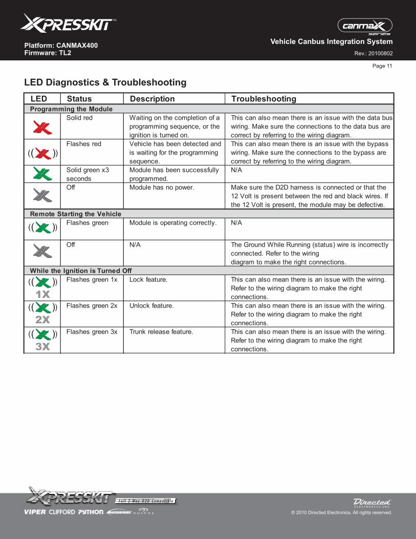
LED Status Description Troubleshooting
Programming the Module
Solid red Waiting on the completion of a
programming sequence, or the
ignition is turned on.
This can also mean there is an issue with the data bus
wiring. Make sure the connections to the data bus are
correct by referring to the wiring diagram.
Flashes red Vehicle has been detected and
is waiting for the programming
sequence.
This can also mean there is an issue with the bypass
wiring. Make sure the connections to the bypass are
correct by referring to the wiring diagram.
Solid green x3
seconds
Module has been successfully
programmed.
N/A
Off Module has no power. Make sure the D2D harness is connected or that the
12 Volt is present between the red and black wires. If
the 12 Volt is present, the module may be defective.
Remote Starting the Vehicle
Flashes green Module is operating correctly. N/A
Off N/A The Ground While Running (status) wire is incorrectly
connected. Refer to the wiring
diagram to make the right connections.
While the Ignition is Turned Off
Flashes green 1x Lock feature. This can also mean there is an issue with the wiring.
Refer to the wiring diagram to make the right
connections.
Flashes green 2x Unlock feature. This can also mean there is an issue with the wiring.
Refer to the wiring diagram to make the right
connections.
Flashes green 3x Trunk release feature. This can also mean there is an issue with the wiring.
Refer to the wiring diagram to make the right
connections.
( )( )
( )( )
( )( )
( )( )
( )( )
3X
2X
1X
Page 11
LED Diagnostics & Troubleshooting
For a period of ONE YEAR from the date of purchase of a Directed Electronics remote start or security product, DirectedElectronics. (“DIRECTED”) promises to the original purchaser, to repair or replace with a comparable reconditioned piece, thesecurity or remote start accessory piece (hereinafter the “Part”), which proves to be defective in workmanship or materialunder normal use, provided the following conditions are met: the Part was purchased from an authorized DIRECTED dealer;and the Part is returned to DIRECTED, postage prepaid, along with a clear, legible copy of the receipt or bill of sale bearing thefollowing information: consumer’s name, address, telephone number, the authorized licensed dealer’s name and completeproduct and Part description.
This warranty is nontransferable and is automatically void if the Part has been modified or used in a manner contrary to itsintended purpose or the Part has been damaged by accident, unreasonable use, neglect, improper service, installation orother causes not arising out of defect in materials or construction.
TO THE MAXIMUM EXTENT ALLOWED BY LAW, ALL WARRANTIES, INCLUDING BUT NOT LIMITED TO EXPRESSWARRANTY, IMPLIED WARRANTY, WARRANTY OF MERCHANTABILITY, FITNESS FOR PARTICULAR PURPOSE ANDWARRANTY OF NON INFRINGEMENT OF INTELLECTUAL PROPERTY,ARE EXPRESSLY EXCLUDED;AND DIRECTEDNEITHER ASSUMES NOR AUTHORIZES ANY PERSON OR ENTITY TO ASSUME FOR IT ANY DUTY, OBLIGATION ORLIABILITY IN CONNECTION WITH ITS PRODUCTS. DIRECTED HEREBY DISCLAIMS AND HAS ABSOLUTELY NOLIABILITY FOR ANY AND ALL ACTS OF THIRD PARTIES INCLUDING DEALERS OR INSTALLERS. IN THE EVENT OF ACLAIM OR A DISPUTE INVOLVING DIRECTED OR ITS SUBSIDIARY, THE PROPER VENUE SHALL BE SAN DIEGOCOUNTY IN THE STATE OF CALIFORNIA. CALIFORNIASTATE LAWSANDAPPLICABLE FEDERAL LAWS SHALLAPPLYAND GOVERN THE DISPUTE. THE MAXIMUM RECOVERY UNDER ANY CLAIM AGAINST DIRECTED SHALL BESTRICTLY LIMITED TO THE AUTHORIZED DIRECTED DEALER’S PURCHASE PRICE OF THE PART. DIRECTED SHALLNOT BE RESPONSIBLE FOR ANY DAMAGES WHATSOEVER, INCLUDING BUT NOT LIMITED TO, ANYCONSEQUENTIAL DAMAGES, INCIDENTAL DAMAGES, DAMAGES FOR THE LOSS OF TIME, LOSS OF EARNINGS,COMMERCIAL LOSS, LOSS OF ECONOMIC OPPORTUNITY AND THE LIKE. NOTWITHSTANDING THE ABOVE, THEMANUFACTURER DOES OFFERALIMITED WARRANTY TO REPLACE OR REPAIRAT DIRECTED’S OPTION THE PARTAS DESCRIBEDABOVE.
Some states do not allow limitations on how long an implied warranty will last or the exclusion or limitation of incidental orconsequential damages. This warranty gives you specific legal rights and you may also have other rights that vary fromState to State. DIRECTED does not and has not authorized any person or entity to create for it any other obligation,promise, duty or obligation in connection with this Part.920-0007 07-06
This Interface kit / Data Bus Interface part has been tested on the listed vehicles. Other vehicles will be added to the select
vehicle list upon completion of compatibility testing. Visit website for latest vehicle application guide. : Under no
circumstances shall the manufacturer or the distributors of the bypass kit / data bus interface part(s) be held liable for any
consequential damages sustained in connection with the part(s) installation. The manufacturer and it’s distributors will not, nor
will they authorize any representative or any other individual to assume obligation or liability in relation to the interface kit / data
bus interface part(s) other than its replacement.
DISCLAIMER
N.B.:Under no circumstances shall the manufacturer and distributors of this
product be liable for consequential damages sustained in connection with this product and neither assumes nor authorizes
any representative or other person to assume for it any obligation or liability other than the replacement of this product only.
PROTECTED BY U.S. PATENTS:
CDN. PATENT:EUROPEAN PATENT: PAT. PENDING: MADE IN CANADA2,291,306;
5,719,551; 6,011,460 B1 *;6,243,004 B1; 6,249,216 B1; 6,275,147 B1; 6,297,731 B1; 6,346,876 B1; 6,392,534 B1; 6,529,124B2; 6,696,927 B2; 6,756,885 B1; 6,756,886 B2; 6,771,167 B1; 6,812,829 B1; 6,924,750 B1; 7,010,402 B1; 7,015,830 B1; 7,031,826 B1; 7 ,046 ,126 B1 ;7,061,137 B1; 7,068,153 B1; 7,205,679 B1; 2,320,248; 2,414,991; 2,415,011; 2,415,023; 2,415,027; 2,415,038; 2,415,041; 2 , 4 2 0 , 9 4 7 ;2,426,670; 2,454,089 1,053,128
Rev.: 20100802
Platform: CANMAX400Firmware: TL2
© 2010 Directed Electronics. All rights reserved.
Vehicle Canbus Integration System
Limited One-Year Consumer Warranty
Page 12