installation guide - alte inverter/charger unit installed, the ac switchgear can be positioned...
TRANSCRIPT
975-0676-01-01 REV BCopyright © 2012 Schneider Electric. All Rights Reserved. All trademarks are owned by Schneider Electric Industries SAS or its affiliated companies.
For use by qualified installers only.Page 1 of 2
ConextTM SW AC Switchgear 120/240V (865-1017)Installation Guide
Important Safety InstructionsREAD AND SAVE THESE INSTRUCTIONS - DO NOT DISCARD
Installation
Materials List
1. Choose a location to mount the AC switchgear. If you already have a Conext SW inverter/charger unit installed, the AC switchgear can be positioned directly underneath (see an illustration on the back page) or on top of the inverter/charger.
2. Remove the AC switchgear cover to expose the mounting key holes.3. Mount the AC switchgear. Use the mounting template on the back page to mark
the mounting holes on the mounting surface.4. Make the proper wiring connections. Use only qualified personnel to ensure
compliance with all applicable installation and electrical codes and regulations.5. Replace the AC switchgear cover. Secure the cover using the same screws that
came with the product.
The Conext SW AC Switchgear (865-1017) ships with the following items:
ELECTRIC SHOCK, EXPLOSION, AND ARC FLASH HAZARDS
Failure to follow these instructions will result in death or serious injury.
All wiring must be done by qualified personnel to ensure compliance with all applicable installation codes and regulations.Disconnect and lockout all DC and AC sources that are powering this equipment and any connected equipment before installing, servic-ing, and performing any upgrades.Always wear proper personal protective equipment (PPE) before working on or inside this equipment.Always use a properly rated voltage sensing device to check the presence of potential and residual energy.Do not route and mix DC cables and wires with AC cables and wires within the same compart-ment. This equipment is equipped with a partition (item O) that isolates AC wiring from DC wiring.
DANGER!EQUIPMENT DAMAGE
Failure to follow these instructions can cause equipment damage.
Do not remove the pre-installed Handle Interlock device (item C).
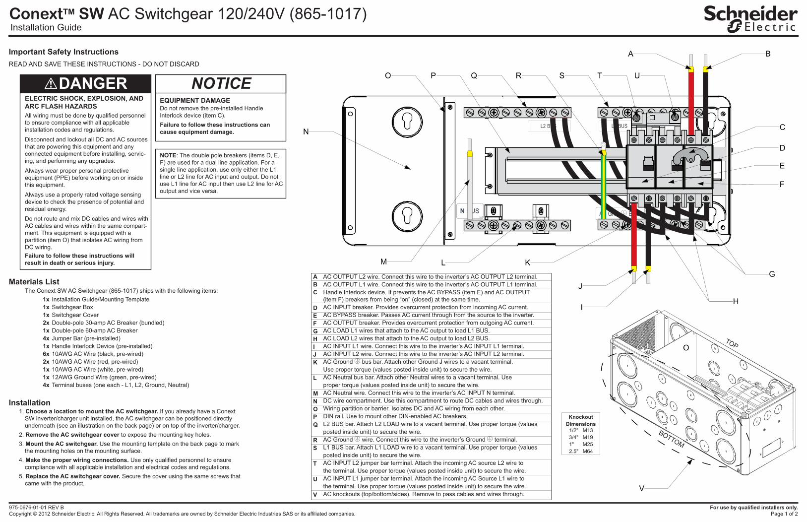
NOTE: The double pole breakers (items D, E, F) are used for a dual line application. For a single line application, use only either the L1 line or L2 line for AC input and output. Do not use L1 line for AC input then use L2 line for AC output and vice versa.
NOTICE
BA
Q R
J
I
T U
C
O
L K
D
E
F
N
P
ABC
DEFGHIJK
L
MNOPQ
RS
T
U
V
AC OUTPUT L2 wire. Connect this wire to the inverter’s AC OUTPUT L2 terminal.AC OUTPUT L1 wire. Connect this wire to the inverter’s AC OUTPUT L1 terminal.Handle Interlock device. It prevents the AC BYPASS (item E) and AC OUTPUT(item F) breakers from being “on” (closed) at the same time.AC INPUT breaker. Provides overcurrent protection from incoming AC current.AC BYPASS breaker. Passes AC current through from the source to the inverter.AC OUTPUT breaker. Provides overcurrent protection from outgoing AC current.AC LOAD L1 wires that attach to the AC output to load L1 BUS.AC LOAD L2 wires that attach to the AC output to load L2 BUS.AC INPUT L1 wire. Connect this wire to the inverter’s AC INPUT L1 terminal.AC INPUT L2 wire. Connect this wire to the inverter’s AC INPUT L2 terminal.AC Ground bus bar. Attach other Ground J wires to a vacant terminal.Use proper torque (values posted inside unit) to secure the wire.AC Neutral bus bar. Attach other Neutral wires to a vacant terminal. Use proper torque (values posted inside unit) to secure the wire.AC Neutral wire. Connect this wire to the inverter’s AC INPUT N terminal.DC wire compartment. Use this compartment to route DC cables and wires through.Wiring partition or barrier. Isolates DC and AC wiring from each other.DIN rail. Use to mount other DIN-enabled AC breakers.L2 BUS bar. Attach L2 LOAD wire to a vacant terminal. Use proper torque (values posted inside unit) to secure the wire.AC Ground wire. Connect this wire to the inverter’s Ground terminal.L1 BUS bar. Attach L1 LOAD wire to a vacant terminal. Use proper torque (values posted inside unit) to secure the wire.AC INPUT L2 jumper bar terminal. Attach the incoming AC source L2 wire to the terminal. Use proper torque (values posted inside unit) to secure the wire.AC INPUT L1 jumper bar terminal. Attach the incoming AC Source L1 wire to the terminal. Use proper torque (values posted inside unit) to secure the wire.AC knockouts (top/bottom/sides). Remove to pass cables and wires through.
1x1x1x2x1x4x1x6x2x1x1x4x
Installation Guide/Mounting TemplateSwitchgear BoxSwitchgear CoverDouble-pole 30-amp AC Breaker (bundled)Double-pole 60-amp AC BreakerJumper Bar (pre-installed)Handle Interlock Device (pre-installed)10AWG AC Wire (black, pre-wired)10AWG AC Wire (red, pre-wired)10AWG AC Wire (white, pre-wired)12AWG Ground Wire (green, pre-wired)Terminal buses (one each - L1, L2, Ground, Neutral)
G
H
M
S
V
OTOP
BOTTOM
KnockoutDimensions
1/2"3/4"1"2.5"
M13M19M25M64
C
M
Y
CM
MY
CY
CMY
K
975-0676-01-01_Rev-B(artwork).pdf 1 1/18/2013 11:51:06 AM
975-0676-01-01 REV B Printed in ChinaCopyright © 2012 Schneider Electric. All Rights Reserved. All trademarks are owned by Schneider Electric Industries SAS or its affiliated companies.
For use by qualified installers only.Page 2 of 2
Conext SW AC Switchgear 120/240V (865-1017)Mounting Template
Contact Informationwww.schneider-electric.comPlease contact your local Schneider Electric Sales Representative or visit the Schneider Electric website at:http://www.schneider-electric.com/sites/corporate/en/support/operations/local-operations/local-operations.page
Exclusion for DocumentationUNLESS SPECIFICALLY AGREED TO IN WRITING, SELLER
(A) MAKES NO WARRANTY AS TO THE ACCURACY, SUFFICIENCY OR SUITABILITY OF ANY TECHNICAL OR OTHER INFORMATION PROVIDED IN ITS MANUALS OR OTHER DOCUMENTATION;(B) ASSUMES NO RESPONSIBILITY OR LIABILITY FOR LOSSES, DAMAGES, COSTS OR EXPENSES, WHETHER SPECIAL, DIRECT, INDIRECT, CONSEQUENTIAL OR INCIDENTAL, WHICH MIGHT ARISE OUT OF THE USE OF SUCH INFORMATION. THE USE OF ANY SUCH INFORMATION WILL BE ENTIRELY AT THE USER’S RISK; AND
(C) REMINDS YOU THAT IF THIS MANUAL IS IN ANY LANGUAGE OTHER THAN ENGLISH, ALTHOUGH STEPS HAVE BEEN TAKEN TO MAINTAIN THE ACCURACY OF THE TRANSLATION, THE ACCURACY CANNOT BE GUARANTEED. APPROVED CONTENT IS CONTAINED WITH THE ENGLISH LANGUAGE VERSION WHICH IS POSTED AT WWW.SCHNEIDER-ELECTRIC.COM.
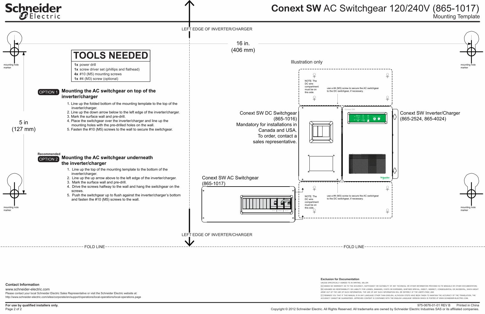
16 in.(406 mm)
5 in(127 mm)
Conext SW Inverter/Charger(865-2524, 865-4024)
Conext SW DC Switchgear(865-1016)
Mandatory for installations inCanada and USA.To order, contact a
sales representative.
Conext SW AC Switchgear(865-1017)
Mounting the AC switchgear on top of theinverter/charger
Mounting the AC switchgear underneaththe inverter/charger
1. Line up the top of the mounting template to the bottom of the inverter/charger.
2. Line up the up arrow above to the left edge of the inverter/charger.3. Mark the surface wall and pre-drill.4. Drive the screws halfway to the wall and hang the switchgear on the
screws.5. Push the switchgear up to flush against the inverter/charger’s bottom
and fasten the #10 (M5) screws to the wall.
1. Line up the folded bottom of the mounting template to the top of the inverter/charger.
2. Line up the down arrow below to the left edge of the inverter/charger.3. Mark the surface wall and pre-drill.4. Place the switchgear over the inverter/charger and line up the
mounting holes with the pre-drilled holes on the wall.5. Fasten the #10 (M5) screws to the wall to secure the switchgear.
FOLD LINE
LEFT EDGE OF INVERTER/CHARGER
LEFT EDGE OF INVERTER/CHARGER
FOLD LINE
TOOLS NEEDED1x1x4x1x
power drillscrew driver set (phillips and flathead)#10 (M5) mounting screws#4 (M3) screw (optional)
mounting holemarker
mounting holemarker
mounting holemarker
mounting holemarker
use a #4 (M3) screw to secure the AC switchgearto the DC switchgear, if necessary.
NOTE: The DC wirecompartmentmust be on this side.
NOTE: The DC wirecompartmentmust be on this side.
use a #4 (M3) screw to secure the AC switchgearto the DC switchgear, if necessary.
Illustration only
OPTION 1
OPTION 2Recommended
C
M
Y
CM
MY
CY
CMY
K
975-0676-01-01_Rev-B(artwork).pdf 2 1/18/2013 11:51:07 AM