installation guide 862 mit / mir - honeywell · safety installation guide 862 mit / mir page 3...
TRANSCRIPT

Installation guide 862 MIT / MIR Page 1
Installation guide 862 MIT / MIR
in combination with: 864 MTT or863 MRT or (dual) spot element
November 2005Part no. 4416.232_Rev3
Enraf BVPO Box 8122600 AV DelftNetherlands
Tel. : +31 15 2701 100Fax : +31 15 2701 111E-mail : [email protected] : http://www.enraf.com
Preface
Page 2
Preface
This installation guide is intended for technicians involved in the mechanical and electricalinstallation of the Enraf Series 862.
• Multi element Interface Thermo sensor converter (862 MIT)• Multi element Interface Resistance thermometer (862 MIR)
This guide describes the installation of the two different models of the 862.
The technician must have basic technical skills and knowledge of safety regulations and explosionproof equipment in hazardous areas.
EC declaration of conformity
Refer to the EC declaration of conformity, shipped with the instrument.
Note:The connection to the instrument must be made with shielded cable. The shielding must begrounded in the cable gland on both ends of the cable.
Legal aspects
The mechanical and electrical installation shall only be carried out by trained personnel withknowledge of the requirements for installation of explosion proof equipment in hazardous areas.
The information in this installation guide is the copyright property of Enraf BV, Netherlands.Enraf BV disclaims any responsibility for personal injury or damage to equipment caused by:
• Deviation from any of the prescribed procedures;• Execution of activities that are not prescribed;• Neglect of the general safety precautions for handling tools, use of electricity and
microwave radiation.
The contents, descriptions and specifications are subject to change without notice.Enraf BV accepts no responsibility for any errors that may appear in this installation guide.
Additional information
Please do not hesitate to contact Enraf or its representative if you require additional information.

Safety
Installation guide 862 MIT / MIR Page 3
Safety
Safety aspects of the 862 MIT / MIR
The housing of the 862 MIT / MIR consists of a weather proof aluminium box IP65 acc. toIEC 529.
The signals from the level gauge to the 862 MIT / MIR are:
• II 1/2 G EEx ib IIB T4, KEMA 03ATEX1475 X • Class I, Division 1, Groups C and D acc. to ANSI/NFPA No. 70, certified by Factory Mutual
Research USA
The signals from the 862 MIT / MIR to the temperature element are:
• II 1/2 G EEx ia IIB T4, KEMA 03ATEX1475 X• Class I, Division 1, Groups C and D acc. to ANSI/NFPA No. 70, certified by Factory Mutual
Research USA
The environmental conditions for the 862 MIT / MIR are:
• ambient temperature : -40 to 60 °C (-40 to 140 °F)• relative humidity : 0 - 100%• ingress protection : IP65 (NEMA 4), suitable for outdoor installation
The 862 MIT / MIR is provided with a lightning protection at the output lines to the Enraf levelgauge.
CautionAll wiring to the 862 MIT / MIR is intrinsically safe.
The entire installation procedure, inclusive routing and grounding,shall be in accordance with national, local and company regulations.
WarningImproper installation of cable glands, conduit or stopping plugs will
invalidate the Ex approval of the 862 MIT / MIR.

Safety
Page 4
Personal safety
The technician must have basic technical skills to be able to safely install the equipment.When the 862 MIT / MIR is installed in a hazardous area, the technician must work inaccordance with the (local) requirements for electrical equipment in hazardous areas.
WarningIn hazardous areas it is compulsory to use personal protection and safety gear such as:
hard hat, fire-resistive overall, safety shoes, safety glasses and working gloves.
Avoid possible generation of static electricity.Use non-sparking tools and explosion proof testers.
Make sure no dangerous quantities of combustible gas mixturesare present in the working area.
Never start working before the work permit has been signed by all parties.
Pay attention to the kind of product in the tank. If any danger for health,wear a gas mask and take all necessary precautions.
Safety conventions
“Warnings”, “Cautions” and “Notes” have been used throughout this installation guide to bringspecial matters to the immediate attention of the reader.
• A Warning concerns danger to the safety of the technician or user;• A Caution draws the attention to an action which may damage the equipment;• A Note points out a statement deserving more emphasis than the general text, but not
requiring a “Warning” or a “Caution”.

Mechanical installation
Installation guide 862 MIT / MIR Page 5
Mechanical installation
CautionThe 862 MIT / MIR may be installed in hazardous areas.
Before starting installation, check whether the actual area of installation complieswith the area classification on the applicable approval certificate for your type of 862.
CautionMake sure no dangerous quantities of combustible products are present in the working area.
Note:The entire installation procedure shall be in accordance with national, local and companyregulations.
The 862 MIT / MIR can be mounted on top of the G ½ threaded pipe of the 864 MTT / 863 MRTor on a nearby rail. It is recommended to mount the 862 MIT / MIR directly on top of the864 MTT / 863 MRT extension pipe.
In the following sections is explained how to installed the 862 MIT / MIR:
• on the extension pipe• the wall mounting• and via a bracket on a rail

Mechanical installation
Page 6
Figure 1 862 MIT / MIR installation on extension pipe 864 MTT / 863 MRT
Installing the 862 MIT / MIR on top of 864 MTT / 863 MRT extension pipe
Refer to figure 1.
• Place G ½ nut (4) and lock washer (3)on extension tube (5).
• Remove the cover from the862 MIT / MIR housing by looseningthe four screws (1).
• Feed the 864 MTT / 863 MRT wiring(2) through the G ½ entry.
• Turn the 862 MIT / MIR on theextension tube (5) of the 864 MTT /863 MRT.
• Secure the 862 MIT / MIR by theG ½ nut (4).
• If the 864 MTT / 863 MRT wiring will beconnected in a later stage, close thecover from the 862 MIT / MIR and sealcable inlet.

Mechanical installation
Installation guide 862 MIT / MIR Page 7
Figure 2 Bracket position on horizontal rail and vertical rail
Installing the 862 MIT / MIR against the wall
The 862 MIT / MIR unit can be installed against the wall or on a bracket. Refer to figure 1and appendix A. The 862 MIT / MIR shall be mounted with the cable entries at bottom side.
• Remove the cover from the 862 MIT / MIR housing by loosening the four screws (1).• Fix the 862 MIT / MIR with four screws of max 6 mm (¼") diameter. The screws are sunk
for 20 mm (13/16") in the 862 MIT / MIR.• If the 864 MTT / 863 MRT wiring will be connected in a later stage, close the cover from the
862 MIT / MIR and seal the cable inlets.
Installing the 862 MIT / MIR on a rail
Determine whether the 862 MIT / MIR unit is to be installed on a horizontal rail or on a vertical rail.As the 862 MIT / MIR shall be mounted with the cable entries at bottom side, the mounting platemust be installed as indicated in figure 2.
• Remove the cover from the 862 MIT / MIR housing by loosening the four screws (1).• Fix the mounting plate to the 862 MIT / MIR as indicated in figure 2. Make use of the four
screws M6 x 30 mm, nuts M6 and lock washers M6.• Place mounting plate with 862 MIT / MIR on rail and secure mounting plate with the two
U-bend brackets.
Note:Check with a vertical rail, if the legs of the lower U-bend bracket do not interfere withthe cable inlets of the 862 MIT / MIR. If so, then cut the remaining part.
• If the 864 MTT / 863 MRT wiring will be connected in a later stage, close the cover from the862 MIT / MIR and seal the cable inlets.

Electrical installation
Page 8
Electrical installation
The entire electrical installation shall be in accordance with International Standard IEC 79-14 forelectrical equipment in hazardous areas.
WarningMake sure that all power to associated instrument is switched off before
opening the cover of the 862.
Failure to do so may cause danger to persons or damage the equipment.The cover of the 862 MIT / MIR must be closed before switching on the power.
CautionMake sure that no dangerous quantities of combustible products are present
in the working area.
Grounding
Proper grounding of 862 MIT / MIR to tank is required.Use external ground terminal on 862 housing (refer to figure 1).
CautionSafety depends on proper grounding. Check the resistance of the ground connection
directly after installation. The measured ground resistance shall be below themaximum prescribed by local grounding requirements.
WarningWhen measuring the ground resistance, use a suitable explosion-proof tester.
Note:Grounding shall be performed in accordance with local regulations.

Electrical installation
Installation guide 862 MIT / MIR Page 9
Supply / transmission
The combined supply / transmission for the 862 MIT / MIR comes from one of the option boardsMPU, HPU or OPU. These boards can be installed in various Enraf instruments such as the 854level gauge, the 873 SmartRadar and the 877 FDI field indicator.
The power rating is: 15 Vdc nominal; current varying between 15-25 mA.
The connection between 862 MIT / MIR and supply board is intrinsically safe. Local and companyrequirements must be followed for the routing of the i.s. wiring.
Cable specifications
The cable length between 862 MIT / MIR and associated instrument (with the MPU, HPU or OPUboard) should be kept as short as possible. The cable requirements are:
• twisted pair and shielded• R : 25 Ω / linemax
• C : 470 nFmax
• L : 0.65 mHmax
C and L may vary depending the values mentioned in the i.s. approval. The correct valuesmax max
are indicated on the identification label of the instrument, in the installation guide of the associatedinstrument, or can be found in the approval certificate.
CautionWiring to and from the 862 MIT / MIR shall be protected against EMC influences.
Note:It is required to use metallic cable glands to provide good contact between cable shield and862 MIT / MIR housing. The screen of the cable should be connected inside the cable gland.
Shielding:
Note:Never connect the shielding inside the 862 MIT / MIR housing. Shielding must be connectedexternally to the housings of the 862 MIT / MIR and associated instrument, or in the cablegland. The shielding must be connected to ground at both sides of the cable.
Electrical installation
Page 10
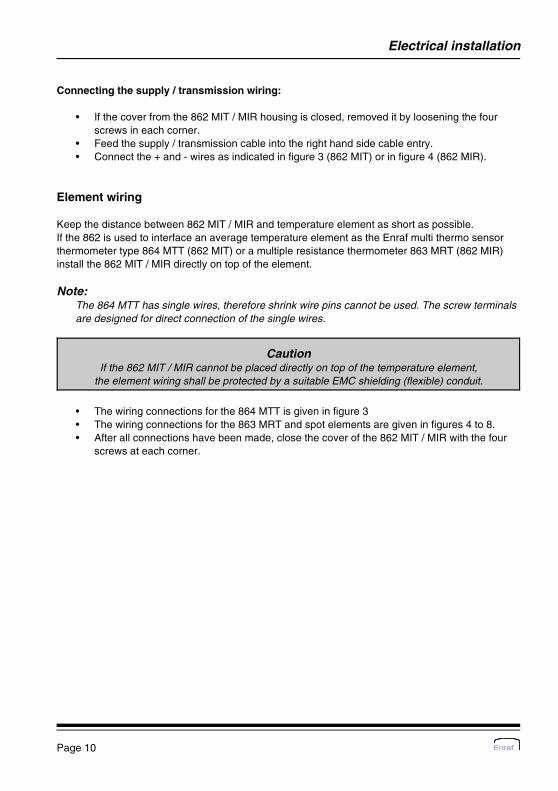
Connecting the supply / transmission wiring:
• If the cover from the 862 MIT / MIR housing is closed, removed it by loosening the fourscrews in each corner.
• Feed the supply / transmission cable into the right hand side cable entry.• Connect the + and - wires as indicated in figure 3 (862 MIT) or in figure 4 (862 MIR).
Element wiring
Keep the distance between 862 MIT / MIR and temperature element as short as possible.If the 862 is used to interface an average temperature element as the Enraf multi thermo sensorthermometer type 864 MTT (862 MIT) or a multiple resistance thermometer 863 MRT (862 MIR)install the 862 MIT / MIR directly on top of the element.
Note:The 864 MTT has single wires, therefore shrink wire pins cannot be used. The screw terminalsare designed for direct connection of the single wires.
CautionIf the 862 MIT / MIR cannot be placed directly on top of the temperature element,
the element wiring shall be protected by a suitable EMC shielding (flexible) conduit.
• The wiring connections for the 864 MTT is given in figure 3• The wiring connections for the 863 MRT and spot elements are given in figures 4 to 8.• After all connections have been made, close the cover of the 862 MIT / MIR with the four
screws at each corner.

Electrical installation
Installation guide 862 MIT / MIR Page 11
Figure 3 862 MIT connection diagram
Connecting the 862 MIT
Note:Before connecting the MTT wiring, ground the 862 MIT housing to the external groundingconnection. When connecting the MTT wiring, first connect the wires on connector CN1,terminals 16 - 18 (one brown wire and two red wires). Insert the female connector CN1 into themale connector on the 862 MIT. Then continue with connecting the other MTT wiring.
Electrical installation
Page 12
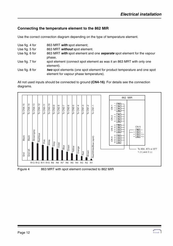
Figure 4 863 MRT with spot element connected to 862 MIR
Connecting the temperature element to the 862 MIR
Use the correct connection diagram depending on the type of temperature element.
Use fig. 4 for 863 MRT with spot element;Use fig. 5 for 863 MRT without spot element.Use fig. 6 for 863 MRT with spot element and one separate spot element for the vapour
phase.Use fig. 7 for spot element (connect spot element as was it an 863 MRT with only one
element).Use fig. 8 for two spot elements (one spot element for product temperature and one spot
element for vapour phase temperature).
All not used inputs should be connected to ground (CN4-16). For details see the connectiondiagrams.

Electrical installation
Installation guide 862 MIT / MIR Page 13
Figure 5 863 MRT without spot element connected to 862 MIR
Figure 6 863 MRT with spot element and one separate vapour phase spot
Electrical installation
Page 14
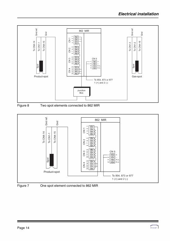
Figure 8 Two spot elements connected to 862 MIR
Figure 7 One spot element connected to 862 MIR

Appendix
Installation guide 862 MIT / MIR Page 15
862 MIT / MIR
Appendix A Dimensional drawings

Appendix
Page 16
862 MIT / MIR with bracket

Appendix
Installation guide 862 MIT / MIR Page 17
Appendix B ATEX approval
The 862 MIR and 862 MIT have been ATEX approved as intrinsically safe.The maximum values according to the ATEX certificate are:
Input circuit EEx ib IIB:862 MIR (terminals CN5/1-4) and 862 MIT (terminals CN6/1-4):
V = 23.3 VoI = 270 mAkP = 1.3 WC = negligibleiL = 1.55 mHi
Measuring circuit EEx ia IIB:862 MIR (terminals CN1-CN4) and 862 MIT (terminals CN1-CN5):
V = 18.4 VoI = 33 mAkP = 75 mWC = 470 nFmaxL = 5 mHmax

Appendix
Page 18
Appendix C Related publications
Installation guide 863 MRTInstallation guide 864 MTT
Installation guide 854 Advanced Technology GaugeInstallation guide 854 XTG Servo Gauge
Installation guide 877 FDIInstallation guide 873 SmartRadar Control Unit
Instruction manual 862 MIR Instruction manual 862 MIT

Notes
Installation guide 862 MIT / MIR Page 19

Page 20