installation and operation manual - rad-russia.pro11_mn.pdf · installation and operation manual...
TRANSCRIPT

Installation and Operation Manual
MEGAPLEX-2100 MODULES
VF-30/VF-60 Single/Dual E1 Digital Voice Compression Modules
Megaplex-2100 Version 11


VF-30/VF-60 Single/Dual E1 Digital Voice Compression Modules
for Megaplex-2100 Version 11 Installation and Operation Manual
Notice This manual contains information that is proprietary to RAD Data Communications Ltd. ("RAD"). No part of this publication may be reproduced in any form whatsoever without prior written approval by RAD Data Communications.
Right, title and interest, all information, copyrights, patents, know-how, trade secrets and other intellectual property or other proprietary rights relating to this manual and to the VF-30/VF-60 and any software components contained therein are proprietary products of RAD protected under international copyright law and shall be and remain solely with RAD.
VF-30/VF-60 is a registered trademark of RAD. No right, license, or interest to such trademark is granted hereunder, and you agree that no such right, license, or interest shall be asserted by you with respect to such trademark.
You shall not copy, reverse compile or reverse assemble all or any portion of the Manual or the VF-30/VF-60. You are prohibited from, and shall not, directly or indirectly, develop, market, distribute, license, or sell any product that supports substantially similar functionality as the VF-30/VF-60, based on or derived in any way from the VF-30/VF-60. Your undertaking in this paragraph shall survive the termination of this Agreement.
This Agreement is effective upon your opening of the VF-30/VF-60 package and shall continue until terminated. RAD may terminate this Agreement upon the breach by you of any term hereof. Upon such termination by RAD, you agree to return to RAD the VF-30/VF-60 and all copies and portions thereof.
For further information contact RAD at the address below or contact your local distributor.
International Headquarters RAD Data Communications Ltd. 24 Raoul Wallenberg St. Tel Aviv 69719 Israel Tel: 972-3-6458181 Fax: 972-3-6498250 E-mail: [email protected]
North America Headquarters RAD Data Communications Inc. 900 Corporate Drive Mahwah, NJ 07430 USA Tel: (201) 529-1100, Toll free: 1-800-444-7234 Fax: (201) 529-5777 E-mail: [email protected]
© 1988–2006 RAD Data Communications Ltd. Publication No. 764-246-08/06

1
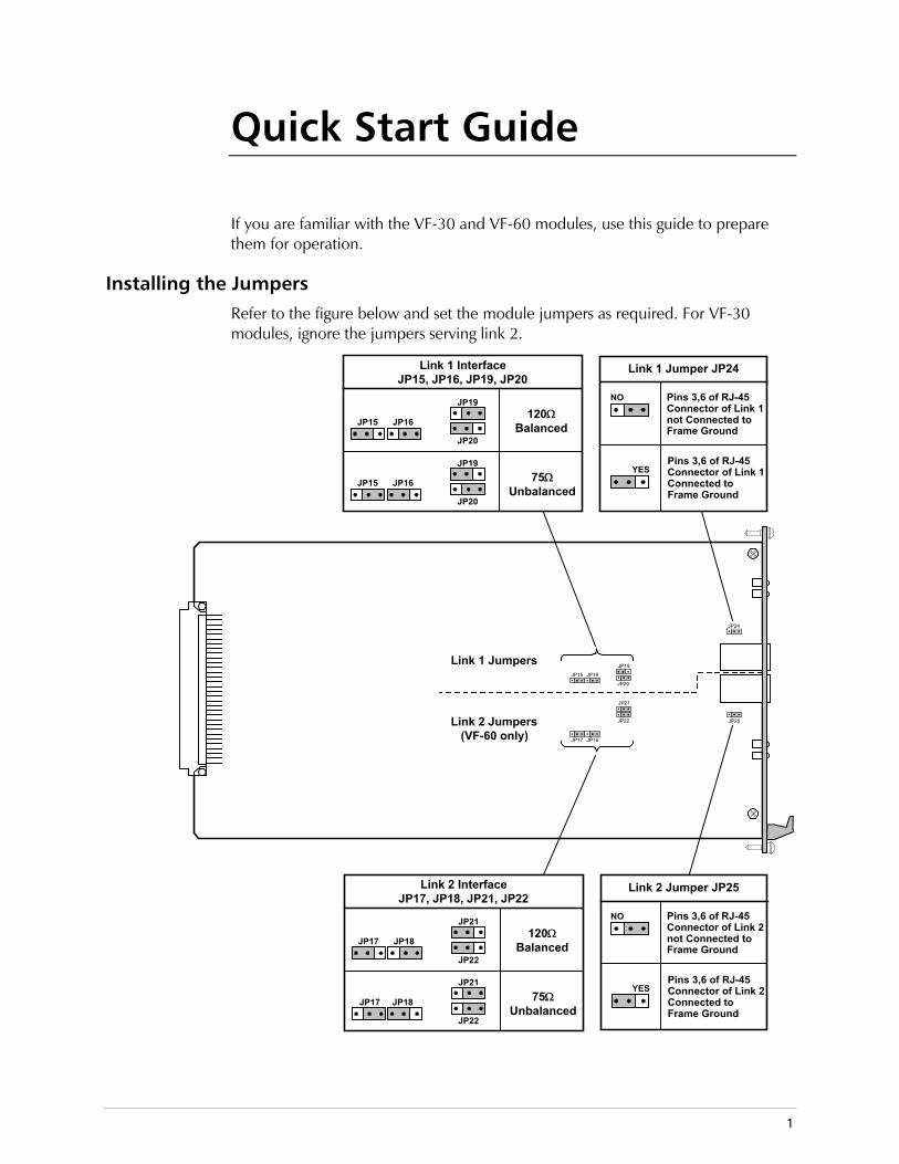
Quick Start Guide If you are familiar with the VF-30 and VF-60 modules, use this guide to prepare them for operation.
Installing the Jumpers Refer to the figure below and set the module jumpers as required. For VF-30 modules, ignore the jumpers serving link 2.
Link 1 Jumpers
JP24
JP25Link 2 Jumpers(VF-60 only)
Link 2 InterfaceJP17, JP18, JP21, JP22
JP17 JP18
JP21
JP22
JP17 JP18
JP21
JP22
120ΩBalanced
75ΩUnbalanced
Link 1 InterfaceJP15, JP16, JP19, JP20
JP15 JP16
JP19
JP20
JP15 JP16
JP19
JP20
120ΩBalanced
75ΩUnbalanced
NO
YESPins 3,6 of RJ-45Connector of Link 2Connected toFrame Ground
Link 2 Jumper JP25
Pins 3,6 of RJ-45Connector of Link 2not Connected toFrame Ground
NO
YESPins 3,6 of RJ-45Connector of Link 1Connected toFrame Ground
Link 1 Jumper JP24
Pins 3,6 of RJ-45Connector of Link 1not Connected toFrame Ground
JP19
JP20
JP15 JP16
JP21
JP22
JP17 JP18
Quick Start Guide VF-30/VF-60 Installation and Operation Manual
2
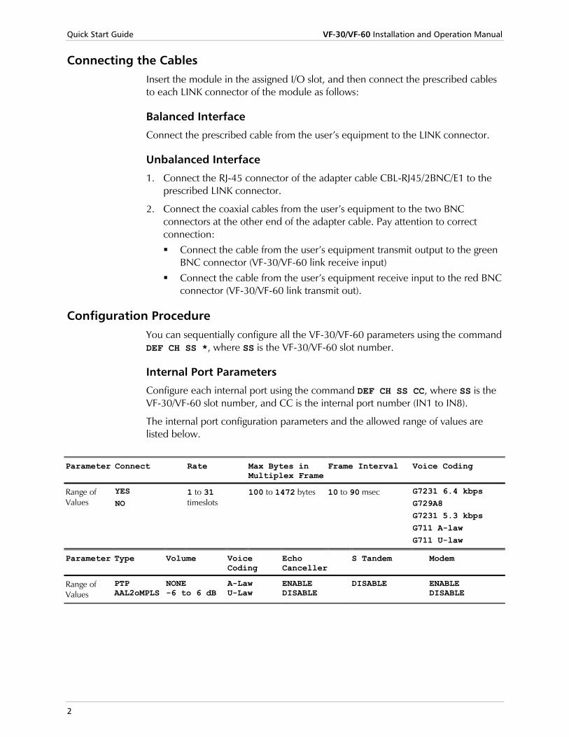
Connecting the Cables Insert the module in the assigned I/O slot, and then connect the prescribed cables to each LINK connector of the module as follows:
Balanced Interface
Connect the prescribed cable from the user’s equipment to the LINK connector.
Unbalanced Interface
1. Connect the RJ-45 connector of the adapter cable CBL-RJ45/2BNC/E1 to the prescribed LINK connector.
2. Connect the coaxial cables from the user’s equipment to the two BNC connectors at the other end of the adapter cable. Pay attention to correct connection: Connect the cable from the user’s equipment transmit output to the green
BNC connector (VF-30/VF-60 link receive input) Connect the cable from the user’s equipment receive input to the red BNC
connector (VF-30/VF-60 link transmit out).
Configuration Procedure You can sequentially configure all the VF-30/VF-60 parameters using the command DEF CH SS *, where SS is the VF-30/VF-60 slot number.
Internal Port Parameters
Configure each internal port using the command DEF CH SS CC, where SS is the VF-30/VF-60 slot number, and CC is the internal port number (IN1 to IN8).
The internal port configuration parameters and the allowed range of values are listed below.
Parameter Connect Rate Max Bytes in
Multiplex FrameFrame Interval Voice Coding
Range of Values
YES NO
1 to 31 timeslots
100 to 1472 bytes 10 to 90 msec G7231 6.4 kbps G729A8 G7231 5.3 kbps G711 A-law G711 U-law
Parameter Type Volume Voice Coding
Echo Canceller
S Tandem Modem
Range of Values
PTP AAL2oMPLS
NONE -6 to 6 dB
A-Law U-Law
ENABLE DISABLE
DISABLE ENABLE DISABLE

VF-30/VF-60 Installation and Operation Manual Quick Start Guide
3
Parameter Fax Rate Inband Management
Routing Protocol Src/Dst Bundle ID Dst IP
Range of Values
Disable 4.8 kbps 9.6 kbps 14.4 kbps
ON OFF
PROPRIETARY RIPN/A
1 to 30 N/A
xxx.xxx.xxx.xxx N/A
Parameter MF Relay Min Pulse Width
Min Power Level ML Slot ML Channel
Range of Values
ENABLE DISABLE
45 to 300 ms
N/A
0 to -35 dB
N/A
MP-2100: 1 to 12
MP-2104: 1 to 4
EX1
EX2
Link Parameters
The links have two types of parameters:
• External E1 port parameters
• Timeslot utilization parameters.
To configure the link parameters, use the command DEF CH SS CC, where SS is the VF-30/VF-60 slot number, and CC is the link number, EX1 or EX2.
The external E1 port configuration parameters and the allowed range of values are listed below.
Parameter Connect Frame Sig. Profile Idle Code Rx Gain OOS Signaling
Range of Values
YES NO
G.732N G.732N-CRC4 G.732S G.732S-CRC4
1 to 5 00 to FF LONG HAUL SHORT HAUL
FORCED BUSY FORCED IDLE
Parameter Restoration Time Inband Management Inband Management Rate
Routing Protocol
Range of Values
CCITT 10 SECONDS (62411) 1 SECOND (FAST)
OFF DEDICATE PPP DEDICATE FR
N/A
64kbps (for DEDICATE FR and DEDICATE PPP)
NONE PROPRIETARY RIP RIP2
The external E1 port timeslot utilization parameters and the allowed range of values are listed below.
Parameter Local
Destination Timeslot Type Remote Destination
Port Remote Destination Timeslot
Range of Values
N.C.
INT01 to INT08 SS:CC:TT
VOICE
CCS
TRANS (for SS:CC:TT only) MNG CCS 1 to CCS 8 SS7 1 to SS7 8
N.C.
EX1 or EX2
N.C.
1 to 31

Quick Start Guide VF-30/VF-60 Installation and Operation Manual
4

Contents
Chapter 1. Introduction 1.1 Overview..................................................................................................................... 1-1
Purpose and Main Features...................................................................................................1-1 Main Features.......................................................................................................................1-1
1.2 Typical Applications..................................................................................................... 1-4 Point-to-Point Applications ...................................................................................................1-4 Point-to-Multipoint Applications ...........................................................................................1-4
1.3 Physical Description..................................................................................................... 1-5 1.4 Functional Description................................................................................................. 1-7
Functional Block Diagram .....................................................................................................1-7 TDM Bus Interfaces ..............................................................................................................1-8 Routing Matrix on TDM Buses Side .......................................................................................1-8 Internal Ports Routing Matrix.................................................................................................1-9 DSP Subsystem.....................................................................................................................1-9 Link Interfaces ....................................................................................................................1-10 Clock Generator and Timing Subsystem ..............................................................................1-10 Local Management Subsystem ............................................................................................1-11 E1 Interface Characteristics .................................................................................................1-11 Handling of Signaling Information .......................................................................................1-12 Audio Signal Processing Capabilities ....................................................................................1-13 Test and Diagnostic Capabilities ..........................................................................................1-15
1.5 Technical Characteristics............................................................................................ 1-16
Chapter 2. Module Installation and Operation 2.1 Introduction................................................................................................................. 2-1 2.2 Preparation for Installation........................................................................................... 2-2
VF-60 Internal Settings ..........................................................................................................2-2 VF-30 Internal Settings ..........................................................................................................2-2
2.3 Installing the Module in the Chassis ............................................................................. 2-3 2.4 Connecting the Cables................................................................................................. 2-4
Connection Data ..................................................................................................................2-4 Connection Instructions ........................................................................................................2-5
2.5 Normal Indications ...................................................................................................... 2-6 Module Status Indication ......................................................................................................2-6 Link Status Indications ..........................................................................................................2-6
Chapter 3. Configuration Instructions 3.1 Overview..................................................................................................................... 3-1 3.2 Outline of Configuration Procedure ............................................................................. 3-1 3.3 VF-30/VF-60 Configuration Instructions ....................................................................... 3-2
Internal Port Parameters........................................................................................................3-2 Link Parameters ....................................................................................................................3-5
3.4 System Timing Considerations ................................................................................... 3-11 3.5 Displaying VF-30/VF-60 Information.......................................................................... 3-11
Displaying Status and Configuration Information .................................................................3-11 Displaying Signaling Information .........................................................................................3-11
VF-30/VF-60 Installation and Operation Manual i

Table of Contents
Chapter 4. Configuring Typical Applications 4.1 Typical Application ...................................................................................................... 4-1 4.2 Configuring the Modules.............................................................................................. 4-2
Chapter 5. Troubleshooting & Diagnostics 5.1 Introduction................................................................................................................. 5-1 5.2 Performance Monitoring .............................................................................................. 5-1
Overview..............................................................................................................................5-1 Internal Port Performance Parameters ...................................................................................5-2
5.3 Test and Diagnostic Functions...................................................................................... 5-3 Loopbacks and Tests on External E1 Ports..............................................................................5-3 Loopbacks on Internal Ports ..................................................................................................5-5
5.4 Troubleshooting the Modules ...................................................................................... 5-6 Troubleshooting New Installations.........................................................................................5-6 General Troubleshooting Procedure ......................................................................................5-7
5.5 Frequently Asked Questions ........................................................................................ 5-7 5.6 Technical Support........................................................................................................ 5-8
ii VF-30/VF-60 Installation and Operation Manual

Overview 1-1
Chapter 1 Introduction
1.1 Overview
Purpose and Main Features VF-30 and VF-60 are digital voice/fax compression modules with E1 interfaces for the Megaplex-2100 and Megaplex-2104 Modular Integrating Access Nodes.
In this manual, the generic term Megaplex is used when the information is applicable to both the Megaplex-2100 and Megaplex-2104 chassis types. The complete designation is used only for information applicable to a specific version.
The voice/fax compression modules are available in two versions that differ with respect to the number of external links (E1 interfaces) installed on the module:
• VF-30: module with one link, supports 30 channels
• VF-60: module with two independent links, supports 30 channels per link for a total of 60 channels per module.
Main Features
Voice Transmission
VF-30/VF-60 modules connect and compress E1 voice trunks for efficient transmission over TDM or IP networks. The timeslots received from the external E1 trunks are compressed using one of the following standard algorithms:
• ITU-T Rec. G.723.1 at 6.4 kbps per channel. This enables transmitting up to 10 voice channels in one timeslot.
• ITU-T Rec. G.723.1 at 5.3 kbps per channel. This enables transmitting up to 12 voice channels in one timeslot.
• ITU-T Rec G.729.A at 8.0 kbps per channel. This enables transmitting up to 8 voice channels in one timeslot.
Compression methods are user-selectable per bundle.
Every six voice timeslots are handled by a single DSP. Each DSP supports one compression method at any time.
Note
Note

Chapter 1 Introduction VF-30/VF-60 Installation and Operation Manual
1-2 Overview
The module includes adaptive echo canceling for near-end hybrid echo, for delays of up to 16 msec. The echo canceller enables acceptable voice quality on voice lines with long delay, such as long-distance calls or calls over non-terrestrial (satellite) links.
To ensure reliable transmission of DTMF signals, they are always transmitted through the link as digital signals (this is called DTMF relaying), and clean representations are synthesized at the receiving end. The same process is used for the call progress tones that are detected within the E1 trunk timeslots.
Automatic Fax and Modem Transmission
In addition to voice transmission, the VF-30/VF-60 modules also support automatic fax relaying, which allows the transmission of Group III fax (ITU-T Rec. V.17 and V.29) at rates of 2.4 to 14.4 kbps, irrespective of the digitizing rate selected for voice.
The modules have automatic rate fallback capability, to automatically switch to the next lower data rate supported by both communicating faxes.
Voiceband modem transmissions at all the standard rates up to 14.4 kbps (per ITU-T Rec. V.22bis and V.32bis) are also supported, and are handled in the same way as fax transmissions.
Transparent Transfer of Timeslots
In addition to timeslots being processed to support voice and fax, it is also possible to transparently transfer selected timeslots of the external trunks through the Megaplex links, to a remote location, thereby providing support for fractional E1 services together with compressed voice through the same E1 trunk.
Another application for transparent transfer of timeslots is support for CCS signaling in any desired protocol or flavor: the timeslot carrying the CCS information can be transferred transparently together with the timeslots carrying the voice channels to the remote Megaplex equipment. This permits restoring the original E1 trunk structure, including the signaling channel, at the external link interface of the remote VF-30/VF-60 module.
Inband management through dedicated timeslots is also supported. Among other options, this enables extending the inband management links, through the E1 interfaces of the module, to other equipment connected to these interfaces.
Traffic Carrying Capacity
The advanced digital signal processing (DSP) techniques used by the VF-30/VF-60 modules provide voice compression options that meet a wide range of user requirements and enable the transmission of high-quality compressed voice signals while requiring low bandwidth.
The number of channels that can be transmitted depends on the percentage of silence the number of simultaneously active calls, and the packet parameters. The number of channels and the approximate bandwidth can be estimated using the following formula:

VF-30/VF-60 Installation and Operation Manual Chapter 1 Introduction
Overview 1-3
[(Header size x packets per second ) + (# tim eslots x size ofcom pressed G .732 packet x 1000/30 x actual transm ission tim e (%
non-silence) )] x 8 bytes per b it
1000 b its per kilob it
+ rateconverted
to kbps
You can also use for this purpose the Vmux-110/2100 Bandwidth calculator supplied on the Megaplex Technical Documentation CD.
Two companding laws are supported, µ-law and A-law. In accordance with ITU-T Rec. G.711, the A-law should be used on E1 trunks and the µ-law should be used on T1 trunks. However, the user can select the desired companding law, µ-law or A-law, in accordance with the specific system requirements.
Since the VF-30/VF-60 modules can compress and transmit multiple E1 trunks using minimal bandwidth, the Megaplex units can utilize the remaining bandwidth to provide other required services such as data, Ethernet LANs, ISDN and/or management, all in one platform.
With regular voice encoding methods, much bandwidth is wasted during the normal periods of silence in a call. To further reduce the actual bandwidth required for voice transmission, the VF-30/VF-60 modules support voice activity detection (VAD) techniques with silence detection and suppression:
• When a silence interval is detected in a channel (timeslot), an indication is sent to the far end, and the transmitting side releases most of the bandwidth normally occupied by the channel traffic.
• The far end fills the interval with noise having characteristics similar to normal background noise (this capability is called comfort noise generation), and therefore the subjective quality of the call is not noticeably affected.
This method enables using less bandwidth to transmit the same amount of voice traffic, without degrading the quality of the call.
The low-rate digitized voice data packets that are the result of digital signal processing of the payload carried by the external port timeslots are routed to internal ports. The VF-30/VF-60 modules support up to 8 internal ports; each internal port can be routed to a different destination through any desired main link port, thereby supporting both point-to-point and point-to-multipoint applications.
The user can therefore select the bandwidth (number of timeslots on the main link) that will be allocated per internal port in accordance with the selected compression rate. By considering the statistical distribution of speech and call traffic loads, even higher compression ratios are possible.

Chapter 1 Introduction VF-30/VF-60 Installation and Operation Manual
1-4 Typical Applications
1.2 Typical Applications
Point-to-Point Applications Figure 1-1 shows a typical point-to-point application for VF-30/VF-60 modules. In this application, a single PBX trunk is connected to a VF-30 module, and the resulting data stream is routed by means of a single internal port, allocated the desired number of timeslots, to a main link port.
The compressed voice data stream is transported through the TDM network to the far end, where it is restored and connected to another PBX. The PBX trunks can use any desired signaling protocol:
• For CAS (G.732S), no special arrangements are needed, as this signaling protocol is processed and transferred by the VF-30 module within the compressed voice data stream.
• For other signaling protocols, for example, protocols using CCS, the timeslots carrying the signaling information can be transparently transferred to the far end in other main link timeslots, and made available to the equipment connected to the far end module.
A single Megaplex-2100 unit can be equipped with up to 10 VF-60 modules, and therefore can support up to 20 E1 trunks (600 digital voice channels). After compression, this payload can be transmitted using only two E1 links, enabling very efficient utilization of the E1 links. Megaplex-2104 units can be equipped with 4 VF-60 modules to support up to 8 E1 trunks.
Figure 1-1. Typical Point-to-Point Application for VF-30/VF-60 Modules
Point-to-Multipoint Applications Point-to-multipoint applications use the multiple internal ports (up to 8) supported by the VF-30/VF-60 modules. Each internal port can operate at a different voice encoding rate and/or fax rate. Each internal port can be routed to a different destination by routing it to a different main link port or IP destination.
Figure 1-2 shows a typical point-to-multipoint application for VF-30/VF-60 modules. In this application, two PBX trunks are connected to a VF-60 module, and the resulting data stream is routed by means of three internal ports, allocated the desired number of timeslots, to a ML-IP module.
The ML-IP module provides independent links to the desired destinations through the IP network.

VF-30/VF-60 Installation and Operation Manual Chapter 1 Introduction
Physical Description 1-5
Figure 1-2. Typical Point-to-Multipoint Application for VF-30/VF-60 Modules
1.3 Physical Description VF-30/VF-60 are 4U-high modules that occupy one slot in the Megaplex chassis. All the module parameters are configurable by software, except for the selection of the link interface type (balanced or unbalanced).
The VF-30/VF-60 module panels are shown in Figure 1-3. The panels include an RJ-45 connector and a group of status indicators for each link, and a module alarm indicator.
Table 1-1 explains the functions of the components located on the module panels.

Chapter 1 Introduction VF-30/VF-60 Installation and Operation Manual
1-6 Physical Description
Table 1-1. VF-30/VF-60 Panels
Component Description
ALARM indicator
Lights when a fault has been detected in the module
ON LINE indicator
Lights steadily when the corresponding link is operating properly and is active (i.e., some of its timeslots are connected to an internal port or bypassed).
Off when the corresponding link is defective, or none of its timeslots is connected to an internal port or bypassed
LOC S. LOSS indicator
Lights when the corresponding local link has lost frame synchronization
REM S. LOSS indicator
Lights when a loss-of-frame synchronization indication is received by the corresponding link from the equipment connected to that link
TST indicator Lights when a test is being performed on the corresponding link
LINK connector
RJ-45 connector for connection to the corresponding link interface
VF-30E1
LINK
S. LOSS
TST
REM
ONLINE
ALARM
LOC
S. LOSS
TST
REM
ONLINE
LOC
VF-60E1
LINK1
S. LOSS
TST
REM
ONLINE
ALARM
LOC
LINK2
VF-30 VF-60
Figure 1-3. VF-30/VF-60 Module Panels

VF-30/VF-60 Installation and Operation Manual Chapter 1 Introduction
Functional Description 1-7
1.4 Functional Description
Functional Block Diagram Figure 1-4 shows the functional block diagram of the VF-30 and VF-60 modules.
VF-30/VF-60
Receive Clock fromLink Interfaces
ClockSelection
Link 1
Internal Clock& Timing Signals
VoiceProcessing
DSP 1
SignalingDSP
ClockGenerator
Main Clock
Fallback Clock
LocalManagement
To CL Module
Control To Link Interfaces
Man
agem
ent
Cha
nnel
Link 2
VoiceProcessing
DSP 2
LinkInterface
(Port EX2)
Nodal Timing
TDM
Bus
B
TDM
Bus
C
TDM
Bus
D
TDM
Bus
A
2
3
4
5
6
7
8
VF-60 OnlyInternalPorts
RoutingMatrix
RoutingMatrix
andTDM BusInterfaces
InternalPorts
1
LinkInterface
(Port EX1)
Figure 1-4. VF-30/VF-60, Functional Block Diagram
The VF-30/VF-60 modules include the following subsystems:
• Routing matrix and TDM bus interfaces
• Internal ports routing matrix

Chapter 1 Introduction VF-30/VF-60 Installation and Operation Manual
1-8 Functional Description
• DSP subsystem
• Link interfaces
• Clock generator and timing subsystem
• Local management subsystem.
TDM Bus Interfaces The VF-30/VF-60 module has four independent TDM bus interfaces, one for each Megaplex TDM bus. Each TDM bus interface is used to connect timeslots from the corresponding bus to the routing matrix of the VF-30/VF-60 module, in accordance with the commands received from the CL module.
Routing Matrix on TDM Buses Side
Overview of Internal Routing Method
To understand the payload routing method used within the VF-30/VF-60 module, it is necessary to consider three entities:
• Chassis TDM buses. The flow of payload on these buses is organized in timeslots (31 timeslots per bus). The CL module automatically assigns timeslots on the TDM buses to each connected I/O channel or internal port of the modules installed in the chassis.
• External ports. The external port, which has an E1 interface, provides the connection to the local user’s equipment. VF-60 modules have two independent external ports.
An external port has a capacity of 31 timeslots. However, since signaling information must always be transmitted, only 30 timeslots can carry voice (one timeslot is always assigned either to CAS or CCS signaling).
• Internal ports. On the TDM buses side, the timeslots that carry voice and fax payload directed for transmission through the VF-30/VF-60 module are formally connected to entities designated internal ports. The VF-30/VF-60 modules can be configured to use up to 8 internal ports.
On the external ports side, the internal ports receive frames containing digitized voice and the associated signaling from the DSP subsystem.
An internal port provides a convenient way to indicate which payload is to be routed to a certain destination, and enables the user to specify associated parameters. For flexibility in routing, the internal ports are located between two routing matrices: the TDM bus side routing matrix, and the internal ports routing matrix.

VF-30/VF-60 Installation and Operation Manual Chapter 1 Introduction
Functional Description 1-9
In addition to packetized payload, it is also necessary to transparently bypass timeslots to a main link port. Bypassing of timeslots is needed to support fractional E1 service through the module links; it may also be used to transparently transfer the common channel signaling (CCS) information received from the user’s equipment connected to the external port to the remote end of the compressed voice link, where the original frame structure and signaling can be restored. The timeslot carrying inband management traffic may also have to be bypassed.
Routing Matrix Functions
The routing of the TDM bus side matrix is user-programmable, under the control of the CL module, and enables connecting any timeslot between of its ports. As a result, the matrix can be used to perform the following functions:
• Connect timeslots between main link ports of modules installed in the Megaplex and the internal ports of the VF-30/VF-60 module. This is performed by connecting the desired timeslots from the TDM buses to the prescribed internal port.
• Bypass timeslots between the external ports of the VF-30/VF-60 module and main link ports (through the internal ports of the VF-30/VF-60 module).
It is not possible to bypass timeslots directly between two VF-30/VF-60 modules.
Internal Ports Routing Matrix The internal ports routing matrix is used to route the packetized voice traffic to timeslots that are then connected by the TDM side routing matrix to the TDM buses.
The internal ports routing matrix is also used to bypass timeslots between the external ports of the VF-30/VF-60 module and main link ports.
DSP Subsystem The DSP subsystem includes two groups of DSPs:
• Voice processing DSPs
• Signaling DSP.
Voice Processing DSP Subsystem
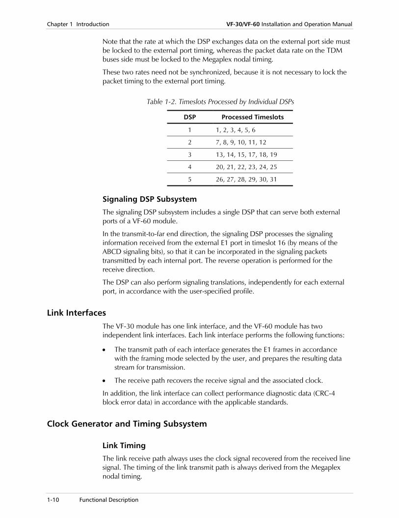
The voice processing DSP subsystem includes five DSPs for each external port. Each DSP processes six timeslots out of the 30 payload timeslots that may be carried by an external port.
The timeslots processed by each DSP are identified in Table 1-2.
Since the DSP performs the same operations on all of the processed timeslots, the six timeslots must use the same voice coding standard and fax rate. The resulting voice packets are sent to the internal ports routing matrix.
Note
Note
Chapter 1 Introduction VF-30/VF-60 Installation and Operation Manual
1-10 Functional Description
Note that the rate at which the DSP exchanges data on the external port side must be locked to the external port timing, whereas the packet data rate on the TDM buses side must be locked to the Megaplex nodal timing.
These two rates need not be synchronized, because it is not necessary to lock the packet timing to the external port timing.
Table 1-2. Timeslots Processed by Individual DSPs
DSP Processed Timeslots
1 1, 2, 3, 4, 5, 6
2 7, 8, 9, 10, 11, 12
3 13, 14, 15, 17, 18, 19
4 20, 21, 22, 23, 24, 25
5 26, 27, 28, 29, 30, 31
Signaling DSP Subsystem
The signaling DSP subsystem includes a single DSP that can serve both external ports of a VF-60 module.
In the transmit-to-far end direction, the signaling DSP processes the signaling information received from the external E1 port in timeslot 16 (by means of the ABCD signaling bits), so that it can be incorporated in the signaling packets transmitted by each internal port. The reverse operation is performed for the receive direction.
The DSP can also perform signaling translations, independently for each external port, in accordance with the user-specified profile.
Link Interfaces The VF-30 module has one link interface, and the VF-60 module has two independent link interfaces. Each link interface performs the following functions:
• The transmit path of each interface generates the E1 frames in accordance with the framing mode selected by the user, and prepares the resulting data stream for transmission.
• The receive path recovers the receive signal and the associated clock.
In addition, the link interface can collect performance diagnostic data (CRC-4 block error data) in accordance with the applicable standards.
Clock Generator and Timing Subsystem
Link Timing
The link receive path always uses the clock signal recovered from the received line signal. The timing of the link transmit path is always derived from the Megaplex nodal timing.

VF-30/VF-60 Installation and Operation Manual Chapter 1 Introduction
Functional Description 1-11
Therefore, the user’s equipment must operate with loopback timing, i.e., it must be configured to lock its transmit timing to the clock signal recovered from the VF-30/VF-60 transmit signal.
System Timing
The VF-30/VF-60 clock generator and timing subsystem provides the clock signals needed by the local module circuits.
In addition, this subsystem can also provide Megaplex nodal main and fallback clock signals, derived from the clock signals recovered from the received line signals by each link interface.
Therefore, the Megaplex nodal timing can be locked to the clock signal recovered from the desired E1 receive signal. This mode is used when the E1 link timing must be determined by the user’s equipment connected to the VF-30/VF-60 interface.
This option is necessary only when timeslots are bypassed from the module links to main link ports, and the user’s equipment cannot be configured to lock its transmit timing to the clock signal recovered from the VF-30/VF-60 transmit signal.
Local Management Subsystem The local management subsystem of the VF-30/VF-60 module controls the operation of all the module circuits, under the control of the CL module.
The management subsystem can also provide an interface between the Megaplex CL module and the external links, to support inband management through a dedicated timeslot when this option is enabled by the user:
• In the receive-from-link direction, the management traffic is extracted from the user-specified timeslot and transferred to the CL module via the Megaplex chassis buses.
• In the transmit to-link direction, the management traffic received from the CL module is inserted in the user-specified timeslot of the link interface, for transmission to the user’s equipment (when it can be managed using one of the protocols supported by Megaplex equipment).
The management traffic can use the PPP or Frame Relay protocols, in addition to the RAD proprietary routing protocol.
E1 Interface Characteristics The E1 interfaces of the VF-30/VF-60 module meet the requirements of ITU-T Rec. G.703, G.704, and G.732. The line code is HDB3. Jitter performance complies with the requirements of ITU-T Rec. G.823.
Each link can be configured by means of internal jumpers to use either of the following types of interfaces:
• 120Ω balanced line interface. The nominal balanced interface transmit level is ±3V.
• 75Ω unbalanced interface. The nominal unbalanced interface transmit level is

Chapter 1 Introduction VF-30/VF-60 Installation and Operation Manual
1-12 Functional Description
±2.37V.
You can select the maximum line attenuation that can be compensated without degrading the BER performance: 12 dB (similar to a DSU) or 36 dB (as required of an LTU).
Each link can be configured to use its own framing mode. The following framing modes are supported:
• G732S (16 frames per multiframe), intended for use with channel-associated signaling (CAS). In most applications, the required signaling mode is CAS: this mode is compatible with the signaling mode used by PBXs.
• G732N (2 frames per multiframe), intended for use with common-channel signaling (CCS) protocols. These protocols exchange the signaling information through a dedicated timeslot and therefore require transparent transmission of the CCS timeslot through the link.
You can configure each interface to operate with or without the CRC-4 option. The use of the CRC-4 option allows monitoring the E1 connection to the user’s equipment.
Handling of Signaling Information
Handling of CAS Signaling
In the CAS mode, the signaling information of all the channels is multiplexed within timeslot 16 of the E1 frames. Each timeslot (channel) is allocated four signaling bits, designated A, B, C, and D. The signaling information of a channel represents, as a minimum, the state of the equipment connected to the channel (on-hook/off-hook).
The signaling information of each channel is processed and transferred in the packets transferred through the internal port serving the corresponding voice channels.
In case the link to the remote VF-30/VF-60 module is out-of-service, the user can select the state of the signaling information sent in all the channels during the out-of-service period:
FORCED BUSY The signaling information is forced to the busy state during out-of-service periods.
FORCED IDLE The signaling information is forced to the idle state during out-of-service periods.
Handling of CCS Signaling
In addition to CAS signaling, the VF-30/VF-60 modules can also support equipment using common-channel signaling (CCS) protocols. These protocols exchange the signaling information through a dedicated channel timeslot and therefore require transparent transmission of the CCS timeslot through the module.
The CCS timeslots can be compressed and transmitted to the destination ports in up to 8 logical groups, CCS<1> to CCS<8>. Timeslots are assigned to logical
VF-30/VF-60 Installation and Operation Manual Chapter 1 Introduction
Functional Description 1-13
groups manually be the user.
Handling of SS7 Signaling
Handling of SS7 signaling timeslots is similar to that of CCS.
Audio Signal Processing Capabilities This section explains the audio processing capabilities of VF-30/VF-60 modules. The audio processing capabilities, which are performed by the digital signal processors (DSPs), include:
• Voice processing
• Processing of DTMF and call progress tones
• Processing of fax and voiceband modem signals.
Each DSP processes its group of timeslots (see Table 1-2) independently of the other DSPs, in accordance with the parameters selected by the user for that group. However, within each group, the DSP detects the signal type (voice, DTMF, fax, etc.) carried in each timeslot (channel), and automatically selects the appropriate processing method.
Handling of Voice Signals
Voice is digitized and compressed using one of the processing algorithms supported by the VF-30/VF-60.
The low bit rate voice compression options and data rates supported by VF-30/VF-60 are as follows:
• Voice compression using multiple-pulse, maximum likelihood code-excited linear prediction (MP-MLQ) per ITU-T Rec. G.723.1, at a channel data rate of 6.4 kbps. When using this option, up to 10 voice channels can be carried by each timeslot sent to the Megaplex TDM buses.
• Voice compression using conjugate structure-algebraic-code-excited linear prediction (CS-ACELP) per Annex A of ITU-T Rec. G.729A, at a channel data rate of 8 kbps. When using this option, up to 8 voice channels can be carried by each timeslot sent to the Megaplex TDM buses.
To further reduce the bandwidth needed to transmit the voice, the VF-30/VF-60 DSP recognizes “silence” intervals and replaces them with special “silence” packets, that require much less bandwidth than regular voice packets. When “silence” packets are received, the comfort noise generator (CNG) of the remote channel generates background noise to fill the silence intervals and give the remote subscriber the impression of a live line.
The resulting channel data stream is packetized for transmission through the network. The user can select two parameters:
• The maximum number of bytes included in each voice coder frame (100 to 450 bytes). This limits the size of packets sent to the network.
• The maximum interval between consecutive frames: if this interval expires, the

Chapter 1 Introduction VF-30/VF-60 Installation and Operation Manual
1-14 Functional Description
frame is closed and sent, even if the specified maximum number of bytes has not yet been collected. This parameter ensures that the end-to-end delay is not excessive, for example, the additional delay needed to collect timeslots to fill a frame from an internal port that carries a single channel (timeslot), even for the minimum frame length (100 bytes) is approx. 12.5 msec.
Because the DSP sends only data packets toward the Megaplex TDM buses, and packets can be read and transmitted independently of the rate of the incoming E1 stream, in general it is not necessary to lock the timing of the link interface to the Megaplex timing. The timing must be locked only when the module transfers (bypasses) timeslots transparently.
To improve the perceived link quality, the DSPs also implement adaptive echo canceling for near-end reflections (echo delay less than 16 milliseconds). The echo canceling performance complies with ITU-T Rec. G.168 requirements.
DTMF Processing
The waveform of the DTMF signals is very different from speech waveforms, therefore most compression algorithms distort DTMF signals to the point that errors occur in the detection of the dialed digits when the DTMF signals are transmitted as analog signals through a compressed voice channel.
To enable reliable transmission of DTMF signals, the VF-30/VF-60 module uses DTMF relaying. For this purpose, each DSP detects incoming DTMF signals, independently for each timeslot, and identifies the dialed digits. The digits detected by the receiving end are digitally transmitted through the link to the remote end, where clean digital representations of DTMF signals are synthesized and inserted into the data stream sent in the corresponding timeslot.
While DTMF information is received, the voice path is disconnected, to prevent interference by signals transmitted through the regular processing path.
The method used for DTMF relaying is also used to transfer transparently call progress tones.
Automatic Fax Processing
The processing of audio signals by low bit rate voice compression methods does not enable analog transmission of fax signals. Therefore, when it is possible that fax machines may be connected to an VF-30/VF-60 voice channel, it is necessary to enable the automatic fax relaying function on that channel.
When automatic fax relaying is enabled, a VF-30/VF-60 channel will automatically recognize and transmit fax messages at the standard rates in the range of 2.4 to 14.4 kbps, complying with ITU-T Rec. V.17 and V.29. The maximum fax rate can be selected by the user. The VF-30/VF-60 supports automatic fallback capability, that is, it will automatically switch to the next lower data rate supported by both communicating faxes.
The whole fax transmission process is handled as a data transmission, with the corresponding DSP providing the fax signal modulation/demodulation functions
Note
VF-30/VF-60 Installation and Operation Manual Chapter 1 Introduction
Functional Description 1-15
and the detection and generation of the fax connection set up tones (in digital format), to enable the handshaking necessary to implement the standard fax communication protocol. Fax transmission over the digital network improves transmission quality, while greatly reducing long distance telephone costs and the time needed for freeing the fax machine.
To set up a fax connection, the DSP processing the local timeslot (channel) emulates the remote fax machine toward the local machine, and the remote DSP emulates the local fax toward the remote machine. After the fax connection is established, the fax data stream is transmitted as a packetized data stream through the link. This means that the link must have enough free bandwidth to enable sustained transmission of a data stream at the fax data rate (and the additional connection supervision signals).
This process enables any standard Group III fax machine to transmit over the link. The only limitation is that the round-trip transmission delay through the link cannot exceed the time-out intervals specified by the fax communication protocol (about 700 msec); otherwise, the handshaking needed to establish a fax connection will fail.
Since each VF-30/VF-60 channel automatically switches between the fax relay mode and the voice mode in accordance with the type of signal being detected, VF-30/VF-60 modules can serve PBX tie lines or channels serving a combined phone/fax machine.
Handling of Voiceband Modem Signals
The DSPs can also handle voiceband modem signals, in accordance with ITU-T Rec. V.22bis and V.32bis. The processing method is similar, except that the DSP emulates a voiceband modem instead of a fax modem.
Test and Diagnostic Capabilities The VF-30/VF-60 supports the following user-initiated loopback functions:
• External E1 ports. The loopback functions available at the external E1 port level include:
Local loopback toward the Megaplex TDM buses
Remote loopback toward the user’s equipment connected to the port.
• Internal ports. The internal ports support the local loopback toward the Megaplex TDM buses.

Chapter 1 Introduction VF-30/VF-60 Installation and Operation Manual
1-16 Technical Characteristics
1.5 Technical Characteristics
General Number of External Ports
VF-30 One E1 port
VF-60 Two E1 ports
Number of Internal Ports Eight
Voice Encoding Voice Digitizing Technique • MP-MLQ per ITU-T Rec. G.723.1, at a channel data rate of 6.4 kbps or 5.3 kbps
• Conjugate structure-algebraic-code-excited linear prediction (CS-ACELP) per Annex A of ITU-T Rec. G.729A, at a channel data rate of 8 kbps
Fax Support Fax Data Rates 4.8, 9.6 and 14.4 kbps, selectable per internal port
Number of Ports • VF-30: 1
• VF-60: 2
Voice Channels Supported Up to 30 (per port)
Format E1, 2.048 Mbps
Standard Compliance ITU-T Rec. G.703, G.704, G.732
E1 Interface Characteristics
Framing • G.732N
• G.732N with CRC-4
• G.732S
• G.732S with CRC-4
Interface • 120Ω, 4-wire balanced
• 75Ω, coaxial unbalanced
Line Code HDB3
Signal Levels
Transmit • Balanced : ±3V ±10%
• Unbalanced: ±2.73V ±10%
Receive • 0 to -12 dB for short-haul applications (DSU)
• 0 to -36 dB for long-haul applications (LTU)
Jitter Performance Per ITU-T Rec. G.823

VF-30/VF-60 Installation and Operation Manual Chapter 1 Introduction
Technical Characteristics 1-17
Timing Mode • Transmit clock derived from Megaplex nodal clock
• Receive clock recovered from the receive signal, can be selected as timing reference for Megaplex nodal clock
Connectors • Balanced: 8-pin RJ-45
• Unbalanced: Two BNC coaxial connectors, via adapter cable
Bandwidth Allocation on Trunk
Selectable, according to the programmed voice encoding rate
Channel Bit Error Rate
1 x 10⁻³ or better
Echo path length Maximum 16 msec
Echo return loss enhancement (ERLE)
Better than 30 dB
Adaptive Echo Canceller
Convergence speed Better than ITU-T Rec. G.168
Diagnostics Module Level Automatic self-test upon power-up and continuous monitoring during normal operation
Each E1 Interface • Local loopback toward Megaplex TDM buses
• Remote loopback toward the user’s equipment connected to the port
Each Internal Port • Local loopback towards Megaplex TDM buses
Indicators Per Module Alarm
Per E1 Interface • On-line
• Local sync loss
• Remote sync loss
• Test
Configuration Programmable via the Megaplex management system

Chapter 1 Introduction VF-30/VF-60 Installation and Operation Manual
1-18 Technical Characteristics

Chapter 2 Module Installation and Operation
2.1 Introduction
This Chapter provides installation and operation instructions for the VF-30/VF-60 modules.
The information presented in this Chapter supplements the Megaplex-2100 installation, configuration and operation instructions contained in the Megaplex-2100 Installation and Operation Manual.
Before performing any internal settings, adjustment, maintenance, or repairs, first disconnect all the cables from the module, and then remove the module from the Megaplex enclosure. No internal settings, adjustment, maintenance, and repairs may be performed by either the operator or the user; such activities may be performed only by a skilled technician who is aware of the hazards involved. Always observe standard safety precautions during installation, operation, and maintenance of this product.
Warning
Caution The VF-30/VF-60 modules contain components sensitive to electrostatic discharge (ESD). To prevent ESD damage, always hold the module by its sides, and do not touch the module components or connectors.
Introduction 2-1

Chapter 2 Module Installation and Operation VF-30/VF-60 Installation and Operation Manual
2.2 Preparation for Installation
The operating mode of the VF-30/VF-60 module is controlled by software.
In addition, there are several jumpers that select the hardware operating mode, and these may have to be set before installing a module in the Megaplex enclosure.
VF-60 Internal Settings Figure 2-1 shows the location of the internal jumpers located on the VF-60 module. Table 2-1 describes the jumper functions, and lists the factory (default) settings. If the current settings meet your specific requirements, you may skip this section and proceed with the installation of the module in the equipment enclosure, as explained in Section 2.3.
In addition to the user-selectable jumpers, the VF-60 module includes additional jumpers that are preset by the manufacturer and must not be moved.
Table 2-1. VF-60 Module Internal Jumpers
Jumper Function
Link Interfaces
Link 1: JP15, JP16, JP19, JP20
Link 2: JP17, JP18, JP21, JP22
Each group of jumpers selects the corresponding main link interface:
BAL 120Ω balanced interface.
UNBAL 75Ω unbalanced interface. When using this interface, you may use the CBL-RJ45/2BNC/E1 adapter cable available from RAD to convert the RJ-45 connector to two BNC connectors.
Default setting: BAL
Link 1: JP24
Link 2: JP25
Controls the connection of the frame ground to pins 3, 6 in the corresponding RJ-45 link connector:
YES Connected.
NO Not connected.
Default setting: YES
VF-30 Internal Settings The VF-30 module includes only one link, therefore use the information given above for the VF-60 module but ignore the link 2 settings.
2-2 Preparation for Installation

VF-30/VF-60 Installation and Operation Manual Chapter 2 Module Installation and Operation
Link 1 Jumpers
JP24
JP25Link 2 Jumpers(VF-60 only)
Link 2 InterfaceJP17, JP18, JP21, JP22
JP17 JP18
JP21
JP22
JP17 JP18
JP21
JP22
120ΩBalanced
75ΩUnbalanced
Link 1 InterfaceJP15, JP16, JP19, JP20
JP15 JP16
JP19
JP20
JP15 JP16
JP19
JP20
120ΩBalanced
75ΩUnbalanced
NO
YESPins 3,6 of RJ-45Connector of Link 2Connected toFrame Ground
Link 2 Jumper JP25
Pins 3,6 of RJ-45Connector of Link 2not Connected toFrame Ground
NO
YESPins 3,6 of RJ-45Connector of Link 1Connected toFrame Ground
Link 1 Jumper JP24
Pins 3,6 of RJ-45Connector of Link 1not Connected toFrame Ground
JP19
JP20
JP15 JP16
JP21
JP22
JP17 JP18
Figure 2-1. VF-30/VF-60 Modules, Internal Jumpers
2.3 Installing the Module in the Chassis
The VF-30/VF-60 modules can be installed in an operating chassis (hot insertion).
For general installation procedures and safety instructions, refer to the Megaplex-2100 Installation and Operation Manual.
Insert the VF-30/VF-60 module in the prescribed I/O slot and fasten it with its two screws.
Installing the Module in the Chassis 2-3

Chapter 2 Module Installation and Operation VF-30/VF-60 Installation and Operation Manual
2.4 Connecting the Cables
Connection Data This section provides connection data for the VF-30/VF-60 modules.
Connector Data
Each link interface of a VF-30/VF-60 module is terminated in a shielded RJ-45 connector wired in accordance with Table 2-2.
Table 2-2. Link Interface Connector, Pin Functions
Pin Function
1 Receive pair – ring
2 Receive pair – tip
3 Frame ground (connection controlled by internal jumper)
4 Transmit pair – ring
5 Transmit pair – tip
6 Frame ground (connection controlled by internal jumper)
7, 8 Not connected
E1 Adapter Cable, CBL-RJ45/2BNC/E1
When the VF-30/VF-60 uses unbalanced E1 interfaces, it is necessary to convert each VF-30/VF-60 RJ-45 connector to the standard pair of BNC female connectors used by unbalanced E1 interfaces.
For this purpose, RAD offers a 15-cm long adapter cable, CBL-RJ45/2BNC/E1, which has one RJ-45 plug for connection to a VF-30/VF-60 LINK connector and two BNC female connectors at the other end. Cable wiring is given in Figure 2-2.
2-4 Connecting the Cables

VF-30/VF-60 Installation and Operation Manual Chapter 2 Module Installation and Operation
RJ-45
BNCFemale
Receive(Green)
Transmit(Red)
1
2
3
4
5
6
7
8
ShieldedRJ-45
Transmit(Red BNC)
Receive(Green BNC)
RX Ring
RX Tip
NC
TX Ring
TX Tip
NC
NC
NC
...
...
Figure 2-2. E1 Adapter Cable, CBL-RJ45/2BNC/E1, Wiring Diagram
Connection Instructions Before starting, refer to the installation plan to determine the cables intended for connection to this VF-30/VF-60 module.
To connect the balanced interface:
• Connect the user’s equipment to the prescribed VF-30/VF-60 RJ-45 connectors marked LINK1 and LINK2.
When connecting a VF-30/VF-60 link connector to equipment having an unbalanced interface, it is necessary to use an adapter cable terminated in two BNC connectors. You may use for this purpose the CBL-RJ45/2BNC/E1 cable, offered by RAD.
To connect the unbalanced interface:
1. Connect the RJ-45 connector of the adapter cable CBL-RJ45/2BNC/E1 to the prescribed LINK connector.
2. Connect the coaxial cables from the user’s equipment to the two BNC connectors at the other end of the adapter cable. Pay attention to correct connection: Connect the cable from the user’s equipment transmit output to the green
BNC connector (VF-30/VF-60 link receive input)
Connect the cable from the user’s equipment receive input to the red BNC connector (VF-30/VF-60 link transmit output).
Connecting the Cables 2-5

Chapter 2 Module Installation and Operation VF-30/VF-60 Installation and Operation Manual
2.5 Normal Indications
Module Status Indication When an VF-30/VF-60 main link interface is operational, its ALARM indicator must be off.
Link Status Indications The status of each VF-30/VF-60 link is indicated by a separate set of indicators. The normal indications for an operational link interface are as follows:
• The ON-LINE indicator of an active link must light steadily.
• The TST indicator must be off, but may turn on when a test loop is activated on the corresponding link interface.
• If the other communication equipment on the link is not yet operative, the corresponding LOC S. LOSS and/or REM S. LOSS indicator may light. These indicators must turn off as soon as the link with the remote equipment is established.
2-6 Normal Indications

Outline of Configuration Procedure 3-1
Chapter 3 Configuration Instructions
3.1 Overview
This chapter provides specific configuration information for VF-30/VF-60 modules. The procedures used to select these parameters depend on the management system used to control the Megaplex unit.
The instructions appearing in this chapter assume that you are familiar with the management system being used:
• Supervision terminal or Telnet (covered by the Megaplex-2100 Installation and Operation Manual).
• Network management system, e.g., the RADview network management system (refer to the RADview User's Manual for instructions).
This Chapter covers only the configuration activities specific to VF-30/VF-60 modules. For general instructions and additional configuration procedures, refer to Chapter 5, Chapter 7 and Appendix F of the Megaplex-2100 Installation and Operation Manual.
3.2 Outline of Configuration Procedure
The configuration procedure of a new VF-30/VF-60 module includes the following main steps:
• Inclusion of a VF-30 or VF-60 module not yet installed in the Megaplex into the database. This allows preprogramming the module parameters, so that when the module is installed in the enclosure, it will immediately start operating in the desired mode. This function is performed by means of the DEF SYS command.
You may also have to use the DEF SYS command to configure the system timing when the new module is supposed to provide the timing reference.
• Configuration of module parameters – use the DEF CH SS * command. The VF-30/VF-60 modules have three types of configuration parameters: Internal port parameters External port parameters for each link Timeslot utilization for each link.
Before configuring the VF-30/VF-60 module, it is necessary to define the appropriate signaling profiles, using the DEF PROFILE command.
Note
Chapter 3 Configuration Instructions VF-30/VF-60 Installation and Operation Manual
3-2 VF-30/VF-60 Configuration Instructions
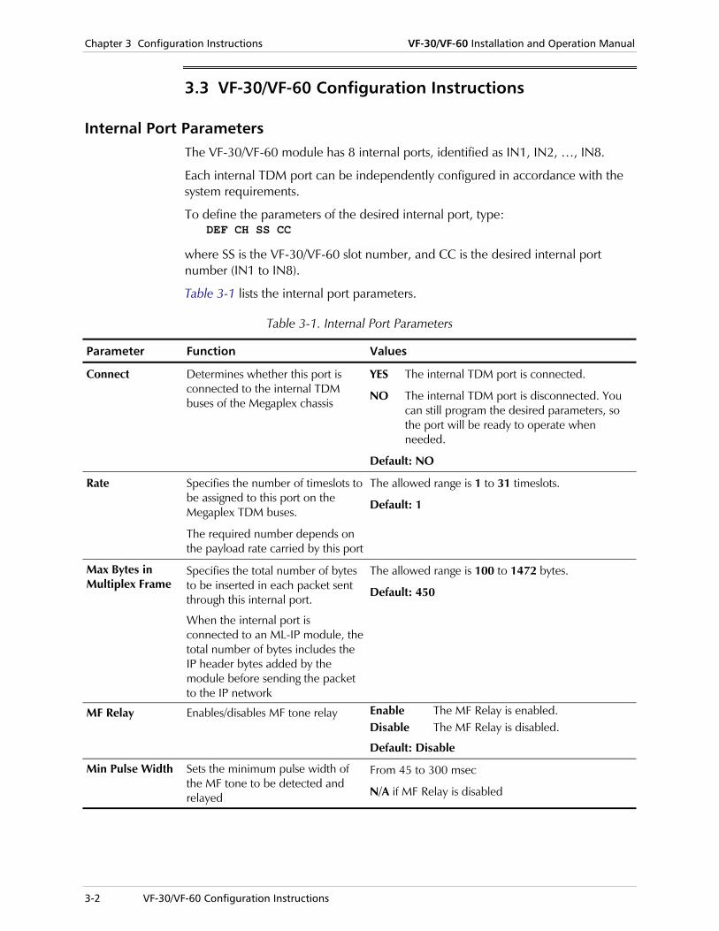
3.3 VF-30/VF-60 Configuration Instructions
Internal Port Parameters The VF-30/VF-60 module has 8 internal ports, identified as IN1, IN2, …, IN8.
Each internal TDM port can be independently configured in accordance with the system requirements.
To define the parameters of the desired internal port, type: DEF CH SS CC
where SS is the VF-30/VF-60 slot number, and CC is the desired internal port number (IN1 to IN8).
Table 3-1 lists the internal port parameters.
Table 3-1. Internal Port Parameters
Parameter Function Values
Connect Determines whether this port is connected to the internal TDM buses of the Megaplex chassis
YES The internal TDM port is connected.
NO The internal TDM port is disconnected. You can still program the desired parameters, so the port will be ready to operate when needed.
Default: NO
Rate Specifies the number of timeslots to be assigned to this port on the Megaplex TDM buses.
The required number depends on the payload rate carried by this port
The allowed range is 1 to 31 timeslots.
Default: 1
Max Bytes in Multiplex Frame
Specifies the total number of bytes to be inserted in each packet sent through this internal port.
When the internal port is connected to an ML-IP module, the total number of bytes includes the IP header bytes added by the module before sending the packet to the IP network
The allowed range is 100 to 1472 bytes.
Default: 450
MF Relay Enables/disables MF tone relay
Enable The MF Relay is enabled. Disable The MF Relay is disabled.
Default: Disable
Min Pulse Width Sets the minimum pulse width of the MF tone to be detected and relayed
From 45 to 300 msec
N/A if MF Relay is disabled

VF-30/VF-60 Installation and Operation Manual Chapter 3 Configuration Instructions
VF-30/VF-60 Configuration Instructions 3-3
Table 3-1. Internal Port Parameters (Cont.)
Parameter Function Values
Min Power Level Sets the minimum power level of the MF tone to be detected and relayed
From 0 to –35 dBm
N/A if MF Relay is disabled
Frame Interval Specifies the maximum time to wait before sending an outgoing packet through this internal port.
When the specified interval expires, the current packet is immediately transmitted, even if the specified maximum number of bytes has not yet been reached
The allowed range is 10 to 90 msec in 10 msec steps.
Default: 30 msec
Voice Coding Selects the coder used by this internal port, and the resulting digitized voice data rate.
See also the considerations presented in the Timeslot Utilization Parameters section below
G7231 6.4 kbps – Coder complying with ITU-T Rec. G.723.1, operating at a data rate of 6.4 kbps.
G7231/5.3 kbps – Coder complying with ITU-T Rec. G.723.1, operating at a data rate of 5.3 kbps.
G729A8 Coder complying with ITU-T Rec G.729.A, operating at a data rate of 8.0 kbps
G711 A-law – Coder complying with ITU-T Rec. G.711, A-law.
G711 U-law – Coder complying with ITU-T Rec. G.711, μ-law.
Default: G7231 6.4 kbps
Type Enables/disables operating with RAD’s Vmux-110 and Vmux-2100 devices
PTP – Point-to-point mode, set for operating opposite VF-24/48 or VF-30/60 modules
AAL2oMPLS – Uses the AAL2oMPLS protocol to transmit the voice and data over the network, set for operating opposite Vmux-110 or Vmux-2100
Default: PTP
Volume Sets the volume gain transmitted from the DSPs towards the PBX. For example, if the gain received from the remote voice switch/PBX is very low, you may set the volume to +3 dB, thereby amplifying the TX voice volume without the need to change the configuration of the voice switch.
NONE No volume gain
From -6 dB to +6 dB in steps of 1 dB.
Default: NONE

Chapter 3 Configuration Instructions VF-30/VF-60 Installation and Operation Manual
3-4 VF-30/VF-60 Configuration Instructions
Table 3-1. Internal Port Parameters (Cont.)
Parameter Function Values
Coding Law Sets the coding used by your PBX
A-Law A-Law coding
U-Law μ-law coding
Default: A-Law
Echo Canceller Enables/disables the built-in echo canceller, which supports up to a 32 msec delay.
If you have an external echo canceller on your telephone network, disable the built-in DSP echo canceller.
Enable The built-in canceller is enabled. Disable The built-in canceller is disabled.
Default: Disable
Modem Enables/disables modem transmission
Enable Modem transmission is enabled. Disable Modem transmission is disabled.
Default: Disable
S Tandem Enables/disables Vmux Super Tandem mechanism
Disable Currently only this value is possible.
Default: Disable
Fax Rate Determines the maximum fax transmission rate (all the other standard rates lower than the selected maximum are also supported).
See also the considerations presented in the Timeslot Utilization Parameters section below
Disable Fax transmission disabled. 4.8 kbps Maximum fax rate of 4.8 kbps. 9.6 kbps Maximum fax rate of 9.6 kbps. 14.4 kbps Maximum fax rate of 14.4 kbps. Default: Disable
Inband Management
Controls the transfer of inband management traffic through this internal port.
OFF The transfer of management traffic is disabled.
ON The transfer of management traffic is enabled.
Default: OFF
Routing Protocol Controls the inband management protocol.
PROPRIETARY RIP RAD proprietary routing protocol (set up automatically when inband management is enabled)
N/A Displayed automatically when inband management is disabled.
Default: OFF
VF-30/VF-60 Installation and Operation Manual Chapter 3 Configuration Instructions
VF-30/VF-60 Configuration Instructions 3-5
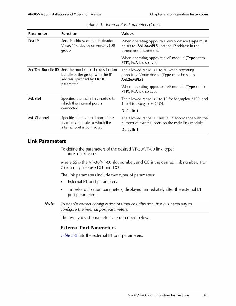
Table 3-1. Internal Port Parameters (Cont.)
Parameter Function Values
Dst IP Sets IP address of the destination Vmux-110 device or Vmux-2100 group
When operating opposite a Vmux device (Type must be set to AAL2oMPLS), set the IP address in the format xxx.xxx.xxx.xxx.
When operating opposite a VF module (Type set to PTP), N/A is displayed
Src/Dst Bundle ID Sets the number of the destination bundle of the group with the IP address specified by Dst IP parameter
The allowed range is 1 to 30 when operating opposite a Vmux device (Type must be set to AAL2oMPLS)
When operating opposite a VF module (Type set to PTP), N/A is displayed
ML Slot Specifies the main link module to which this internal port is connected
The allowed range is 1 to 12 for Megaplex-2100, and 1 to 4 for Megaplex-2104.
Default: 1
ML Channel Specifies the external port of the main link module to which this internal port is connected
The allowed range is 1 and 2, in accordance with the number of external ports on the main link module.
Default: 1
Link Parameters To define the parameters of the desired VF-30/VF-60 link, type:
DEF CH SS:CC
where SS is the VF-30/VF-60 slot number, and CC is the desired link number, 1 or 2 (you may also use EX1 and EX2).
The link parameters include two types of parameters:
• External E1 port parameters
• Timeslot utilization parameters, displayed immediately after the external E1 port parameters.
To enable correct configuration of timeslot utilization, first it is necessary to configure the internal port parameters.
The two types of parameters are described below.
External Port Parameters
Table 3-2 lists the external E1 port parameters.
Note

Chapter 3 Configuration Instructions VF-30/VF-60 Installation and Operation Manual
3-6 VF-30/VF-60 Configuration Instructions
Table 3-2. External E1 Port Parameters
Parameter Function Values
Connect Determines whether the E1 port is connected to the internal signal processing circuits
YES E1 port is connected.
NO E1 port is disconnected. You can still program the desired parameters, so the E1 port will be ready to operate when needed.
Default: NO
Frame Determines the framing mode for this E1 port.
Whenever possible, select a framing mode that supports the CRC-4 function. This enables the collection of performance diagnostic data
G.732N 256N multiframe per ITU-T Rec. G.704 (2 frames per multiframe), CRC-4 function disabled.
G.732N-CRC4 256N multiframe per ITU-T Rec. G.704 (2 frames per multiframe), CRC-4 function enabled.
G.732S 256S multiframe per ITU-T Rec. G.704 (16 frames per multiframe), CRC-4 function disabled.
G.732S-CRC4 256S multiframe per ITU-T Rec. G.704 (16 frames per multiframe), CRC-4 function enabled.
Default: G.732S
Sig. Profile Selects the signaling profile that specifies the interpretation of the signaling information transmitted and received by the corresponding link. When the profile has been assigned a name, the number of the profile appears in brackets, after the profile name. The signaling profiles and their names are defined by means of the DEF PROFILE command. This parameter is not relevant when using the G.732N or G.732N-CRC4 frame
The available range is 1 through 5.
Default: 1

VF-30/VF-60 Installation and Operation Manual Chapter 3 Configuration Instructions
VF-30/VF-60 Configuration Instructions 3-7
Table 3-2. External E1 Port Parameters (Cont.)
Parameter Function Values
Idle Code Selects the code transmitted to fill idle (unused) timeslots in the frames transmitted through this link toward user’s equipment
The available selections are 00 to FF (hexa).
Default: FF
Rx Gain Determines the maximum attenuation of the receive signal that can be compensated for by the port receive path, to obtain the BER performance required by the standards
LONG HAUL Maximum attenuation of 30 dB, relative to the nominal transmit level (0 dB).
SHORT HAUL Maximum attenuation of 12 dB, relative to the nominal transmit level (0 dB).
The lower attenuation may actually improve the performance when operating over relatively short line sections, especially when operating over multi-pair cables. In such cables, significant interference is generated by the signals carried by other pairs, and therefore a weak desired signal may be masked by the interference.
Default: SHORT HAUL
OOS Signaling
Determines the state of the signaling bits during out-of-service periods.
This parameter is not relevant when using the G.732N or G.732N-CRC4 frame
FORCED BUSY The signaling bits are forced to the busy state during out-of-service periods.
FORCED IDLE The signaling bits are forced to the idle state during out-of-service periods.
Default: FORCED IDLE
Restoration Time
Used to change the frame synchronization algorithm, to reduce the time required for the E1 port to return to normal operation after local loss of synchronization
CCITT Complies with ITU-T Rec. G.732. 10 SECONDS Similar to the requirements of AT&T (62411) TR-62411 (after 10 seconds). 1 SECOND After 1 second. (FAST)
Default: 1 SECOND (FAST)
Chapter 3 Configuration Instructions VF-30/VF-60 Installation and Operation Manual
3-8 VF-30/VF-60 Configuration Instructions
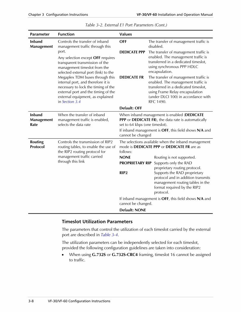
Table 3-2. External E1 Port Parameters (Cont.)
Parameter Function Values
Inband Management
Controls the transfer of inband management traffic through this port.
Any selection except OFF requires transparent transmission of the management timeslot from the selected external port (link) to the Megaplex TDM buses through this internal port, and therefore it is necessary to lock the timing of the external port and the timing of the external equipment, as explained in Section 3.4
OFF The transfer of management traffic is disabled.
DEDICATE PPP The transfer of management traffic is enabled. The management traffic is transferred in a dedicated timeslot, using synchronous PPP HDLC encapsulation.
DEDICATE FR The transfer of management traffic is enabled. The management traffic is transferred in a dedicated timeslot, using Frame Relay encapsulation (under DLCI 100) in accordance with RFC 1490.
Default: OFF
Inband Management Rate
When the transfer of inband management traffic is enabled, selects the data rate
When inband management is enabled (DEDICATE PPP or DEDICATE FR), the data rate is automatically set to 64 kbps (one timeslot). If inband management is OFF, this field shows N/A and cannot be changed
Routing Protocol
Controls the transmission of RIP2 routing tables, to enable the use of the RIP2 routing protocol for management traffic carried through this link
The selections available when the inband management mode is DEDICATE PPP or DEDICATE FR are as follows: NONE Routing is not supported. PROPRIETARY RIP Supports only the RAD
proprietary routing protocol. RIP2 Supports the RAD proprietary
protocol and in addition transmits management routing tables in the format required by the RIP2 protocol.
If inband management is OFF, this field shows N/A and cannot be changed.
Default: NONE
Timeslot Utilization Parameters
The parameters that control the utilization of each timeslot carried by the external port are described in Table 3-4.
The utilization parameters can be independently selected for each timeslot, provided the following configuration guidelines are taken into consideration:
• When using G.732S or G.732S-CRC4 framing, timeslot 16 cannot be assigned to traffic.

VF-30/VF-60 Installation and Operation Manual Chapter 3 Configuration Instructions
VF-30/VF-60 Configuration Instructions 3-9
• The voice timeslots of each external E1 port are processed in groups of 6 consecutive timeslots (skipping timeslot 16), as listed in Table 3-3. Therefore, when selecting timeslots for connection to an internal port, make sure that all the timeslots included in any given group are configured to the same Voice Coding and Fax Rate values.
• When inband management is enabled for the external E1 port being configured (DEDICATE PPP or DEDICATE FR), you must also assign a timeslot to the inband management traffic.
• When bypassing a timeslot for transparent transmission through a main link port, you can select as local destination only one of the free timeslots on a main link port that has already been configured and connected.
• The information regarding the remote destination (remote VF-30/VF-60 port and timeslot) specified by you must match the configuration defined on the remote VF-30/VF-60 module.
Table 3-3. Timeslot Groups with Respect to Voice Coding and Fax Rate Parameters
External E1 Port Group Timeslots
1 1, 2, 3, 4, 5, 6
2 7, 8, 9, 10, 11, 12
3 13, 14, 15, 17, 18, 19
4 20, 21, 22, 23, 24, 25
1
5 26, 27, 28, 29, 30, 31
6 1, 2, 3, 4, 5, 6
7 7, 8, 9, 10, 11, 12
8 13, 14, 15, 17, 18, 19
9 20, 21, 22, 23, 24, 25
2 (VF-60 only)
10 26, 27, 28, 29, 30, 31

Chapter 3 Configuration Instructions VF-30/VF-60 Installation and Operation Manual
3-10 VF-30/VF-60 Configuration Instructions
Table 3-4. External E1 Port Timeslot Utilization Parameters
Parameter Function Values
Local Destination
Determines the internal routing of the corresponding timeslot.
The timeslot may be connected either to an internal port, or bypassed to a selected main link port.
When the timeslot is bypassed, it is necessary to lock the timing of the external VF-30/VF-60 port and the timing of the external equipment, as explained in Section 3.4
N.C. The timeslot is not connected. In this case, the VF-30/VF-60 module sends the selected idle code in this timeslot.
INT01 to The timeslot is connected to the selected INT08 internal port.
SS:CC:TT The timeslot is bypassed transparently to a selected main link timeslot. SS stands for the main link module slot, CC stands for the external port and TT stands for the timeslot number of the selected external port of the main link port.
Default: N.C.
Timeslot Type Determines the handling of the corresponding timeslot
VOICE The timeslot payload is processed by the voice DSP in accordance with the selected Voice Coding parameter.
TRANS The timeslot payload is transparently transferred. This selection is automatically displayed when the timeslot is bypassed and cannot be changed.
MNG The timeslot carries inband management. This option is available only when inband management is enabled.
CCS<x> The timeslot carries CCS signaling data belonging to logical group x, x=1,…,8.
SS7<x> The timeslot carries SS7 signaling data belonging to logical group x, x=1,…,8.
Default: VOICE
Remote Destination Port
Specifies the external E1 port of the remote VF-30/VF-60 module to which the payload carried by the corresponding timeslot is to be routed.
The remote destination port and timeslot parameters determine the structure of the voice packets sent to the remote module
N.C. The timeslot is not connected. This selection is acceptable only when the local destination is also N.C.
EX1 or The timeslot is connected to the specified EX2 external E1 port of the remote module.
EX2 is acceptable only when the remote module is a VF-60 module.
Default: N.C.
Remote Destination Timeslot
Specifies the remote E1 port timeslot to which the payload carried by the corresponding timeslot is to be routed.
The remote destination port and timeslot parameters determine the structure of the voice packets sent to the remote module
N.C. The timeslot is not connected. This selection is acceptable only when the local destination is also N.C.
1 to 31 Number of timeslot at the remote destination external port.
Default: Same timeslot

VF-30/VF-60 Installation and Operation Manual Chapter 3 Configuration Instructions
Displaying VF-30/VF-60 Information 3-11
3.4 System Timing Considerations
Two options are available:
• Lock the timing of the user’s equipment to the Megaplex nodal timing, by configuring the equipment to use loopback timing (that is, lock its transmit timing to the clock signal recovered from the signal received from the external VF-30/VF-60 port.
• Lock the Megaplex nodal timing to the clock signal recovered from the signal received from the user’s equipment connected to an external VF-30/VF-60 port. This option is configured by means of the DEF SYS command. For a general description of this command, refer to Appendix F of the Megaplex-2100 Installation and Operation Manual.
3.5 Displaying VF-30/VF-60 Information
In addition to the configuration functions listed above, you can display status information and performance statistics on the module external and internal ports defined on the VF-30/VF-60 module, as well as information on the signaling transmitted and received by a specific voice channel carried by one of the module links.
Displaying Status and Configuration Information You can read the VF-30/VF-60 status and configuration information using the DSP ST CH SS command. For a general description of this command, refer to Appendix F of the Megaplex-2100 Installation and Operation Manual.
After entering the DSP ST CH SS command, you will see a data form similar to that displayed by the DEF ST CH SS command that displays the current module configuration and status data. For a description of the displayed parameters, refer to Table 3-1 and Table 3-2.
Displaying Signaling Information The user can display the signaling information associated with a selected external port timeslot of the VF-30/VF-60 using the DSP SIG TS SS:CC:TT command. For a general description of this command, refer to Appendix F of the Megaplex-2100 Installation and Operation Manual.

Chapter 3 Configuration Instructions VF-30/VF-60 Installation and Operation Manual
3-12 Displaying VF-30/VF-60 Information

Chapter 4 Configuring Typical Applications This Chapter provides a typical configuration example that illustrates the procedures used to configure the VF-30/VF-60 modules.
The configuration activities presented in this Chapter assume that the Megaplex unit is configured using a standard ASCII terminal. However, the same configuration activities can also be performed by means of a Telnet host, or an SNMP network management station.
Chapter 3 presents the VF-30/VF-60 configuration parameters together with configuration guidelines. For general information regarding the supervision language syntax, usage and commands, refer to the Megaplex-2100 Installation and Operation Manual.
4.1 Typical Application
The application in Figure 4-1 shows a typical point-to-point application for VF-30/VF-60 modules. In this application, a single PBX trunk (30 timeslots) is connected to an external port of the VF-30 module, allocated the 3 timeslots on a single internal port and the resulting data stream is routed to an ML-2E1 main link module port. The compressed voice data stream is transported through the TDM network to the far end, where it is restored and connected to another PBX.
TDMNetwork
ML-2E1 VF-30
Megaplex
PBX
ML-2E1VF-30
Megaplex
PBX Figure 4-1. Typical VF-30/VF-60 Application
Typical Application 4-1

Chapter 4 Configuring Typical Applications VF-30/VF-60 Installation and Operation Manual
It is assumed that no configuration errors are present when you start the configuration activities below. However, at intermediate configuration stages, you will receive error messages related to the new configuration. This is normal: ignore the errors and update the database only after completing the whole configuration process.
Note
4.2 Configuring the Modules
Define the modules and the nodal timing source:
• Use the DEF SYS command to define the ML-2E1 and VF-30 modules in the Megaplex chassis and to select the internal clock of the Megaplex as timing source.
The ML-2E1 module is installed in I/O slots 1. The VF-30 module is installed in I/O slot 2.
>DEF SYS SLOT: PS-A PS-B CL-A CL-B TYPE: PS PS MCL-2ETH MCL-2ETH SLOT: IO-01 IO-02 IO-03 IO-04 IO-05 TYPE: MTML-2/E1 VF30-E1 ------------- ------------- --------- SLOT: IO-06 IO-07 IO-08 IO-09 IO-10 TYPE: ------------- ------------- ------------- ------------- ----------- SLOT: IO-11 IO-12 TYPE: ------------- ------------- V5.2 APP Interface ID Startup Mode Reprovision : ---------------- ---------------- ------------- ----------- NONE N/A N/A N/A Master Fallback Mode: INTERNAL INTERNAL
Note:
Note The Megaplex master clock at the far end should be set to RECEIVE CLOCK.
Configure the ML-2E1 external port parameters:
• Use the DEF CH 1 1 command to configure the EXT1 interface of the ML-2E1 module, for connection to the TDM network.
4-2 Configuring the Modules

VF-30/VF-60 Installation and Operation Manual Chapter 4 Configuring Typical Applications
>DEF CH 1 1 Module : MTML-2/E1 Port EX1 Parameters ------------------- Service Logical link Id Interface id Startup mode Reprovision ------------ ---------------- -------------- ------------- ----------- LEGACY N/A N/A N/A N/A Connect Frame Sig. Profile Idle Code CGA Redundancy ------- -------- ------------ --------- ----- ---------- YES G.732N (1) FF None NONE Rx Gain Voice OOS Data OOS OOS signaling Restoration Time ------- --------- -------- ------------- ---------------- SHORT HAUL 00 00 FORCED IDLE CCITT Inband Management Inband Management Rate Routing Protocol ----------------- ---------------------- ---------------- OFF N/A N/A
Configure the VF-30/VF-60 external port parameters:
• Use the DEF CH 2 1 command to configure the EXT1 interface of the VF-30 module, for connection to the PBX, and set the timeslot configuration.
All the 30 payload timeslots are routed to internal port IN1, while TS 16 is reserved for signaling.
Configuring the Modules 4-3

Chapter 4 Configuring Typical Applications VF-30/VF-60 Installation and Operation Manual
>DEF CH 2 1 Module : VF30-E1 Port EX1 Parameters ------------------- Connect Frame Sig. Profile Idle Code ------- -------- ------------ --------- YES G.732S (1) FF Rx Gain Voice OOS Data OOS OOS signaling Restoration Time ---------- --------- -------- ------------- ---------------- SHORT HAUL 00 00 FORCED IDLE CCITT Inband Management Inband Management Rate Routing Protocol ----------------- ---------------------- ---------------- OFF N/A N/A TS 01 TS 02 TS 03 TS 04 TS 05 TS 06 INT01 INT01 INT01 INT01 INT01 INT01 VOICE VOICE VOICE VOICE VOICE VOICE EX1 EX1 EX1 EX1 EX1 EX1 1 2 3 4 5 6 TS 07 TS 08 TS 09 TS 10 TS 11 TS 12 INT01 INT01 INT01 INT01 INT01 INT01 VOICE VOICE VOICE VOICE VOICE VOICE EX1 EX1 EX1 EX1 EX1 EX1 7 8 9 10 11 12 TS 13 TS 14 TS 15 TS 16 TS 17 TS 18 INT01 INT01 INT01 ------- INT01 INT01 VOICE VOICE VOICE VOICE VOICE VOICE EX1 EX1 EX1 --- EX1 EX1 13 14 15 -- 17 18 TS 19 TS 20 TS 21 TS 22 TS 23 TS 24 INT01 INT01 INT01 INT01 INT01 INT01 VOICE VOICE VOICE VOICE VOICE VOICE EX1 EX1 EX1 EX1 EX1 EX1 19 20 21 22 23 24 TS 25 TS 26 TS 27 TS 28 TS 29 TS 30 INT01 INT01 INT01 INT01 INT01 INT01 VOICE VOICE VOICE VOICE VOICE VOICE EX1 EX1 EX1 EX1 EX1 EX1 25 26 27 28 29 30 TS 31 INT01 VOICE EX1 31
4-4 Configuring the Modules

VF-30/VF-60 Installation and Operation Manual Chapter 4 Configuring Typical Applications
Configure the VF-30 internal port parameters:
1. Use the DEF CH 2 IN1 command to configure VF-30 internal port IN1. You need to specify the compression, voice coding and other internal port parameters.
>DEF CH 2 IN1 Module : VF30-E1 Port IN1 Parameters ------------------- Connect Rate Max Bytes In Multiplex Frame Frame Interval Voice Coding ------- ----- ---------------------------- -------------- ------------- YES 3 Ts 0450 30 msec G7231 6.3Kbps Type Volume Coding Law S. Tandem Echo Canceler --------- ------ ---------- --------- ------------- PTP NONE a LAW DISABLE ENABLE Fax Rate Inband Man. Routing Protocol Src/Dst Bundle ID Dst IP --------- ----------- ---------------- ----------------- ---------------- DISABLE OFF N/A N/A N/A MF Relay Min Pulse Width Min Power Level ML Slot ML Channel -------- --------------- --------------- ------- ---------- DISABLE N/A N/A IO-1 EX1
The rate (bandwidth) depends on the number of voice channels to be compressed, percentage of silence, packetizing interval and the desired max packet size. The bandwidth can be calculated by means of the dedicated VF Bandwidth Calculator offered by RAD (included on the Megaplex Documentation CD).
Note
Define a timeslot: • Define a timeslot on external port 1 of ML-2E1, using the DEF TS 1 1
command.
Configuring the Modules 4-5

Chapter 4 Configuring Typical Applications VF-30/VF-60 Installation and Operation Manual
>DEF TS 1 1 Module : MTML-2/E1 Required Time Slots For IO-01 : CH-01 : IO - 01 02 03 04 05 06 07 08 09 10 11 12 Channel 01 -- 03 -- -- -- -- -- -- -- -- -- -- Channel 02 -- -- -- -- -- -- -- -- -- -- -- -- Channel 03 -- -- -- -- -- -- -- -- -- -- -- -- Channel 04 -- -- -- -- -- -- -- -- -- -- -- -- Channel 05 -- -- -- -- -- -- -- -- -- -- -- -- Channel 06 -- -- -- -- -- -- -- -- -- -- -- -- Channel 07 -- -- -- -- -- -- -- -- -- -- -- -- Channel 08 -- -- -- -- -- -- -- -- -- -- -- -- Channel 09 -- -- -- -- -- -- -- -- -- -- -- -- Channel 10 -- -- -- -- -- -- -- -- -- -- -- -- Channel 11 -- -- -- -- -- -- -- -- -- -- -- -- Channel 12 -- -- -- -- -- -- -- -- -- -- -- -- Channel 13 -- -- -- -- -- -- -- -- -- -- -- -- Channel 14 -- -- -- -- -- -- -- -- -- -- -- -- Channel 15 -- -- -- -- -- -- -- -- -- -- -- -- Channel 16 -- -- -- -- -- -- -- -- -- -- -- -- Channel 17 -- -- -- -- -- -- -- -- -- -- -- -- + Additional timeslots can be used for bypass with VF-XX cards. TS 01 TS 02 TS 03 TS 04 TS 05 TS 06 02:IN01 02:IN01 02:IN01 ------- ------- ------- DATA DATA DATA DATA DATA DATA TS 07 TS 08 TS 09 TS 10 TS 11 TS 12 ------- ------- ------- ------- ------- ------- DATA DATA DATA DATA DATA DATA TS 13 TS 14 TS 15 TS 16 TS 17 TS 18 ------- ------- ------- ------- ------- ------- DATA DATA DATA DATA DATA DATA TS 19 TS 20 TS 21 TS 22 TS 23 TS 24 ------- ------- ------- ------- ------- ------- DATA DATA DATA DATA DATA DATA TS 25 TS 26 TS 27 TS 28 TS 29 TS 30 ------- ------- ------- ------- ------- ------- DATA DATA DATA DATA DATA DATA TS 31 ------- DATA
Activate the new configuration:
• Use the DB UPD 1 command to activate the configuration (in this example, the configuration is stored in database 1).
4-6 Configuring the Modules

Chapter 5 Troubleshooting & Diagnostics
5.1 Introduction
This Chapter:
• Explains the VF-30/VF-60 performance monitoring capabilities
• Explains the module-specific test and diagnostic functions
• Provides VF-30/VF-60 troubleshooting information.
The troubleshooting and diagnostic information presented in this Chapter supplement the general Megaplex diagnostics and troubleshooting instructions contained in the Megaplex-2100 System Installation and Operation Manual.
Refer to Appendix B of the Megaplex-2100 Installation and Operation Manual for a description of the alarm and configuration (“sanity”) error messages generated by VF-30/VF-60 modules, and for instructions on how to handle these messages.
If you need additional support for this product, see Section 5.5 for technical support information.
5.2 Performance Monitoring
Overview The VF-30/VF-60 modules enable the collection of transmission performance statistics for the payload of each internal port. The collected statistics enables the system administrator to monitor the quality of transmission for the payload carried by the VF-30/VF-60 module, and thus the quality of service provided to users.
This collected information can be used for statistical purposes; it can also be used for diagnostic purposes when problems are reported by users served by a VF-30/VF-60 module, because the information can help identify the source of the problem.
Performance parameters for all the active internal ports are continuously collected during equipment operation. A separate counter is used for each performance parameter, thereby enabling collection of data over very long intervals.
Each set of performance parameters for a specific internal port can be independently cleared by an appropriate command: this automatically resets all
Performance Monitoring 5-1

Chapter 5 Troubleshooting & Diagnostics VF-30/VF-60 Installation and Operation Manual
the counters serving the corresponding port, to ensure consistency of the collected data.
Internal Port Performance Parameters The performance parameters collected by the VF-30/VF-60 module for each internal port are explained in Table 5-1.
Table 5-1. Internal Port Performance Parameters
Parameter Function
RCV TOTAL FRAMES Total number of voice coder frames received through the internal port
RCV 60 SEC FRAMES The number of voice coder frames received during the last 60 seconds through the internal port
RCV TOTAL SIG PKTS Total number of signaling packets received through the internal port
RCV 60 SEC SIG PKTS Total number of signaling packets received during the last 60 seconds through the internal port
RCV TOTAL BYTES Total number of bytes received through the internal port
RCV 60 SEC BYTES Total number of bytes received during the last 60 seconds through the internal port
RCV TOTAL VOICE PKTS Total number of voice packets received through the internal port
RCV 60 SEC VOICE PKTS Total number of voice packets received during the last 60 seconds through the internal port
TRANS TOTAL FRAMES Total number of voice coder frames transmitted by the internal port
TRANS 60 SEC FRAMES The number of voice coder frames transmitted during the last 60 seconds by the internal port
TRANS TOTAL SIG PKTS Total number of signaling packets transmitted by the internal port
TRANS 60 SEC SIG PKTS Total number of signaling packets transmitted during the last 60 seconds by the internal port
TRANS ON TIMEOUT Total number of voice coder frames transmitted by the internal port after the specified frame interval time-out expired
TRANS 60 SEC TIMEOUT Total number of voice coder frames transmitted during the last 60 seconds by the internal port after the specified frame interval time-out expired
TRANS TOTAL BYTES Total number of bytes transmitted by the internal port
TRANS 60 SEC BYTES Total number of bytes transmitted during the last 60 seconds by the internal port
TRANS TOTAL VOICE PKTS
Total number of voice packets transmitted by the internal port
TRANS 60 SEC VOICE PKTS
Total number of voice packets transmitted during the last 60 seconds by the internal port
TRANS MAX SIZE Total number of voice coder frames transmitted by the internal port after the specified maximum number of bytes per frame has been reached
5-2 Performance Monitoring

VF-30/VF-60 Installation and Operation Manual Chapter 5 Troubleshooting & Diagnostics
Table 5-1. Internal Port Performance Parameters (Cont.)
Parameter Function
TRANS 60 SEC MAX SIZE Total number of voice coder frames transmitted during the last 60 seconds by the internal port after the specified maximum number of bytes per frame has been reached
BUNDLE MEMORY MIN FRAMES
Minimum number of voice coder frames that has been recorded in the buffer serving this internal port
CURRENT FRAMES Current number of voice coder frames counted in the buffer serving this internal port at the time the command has been received by the module
5.3 Test and Diagnostic Functions
This section describes the diagnostic functions available on the VF-30/VF-60 module.
The VF-30/VF-60 module performs automatic self-test during power-up and continuous on-line checks during normal operation. These functions enable detecting hardware failures and malfunctions in the module circuits.
In addition, the VF-30/VF-60 module supports various user-initiated test and loopback functions at the following levels:
• External E1 ports. The loopback functions available at the external E1 port level include: Local loopback Remote loopback.
• Internal ports. The internal ports support the local loopback.
The various diagnostic functions are described below.
Loopbacks and Tests on External E1 Ports
Remote Loopback on External E1 Interface
The remote loopback is used to test end-to-end the path from the far-end users and the tested E1 link of the remote VF-30/VF-60 module, including the most part of the remote module circuits.
Figure 5-1 shows the remote loopback signal paths on a simplified functional diagram of the VF-30/VF-60 module.
Test and Diagnostic Functions 5-3

Chapter 5 Troubleshooting & Diagnostics VF-30/VF-60 Installation and Operation Manual
E1 Line......
InternalPorts
TDM BusInterface
InternalPorts
RoutingMatrix
DSPProcessors
1
8
E1 Interface
Figure 5-1. Remote Loopback on External E1 Interface, Signal Paths
The remote loopback is performed at the transmit input of the E1 interface serving the tested link: when the loopback is activated, the E1 framer of the tested interface returns the transmit signal through the receive path of the same link.
While the loopback is activated, the E1 receive signal is disconnected from the remote module link, therefore, service to all the users routed through the tested VF-30/VF-60 link is interrupted.
While the loopback is connected, the user’s equipment connected to the far end VF-30/VF-60 module should receive its own signal. The following effects are expected:
• If the far end user’s equipment receives a good signal, its E1 interface should be synchronized.
• Each equipment unit connected through the far end user’s equipment should also receive its own signal. Therefore, when the far end user’s equipment is a PBX, a strong sidetone should be heard in the earpiece of each telephone set connected through the PBX to the far end VF-30/VF-60 module, but fax users will not be able to set up a connection.
Local Loopback on External E1 Interface
The local loopback is a rapid and efficient method for testing the connections between the local user’s equipment (usually a PBX) and the tested VF-30/VF-60 link interface, and the operation of parts of the tested E1 interface circuits.
Figure 5-2 shows the local loopback signal paths on a simplified functional diagram of the module.
5-4 Test and Diagnostic Functions

VF-30/VF-60 Installation and Operation Manual Chapter 5 Troubleshooting & Diagnostics
E1 Line......
InternalPorts
TDM BusInterface
InternalPorts
RoutingMatrix
DSPProcessors
1
8
E1 Interface
Figure 5-2. Local Loopback on External E1 Interface, Signal Paths
The local loopback is performed at the transmit output of the E1 interface serving the tested link: when the loopback is activated, the line interface unit (LIU) of the tested link returns the signal received from the local user’s equipment, after regeneration, through the transmit path of the same link.
When a local loopback is activated, the E1 transmit signal is disconnected from the local user’s equipment; therefore, service to all the users routed through the tested link of the VF-30/VF-60 module is interrupted.
While the local loopback is connected, the local user’s equipment should receive its own signal. The following effects are expected:
• If the local user’s equipment receives a good signal, its E1 interface should be synchronized.
• Each equipment unit connected through the local user’s equipment should also receive its own signal. Therefore, when the local user’s equipment is a PBX, a strong sidetone should be heard in the earpiece of each telephone set connected through the PBX to the VF-30/VF-60 module, but fax users will not be able to set up a connection.
Loopbacks on Internal Ports The local loopback on an internal port enables testing the signal paths connecting the tested VF-30/VF-60 internal port toward the local subscribers served by the tested port.
Figure 5-3 shows the local loopback signal paths on a simplified functional diagram of the VF-30/VF-60 module circuits.
Test and Diagnostic Functions 5-5

Chapter 5 Troubleshooting & Diagnostics VF-30/VF-60 Installation and Operation Manual
E1 Line......
InternalPorts
TDM BusInterface
InternalPorts
RoutingMatrix
DSPProcessors
1
8
E1 Interface
Figure 5-3. Local Loopback on Internal Port, Signal Paths
The local loopback is actually a local loopback activated on all of the external E1 interface timeslots connected to the tested internal port. Therefore, the loopback is similar to the local loopback on the whole E1 interface, with two differences:
• The loopback is activated within the routing matrix
• The loopback is activated only on the timeslots connected to the specified internal port.
As a result, there is no disturbance to services provided by means of the other VF-30/VF-60 internal ports: only the flow of payload carried by the selected internal port is disrupted.
Since the path of the test signals includes the E1 interface and the signal processing circuits of the VF-30/VF-60 module, this loopback should be performed only after successful execution of the local loopback on the external E1 interface.
5.4 Troubleshooting the Modules
The tests and the loopbacks available on VF-30/VF-60 modules provide a rapid and efficient way to identify the general location of a fault at either an VF-30/VF-60 module or in the external equipment connected to the module. •
Troubleshooting New Installations If the problem is detected when a new VF-30/VF-60 module is activated for the first time, before starting the general troubleshooting procedure described below, perform the following checks:
• Check the configuration of the Megaplex unit, and of the VF-30/VF-60 module.
• Thoroughly check the timeslot allocation of the internal ports of all the VF-30/VF-60 modules.
• Check the configuration of the user's equipment.
5-6 Troubleshooting the Modules

VF-30/VF-60 Installation and Operation Manual Chapter 5 Troubleshooting & Diagnostics
General Troubleshooting Procedure If the checks listed above do not correct the problem, perform the general troubleshooting procedure given below.
• Perform the local E1 interface loopback. While the loopback is activated, the equipment connected to the tested E1 interface (usually a PBX) should be synchronized to the E1 signal, and all the local users connected through the PBX to internal ports of the VF-30/VF-60 module should receive their own signals loudly and clearly (fax equipment will not work). If the user’s equipment E1 interface does not synchronize, perform a local
loopback on the user’s equipment connected to the VF-30/VF-60 module. If the problem persists, the problem is in the user’s equipment. If the user’s equipment E1 interface synchronizes, check the connections
between the VF-30/VF-60 module and the user’s equipment, and replace suspected cables. If the problem persists, replace the VF-30/VF-60 module. • • •
• If the problem affects an internal port of a VF-30/VF-60 module, activate the local loopback toward the complaining subscriber. If the subscriber receives the signal, the problem is probably in the connections at the remote side (the side that sends the tone). If the problem persists, replace the local VF-30/VF-60 module.
If the problem is not corrected, the procedure must be repeated at the other side of the link.
5.5 Frequently Asked Questions
Q: Do the VF-30/VF-60 modules send AIS to the connected equipment (PBX) at the moment that the main E1 line is disconnected?
A: Yes. This feature is implemented starting from phase 11 of the Megaplex.
Q: Can the VF-30/VF-60 modules work with VC-16 in the same chassis?
A: Yes. You may put VF-30/60 and VC-16 in the same chassis, but currently you must also use an E1 card. First you should configure the VC-16 to the regular E1 Main Link and then physically connect the E1 port to the VF port.
Q: Do the VF-30/VF-60 modules support R2-MFC Signaling Transfer?
A: Yes. The VF-30/VF-60 modules have EIA/TIA-464B DTMF, MF and MFC/R2 tone relay, which supports R2-MFC Signaling Transfer.
Frequently Asked Questions 5-7

Chapter 5 Troubleshooting & Diagnostics VF-30/VF-60 Installation and Operation Manual
5.6 Technical Support
Technical support for this product can be obtained from the local distributor from whom it was purchased.
For further information, please contact the RAD distributor nearest you or one of RAD's offices worldwide. This information can be found at www.rad.com (offices – About RAD > Worldwide Offices; distributors – Where to Buy > End Users).
5-8 Technical Support

24 Raoul Wallenberg St., Tel Aviv 69719, IsraelTel: +972-3-6458181, Fax: +972-3-6483331, +972-3-6498250E-mail: , Web site:
Customer Response Form RAD Data Communications would like your help in improving its product documentation. Please complete and return this form by mail or by fax or send us an e-mail with your comments. Thank you for your assistance!
Manual Name: ______________________________________________________________
Publication Number: __________________________________________________________ Please grade the manual according to the following factors:
Excellent Good Fair Poor Very Poor
Installation instructions Operating instructions Manual organization Illustrations The manual as a whole
What did you like about the manual? ___________________________________________________________________________ ___________________________________________________________________________ ___________________________________________________________________________ ___________________________________________________________________________ ___________________________________________________________________________
[email protected] www.rad.com
VF-30, VF-60
764-246-08/06


Error Report Type of Error(s) Incompatibility with product
or Problem(s): Difficulty in understanding text
Regulatory information (Safety, Compliance, Warnings, etc.)
Difficulty in finding needed information
Missing information
Illogical flow of information
Style (spelling, grammar, references, etc.)
Appearance
Other _________
Please list the exact page numbers with the error(s), detail the errors you found (information missing, unclear or inadequately explained, etc.) and attach the page to your fax, if necessary. _________________________________________________________________________________________
_________________________________________________________________________________________
_________________________________________________________________________________________
_________________________________________________________________________________________
Please add any comments or suggestions you may have. _________________________________________________________________________________________
_________________________________________________________________________________________
_________________________________________________________________________________________
You are: Distributor
End user
VAR
Other ________________________
Who is your distributor? _______________________________
Your name and company: ___________________________________________________________
Job title: __________________________________________________________________________
Address: __________________________________________________________________________
Direct telephone number and extension: _______________________________________________
Fax number: ______________________________________________________________________
E-mail: _____________________________________________________________________


Publication No. 764-246-08/06
www.rad.com
INTERNATIONAL HEADQUARTERS: 24 Raoul Wallenberg Street, Tel Aviv 69719, Israel, Tel: 972-3-6458181
Fax: 972-3-6498250, 972-3-6474436, Email: [email protected]
NORTH AMERICA HEADQUARTERS: 900 Corporate Drive, Mahwah, N.J. 07430, Tel: (201) 529-1100
Toll Free: 1-800-444-7234, Fax: (201) 529-5777, Email: [email protected]