installation and operation manual - babco.ca lifts/bp, pf... · amperage requirements for the motor...
TRANSCRIPT

Forward this manual to all operators.Failure to operate this equipment as
directed may cause injury.
INSTALLATION AND OPERATION MANUAL
SHIPPING DAMAGE CLAIMSWhen this equipment is shipped, title passes to thepurchaser upon receipt from the carrier. Consequently,claims for the material damaged in shipment must be madeby the purchaser against the transportation company at thetime shipment is received.
BE SAFEYour new lift was designed and built with safety inmind. However, your overall safety can be increasedby proper training and thoughtful operation on the partof the operator. DO NOT operate or repair thisequipment without reading this manual and theimportant safety instructions shown inside.
1645 Lemonwood Dr.Santa Paula, CA. 93060, USA
Tel: 1-805-933-9970Fax: 1-805-933-9160
Keep this operation manual near themachine at all times. Make sure that
ALL USERS read this manual .
SURFACEMOUNTEDFOUR-POSTLIFTS
Models:FL-18
BP-18
BP-27/ BP-27A
BP-35 / BP-35A
BP-35X / BP-35XA
BP-40 / BP-40A
BP-40X / BP-40XA

FOUR POST SURFACE MOUNTED
TRUCK LIFTThis instruction manual has been prepared especially for you.
Your new lift is the product of over 25 years of continuous research, testing and developmentand is the most technically advanced lift on the market today.
READ THIS ENTIRE MANUAL BEFORE OPERATION BEGINS.
RECORD HERE THE FOLLOWING INFORMATION WHICH IS LOCATED ON THE SERIAL NUMBER DATA PLATE
Serial No. __________
Model No. __________
Manufacturing date __________
WARRANTY
Your new lift is warranted for five years on equipment structure; one year on all operatingcomponents to the original purchaser, to be free of defects in material and workmanship. Themanufacturer shall repair or replace at their option for this period those parts returned to the
factory freight prepaid which prove upon inspection to be defective. The manufacturer will pay labor costs for the first 12 months only on parts returned as previ-
ously described. This warranty does not extend to defects caused by ordinary wear, abuse, misuse, shipping
damage, or lack of required maintenance.This warranty is exclusive and in lieu of all other warranties expressed or implied. In no event
shall the manufacturer be liable for special, consequential or incidental damages for thebreach or delay in performance of the warranty. The manufacturer reserves the right to make
design changes or add improvements to its product line without incurring any obligation tomake such changes on product sold previously.
Warranty adjustments within the above stated policies are based on the model and serialnumber of the equipment. This data must be furnished with all warranty claims.
WARRANTY IS NOT VALID UNLESSWARRANTY CARD IS RETURNED
2

PARTS INVENTORYQTY. PART(S) DESCRIPTION WHERE USED CHECK
PARTS BOX16 3/4" x 4-3/4" Anchor Bolts Concrete Anchors1 Lot Shims To Shim / Level Lift8 1/2"-13 x 2" Bolts Bolts That Secure Power Beam8 1/2"-13 Nuts For Bolts That Secure Power Beam8 1/2" Lock Washers Washers That Secure Power Beam4 3/4"-10 x 2" Bolts Secures Drive-Up Ramps4 3/4"-10 Nuts For Bolts That Secure Drive-Up Ramps4 3/4" Lock Washers Washers That Secure Drive-Up Ramps4 1/2""-13 x 2" Bolts Secures Front Tire Stops4 1/2"-13 Nuts For Bolts That Secure Front Tire Stops4 1/2" Lock Washers Washers That Secure Front Tire Stops4 5/16"-18 x 3/4" Bolt Secures Power Unit To Column4 5/16"-18 Nuts For Bolts That Secure Power Unit8 5/16” x 2” Hardened Dowel Pins Secures Chain To Chain Connectors2 646 Chain Connecting Links Can Be Used To Level Lift4 Air Safety Cylinders Releases Safety Locks1 Roll Air Line Hose For Air Safety System1 Brass Bulkhead Coupler Installs In Runway / For Air Safety System1 Male Branch Tee Fitting Installs In Runway / For Air Safety System2 Union Tee Fittings Installs In Runway / For Air Safety System1 Flow Control Valve With Fitting Installs At Cylinder Power Port1 90 Degree Hydraulic Fitting Installs At Cylinder Return Port2 45 Degree Hydraulic Fittings Installs At Power Unit2 Front Tire Stops Front Tire Stops8 Hairpin Clips To Secure Air Safety Cylinders2 Hoses From Power Unit To Cylinder1 Can Spray Paint Touch Up Paint1 Instruction Manual Instruction Manual1 ALI Safety Instructions Safety Instructions
SHIPMENT PARTS2 Tire Stops Tire Stops2 Drive-Up Ramps Drive-Up Ramps1 Left Ramp Left Ramp1 Right Ramp Right Ramp1 Power Unit Electric / Hydraulic Power Source1 Power Beam Assembly Overhead Power Beam Assembly1 Front Cross-Tube Assembly Front Cross-Tube Assembly1 Rear Cross-Tube Assembly Rear Cross-Tube Assembly2 Offside Columns Offside Columns1 Powerside Column / With Mtg. Plate Powerside Column1 Powerside Column / No Mtg. Plate Powerside Column
________________________________________________________________________________________________________________________________________________________________________________________________________________________________________
________________________________________________________________________________________
3

1. Carefully remove the crating and packingmaterials. CAUTION! Be careful when cuttingsteel banding material as items may becomeloose and fall causing personal harm or injury.
2. Inspect the lift for any signs of concealed shipment damage or shortages. Remember to
report any shipping damage to the carrier andmake a notation on the delivery receipt.
3. Check the voltage, phase and properamperage requirements for the motor shown onthe motor plate. Wiring should be performed by acertified electrician only.
1. READ AND UNDERSTAND all safety warning
procedures before operating lift.2. KEEP HANDS AND FEET CLEAR. Remove hands
and feet from any moving parts. Keep feet clear of lift
when lowering. Avoid pinch points.3. KEEP WORK AREA CLEAN. Cluttered work areas
invite injuries.
4. Consider work area environment. Do not exposeequipment to rain . DO NOT use in damp or wet
locations. Keep area well lighted.
5. ONLY TRAINED OPERATORS should operate thislift. All non-trained personnel should be kept away from
work area. Never let non-trained personnel come in
contact with, or operate lift.6. USE LIFT CORRECTLY. Use lift in the proper
manner. Never use lifting adapters other than what is
approved by the manufacturer.7. DO NOT override self-closing lift controls.
8. REMAIN CLEAR of lift when raising or lowering
vehicle.9. CLEAR AREA if vehicle is on danger of falling.
10. ALWAYS INSURE that the safeties are engaged
before any attempt is made to work on or near vehicle.11. DRESS PROPERLY. Non-skid steel -toe footwear
is recommended when operating lift.
12. GUARD AGAINST ELECTRIC SHOCK. This lift
must be grounded while in use to protect the operator
from electric shock. Never connect the green powercord wire to a live terminal. This is for ground only.
13. DANGER! The power unit used on this lift contains
high voltage. Disconnect power at the receptacle beforeperforming any electrical repairs. Secure plug so that it
cannot be accidentally plugged in during service.
14. WARNING! RISK OF EXPLOSION. Thisequipment has internal arcing or sparking parts which
should not be exposed to flammable vapors. This
machine should not be located in a recessed area orbelow floor level.
15. MAINTAIN WITH CARE. Keep lift clean for better
and safe performance. Follow manual for properlubrication and maintenance instructions. Keep control
handles and/or buttons dry, clean and free from grease
and oil. 16. STAY ALERT. Watch what you are doing. Use
common sense. Be aware.
17. CHECK FOR DAMAGED PARTS. Check foralignment of moving parts, breakage of parts or any
condition that may affect its operation. Do not use lift if
any component is broken or damaged. 18. NEVER remove safety related components from
the lift. Do not use lift if safety related components
are damaged or missing.
IMPORTANT SAFETY INSTRUCTIONSRead these safety instructions entirely!
INTRODUCTION
THIS SYMBOL POINTS OUT IMPORTANT SAFETY INSTRUCTIONS WHICH IF NOT FOLLOWEDCOULD ENDANGER THE PERSONAL SAFETY AND/OR PROPERTY OF YOURSELF AND OTHERSAND CAN CAUSE PERSONAL INJURY OR DEATH. READ AND FOLLOW ALL INSTRUCTIONS INTHIS MANUAL BEFORE ATTEMPTING TO OPERATE THIS MACHINE.
4
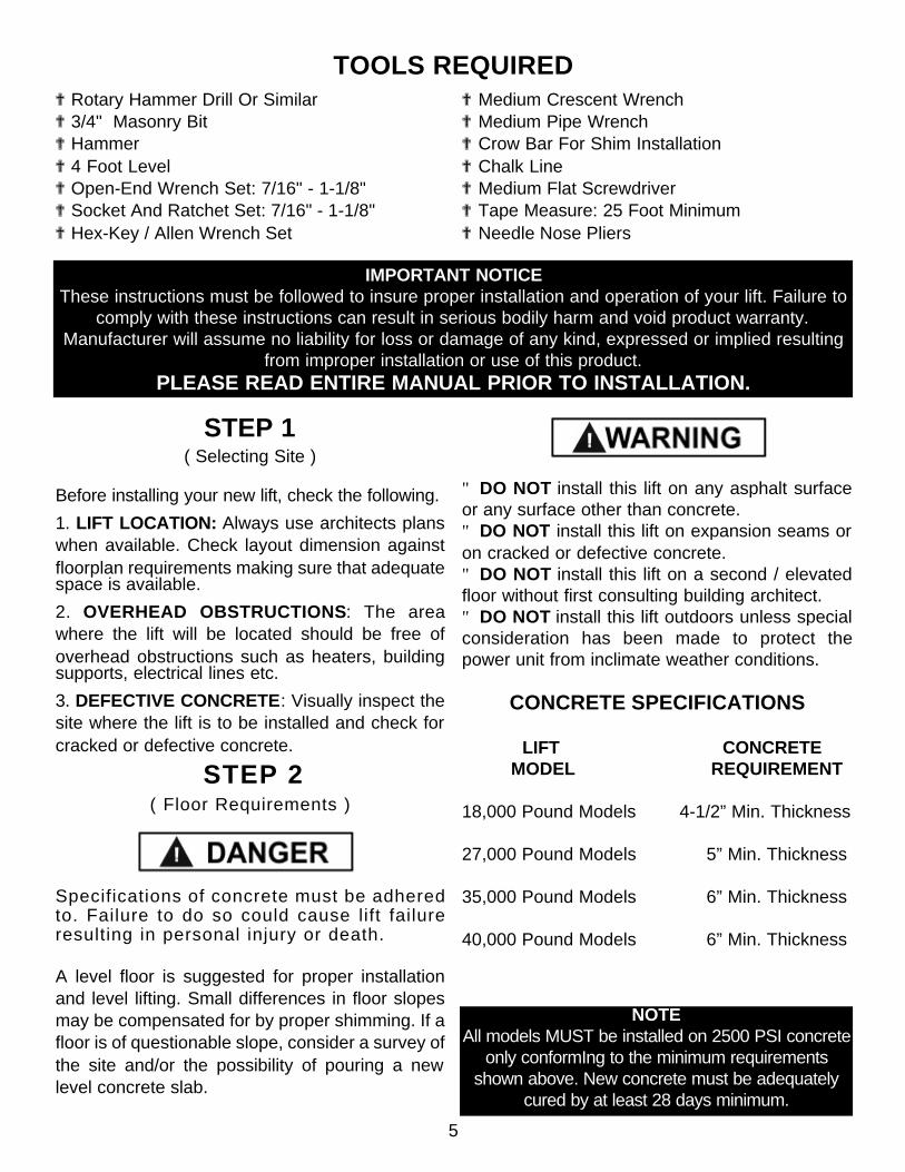
STEP 1( Selecting Site )
Before installing your new lift, check the following.
1. LIFT LOCATION: Always use architects planswhen available. Check layout dimension againstfloorplan requirements making sure that adequatespace is available.
2. OVERHEAD OBSTRUCTIONS: The areawhere the lift will be located should be free ofoverhead obstructions such as heaters, buildingsupports, electrical lines etc.
3. DEFECTIVE CONCRETE: Visually inspect thesite where the lift is to be installed and check forcracked or defective concrete.
STEP 2( Floor Requirements )
Specifications of concrete must be adheredto. Failure to do so could cause lift failureresulting in personal injury or death.
A level floor is suggested for proper installationand level lifting. Small differences in floor slopesmay be compensated for by proper shimming. If afloor is of questionable slope, consider a survey ofthe site and/or the possibility of pouring a newlevel concrete slab.
"DO NOT install this lift on any asphalt surfaceor any surface other than concrete."DO NOT install this lift on expansion seams oron cracked or defective concrete."DO NOT install this lift on a second / elevatedfloor without first consulting building architect."DO NOT install this lift outdoors unless specialconsideration has been made to protect thepower unit from inclimate weather conditions.
CONCRETE SPECIFICATIONS
LIFT CONCRETE MODEL REQUIREMENT
18,000 Pound Models 4-1/2” Min. Thickness
27,000 Pound Models 5” Min. Thickness
35,000 Pound Models 6” Min. Thickness
40,000 Pound Models 6” Min. Thickness
TOOLS REQUIRED? Rotary Hammer Drill Or Similar? 3/4" Masonry Bit? Hammer? 4 Foot Level? Open-End Wrench Set: 7/16" - 1-1/8"? Socket And Ratchet Set: 7/16" - 1-1/8"? Hex-Key / Allen Wrench Set
? Medium Crescent Wrench? Medium Pipe Wrench? Crow Bar For Shim Installation? Chalk Line? Medium Flat Screwdriver? Tape Measure: 25 Foot Minimum? Needle Nose Pliers
IMPORTANT NOTICEThese instructions must be followed to insure proper installation and operation of your lift. Failure to
comply with these instructions can result in serious bodily harm and void product warranty.Manufacturer will assume no liability for loss or damage of any kind, expressed or implied resulting
from improper installation or use of this product. PLEASE READ ENTIRE MANUAL PRIOR TO INSTALLATION.
NOTEAll models MUST be installed on 2500 PSI concrete
only conformIng to the minimum requirementsshown above. New concrete must be adequately
cured by at least 28 days minimum.
5

FLOORPLAN
A
B C
X
X
APPROACH
DIMENSIONSMODEL A B CFL-18 187” 123” 223”
BP-18 197” 144” 244”
BP-27 / BP-27A 257” 144” 294-1/2”
BP-27X / BP-27XA 317” 144” 348-1/4”
BP-35 / BP-35A 257” 144” 294-1/2”
BP-35X / BP-35XA 317” 144” 348-1/4”
BP-40 / BP-35A 257” 144” 294-1/2”
BP-40X / BP-35XA 317” 144” 348-1/4”
NOTEThe power unit can belocated in either “X”locations shown above.For right-side power unitlocation the power beammust be installed on theright side and for left-side power unit locationthe power beam must beinstalled on the left side.
P O W E R B E A M
STEP 3( Site Layout )
1. Determine which end of the lift will be the approachside. Remember, the drive-on ramps will overhangthis side of the lift by 30” ( 48” on FL-18 model. )
2. Now determine which side you prefer the powerunit to be located on. Remember, the POWER-BEAMmust be installed on the same side as the power unit.
ALIGNMENT MODELS - For these models, thePOWER BEAM and POWER UNIT must be installedon the DRIVER SIDE / LEFT SIDE only.
3. Once a location is determined, use a carpenterschalk line to layout a grid for the post locations.
Remember to keep all dimensions and squarenesswithin 1/8” or malfunctioning of the lift will occur.
4. After the post locations are properly marked, use achalk or crayon to make an outline of the posts on thefloor at each location using the post baseplates as atemplate.
5. Double check all dimensions and make sure thatthe diagonal measurements are equal from allcorners.
6. Before continuing with the installation it is helpful tostand the posts up at their respective locations andget a visual of the shop, aisles and other clearances.Also, this is a good time to drive a vehicle intoposition and check for adequate clearance.
6

2. Connect the end of each chain to theCYLINDER CHAIN CONNECTOR using fourof the 5/16” x 2” hardened dowel pins. ( SeeFig. 3 )
3. Once the chains are routed and connectedproperly, drop the ends of each chain throughthe openings at the bottom of the power beam.
STEP 4( Routing the chains through the CROSS-TUBES )
1. Before starting, prepare the two CROSS-TUBES by routing the two cross-tube chains through thecenter of each cross-tube. ( See Fig. 1 )
2. Pay careful attention making sure that the chains are not twisted. Once the chains are routedproperly, tape / tie the ends of each chain to the ends of the CROSS-TUBES to hold in positionduring the installation process.
STEP 5( Preparing the POWER-BEAM )
1. Before starting, prepare the POWER-BEAM by routing the four power-beam chains as shown below.Pay careful attention making sure that the chains are not twisted and are routed over the rollers at eachend. ( See Fig. 2 )
Fig. 1
Fig. 2
Fig. 3
7

STEP 6( Mounting the POWERSIDE columns. )
1. Locate the two POWERSIDE columns. ( The topof these columns will have square cutouts. )
2. One of the POWERSIDE columns will have apower-unit mounting plate attached. Position thiscolumn at the designated chalk location for the powerunit. Place the remaining POWERSIDE column at theother available POWERSIDE chalk location.
3. Before proceeding, double check measurementsand make certain that the bases of each column aresquare and aligned with the chalk line.
4. Using the baseplate on each POWERSIDEcolumn as a guide, drill each anchor hole in theconcrete approximately 4-1/2” deep using a rotaryhammer drill and 3/4” concrete drill-bit. To assure fullholding power, do not ream the hole or allow the drillto wobble. ( See Fig. 4 & 5 )
5. After drilling, remove dust thoroughly from eachhole using compressed air and/or wire brush. Makecertain that the column remains aligned with thechalk line during this process.
6. Assemble the washers and nuts on the anchorsthen tap into each hole with a hammer until thewasher rests against the baseplate. Be sure that ifshimming is required that enough threads are leftexposed. ( See Fig. 6 )
NOTE:DO NOT tighten the anchor bolts until the
POWER-BEAM is positioned and bolted firmly tothe top of the powerside columns.
ASSEMBLY DRAWING
Fig. 4
Fig. 5
Fig. 6
8

7. If shimming is required, insert the shims asnecessary under the baseplate so that when theanchor bolts are tightened, the columns will beplumb. ( See Fig. 7 )
STEP 7( Mounting the POWER-BEAM. )
1. Once the POWERSIDE columns are secure,mount the power beam to the top of the POWER-SIDE columns using the 1/2"-13 x 2" Bolts andnuts then drop the chains through the openings.( See Fig. 8 & 9 )
NOTE:Make sure that the tail end of the cylinder where
the hydraulic ports are located is located closest tothe POWER UNIT. ( See ASSEMBLY DRAWING )
STEP 8( Mounting the OFFSIDE columns. )
1. Position the OFFSIDE columns at the designatedchalk locations and secure to the floor following thesame procedures as outlined in STEP FIVE.
STEP 9( Positioning the CROSS-TUBES. )
1. After the columns and POWERBEAM have been installed, position the CROSS-TUBES on thebottom safety lock position making sure the POWERSIDE ramp position blocks and Safety Cylinderbrackets are positioned correctly. ( See Fig. 10 )
Fig. 7
Fig. 8
Fig. 9
Fig. 109

STEP 10( Connecting The POWERSIDE Chains )
1. It is necessary to extend the TOP CYLINDERprior to connecting the POWERSIDE chains. To dothis, first remove the plastic shipping plugs from theend of the cylinder. With the shipping plugsremoved, extend the cylinder using a cable puller orair gun.
If using air pressure to extend the cylinder, DONOT EXCEED 75 P.S.I. Be very cautious as
cylinder may jump erratically.
2. After the cylinder has been extended, connect thefour POWERSIDE chains to the CROSS-TUBEchain connectors using the 5/16” hardened dowelpins. ( See Fig. 12 & 13 )
STEP 11( Connecting The CROSS-TUBE Chains )
Connect the two CROSS-TUBE chains to the chainconnectors located at the BOTTOM OF EACHPOWERSIDE column using the master linkssupplied. Next route the CROSS-TUBE chainsthrough the top of the OFFSIDE columns makingsure that the threaded end extends at least 1/4”beyond the end of the nylock nut. (See Fig. 14 & 15)
PAY CAREFUL ATTENTION WHEN CON-NECTING CHAINS. Make sure that the con-necting pins pass through all leafs in the chain andthrough all sections of the chain connectors. YOU
MUST install center and outside leafs of chain whenconnecting CROSS-TUBE chains to POWER-SIDE columns. Failure to do so could cause lift fail-
ure resulting in personal injury or death.
USE ONLY FACTORY SUPPLIEDCONNECTING PINS AND/OR CHAIN
CONNECTING LINKS.
Fig. 12
Fig. 13
Fig. 14
Fig. 15
10

STEP 12( Preparing The POWERSIDE Runway )
1. First locate the POWERSIDE runway. ThePOWERSIDE runway will have a hole on one endwhere the BULKHEAD FITTING for the air safetysystem will be installed. ( See Fig. 16 )
2. Install the BULKHEAD fitting and secure. Nowinstall the MALE BRANCH TEE inside the runwayand connect the airline until it exits at each end ofthe runway. Make sure that the airline is connectedproperly and the threaded connectors are tight.
STEP 13( Positioning The Runways )
1. After the bulkhead fitting and airline is installedposition the POWERSIDE runway within the ramplocating blocks at the top of each CROSS-TUBE.Make sure the airline is not pinched or damagedwhen positioning the POWERSIDE runway. Next,position the OFFSIDE runway adjacent thePOWERSIDE runway. ( See Fig. 17 )
STEP 14( Installing The Air Safety System )
1. Install the air safety cylinders as shown below.The air fitting for each cylinder MUST be positionedon the top. It is recommended to lubricate eachcylinder with spray lubricant such as WD-40 orsimilar. ( See Fig 18 )
2. Install the airline as shown on the following page.It may be necessary to elevate the POWERSIDErunway to gain access to the airline at each end ofthe runway. Make sure that the tubing is clear of allpinch points and the fittings are tightened securely.
3. Install the power unit, push-button air valve andcoiled air hose as shown below.
Fig. 16
Fig. 17
Fig. 18
11

12

STEP 15( Hydraulic Hose Connections )
1. Connect the two 90 degree hydraulic fittings andflow-control valve to the main cylinder.( See Fig. 19 )
2. Install the two 90 degree hydraulic fittings to thePOWER PORT and RETURN PORT of the powerunit and connect the hoses as described below. Itwill be necessary to remove shipping plugs fromboth ports prior to installing fittings. After the hosesare connected, fill the power unit with 18 QTS. 10WT. HYDRAULIC FLUID OR DEXRON II ATF.
STEP 16( Electrical Connections )
NOTE:Have a certified electrician run 208 - 230 volt
single phase 60 HZ power supply to motor. ( If youordered optional three phase power refer to thedata plate found on the motor for proper power
supply. ) Be sure to size wire for a 25 amp circuit.
RISK OF EXPLOSION!This equipment has internal arcing or parts that
may spark and should not be exposed toflammable vapors. Motor should not be located in
a recessed area or below floor level. NEVERexpose motor to rain or other damp environments.DAMAGE TO MOTOR CAUSED BY WATER IS
NOT COVERED UNDER WARRANTY.
STEP 17( Power Unit Start-Up )
1. Test power unit by depressing button. If motorsounds like it is operating properly, raise lift to fullheight and check all hose connections for leaks. IFMOTOR GETS HOT OR SOUNDS PECULIAR,STOP IMMEDIATELY AND RE-CHECK ELEC-TRICAL CONNECTIONS.
STEP 18( Installing Front Tire Stops )
IMPORTANT NOTE:DO NOT USE 110 VOLT POWER SUPPLY FORTHIS POWER UNIT. DAMAGE TO MOTOR WILL
OCCUR WHICH IS NOT COVERED UNDERWARRANTY. You must use a separate circuit
breaker for each lift.
Fig. 19
13

STEP 19( Installing Front Drive-Up Ramps )
STEP 20( Final Adjustments )
1. Load the lift with a vehicle such as light-dutytruck or van.
2. Raise the lift until the safety lock on the POWERUNIT column comes within 1/4” of the first safetylock ladder.
3. Tighten / loosen the adjusting nut on top of theOFFSIDE column directly across from the POWERUNIT column until the safety lock for that columncomes within 1/4” of the safety lock ladder.
4. Repeat this step for the remaining columns untilall safeties comes within 1/4” of the safety lockladders. NOTE: Adjustments for the POWERSIDEchains should be made by using the extra chainconnecting links supplied with your lift.
STEP 21( Leveling Alignment Runways )
1. Using a level or transit, adjust the runways so thatthey are level in all directions while resting on theBOTTOM safety lock. Adjustment bolts are locatedat the bottom of each column. ( See Fig. 20 )
STEP 22( Installing The Optional Ramp Extensions )
Fig. 20
14

15

16

17

18
19

20

21

22

23

24
