installation and operating manual series kn, knp ball …
TRANSCRIPT

INSTALLATION AND OPERATING MANUAL
SERIES KN, KNP
Ke
Thstrtraco
Repeth©
Ball Valve
ep for future use!
is operating manual must beictly observed beforensport, installation,mmissioning etc.
production is generallyrmitted with indication ofe source. ITT Richter Chemie-Technik.
9520
-050
-en
Re
visi
on 0
0 E
diti
on 0
1/20
03
with ball/stem unitand Richter ENVIPACK
universal packing

9520-050-en Revision 00TM 5351 MPE/Se/Wm Seite 2 Edition 01/2003
List of Centents
1 Technical data .....................................31.1 Intended use ............................................31.2 Name plate, CE and body markings ........41.3 Tightening torques ...................................41.4 Breakaway torques ..................................41.5 Flow rates.................................................51.6 Pressure-temperature-diagram................5
2 Notes on safety ...................................52.1 For customer / operator ...........................52.2 Inadmissible modes of operation ...........5
3 Transport and storage........................63.1 Storage.....................................................63.2 Return consignments ...............................6
4 Installation ...........................................64.1 Flange caps and gaskets .........................64.2 Direction of flow and installation position .64.3 Grounding ................................................64.4 Test pressure ...........................................6
5 Operation.............................................75.1 Initial commissioning ............................... 75.2 Inadmissible modes of operation and their
consequences ......................................... 75.3 Shutdown................................................. 7
6 Malfunctions........................................7
7 Maintenance........................................87.1 Dismantling.............................................. 8
7.1.1 KN with lever 87.1.2 Packing bellows 87.1.3 KNP with actuator 8
7.2 Assembly ................................................. 87.2.1 Packing bellows 87.2.2 KN with lever 87.2.3 KNP with actuator 8
7.3 Conversion from lever to actuator ........... 8
8 Drawings .............................................98.1 Sectional drawing KN with handwheel..... 98.2 Sectional drawing KNP with actuator..... 10
Relevant documents
♦ Declaration of conformity acc. to the EC PressureEquipment Directive 97/23/EG
♦ Form for General Safety CertificateQM 0912-16-2002
♦ For KNP: Operating manual for actuator♦ Depending on option, relevant drawing: Double packing 9520-00-0002 Ball/stem unit extension 9520-00-0003 Lever extension 9520-00-0004 Limit switch IFM 9520-00-0006 Limit switch VDE/VDI 9520-00-0008 Locking plate 9520-00-0009

Installation and Operating ManualSeries KN, KNP
9520-050-en Revision 00TM 5351 MPE/Se/Wm Seite 3 Edition 01/2003
1 Technical dataManufacturer: ITT Richter Chemie-Technik GmbH Otto-Schott-Str. 2 D-47906 Kempen Tel. : +49 (0) 2152 146-0 Fax: +49 (0) 2152 146-190E-mail : [email protected]: www.itt-richter.de Designation : Ball valve with ball/stem unit and Richter ENVIPACKuniversal packing, two-piece body. Tightness tested to DIN 3230, Part 3 Series KN � Design with lever or hand gear KNP� Design prepared for pneum., hydr.
or elec. actuator to DIN/ISO 5211 Face to face : DIN EN558-1 basic series 1, ISO 5752 series 1 Flange connecting dimensions: DIN EN 1092-2, design B (ISO 7005-2 type B) PN 16. General conditions of delivery for valves to DIN 3230.
Materials : Body material: Ductile cast iron EN-JS 1049 to DINEN 1563 (0.7043 DIN 1693) Lining material: PFA or FEP on request : conductive design
Temperature range : See pressure-temperature diagram in Section 1.6.
Operating pressure: 15 – DN 150 from vacuum to 16 bar DN 200 max. 10 bar optional : DN 25 – DN 80 to max. 25 bar
Ball valve sizes in mm : DN 15, 20, 25, 40, 50, 80, 100, 150, 200
Weight, KN hand-activated:Nom.size 15 20 25 40 50 80 100 150 200
kg 5.5 6 6 14 16 35 55 105 120 For weight of actuator, see actuator manufacturer'smanual. Installation position: Arbitrary, with low-cavity ball/stem units a directionarrow indicates the direction of flow. See Sections 4.2 and 8.2.
Dimensions and individual parts:See sectional drawings in Section 8
Wear parts: Seat rings Packing components Ball/stem unit Options : Richter ENVIPACK double packing for particularly high safety requirements, self-adjusting. On request, monitoring and rinsing connection. Ball/stem unit extension for isolated pipes. Hand lever extension depending on requirements. Limit switches for remote monitoring of hand and remote-activatedball valves. Lockable hand lever to prevent unauthorised operation. Stainless steel heating jacket can be retrofitted, suitable for all common heatcarriers. 1.1 Intended use Ball valves are open/closed valves. Richter ball valves of the series KN/KNP are pressurecontaining components in accordance with thePressure Equipment Directive (PED) for the passageand shut-off of fluids. The valves are suitable forvapours, gases and non-boiling liquids of group 1according to the PED and have a corrosion-resistantplastic lining. Solids can lead to increased wear, damage to sealingsurfaces or to a reduction in the service life of thevalve. The operator must carefully examine in the event ofoperating data other than those provided whether thedesigns of the valve, accessories and materials aresuitable for the new application (consult the manu-facturer).

Installation and Operating ManualSeries KN, KNP
9520-050-en Revision 00TM 5351 MPE/Se/Wm Seite 4 Edition 01/2003
1.2 Name plate, CE and bodymarkings
The stainless steel name plate is firmly riveted to thebody.
Another stainless steel tag plate riveted to the valveindicates the test pressure. If the operator attaches his identification, it must beensured that the valve matches the application inquestion. Example of name plate with CE marking:
No CE marking is required for the sizes 15, 20 and25; the name plate therefore has no CE marking. Body identification : The following are visible on the body according to DINEN 19 and AD 2000 A4:♦ Nominal size♦ Rated pressure♦ Body material♦ Manufacturer's identification♦ Melt number/Foundry identification♦ Foundry date
1.3 Tightening torques Tighten all screws in diametrically oppositesequence! The tightening torques for pipe screws and bodyscrews mentioned must not be exceeded. For anexception, see Section 6, Flange connection ballvalve/pipe is leaking. Packing screws The pretension has been reached when the springgland follower is bent horizontally.
Pipe screws greasedThe following tightening torques are recommendedfor the pipe screws:
Flangesnom. size
(mm)Screws
Tighteningtorque(Nm)
15 4 x M12 1220 4 x M12 1225 4 x M12 1240 4 x M16 2250 4 x M16 3080 8 x M16 25100 8 x M16 30150 8 x M20 55200 8 x M24 75
Body screws greased
Nom. size(mm)
ScrewsTightening
torque (Nm)
15 4 x M12 3520 4 x M12 3525 4 x M12 3540 4 x M16 4550 4 x M16 4580 8 x M16 50100 8 x M16 80150 8 x M20 150200 8 x M24 100
1.4 Breakaway torques Test medium: water 20 °C Higher breakaway torques may occur with othermedia.
DN ∆p in bar3 6 10 16 max. adm.
mm Nm Nm Nm Nm Nm
15 8 8 8 10 7020 8 8 8 10 7025 12 12 12 12 7040 20 20 20 25 22550 25 25 25 30 22580 60 60 65 80 500
100 80 80 90 170 500150 200 250 350 ./. 2200200 200 250 350 ./. 2200
Installation and Operating ManualSeries KN, KNP
9520-050-en Revision 00TM 5351 MPE/Se/Wm Seite 5 Edition 01/2003
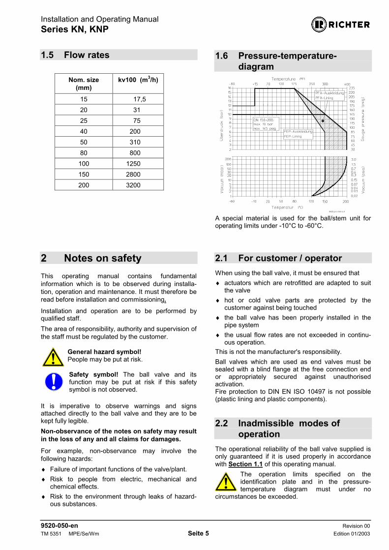
1.5 Flow rates
Nom. size(mm)
kv100 (m3/h)
15 17,520 3125 7540 20050 31080 800100 1250150 2800200 3200
1.6 Pressure-temperature-
diagram
A special material is used for the ball/stem unit foroperating limits under -10°C to -60°C.
2 Notes on safetyThis operating manual contains fundamentalinformation which is to be observed during installa-tion, operation and maintenance. It must therefore beread before installation and commissioning. Installation and operation are to be performed byqualified staff.The area of responsibility, authority and supervision ofthe staff must be regulated by the customer.
General hazard symbol! People may be put at risk. Safety symbol! The ball valve and itsfunction may be put at risk if this safetysymbol is not observed.
It is imperative to observe warnings and signsattached directly to the ball valve and they are to bekept fully legible.Non-observance of the notes on safety may resultin the loss of any and all claims for damages.
For example, non-observance may involve thefollowing hazards:♦ Failure of important functions of the valve/plant.♦ Risk to people from electric, mechanical and
chemical effects.♦ Risk to the environment through leaks of hazard-
ous substances.
2.1 For customer / operator When using the ball valve, it must be ensured that♦ actuators which are retrofitted are adapted to suit
the valve♦ hot or cold valve parts are protected by the
customer against being touched♦ the ball valve has been properly installed in the
pipe system♦ the usual flow rates are not exceeded in continu-
ous operation. This is not the manufacturer's responsibility. Ball valves which are used as end valves must besealed with a blind flange at the free connection endor appropriately secured against unauthorisedactivation. Fire protection to DIN EN ISO 10497 is not possible(plastic lining and plastic components). 2.2 Inadmissible modes of
operation The operational reliability of the ball valve supplied isonly guaranteed if it is used properly in accordancewith Section 1.1 of this operating manual.
The operation limits specified on theidentification plate and in the pressure-temperature diagram must under no
circumstances be exceeded.

Installation and Operating ManualSeries KN, KNP
9520-050-en Revision 00TM 5351 MPE/Se/Wm Seite 6 Edition 01/2003
3 Transport and storage It is imperative, for all transport work, toobserve generally accepted engineeringpractice and the accident prevention
regulations. The ball valve is supplied with flange caps.Do not remove them until just beforeinstallation. They protect the plastic surfaces
against dirt and mechanical damage. Handle the goods being transported with care. Duringtransport the valve must be protected against impactsand collisions. Directly after receipt of the goods, the consignmentmust be checked for completeness and any in-transitdamage. Do not damage paint protection.
3.1 Storage If the valve is not installed immediately after delivery,it must be put into proper storage. It should be stored in a dry, vibration-free and well-ventilated room at as constant a temperature aspossible.
3.2 Return consignments Valves which have conveyed aggressive ortoxic media must be well rinsed and cleanedbefore being returned to the manufacturer's
works. A General Safety Certificate on the field ofapplication is to be enclosed with the returned goods. Pre-printed forms are enclosed with the installationand operating manual. Safety precautions and decontamination measuresare to be mentioned.
4 Installation Examine valve for in-transit damage, damaged ballvalves must not be installed. Before installation the valve and the connecting pipemust be carefully cleaned to remove any dirt,especially hard foreign matter. 4.1 Flange caps and gaskets Leave protective caps on the flanges until just prior toinstallation. Where there is a particularly high risk of damage tothe plastic sealing surfaces, e.g. if the mating flangesare made of metal or enamel, PTFE-lined gasketswith a metal inlay should be used. These gaskets areavailable as special accessories in the ITT Richterrange.
4.2 Direction of flow and installa-tion position
Installation is independent of the direction of flow. Any installation position can be chosen. Otherwise, it is marked by a direction arrow on theball valve, e.g. in the case of cavity-free ball/stemunits. 4.3 Grounding Grounding is achieved via the pipe screws. The ball/stem unit is grounded using a groundingspring washer 557. 4.4 Test pressure The test pressure PT of an open valve must notexceed the value of 1.5 x PN/PS as per the identifica-tion of the valve.

Installation and Operating ManualSeries KN, KNP
9520-050-en Revision 00TM 5351 MPE/Se/Wm Seite 7 Edition 01/2003
5 Operation
5.1 Initial commissioning Normally, the ball valves have been testedfor leaks with air or water. Unless otherwise agreed, there could be
residual amounts of water in the flow section of theball valve; this could result in a possible reaction withthe medium. Following the initial loading of the ball valve withoperating pressure and temperature, the torques ofall connecting bolts must be checked. See Section 1.3. 5.2 Inadmissible modes of opera-
tion and their consequences♦ The ball valve is an open/closed valve and is not
to be operated in an intermediate position.Damage to the seat rings or the ball/stem unitcould occur.
♦ Crystallisation may result in damage to the seatrings or ball/stem unit. This can be prevented byheating.
♦ In extreme cases this may cause blocking.♦ Operation with solids leads to increased wear.♦ Operating during cavitation leads to increased
wear.♦ Non-observance of the pressure-temperature
diagram can lead to damage.♦ Do not subject the handwheel to heavy loads;
the handwheel or ball valve may be damaged.♦ Do not use a lever extension as otherwise there
is a risk of damage. 5.3 Shutdown The local regulations are to be observed whendismantling the ball valve. Prior to starting any repair work, the ball valve is tobe thoroughly cleaned. Even if the valve has beenproperly emptied and rinsed, residual medium maystill be found in the valve, e.g. between the lining andthe body.
6 Malfunctions♦ Flange connection ball valve/pipe is leaking
Retighten the flange screws to a tightening torqueaccording to Section 1.3. If this does not remedythe leak, the recommended torques may be ex-ceeded by 10%. If this also fails to stop the leak, dismantle andinspect the ball valve.
♦ Flange connection main body/body end piece isleaking Retighten body screws. See paragraph "Flangeconnection ball valve/pipe is leaking".
♦ Packing is leaking Retighten packing nuts according to the details inSection 1.3.
♦ Ball valve does not operate Is the actuator being supplied with power? Is any directional control valve connected cor-rectly? Is there any foreign matter in the ball valve?
♦ The ball no longer closes completely Is the stem deformed? Is the coupling worn? With a worm gear or actuator, check whether theend stops can be re-adjusted. The operatingmanuals of the gear and actuator manufacturerscontain accurate instructions.
Never apply force to the lever or use anextension.
1. Try to get the ball valve working again by
moving the lever to and fro.2. Remove the lever stop and try to switch against
the normal direction of rotation.3. If activation is not possible with the max. ad-
missible breakaway torque as per Section 1.4,dismantle ball valve and inspect individualcomponents.

Installation and Operating ManualSeries KN, KNP
9520-050-en Revision 00TM 5351 MPE/Se/Wm Seite 8 Edition 01/2003
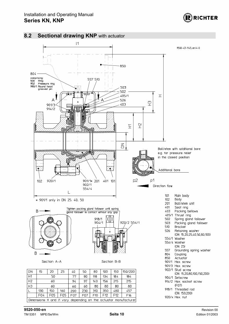
7 Maintenance Spare parts are to be ordered with all the details inacc. with the valve identification. Only original spare parts may be installed. 7.1 Dismantling7.1.1 KN with lever
� Remove lever 203.� Take out grounding spring washer 557.� Dismantle packing gland follower 503 and spring
gland follower 502.� The thrust ring 405/1, packing bellows 403 and
retaining washer 526 (not in DN 150 and DN200) are one unit and it is levered out using 2screwdrivers.
� Undo screw connection body end piece/mainbody.
� Remove body end piece 102.� When dismantling the ball/stem unit 201, make
sure that the body lining is not damaged.� Remove seat rings 401. 7.1.2 Packing bellows� Remove retaining washer 526.� Separate thrust ring 405/1 and packing bellows
403 by pushing them apart. 7.1.3 KNP with actuator
� Remove actuator 850 and coupling 804.� Dismantle packing gland follower 503 and spring
gland follower 502.� Remove bracket 510. Further dismantling is performed as described inSection 7.1.1.
7.2 Assembly� Prior to assembly all parts are to be cleaned and
the plastic-lined components checked for dam-age.
� Insert seat rings 401 in the main body 101 andbody end piece 102.
� When installing the ball/stem unit 201, makesure that the lining of the main body is not dam-aged. An additional bore in the ball/stem unit,e.g. to ensure it is cavity-free, must lie on the p1side in the closed position.
� Mount body end piece 102. Tighten the bodyscrews to a tightening torque according to Sec-tion 1.3 in diametrically opposite sequence.
7.2.1 Packing bellows� Press thrust ring 405/1 into packing bellows 403.� Install retaining washer 526 (not in DN 150 and
DN 200).� Press unit into body end piece 102.� Press in grounding spring washer 557.
7.2.2 KN with lever
� Mount lever stop, spring gland follower andpacking gland follower. Observe tighteningtorques as per Section 1.3. Seal any tappedbores still open with plugs.
� Mount lever.
7.2.3 KNP with actuator
� Mount spring gland follower and packing glandfollower. Observe tightening torques as perSection 1.3.
� Mount bracket with the opening at right angles tothe direction of flow.
� Mount coupling and actuator. Observe theactuator position in accordance with the actuatoroperating manual.
7.3 Conversion from lever toactuator
� Select the actuator in accordance with theinstructions of the actuator manufacturer.
� Remove hand lever.� Remove lever stop and plug.� Check the fits of the coupling, bracket and
actuator.� Mount bracket with the opening at right angles to
the direction of flow.� Mount coupling and actuator. Observe the
actuator position in accordance with the actuatoroperating manual.

Installation and Operating ManualSeries KN, KNP
9520-050-en Revision 00TM 5351 MPE/Se/Wm Seite 9 Edition 01/2003
8 Drawings
8.1 Sectional drawing KN with handwheel
Installation and Operating ManualSeries KN, KNP
9520-050-en Revision 00TM 5351 MPE/Se/Wm Seite 10 Edition 01/2003
8.2 Sectional drawing KNP with actuator

Compiled: BPM/Lam dated: 10.02.03 Page: 1 QM No.: 0912-16-2002/4-01Approved: BPM/Lam dated: 10.02.03 of : 1
Return to: ITT Richter Chemie-Technik GmbHBKSFax No.: 02152/146-190
G E N E R A L S A F E T Y C E R T I F I C A T E
for order No.:
ITT Richter serial No.:
We herewith declare that the equipment mentioned below is being returned for inspection/repair.
Type:
No.:
Reason for inspection/repair:
The equipment was used for the following fluids (Details according to safety data sheet asper 91/155/EEC):Always indicate the last product conveyed.
The equipment was carefully emptied and cleaned both inside and outside prior todispatch/return:
yes no
The following safety precautions as regards rinsing fluids, residual fluids and wastedisposal are required (indicate decontamination agent):
We herewith declare that the above. information is correct and complete and that transport will be madeaccording to the statutory provisions.
Company: Phone:
Fax:
E-mail address:
Address:
Name: Position:(in capitals)
Date Stamp/Signature

Safety notes for applications in potentially explosive areas based on the
Directive 94/9/ EC (Atex 95)
9500-001-en 1 02.04.2004 Rev. 03
The valves are intended for use in a potentially explosive area and are therefore subject to the con-formity assessment procedure of the directive 94/9/EC (ATEX). As part of this conformity assessment, an ignition hazard analysis to EN 13463-1 to satisfy the funda-mental safety and health requirements was conducted with the following result: - The valves do not have any ignition source of their own and can be operated both manu-
ally as well as mechanically/electrically. - The valves are not covered by the scope of application of the ATEX directive and therefore
do not need to be identified accordingly. - The valves may be used in a potentially explosive area. Supplementary notes:
- Electric/mechanical actuators must be subjected to their own conformity assessment to ATEX.
It is imperative to observe the individual points of intended use for application in a potentially explosive area.
1. Intended use: Inadmissible modes of operation, even for brief periods, may result in serious damage to the unit. In connection with explosion protection, potential sources of ignition (overheating, electro-static and induced charges, mechanical and electric sparks) may result from these inadmissi-ble modes of operation; their occurrence can only be prevented by adhering to the intended use. Furthermore, reference is made in this connection to the Directive 95/C332/06 (ATEX 118a) which contains the minimum regulations for improving the occupational health and safety of the workers who may be at risk from an explosive atmosphere.
� A difference is made between two cases for the use of chargeable liquids (conductivity < 10-8 S/m):
1. Chargeable liquid and non-conductive lining Charges can occur on the lining surface. As long as the valve is completely filled with medium, no hazardous discharges can result from these charges. As a result, this can produce discharges inside the valve. However, these discharges cannot cause ignitions if the valve is completely filled with medium. If the valve is not completely filled with medium, e.g. during evacuation and filling, the forma-tion of an explosive atmosphere must be prevented, e.g. by superimposing a layer of nitrogen. It is recommended to wait 1 hour before removing the valve from the plant in order to permit the elimination of static peak charges. This means that, to safely prevent ignitions, the valve must be completely filled with medium at all times or else a potentially explosive atmosphere must be excluded by superimposing a layer of inert gas.
2. Chargeable liquid and conductive lining No hazardous charges can occur as charges are discharged direct via the lining and shell (surface resistance < 109 Ohm, leakage resistance < 106 Ohm) The following special feature applies to the series with bellows (HV, RSS, BAV, KSE, GU, GUT, PA): The bellows are not offered with a conductive lining, i.e. the restrictions under point 1 apply.

Safety notes for applications in potentially explosive areas based on the
Directive 94/9/ EC (Atex 95)
9500-001-en 2 02.04.2004 Rev. 03
Static discharges of non-conductive linings are only produced through the interaction with a non-conductive medium and are therefore the responsibility of the plant operator. Static discharges are not sources of ignition which stem from the valves themselves!
� The temperature of the medium must not exceed the temperature of the corresponding tempera-ture class or the maximum admissible medium temperature as per the operating manual.
� If the valve is heated (e.g. heating jacket), it must be ensured that the temperature classes pre-scribed in the Annex are observed.
� To achieve safe and reliable operation, it must be ensured in inspections at regular intervals that the unit is properly serviced and kept in technically perfect order. Increased wear to the valve can be expected with the conveyance of liquids containing abrasive constituents. The inspection intervals are to be reduced compared with the usual times.
� Actuators and electric peripherals, such as temperature, pressure and flow sensors etc., must comply with the valid safety requirements and explosion protection provisions.
� The valve must be grounded. This can be achieved in the simplest way via the pipe screws using tooth lock washers. Otherwise grounding must be ensured by other action, e.g. cable bridges.
� Attachments such as actuators, position controllers, limit switches etc. must satisfy the relevant safety regulations as regards explosion protection and, if required, be designed in compliance with Atex. Special attention must be paid to the appropriate safety and explosion protection notes in the re-spective operating manuals.
� Plastic-lined valves must not be operated with carbon disulphide.