installation and operating instructions - australia · smoke detectors be ... if the heater...
TRANSCRIPT

MODEL: TN 20
TN 20
IMPORTANT:KEEP THESE INSTRUCTIONS FOR FUTURE REFERENCE.
INSTALLATION AND OPERATING INSTRUCTIONS - AUSTRALIA
SAFETY NOTICEIf this stove is not properly installed, a house fire may result. For your safety,
follow the installation instructions. Contact local building or fire officials about restrictions and installation inspection requirements in your area.
SERIAL #
040217-20 TN20 AUSTRALIA 5055.552AS
AU
STR
ALI
A

NOTE: WE STRONGLY RECOMMEND THAT SMOKE DETECTORS BE INSTALLED.
If smoke detectors have been previ-ously installed, you may notice that they are operating more frequently. This may be due to curing of stove paint or fumes caused by accidentally leaving the fire door open. Do not disconnect the detectors. If neces-sary, relocate them to reduce their sensitivity.
SAFETY NOTICE:If this stove is not properly installed, a house fire may result. For your safety, follow the installation instructions. Contact local building or fire officials about res t r ic t ions and installation inspection requirements in your area.
Please read this entire manual before you install and use your new room heater. Failure to follow instructions may result in property damage, bodily injury, or even death.
Contents .......................................................................................................................... 2Safety and Maintenance ........................................................................................... 3Maintenance Checks .................................................................................................. 4
Formation and Need for Removal .......................................................... 5Chimney Fires ................................................................................................. 5Avoiding a Chimney Fire ............................................................................ 5
Creosote .......................................................................................................................... 5Appliance Dimensions ................................................................................................ 6Assembly .......................................................................................................................... 6
If You Suspect a Chimney Fire ................................................................. 6In Case of a Chimney Fire ......................................................................... 6
Clearances - Residential ........................................................................................... 7Floor Protector .............................................................................................................. 7Installation ..................................................................................................................... 8
Chimney and Connector ............................................................................ 9Installation Procedure -Residential ....................................................... 9
Firebrick Installation .................................................................................................10Pedestal Model ..............................................................................................11Leg Model .........................................................................................................11
Combustion Air .............................................................................................................11Wood Selection .............................................................................................12
Operation .......................................................................................................................12How to Test Your Wood .............................................................................13Lighting for the First Time ........................................................................13Lighting a Fire ................................................................................................13Normal Operation .......................................................................................13Proper Draft ...................................................................................................14Ash Removal ...................................................................................................14Disposal of Ashes .........................................................................................14Removal ............................................................................................................15Installation .......................................................................................................15
Baffle Tube Removal ..................................................................................................15Troubleshooting ...........................................................................................................17Replacement Parts - TN 20 ....................................................................................18Compliance Plate .......................................................................................................19
2 5055.552AS_040217-20TN 20
Contents

HOT GLASS WILL CAUSE BURNS.
DO NOT TOUCH GLASS UNTIL COOLED.
NEVER ALLOW CHILDREN TO TOUCH GLASS.
! DANGER
3 5055.552AS_040217-20 TN 20
Safety and Maintenance1. Burn cord wood only, dry well seasoned wood. The denser or heavier the wood
when dry, the greater its heat value. This is why hardwoods are generally preferred. Green or wet wood should not be used, as it will reduce heat output, as well as contributing significantly to creosote buildup.
2. Remove ashes frequently and only when the stove is cold. Too much ash could cause embers to roll out the door when it is opened. This may pose a fire hazard. For proper operation, maintain a 25 mm minimum ash base.
3. If glass becomes darkened from slow burning or poor wood, it can readily be cleaned with fireplace glass cleaner when stove is cold. Never scrape with an object or use abrasive cleaners that might scratch the glass. The type and amount of deposit on the glass is a good indication of the flue pipe and chimney buildup. A light brown dusty deposit that is easily wiped off usually indicates good combustion and dry, well-seasoned wood, therefore relatively clean pipes and chimney. On the other hand, a black greasy deposit that is difficult to remove is a result of wet and green wood and too slow a burning rate. This will also create heavy deposit buildup in the chimney.
4. DOOR GASKETS - The gasket used on this unit (16 mm medium density fiberglass rope) requires only light pressure to seal. This will prolong seal life. It is important that the door seal be maintained in good condition. Periodically inspect seals and replace if necessary. Follow instructions included in the door gasket kit (TN19.DGKIT ) obtainable from your nearest True North dealer.
5. DOOR GLASS - Do not slam loading door or otherwise impact glass. When closing door, make sure that no logs protrude to impact the glass. If the glass gets cracked or broken, it must be replaced before using the stove. Replacement glass can be obtained from your dealer. Use ceramic glass only. Do not substitute with any other type.
GLASS SIZE – 337mm x 235mm x 5mm thick. To remove broken glass, undo the four retaining screws and remove the clamps, noting position for re-assembly. Remove all pieces of glass. Be careful as they are very sharp. Install new glass complete with gasket. Replace clamps and screws.
6. Do not store wood within heater installation clearances, or within the space required for fuel loading and ash removal. Keep the area around the heater clean and free of loose combustibles, furniture, newspapers, etc.
7. If the heater requires cleaning, use mild soap and water only. Use of abrasive cleaners will void warranty.
8. Establish a routine for fuelling and firing the heater. Check daily for creosote buildup until experience shows how often you need to clean the chimney to be safe.
9. Be aware that the hotter the fire, the less creosote is deposited. Weekly cleaning may be necessary in mild weather, even though monthly cleaning is usually enough in the coldest months when burning rates are higher.
10. Instruct all members of your family on the safe operation of the heater. Ensure they have enough knowledge of the entire system if they are expected to operate it. Study the section on chimney fires and the importance of following the steps outlined "In Case of Chimney Fire".
WARNING: Never use chemicals or any other volatile liquid to start a fire. Do not burn garbage, or flammable fluids such as gasoline, naptha, or engine oil. We strongly recommend that smoke detectors be installed.
CAUTION: • Tighten screws very carefully, do not over-tighten• Do not clean glass when hot• Do not use abrasive cleaners on glass
WARNING: Only use materials supplied by manufacturer when doing maintenence or replacements.

4 5055.552AS_040217-20TN 20
Check the following parts for damage such as cracks, excessive corrosion, burned out sections and excessive warping**: (See website for descriptions and more detail)
Weekly:
- Firebrick - Visual, for cracking.- Door Gasket - sagging, placement, damage.
Monthly
• Brick rail tabs and brick rails.• Back side of airwash chamber.• Top Baffle Board.• Secondary Air (Baffle) Tubes• Boost tube cover.
When Cleaning the Chimney System:
• Top heat shield and mounting bolt.• Brick Rails.• Manifold.
.** Replace the Baffle tubes if they show signs of cracking or breakage.- Please contact your Dealer if you experience any of the damage listed above. Continuing to operate your stove with broken parts may accelerate damage to other parts and will void your warranty
Maintenance Checks

5 5055.552AS_040217-20 TN 20
CreosoteFormation and Need for Removal
When wood is burned slowly, it produces tar and other organic vapours, which combine with expelled moisture to form creosote. The creosote vapours condense in the relatively cool chimney flue of a slow burning fire. As a result, creosote residue accumulates on the flue lining. When ignited, this creosote makes an extremely hot fire.
The chimney connector and chimney should be inspected periodically (at least once every two months) during the heating season to determine if a creosote buildup has occurred. If creosote has accumulated (3 mm. or more), it should be removed to reduce the risk of a chimney fire.
1. Highest smoke densities occur when a large amount of wood is added to a bed of hot coals and the air inlet is closed. The heated wood generates smoke, but without ample air, the smoke cannot burn. Smoke-free, clean burning requires leaving the air inlet relatively wide open, especially during the first 10 to 30 minutes after each loading, when most of the smoke generating reactions are occurring. After 30 minutes or once the wood is fully charred, the air inlet can be turned down substantially without excessive smoke generation. Wood coals create very little creosote-producing smoke.
2. The cooler the surface over which the wood smoke is passing, the more creosote will be condensed. Wet or green wood contributes significantly to creosote formation as the excess moisture that is boiled off cools the fire, making it difficult for the tars and gases to ignite, thus creating dense smoke and poor combustion. This moisture-laden smoke cools the chimney, compounding the problem by offering the smoke the ideal place to condense.
In summary, a certain amount of creosote is inevitable and must be lived with. Regular inspection and cleaning is the solution. The use of dry, seasoned wood and ample combustion air will help to minimize the buildup.
Chimney Fires
Excessive creosote build-up can cause a chimney fire. Creosote comes from tar and organic vapours released from a slow burning wood fire. Flammable creosote will condense and accumulate in the lining of a relatively cool chimney. When ignited, this creosote can result in an extremely hot fire.
Avoiding a Chimney Fire
There are two ways to avoid chimney fires:
1. Keep your chimney clear of creosote build-up by cleaning your chimney before each burn season, and as necessary (accumulations of 3 mm or more) during the season.
2. Burn clean, well-seasoned wood only (seasoned at least one year). Avoid wet or green wood.
3. Do not burn household trash, cardboard, plastics, construction lumber, treated or beach wood (as these will corrode your fireplace and void your warranty).
4. Do not leave the air inlet wide-open for extended periods of time.
5. Keep a fire extinguisher handy.
6. Prepare a home evacuation plan with a place outside where everyone is to meet.
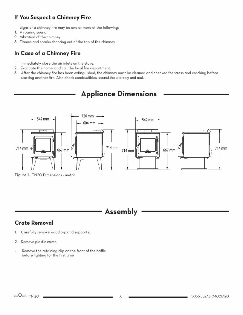
542 mm
667 mm
726 mm
714 mm
542 mm
714 mm714 mm 714 mm667 mm
604 mm
Figure 1. TN20 Dimensions - metric.
Appliance Dimensions
6 5055.552AS_040217-20TN 20
If You Suspect a Chimney Fire
Signs of a chimney fire may be one or more of the following:1. A roaring sound.2. Vibration of the chimney.3. Flames and sparks shooting out of the top of the chimney.
In Case of a Chimney Fire
1. Immediately close the air inlets on the stove.2. Evacuate the home, and call the local fire department.3. After the chimney fire has been extinguished, the chimney must be cleaned and checked for stress and cracking before starting another fire. Also check combustibles around the chimney and roof.
Crate Removal1. Carefully remove wood top and supports.
2. Remove plastic cover.
• Remove the retaining clip on the front of the baffle before lighting for the first time
Assembly

The stove may be installed on a combustible floor provided ember protection made from a 9mm thick non-combustible material (Bellis Board) with a thermal conductivity value of .1w/m2 degree K.
This protection must extend as follows:
300 mm on the firing side and be placed centrally to both sides of the door opening. See Figure #3.
Floor Protector
Minimum Width - 714 mm
Minimum Overall Depth - 1090mm
MinimumClearance to Combustibles
312mm 150mm
620mm
455mm
175mm
175mm
350mm
Figure 2. TN 20 AUS clearances.ai
Non-combustibleember protector
86 m
m
86 mm
300 mm
714 mm
1090 mm
Figure 3. TN 20 AUS Floor protector.ai
7 5055.552AS_040217-20 TN 20
Clearances - Residential
Clearances are based on testing done with a Wildcat Default Flue kit or equivelent.
MUST ONLY BE INSTALLED BY AN AUTHORISED PERSON IN COMPLIANCE WITH AS/NZS 2918
8 5055.552AS_040217-20TN 20
Installation Warning: Under no circumstances is this heater to be installed in a makeshift or "temporary" manner. It may be fired only after the stove is installed properly.
DO NOT ATTEMPT TO CONNECT THIS HEATER TO ANY AIR DISTRIBUTION DUCT.
Outside combustion air or fresh air into the room may be required in your area, consult local building codes (see Combustion Air section).
WARNING: THE APPLIANCE AND FLUE-SYSTEM SHALL BE INSTALLED IN ACCORDANCE WITH AS/NZS 2918 AND THE APPROPRIATE REQUIRMENTS OF THE RLEVANT BUILDING CODE OR CODES
WARNING: APPLIANCES INSTALLED IN ACCORDANCE WITH THIS STANDARD SHALL COMPLY WITH THE REQUIREMENTS OF AS/NZS 4013 WHERE REQUIRED BY THE REGULATORY AUTHORITY, I.E. THE APPLIANCE SHALL BE IDENTIFIABLE BY A COM-PLIANCE PLATE WITH THE MARKING ‘TESTED TO AS/NZS 4013’.
ANY MODIFICATION OF THE APPLIANCE THAT HAS NOT BEEN APPROVED IN WRITING BY THE TESTING AUTHORITY IS CON-SIDERED TO BE IN BREACH OF THE APPROVAL GRANTED FOR COMPLIANCE WITH AS/NZS 4013.
CAUTION: MIXING OF APPLIANCE OR FLUE-SYSTEM COMPONENTS FROM DIFFERENT SOURCES OR MODIFYING THE DIMEN-SIONAL SPECIFICATION OF COMPONENTS MAY RESULT IN HAZARDOUS CONDITIONS. WHERE SUCH ACTION IS CONSIDERED, THE MANUFACTURER SHOULD BE CONSULTED IN THE FIRST INSTANCE.
CAUTION: CRACKED OR BROKEN COMPONENTS, e.g. GLASS PANELS OR CERAMIC TILES, MAY RENDER THE INSTALLATION UNSAFE.
WARNING: ANY MODIFICATION OF THE APPLIANCE THAT HAS NOT BEEN APPROVED IN WRITING BY THE TESTING AUTHORITY IS CONSUDERED AS BREACHING AS/NZS 4013.
CAUTION: THIS APPLIANCE SHOULD NOT BE OPERATED WITH A CRACKED GLASS.
CAUTION: THIS APPLIANCE SHOULD BE MAINTAINED AND OPERATED AT ALL TIMES IN ACCORDANCE WITH THESE INSTRUCTIONS.
CAUTION: THE USE OF SOME TYPES OF PRESEVATIVE-TREATED WOOD AS A FUEL CAN BE HAZARDOUS.

WARNING: INSTALL CHIMNEY AND ALL COMPONENTS OF CHIMNEY SYSTEM ACCORDING TO CHIMNEY MANUFACTURER’S INSTRUCTIONS.
Connect to a listed chimney complying with the requirements of AS/NZS2918/2001 and a chimney suitable for use with solid fuel that is lined and in good condition and meets local building codes. The chimney flue size should be the same as the stove outlet for optimal performance. Reducing or increasing the flue size may adversely affect stove performance. Chimney flue exit is to be minimum 100 cm above roof and 60 cm above highest projection within 300 cm. The installation must meet all local codes. Do not connect this unit to a chimney flue serving another appliance. Minimum system height is 460 cm (measured from base of appliance).
Installation Procedure -Residential
1. Install all components to the chimney manufacturer's installation requirements. (Outside combustion air may be required, consult local building codes. See Combustion Air section on page 11.)
2. Installed with the crimped or male ends pointing down. This will carry any liquid creosote or condensation back into the stove.
3. If a roof or ceiling support is used in the installation, you will find the chimney manufacturer's complete instructions packed with the roof support.
4. To start installing smoke pipe (chimney connector), slip crimped edge of the pipe inside the stove collar. Use holes provided in collar to secure pipe with three screws.
5. Install the remaining lengths of pipe, one on top of the other, to the finished height of the chimney connector and secure to each other.
Chimney and Connector
300 cm
100 cm min.if clear within 300 cm of flue
more than 300 cm300 cmor less 60 cm min
300 cm
increase as necessary until nothing within300 cm of flue top
Any nearby structure
300 cm
increase from 100 cm min.until clear within 300 cm of flue top
more than 300 cm300 cmor less 60 cm min
Figure 4. Neo 1.6 Chimney and connector
9 5055.552AS_040217-20 TN 20

10 5055.552AS_040217-20TN 20
Firebrick InstallationThe package contains 20 full-size firebricks.
With the woodstove in the upright position, install firebricks as follows:
1. Place 4 full-size firebricks against the rear wall.
2. Next install 2 rows of 3 firebricks on the bottom of the unit. Place them to the rear of the firebox.
3. Then, to install each side brick, insert the brick under the retaining flange near the front of the baffle air box on each side of the firebox and then slide the brick to the back of the unit. (NOTE: The retaining flange can be bent outwards slightly if needed to make room for the bricks using a set of visegrips or pliers.
4. Finally install the last 4 firebricks by inserting the side brick under the retaining flange and then the bottom brick under the.side brick and lay it down
REAR
FRONT
Figure 5. TN20 Firebricks.ai
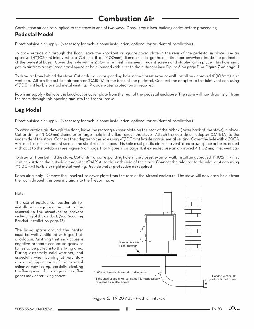
Combustion air can be supplied to the stove in one of two ways. Consult your local building codes before proceeding.
Pedestal Model
Direct outside air supply - (Necessary for mobile home installation, optional for residential installation.)
To draw outside air through the floor; leave the knockout or square cover plate in the rear of the pedestal in place. Use an approved 4”(102mm) inlet vent cap. Cut or drill a 4”(100mm) diameter or larger hole in the floor anywhere inside the perimeter of the pedestal base. Cover the hole with a 20GA wire mesh minimum, rodent screen and staple/nail in place. This hole must get its air from a ventilated crawl space or be extended with duct to the outdoors (see Figure 6 on page 11 or Figure 7 on page 11
To draw air from behind the stove. Cut or drill a corresponding hole in the closest exterior wall. Install an approved 4”(102mm) inlet vent cap. Attach the outside air adapter (OAIR.1A) to the back of the pedestal. Connect the adapter to the inlet vent cap using 4”(100mm) fexible or rigid metal venting. . Provide water protection as required.
Room air supply - Remove the knockout or cover plate from the rear of the pedestal enclosure. The stove will now draw its air from the room through this opening and into the firebox intake
Leg Model
Direct outside air supply - (Necessary for mobile home installation, optional for residential installation.)
To draw outside air through the floor; leave the rectangle cover plate on the rear of the airbox (lower back of the stove) in place. Cut or drill a 4”(100mm) diameter or larger hole in the floor under the stove. Attach the outside air adapter (OAIR.1A) to the underside of the stove. Connect the adapter to the hole using 4”(100mm) fexible or rigid metal venting. Cover the hole with a 20GA wire mesh minimum, rodent screen and staple/nail in place. This hole must get its air from a ventilated crawl space or be extended with duct to the outdoors (see Figure 6 on page 11 or Figure 7 on page 11. if extended use an approved 4”(102mm) inlet vent cap
To draw air from behind the stove. Cut or drill a corresponding hole in the closest exterior wall. Install an approved 4”(102mm) inlet vent cap. Attach the outside air adapter (OAIR.1A) to the underside of the stove. Connect the adapter to the inlet vent cap using 4”(100mm) fexible or rigid metal venting. Provide water protection as required.
Room air supply - Remove the knockout or cover plate from the rear of the Airboxl enclosure. The stove will now draw its air from the room through this opening and into the firebox intake
Non-combustibleFloor Protector
Hooded vent or 90° elbow turned down.
* 100mm diameter air inlet with rodent screen
* If the crawl space is well ventilated it is not necessary to extend air inlet to outside
Note:
The use of outside combustion air for installation requires the unit to be secured to the structure to prevent dislodging of the air duct. (See: Securing Bracket Installation page 13) The living space around the heater must be well ventilated with good air circulation. Anything that may cause a negative pressure can cause gases or fumes to be pulled into the living area. During extremely cold weather, and especially when burning at very slow rates, the upper parts of the exposed chimney may ice up, partially blocking the flue gases. If blockage occurs, flue gases may enter living space.
Figure 6. TN 20 AUS - Fresh air intake.ai
11 5055.552AS_040217-20 TN 20
Combustion Air
12 5055.552AS_040217-20TN 20
Operation
CAUTION: Never use gasoline, gasoline type lantern fuel, kerosene, charcoal lighter fluid or similar liquids to start or "freshen up" a fire in this heater. Keep all such liquids well away from the heater while it is in use.
CAUTION: Hot while in operation. Keep children, clothing and furniture away. Contact may cause skin burns.
WARNING: DO NOT USE FLAMMABLE LIQUIDS OR AEROSOLS TO START OR REKINDLE THE FIRE.
WARNING: DO NOT USE FLAMMABLE LIQUIDS OR AEROSOLS IN THE VICINITY OF THIS APPLIANCE WHEN IT IS OPERATING.
WARNING: DO NOT STORE FUEL WITHIN HEATER INSTALLATION CLEARANCES.
WARNING: DO NOT OPERATE THIS APPLIANCE AS AN OPEN FIRE.
WARNING: OPEN AIR CONTROL (AND DAMPER WHEN FITTED) BEFORE OPENING FIRING DOOR.
Your TRUE NORTH heater is designed for maximum overall efficiency at a moderate firing rate. Overfiring is hazardous and a waste of fuel. Too slow a burn contributes to creosote buildup and lowers combustion efficiency.
NOTE: Left and Right as referred to in this manual are considered your left and right when facing the front of the woodstove.
Wood Selection
This heater is designed to burn natural wood only. Higher efficiency and lower emissions generally result when burning air-dried seasoned hardwoods, as compared to softwoods or too green or freshly cut hardwoods.
Wood should be properly air dried (seasoned) for six months or more. Wet or undried wood will cause the fire to smoulder and produce large amounts of creosote. Wet wood also produces very little heat and tends to go out often.
DO NOT BURN :
• Salt water wood * • Treated wood • Wet or green wood • Coal/charcoal • Garbage/Plastic * • Solvents
* These materials contain chlorides which will rapidly destroy metal surfaces and void warranty.
Do not burn anything but wood. Other fuels (eg. charcoal) can produce large amounts of carbon monoxide, a tasteless, odourless gas that can kill. Under no circumstances should you attempt to barbecue in this heater.
This unit is not designed to be operated with the firing door open. In addition to the obvious hazard of sparks landing on combustibles, an open fire door will cause the heater to draw air from the living space and possibly cause suffocation in an air tight home.
13 5055.552AS_040217-20 TN 20
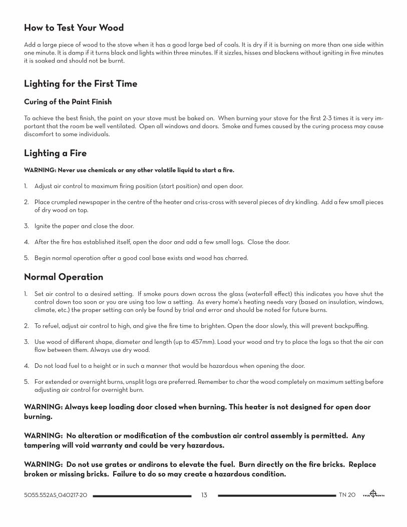
How to Test Your Wood
Add a large piece of wood to the stove when it has a good large bed of coals. It is dry if it is burning on more than one side within one minute. It is damp if it turns black and lights within three minutes. If it sizzles, hisses and blackens without igniting in five minutes it is soaked and should not be burnt.
Lighting for the First Time
Curing of the Paint Finish
To achieve the best finish, the paint on your stove must be baked on. When burning your stove for the first 2-3 times it is very im-portant that the room be well ventilated. Open all windows and doors. Smoke and fumes caused by the curing process may cause discomfort to some individuals.
Lighting a Fire
WARNING: Never use chemicals or any other volatile liquid to start a fire.
1. Adjust air control to maximum firing position (start position) and open door.
2. Place crumpled newspaper in the centre of the heater and criss-cross with several pieces of dry kindling. Add a few small pieces of dry wood on top.
3. Ignite the paper and close the door.
4. After the fire has established itself, open the door and add a few small logs. Close the door.
5. Begin normal operation after a good coal base exists and wood has charred.
Normal Operation
1. Set air control to a desired setting. If smoke pours down across the glass (waterfall effect) this indicates you have shut the control down too soon or you are using too low a setting. As every home's heating needs vary (based on insulation, windows, climate, etc.) the proper setting can only be found by trial and error and should be noted for future burns.
2. To refuel, adjust air control to high, and give the fire time to brighten. Open the door slowly, this will prevent backpuffing.
3. Use wood of different shape, diameter and length (up to 457mm). Load your wood and try to place the logs so that the air can flow between them. Always use dry wood.
4. Do not load fuel to a height or in such a manner that would be hazardous when opening the door.
5. For extended or overnight burns, unsplit logs are preferred. Remember to char the wood completely on maximum setting before adjusting air control for overnight burn.
WARNING: Always keep loading door closed when burning. This heater is not designed for open door burning.
WARNING: No alteration or modification of the combustion air control assembly is permitted. Any tampering will void warranty and could be very hazardous.
WARNING: Do not use grates or andirons to elevate the fuel. Burn directly on the fire bricks. Replace broken or missing bricks. Failure to do so may create a hazardous condition.

14 5055.552AS_040217-20TN 20
Restarting After Extended or Overnight Burns
1. Open door and rake hot embers towards the front of the heater. Add a couple of dry, split logs on top of embers, close door.
2. Adjust air control to high (left position) and in just a few minutes, logs should begin burning.
3. After wood has charred, reset air control to desired setting.
4. To achieve maximum firing rate, set control to high (left position). Do not use this setting other than for starting or preheating fresh fuel loads.
Proper Draft
1. Draft is the force which moves air from the appliance up through the chimney. The amount of draft in your chimney depends on the length of the chimney, local geography, nearby obstructions and other factors.
2. Too much draft may cause excessive temperatures in the appliance. An uncontrollable burn or a glowing red stove part or chimney indicates excessive draft.
3. Inadequate draft may cause backpuffing into the room and plugging of the chimney. Smoke leaking into the room through appliance and chimney connector joints indicates inadequate draft.
Ash Removal
Whenever ashes get 75 mm to 100 mm inches deep in your firebox, and when the fire has burned down and cooled, remove excess ashes. Leave an ash bed approximately (25 mm) deep on the firebox bottom to help maintain a hot charcoal bed.
Disposal of Ashes
Ashes should be placed in a metal container with a tight fitting lid. The closed container of ashes should be placed outside on a non-combustible floor or on the ground, well away from all combustible materials, pending final disposal. If the ashes are disposed of by burial in soil or otherwise locally dispersed, they should be retained in a closed container until all cinders have thoroughly cooled. Other waste should not be placed in this container.
DO NOT OVERFIRE THIS HEATER: Attempts to achieve heat output rates that exceed heater design specifications can result in permanent damage to the heater and chimney.
CAUTION: Ashes are to be removed only when the heater is cold.
15 5055.552AS_040217-20 TN 20
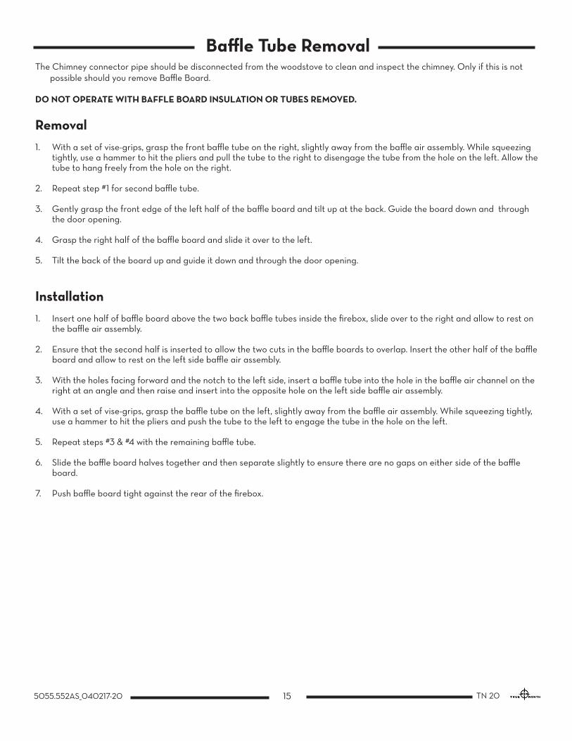
Baffle Tube RemovalThe Chimney connector pipe should be disconnected from the woodstove to clean and inspect the chimney. Only if this is not
possible should you remove Baffle Board.
DO NOT OPERATE WITH BAFFLE BOARD INSULATION OR TUBES REMOVED.
Removal1. With a set of vise-grips, grasp the front baffle tube on the right, slightly away from the baffle air assembly. While squeezing
tightly, use a hammer to hit the pliers and pull the tube to the right to disengage the tube from the hole on the left. Allow the tube to hang freely from the hole on the right.
2. Repeat step #1 for second baffle tube.
3. Gently grasp the front edge of the left half of the baffle board and tilt up at the back. Guide the board down and through the door opening.
4. Grasp the right half of the baffle board and slide it over to the left.
5. Tilt the back of the board up and guide it down and through the door opening.
Installation1. Insert one half of baffle board above the two back baffle tubes inside the firebox, slide over to the right and allow to rest on
the baffle air assembly.
2. Ensure that the second half is inserted to allow the two cuts in the baffle boards to overlap. Insert the other half of the baffle board and allow to rest on the left side baffle air assembly.
3. With the holes facing forward and the notch to the left side, insert a baffle tube into the hole in the baffle air channel on the right at an angle and then raise and insert into the opposite hole on the left side baffle air assembly.
4. With a set of vise-grips, grasp the baffle tube on the left, slightly away from the baffle air assembly. While squeezing tightly, use a hammer to hit the pliers and push the tube to the left to engage the tube in the hole on the left.
5. Repeat steps #3 & #4 with the remaining baffle tube.
6. Slide the baffle board halves together and then separate slightly to ensure there are no gaps on either side of the baffle board.
7. Push baffle board tight against the rear of the firebox.

16 5055.552AS_040217-20TN 20
17 5055.552AS_040217-20 TN 20
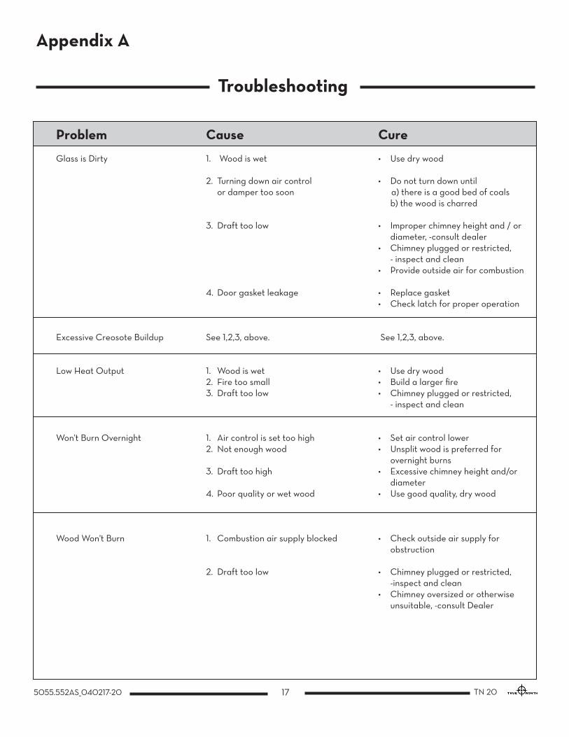
Problem Cause Cure
Glass is Dirty 1. Wood is wet • Use dry wood
2. Turning down air control • Do not turn down until or damper too soon a) there is a good bed of coals b) the wood is charred
3. Draft too low • Improper chimney height and / or diameter, -consult dealer • Chimney plugged or restricted, - inspect and clean • Provide outside air for combustion
4. Door gasket leakage • Replace gasket • Check latch for proper operation
Excessive Creosote Buildup See 1,2,3, above. See 1,2,3, above.
Low Heat Output 1. Wood is wet • Use dry wood 2. Fire too small • Build a larger fire 3. Draft too low • Chimney plugged or restricted, - inspect and clean
Won't Burn Overnight 1. Air control is set too high • Set air control lower 2. Not enough wood • Unsplit wood is preferred for overnight burns 3. Draft too high • Excessive chimney height and/or diameter 4. Poor quality or wet wood • Use good quality, dry wood
Wood Won't Burn 1. Combustion air supply blocked • Check outside air supply for obstruction 2. Draft too low • Chimney plugged or restricted, -inspect and clean • Chimney oversized or otherwise unsuitable, -consult Dealer
Troubleshooting
Appendix A

18 5055.552AS_040217-20TN 20
Replacement Parts - TN 20WHEN ORDERING, INCLUDE PART NUMBER WITH DESCRIPTION
The replacement parts are the same for the leg model.
1a,1b Side Shield Kit, Set L&R, ..................................................................................... TRNO.20SSA 2a Baffle Board (2pcs.) .................................................................................................. TRNO.BAFF 2b Baffle Tube Set (4pcs.) ...................................................................................TRNO.50001101 3 Door Casting Assy (c/w Handle) .........................................................................TRNO.DRBK 4 Replacement Glass (c/w gasket) ........................................................................ TRNO.7025 5 Door Gasket .................................................................................................................TN19.DGKIT 6 Glass Clamps (4 pcs.) .............................................................................................. TRNO.7608 7 Firebrick Set 9” x 4 1/2” x 1 1/4” (20 pcs.) ........................................................TRNO.BRIC 8 Rear Brick Rail (c/w 2 screws) ................................................................................TRNO.7625 9 Quadrant Assembly.....................................................................................................TRNO.7617 10 Fan (Optional) .............................................................................................TRNO.19EU.BLOWA 11 Flame Shield ..................................................................................................................TRNO.7610 12 Secondary Air Chamber, Left ........................................................................... TRNO.747511 13 Secondary Air Chamber, Right ........................................................................ TRNO.747510
ITEM DESCRIPTION PART NO.
10
1a
2a
2b
1b3
4
5
6
7
8
911
13
12

TN 20A
WHEN TESTED IN ACCORDANCE WITH: AS/NZS 4012:2014 & AS/NZS4013:2014
ASFT16045-1 30 JAN. 2017
FREEESTANDINGTested by: AUSTRALIAN SOLID FUEL TESTING PTY LTD 3 GARDEN STREET, MORWELL, VICTORIA
MAXIMUM AVERAGE HEAT OUTPUT BURNING HARDWOOD5.4 kW
OVERALL AVERAGE EFFICIENCY BURNING HARDWOOD64%
PARTICULATE EMISSIONS FACTOR - 1.6g/kgCATALYTIC COMBUSTOR - NO
Distributed by: PIVOT STOVES AND HEATING CO234-238 MOORABOOL STREET, GEELONG, VIC 3220
pivotstove.com.au
04/11/16 5050.852AS
19 5055.552AS_040217-20 TN 20
Compliance Plate
Compliance plate is located at the rear of the TN 20

© 2016 Copyright Pacific Energy Fireplace Products LTD
Reproduction, adaptation, or translation without prior written permission is prohibited, except as allowed under the copyright laws.
PACIFIC ENERGY FIREPLACE PRODUCTS LTD.
Web site: www.pacificenergy.net2975 Allenby Rd., Duncan, BC V9L 6V8
PRINTED IN CANADA