installation and operating instructions/media/resources/ametek... · the instructions in this...
TRANSCRIPT

A Leader in Level Measurement
For Assistance Call 1-800-527-6297 Outside North America + 215-674-1234
Installation andOperating Instructions
CM6 Cut Monitor with HART® Protocol
U.S. and Canada: 1-800-553-909224-Hour Service: 1-800-527-6297International: +1 215-674-1234Fax: +1 215-674-2731E-mail: [email protected] Website: www.drexelbrook.com

AMETEK Drexelbrook makes no warranty of any kind with regard to the material contained in this manual, including, but not limited to, implied warranties or fitness for a particular purpose. Drexelbrook shall not be liable for errors contained herein or for incidental or consequential damages in connection with the performance or use of material.
Copyright 2007 AMETEK Drexelbrook
CM6 Cut Monitor with HART® Protocol
EDO# 01-07-108CM6-LMIssue #3
205 Keith Valley Road, Horsham, PA 19044 U.S. and Canada: 1-800-553-909224-Hour Service: 1-800-527-6297International: +1 215-674-1234Fax: +1 215-674-2731E-mail: [email protected] Website: www.drexelbrook.com
An ISO 9001 Certified Company


�
Table of Contents
Section 1: Introduction ...................................................................................................1 1.1 System Description ........................................................................................1 1.2 Unpacking.......................................................................................................1 1.3 Model Numbering ...........................................................................................2
Section 2: Installation ....................................................................................................3 2.1 Installation Guide ............................................................................................3 2.2 Installation Considerations .............................................................................5 2.3 Probe Insertion and Active Lengths ...............................................................6 2.4 Mounting the Electronic Unit ..........................................................................7 2.5 Wiring the Electronic Unit ..............................................................................8 2.6 Wiring the Sensing Element (Remote Electronic Units) ...............................10 2.7 Surge Voltage (Lightning) Protection ............................................................11 2.8 RFI (Radio Frequency Interference) .............................................................11
Section 3: Configuration & Calibration w/Drexelbrook Software ...........................13 3.1 General Description ......................................................................................13 3.2 Model Number ..............................................................................................13 3.3 System Requirements ..................................................................................13 3.4 Installing The HART® Modem ......................................................................14 3.5 Installing HARTWin Software .......................................................................16 3.6 Description of Function Keys ........................................................................16 3.7 Configuration ................................................................................................18 3.8 Calibration ....................................................................................................19 3.9 Set D/A Trim .................................................................................................25 3.10 Digital Integral Meter Configuration ..............................................................26 3.11 Save/Print Entries .........................................................................................27 3.12 Calibration & Configuration via 401-44-3 Display/Keypad ............................28
Section 4: Specifications ...............................................................................................31
Section 5: Normal Maintenance ..................................................................................33 5.1 Viewport Cleaning ........................................................................................33
Section 6: Drawings .....................................................................................................35 6.1 Mounting & Dimensional Drawings ...............................................................35 6.2 FM Control Drawings ....................................................................................39 6.3 CSA Control Drawings ..................................................................................56

Section 1

Introduction
�
Section 1: Introduction
1.1 System Description
The instructions in this manual are for the AMETEKDrexelbrookCM6seriesCutMonitorformeasurementofthepercentageofwaterinoil.EachAMETEKDrexelbrookCM6seriessystemconsistsofatwo-wire,4-20mAelectronicunitanda700seriessensingelement.Communicationwiththede�iceisdonebyeitheranonboardkeypadorwithalaptop�iaHART®protocol.
AMETEKDrexelbrookhasbeenmeasuringwatercutwithcapaciti�etechnologyforo�er40years.Usingcapacitancetomeasurewatercutiswidelysuccessfulbecauseofthelargedifference between the dielectric constants of oil (k≈2.3) and water (k≈80). The sensing element and the pipe wall form thenecessary twoplatesof theconcentric capacitor.Thesystem electronics transmit a radio frequency �oltage tothesensingelementthatmeasureschangesincapacitance.As the amount of water in the flowing oil increases, the net dielectric of the fluid increases which causes the capacitance toincrease.Theonboardelectronicscanthencomputetherelationshipbetweencapacitancechangeandwatercut.Itistermedatwo-wiretransmitterbecausethesametwowiresthatareusedtopowertheunitalsoindicatethechangeinCut (4-20 mA).
1.2 Unpacking
Carefullyremo�ethecontentsofthecartonandcheckeachitemagainstthepackinglistbeforedestroyinganypackingmaterial. If there is any shortage or damage, report itimmediatelytothefactory.
CM6™ Cut Monitor
�
MountingAO .75" 316 SS NPTBA 1" 150# RF CSBB 1" 150# RF 316/316L SSCB 1" 300# 316/316L SSDA 1.5" 150# RF CSDB 1.5" 150# RF 316/316L SSEA 1.5" 300# CSEB 1.5" 300# RF 316/316L SSFA 2" 150# RF CSFB 2" 150# RF 316/316L SSGA 2" 300# RF CS
GB 2" 300# RF 316/316L SSIA 3" 150# RF CSIB 3" 150# RF 316/316L SSKB 4" 150# RF 316/316L SSLA 4" 150# RF CSLB 4" 150# RF 316/316L SSMA 6" 150# RF CSMB 6" 150# RF 316/316L SSNA 6" 300# RF CSNB 6" 300# RF 316/316L SSXX Mounting Not Listed
Insertion LengthX X X X X Determined By Factory
Mounting0 Integral1 Remote - no cable2 Remote - 10 feet cable GP3 Remote - 25 feet cable GP4 Remote - 35 feet cable GP5 Remote - 50 feet cable GP
Sensing Element0 700-1202-0014 700-1202-0415 700-1202-081 (M0303)A 700-1202-061B 700-1202-081
6 Remote - 75 feet cable GP7 Remote - 100 feet cable GP8 Remote (25 feet) tri-ax cable9 Remote (50 feet) tri-ax cableA Remote (75 feet) tri-ax cableB Remote (100 feet) tri-ax cable
C Remote (10 feet) high temp cableD Remote (25 feet) high temp cableE Remote (35 feet) high temp cableF Remote (50 feet) high temp cableG Remote (75 feet) high temp cableH Remote (100 feet) high temp cable
Filters0 No Filters1 RFI Filter4 Loop Surge Filter7 Loop Filter and Surge Filter
Pipe Size1 1" Pipe2 2" Pipe3 3" Pipe4 4" Pipe
6 6" Pipe8 8" or Larger PipeT In Tank Sensor
Cote-Shield Length0 2 . 0 2" CSL0 3 . 5 3.5" CSL1 0 . 0 10" CSL
TechnologyRCT-161 CM6 Cut Monitor
Electronics
Calibration0 No Pre-CalibrationA 0 to 1% Light OilB 0 to 5% Light OilC 0 to 10% Light Oil
D 0 to 30% Light OilE 0 to 50% Light OilF 0 to 1% Heavy OilG 0 to 5% Heavy Oil
H 0 to 10% Heavy OilI 0 to 30% Heavy OilJ 0 to 50% Heavy OilM 0 to 80% Heavy Oil
ApprovalsC CSA Intrinsically Safe ApprovalD CSA Explosion Proof with IS Barriers
F FM Intrinsically Safe ApprovalG FM Explosion Proof with IS barriers
R T 1 6 1 0C
1.3 Model Numbering

Installation
�
Section 2: Installation
2.1 Installation Guide
Use the followingmountingand installation instructionsso that the sensing element will operate properly andaccurately:
• Thesensingelementshouldbemountedinasectionofpipeasclosetothecenterandasparalleltothepipeaspossible.Factory calibrationassumesmountingonthepipecenterlineandinthecorrectsizepipe.
• Verticalmounting,withthetipdown,ispreferred,
butnotessential. • Gasbubblesmustbeexcludedfromtheacti�earea
bymaintainingpressureand,ifnecessary,adegasserupstream from the sensing element. Gas bubbles(whether from natural gas, air or steam) decrease the accuracyofthemeasurement.
• Donottakethesensingelementapartorloosenthe
packingglands. • For in-tank mounting installations, the standard
lengthofthecoteshieldsectioniseightinches.Ifthenozzleislongerthansixinches,anon-standardcoteshieldlengthshouldbeused.
• In large pipe installations (greater than eight inches),
the length of the cote shield section must be longenough (i.e. length of nozzle short enough) that the cutout in the concentric tube is in the actual flow of oil.
• For large pipes with no bends (18 inch and larger), itispossibletomountthesensingelementata45degree angle to provide sufficient flow through the shieldofthesensingelement.

CM6™ Cut Monitor
�
2.1 Installation Guide (Continued)
Installation in a Pipe 8 inches or larger
Installation in a Pipe 18 inches or larger

Installation
�
2.2 Installation Considerations
The sensing element must be mounted at an existing orcreated, 90 degree bend in the pipe. It can be installedthrough a tee or a weld-o-let to a 90 degree elbow. The�erticallydownwardmountingattitudeispreferredforeaseofinspectionorcleaning,sincedrainingofthepipeisnotrequired.Regardless,theprobewillfunctioninanyattitude,aslongasthepipeiscompletelyfullintheacti�eprobearea.See the figure below for ideal installation orientation.
Theprobeisacti�efromitstiptotheendoftheCote-Shieldelement. In the area of the Cote-Shield, it is completelyinacti�e.
Inallcases,thepresenceofgasbubbles,whetherfromair,petroleum�apor,steam,ornaturalgas,willreduceaccuracy,producinglowerreadings.Oneofthemostcommoncausesofgasbubblesisabruptpressuredropsinhightemperaturestreams, which can allow water and light ends to flash.
Anin-linemixerjustupstreamoftheCutMonitorishighlyrecommendedforstreamswhichgoabo�e10%.Accuracyisbasedonuniform,oil-continuousemulsion,soanyunplannedseparationwillcausea�oidableerrors.
All instruments are factory calibrated. If calibrationtrimmingisrequired,itmaybedonethroughtheKeypadorwithAMETEKDrexelbrookPCsoftware.Theproprietarysoftware allows one shot calibration trimming with onereadingandsample.TheReal-timeViewwindowisusefulforobser�ingtransmitterfunctionandtroubleshooting.
DREXELBROOK
Suggested Installation
CM6™ Cut Monitor
6
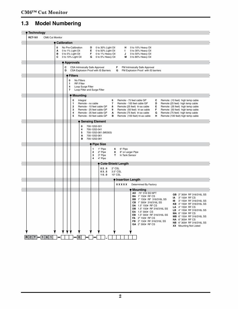
Pipe ID Probe Diameter Cote Shield Length Active Length Insertion Length1 0.375 2 10.40 12.40
2 0.375 2 17.76 19.76
3 0.375 2 22.06 24.06
4 0.375 2 25.11 27.11
5 0.375 2 27.47 29.47
6 0.375 2 29.41 31.41
7 0.375 2 31.04 33.04
1 0.375 3.5 10.40 13.90
2 0.375 3.5 17.76 21.26
3 0.375 3.5 22.06 25.56
4 0.375 3.5 25.11 28.61
5 0.375 3.5 27.47 30.97
6 0.375 3.5 29.41 32.91
7 0.375 3.5 31.04 34.54
1 0.375 10 10.40 20.40
2 0.375 10 17.76 27.76
3 0.375 10 22.06 32.06
4 0.375 10 25.11 35.11
5 0.375 10 27.47 37.47
6 0.375 10 29.41 39.41
7 0.375 10 31.04 41.04
Probe Diameter for Peek is 3/8” 8” and larger pipes require a concentric
2.3 Probe Insertion and Active Lengths

Installation
�
2.4 Mounting the Electronic Unit
The integralelectronicunit ismountedwith thesensingelement. The remote electronic unit is designed for field mounting,but itshouldbemounted ina locationas freeaspossiblefrom�ibration,corrosi�eatmospheres,andanypossibilityofmechanicaldamage.Forcon�enienceatstart-up,mounttheinstrumentinareasonablyaccessiblelocation.Ambient temperatures should be between -40°F and 185°F (-40°C and 85°C).
When installing conduit to the electronic unit, be surethat�erticalconduitrunswillnotcausewatertoentertheelectronicunithousing,asshowninFigureBelow.
Recommended Conduit Connections
CM6™ Cut Monitor
�
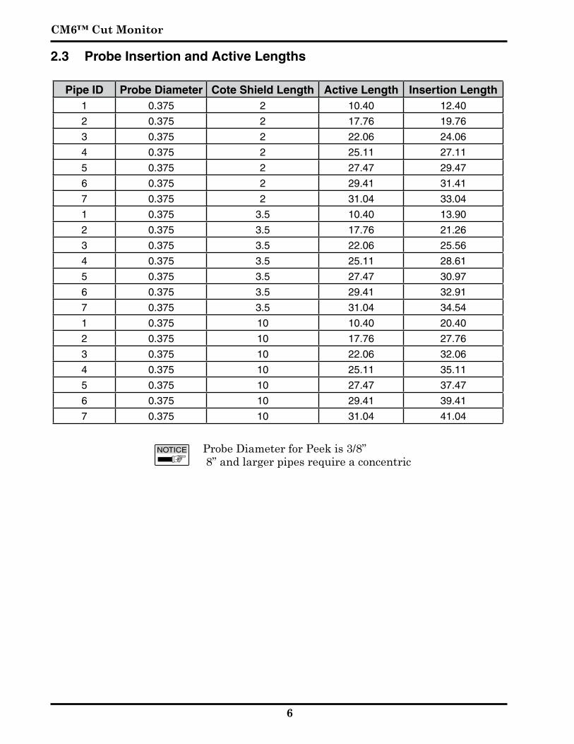
2.5 Wiring the Electronic Unit
CAUTION: BeforeusingIntrinsicSafetyBarriers,readthemanufacturer's
instructionforbarrieroperation.
CAUTION: If welding anywhere on the piping or connected tanks,
physicallyremo�eallconnectionsfromtheelectronicunitandremo�etheunitfromitshousing.
Integralunitsareprewiredatthefactory.TheFigureBelowshowsthewiringoftheintegralunit.
CM6 Wiring Connections(Integral Mounting)
GROUND PROBEPAD SHDCAP
GND V - V +M -
GROUND PROBEPAD SHD
Shield Wire (Red)
Center Wire (Blue)
Three Terminal Sensing Element
- To Signal
+ To Signal
AlwaysInstallperControlDrawings
Installation
�
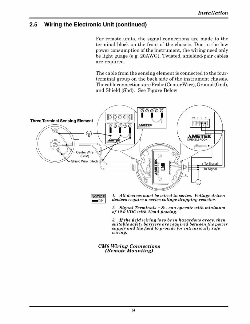
Forremoteunits,thesignalconnectionsaremadetotheterminalblockonthefrontofthechassis.Duetothelowpowerconsumptionoftheinstrument,thewiringneedonlybe light guage (e.g. 20AWG). Twisted, shielded-pair cables arerequired.
Thecablefromthesensingelementisconnectedtothefour-terminalgrouponthebacksideoftheinstrumentchassis.The cable connections are Probe (Center Wire), Ground (Gnd), and Shield (Shd). See Figure Below
2.5 Wiring the Electronic Unit (continued)
CM6 Wiring Connections(Remote Mounting)
GND V - V +M -
GROUND PROBEPAD SHDCAP
GROUND PROBEPAD SHD
Three Terminal Sensing Element
Shield Wire (Red)
Center Wire (Blue)
- To Signal
+ To Signal
1. All devices must be wired in series. Voltage driven devices require a series voltage dropping resistor.
2. Signal Terminals + & - can operate with minimum of 12.0 VDC with 20mA flowing.
3. If the field wiring is to be in hazardous areas, then suitable safety barriers are required between the power supply and the field to provide for intrinsically safe wiring.

CM6™ Cut Monitor
�0
2.6 Wiring the Sensing Element (Remote Electronic Units)
Three-Terminal Cable Connections to Three-Terminal Sensing Element
OnlycoaxialcablessuppliedbyAMETEKDrexelbrookshouldbeusedtoconnectthetransmittertothesensingelement.Useofothercablescanresultinunstablecalibration.
Topre�entproblemswithradiofrequencyinterferencethecable should be run in metallic conduit if walkie-talkiesor�ariablespeeddri�esare locatedwithin25feetof theelectronicunit.
ThecableconnectionstothesensingelementareshowninFigureBelow
Donotconnectthecabletothesensingelementuntilafterthe sensingelementhasbeen installedand the condulethousinghasbeensecured.
Installation
��
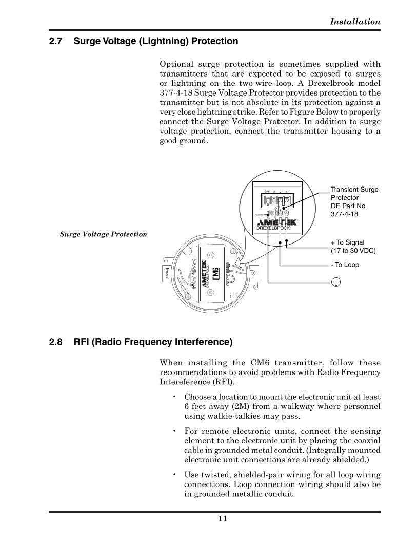
Optional surge protection is sometimes supplied withtransmitters that are expected to be exposed to surgesor lightning on the two-wire loop. A Drexelbrook model377-4-18 Surge Voltage Protector provides protection to the transmitterbutisnotabsoluteinitsprotectionagainsta�erycloselightningstrike.RefertoFigureBelowtoproperlyconnecttheSurgeVoltageProtector.Inadditiontosurge�oltage protection, connect the transmitter housing to agoodground.
2.7 Surge Voltage (Lightning) Protection
2.8 RFI (Radio Frequency Interference)
When installing the CM6 transmitter, follow theserecommendationstoa�oidproblemswithRadioFrequencyIntereference (RFI).
• Choosealocationtomounttheelectronicunitatleast6 feet away (2M) from a walkway where personnel usingwalkie-talkiesmaypass.
• For remote electronic units, connect the sensingelementtotheelectronicunitbyplacingthecoaxialcableingroundedmetalconduit.(Integrallymountedelectronic unit connections are already shielded.)
• Usetwisted,shielded-pairwiringforallloopwiringconnections.Loopconnectionwiringshouldalsobeingroundedmetallicconduit.
Surge Voltage Protection
GND V - V +M -
SERIAL NO.MODEL NO.
YEAR OF MANUFACTURE
+ To Signal (17 to 30 VDC)
- To Loop
Transient Surge ProtectorDE Part No. 377-4-18

CM6™ Cut Monitor
��
2.8 RFI (Radio Frequency Interference) (continued)
• Donotrunpowerwiringinthesameconduitwith signalcables
• Groundtheelectronicunitandhousingwithaminimumof14gaugewiretoagoodearthground.Make sure that conduits entering and lea�ing thehousingha�eagoodelectricalgroundconnectiontothehousing.
TheRFIrecommendationslistedabo�epro�ideadegreeof protection that is usually sufficient to protect against walkie-talkies used 3 feet (1M) or more from atypicalelectronicunit.
SHLD
GND
CW
POS +
NEG -
GND
GND V - V +M -
GROUND PROBEPAD SHD
CAP
GROUND PROBEPAD SHD
- To Signal
+ To Signal
Radio Frequency Interference (RFI) Filters

Configuration & Calibration
��
Section 3: Configuration & Calibration w/ Drexelbrook Software
ThissectioninstructstheuserhowtousetheDrexelbrook401-700-20/40 Series PC calibrator software to configure and calibrate the CM6 (RF Admittance) Transmitter.
3.1 General Description
The 401-700-20/40 software package allows the use of any Windows® 9X/NT/2000/XP-based personal, laptop, or notebook computer to calibrate the HART Protocoltransmitter.
The CM6 requires HARTWin™ Software �ersion 2.5 orgreater.
3.2 Model Number
� 0 � - 0 � 0 0 - 0 � X / � X 2X=21 PC Software Package includes: RS232 Modem
Assembly 401-0700-004 (Figure 3.1).
2X=22PCSoftwarePackageincludes: Contentsin401-0700-021andHARTWin™�ersion2.1or
greateronaCD-ROM.
4X=41PCSoftwarePackageincludes: USB Modem Assembly 401-0700-007(Figure 3.1a).
4X=42PCSoftwarePackageincludes: Contentsin401-0700-41,UtilitiesandDri�ersonaCD-ROM,
andHARTWin™onaCD-ROM.
� 0 � - 0 � 0 0 - 0 � � HARTWin™onaCD-ROM.
3.3 System Requirements
PC Requirements Windows® 95, 98, ME, 2000, XP. The USB modem is not compatible with Windows® 95, 98
First Edition, or NT. It is recommended that the software beinstalledonaharddri�ewith20megabytesormoreofspacea�ailable.
Input to Modem RS232 or USB Port, from one of the COM serial ports (COM1,
COM2, etc.). The PC provides operating power for the modem butnotforthetransmitter.
Output (to Transmitter being Calibrated) 4-20mAinHART®Protocol.
CM6™ Cut Monitor
��
3.4.1 Installing The RS232 Modem
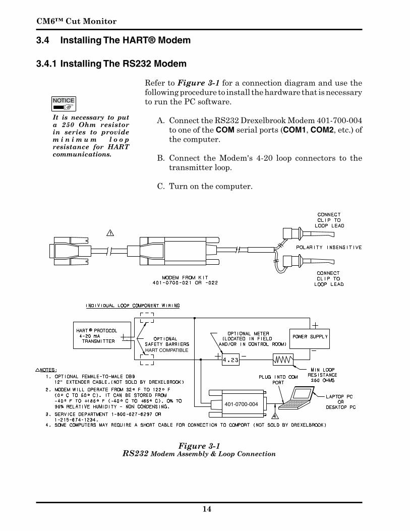
RefertoFigure 3-1foraconnectiondiagramandusethefollowingproceduretoinstallthehardwarethatisnecessarytorunthePCsoftware.
A. Connect the RS232 Drexelbrook Modem 401-700-004 tooneoftheCOMserialports(COM1,COM2, etc.) of thecomputer.
B. Connect the Modem's 4-20 loop connectors to thetransmitterloop.
C.Turnonthecomputer.
Figure 3-1 RS232 Modem Assembly & Loop Connection
HART COMPATIBLE
401-0700-004
3.4 Installing The HART® Modem
It is necessary to put a 250 Ohm resistor in series to provide m i n i m u m l o o p resistance for HART communications.

Configuration & Calibration
��
Notes:
1. Modem will operate from 32º F to 122º F (0º C to 50º C). It can be stored from -40º F to +185º F (-40º C to +85º C). 0% to 95% relative humidity - non condensing.
2. Servic Department 1-800-527-6297 or 1-215-674-1234
USB
Figure 3-1a USB Modem Assembly & Loop Connection
401-0700-007
3.4.2 Installing The USB Modem
Refer to Figure 3-1a for a connection diagram and use the followingproceduretoinstallthehardwarethatisnecessarytorunthePCsoftware.
A. Turnonthecomputer B. InstallModemSoftware:
• ItishighlyrecommendedtheUSBdri�ersbeinstalledBEFOREyoupluginthemodem.
• Install the USB Dri�ers by inserting the ModemInstallationDiskintoCDDri�eofthecomputer.
• If program does not "Auto-Run", select "D:\setup"(where D is the letter representing the CD Drive)
• Be Sure to Select the USB interface in the setupprompt.
• Followany"On-Screen"Instructions.
C. Connect the Drexelbrook Modem 401-700-007 to a USB port on the computer. With the USB dri�ers alreadyinstalled,thecomputerwilldetectthemodem andassignaCOMPORTnumber.
D. ConnecttheModem's4-20loopconnectorstothe transmitterloop.
HART COMPATIBLE
It is necessary to put a 250 Ohm resistor in series to provide m i n i m u m l o o p resistance for HART communications.
CM6™ Cut Monitor
�6
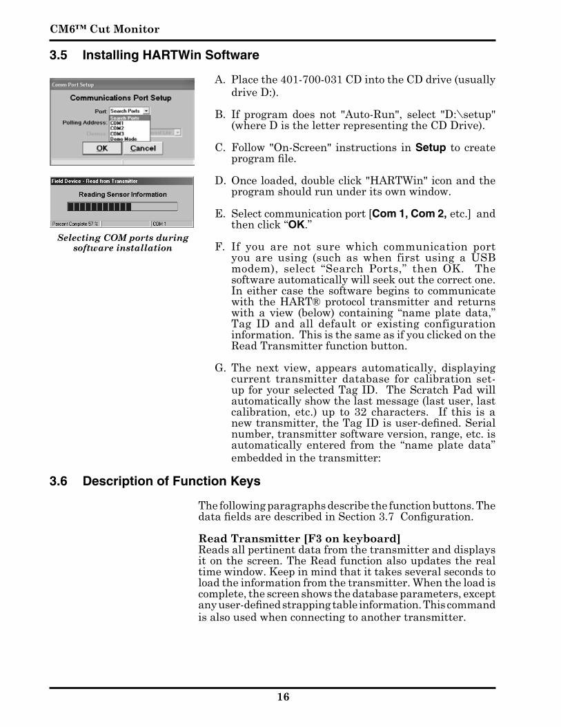
3.5 Installing HARTWin Software
A. Place the 401-700-031 CD into the CD drive (usually drive D:).
B. If program does not "Auto-Run", select "D:\setup"(where D is the letter representing the CD Drive).
C. Follow"On-Screen" instructions inSetup tocreateprogram file.
D. Onceloaded,doubleclick"HARTWin"iconandtheprogramshouldrununderitsownwindow.
E. Selectcommunicationport[Com 1, Com 2, etc.]andthenclick“OK.”
F. If you are not sure which communication portyou are using (such as when first using a USBmodem), select “Search Ports,” then OK. The softwareautomaticallywillseekoutthecorrectone.Ineithercase thesoftwarebegins tocommunicatewith theHART®protocol transmitterand returnswith a view (below) containing “name plate data,” Tag ID and all default or existing configurationinformation.ThisisthesameasifyouclickedontheReadTransmitterfunctionbutton.
G. The next �iew, appears automatically, displayingcurrent transmitter database for calibration set-upforyourselectedTagID.TheScratchPadwillautomaticallyshowthelastmessage(lastuser,lastcalibration, etc.) up to 32 characters. If this is a new transmitter, the Tag ID is user-defined. Serial number,transmittersoftware�ersion,range,etc.isautomatically entered from the “name plate data” embeddedinthetransmitter:
3.6 Description of Function Keys
Thefollowingparagraphsdescribethefunctionbuttons.Thedata fields are described in Section 3.7 Configuration.
Read Transmitter [F� on keyboard] Readsallpertinentdatafromthetransmitteranddisplays
itonthescreen.TheReadfunctionalsoupdatestherealtimewindow.Keepinmindthatittakesse�eralsecondstoloadtheinformationfromthetransmitter.Whentheloadiscomplete,thescreenshowsthedatabaseparameters,exceptany user-defined strapping table information. This command isalsousedwhenconnectingtoanothertransmitter.
Selecting COM ports during software installation

Configuration & Calibration
��
3.6 Description of Function Keys (Continued) Write to Transmitter [F� on keyboard] Sends new or edited configuration data to the transmitter.
Data fields that have been edited but not sent to the transmitteraredisplayedinred.
Real Time View [F� on keyboard] Displaystherealtime�aluesofwaterpercentage,capacity,
loopcurrent,andstatus.
D/A Trim Allows a field reference meter to be connected to the
transmitter for adjusting transmitter output current.See Section 3.9.
Strapping Table Displays the values of the input (pF) vs. output (% water) in
atableofupto21-points.Allowspointstobeadjustedwhenactual data deviated from the theoretical input/output curve. See Section 3.8.4
Configure Meter Configures the Digital Integral Meter (440-44-3) used for
local indication. See Section 3.10
Cut Monitor Calibration (One-Shot®) Used to adjust calibration to specific oil and temperature
thatthetransmittermonitors.See Section 3.8.1
HARTWin Tool Bar

CM6™ Cut Monitor
��
3.7 Configuration
Configuration involves downloading information to the HART protocol transmitter that is specific to the application that isbeingmeasured.
Calibration requires that application information andtwo points of level and/or capacitance be supplied to the transmitterfromthecalibrationsoftware.
A. Begin configuration by using Tag ID (8 characters) toidentifytheunitor�essel.UsetheScratchpad(32 characters) to record the date of calibration or other similar notes. Press Tab or Enter on yourkeyboard.
B. EditDamping Timefrom0-90seconds,ifdesired.
C. ClickonWrite to Transmitter.
HARTWin Main Screen

Configuration & Calibration
��
3.8 Calibration
AllDrexelbrookCM6SeriesCutMonitorinstrumentsarecalibratedatthefactoryaccordingto:
• sizeofpipe,and• densityofoil
Specific factors could cause the factory calibration to be less accuratethanisrequired.Forexample,
a. Pipe I.D. is smaller than nominal size (Sched. 80, 160, or extra heavy pipe)
b. Sensing element is not centered (parallel to axis) in pipe. This condition causes higher (never lower) readings.
c. Oil may be heavier (higher readings) or lighter (lower readings) than expected.
d.Majortemperaturede�iations.
Donotchangethefactorycalibrationwithoutobtainingdatathatindicatesacalibrationchangeisnecessary.Iftheoutputreadingislowbecauseofgas,steam,orairinthestream,then no amount of calibration will produce satisfactoryperformance. Consult the factory at 1-800-527-6297.
Once the gas is gone, an accurate calibration check canbemade.Thefollowingequipmentisrequiredtocheckthecalibrationofacutmonitorapplicationandrecordsampledata:
• A centrifuge (or other API-approved standard) to samplewatercontent.
• If the stream temperature is greater than 150ºF(65ºC), a sampling bomb with a minimum capacity of500ml.
• Temperaturestabilizationbath.

CM6™ Cut Monitor
�0
3.8.1 One Shot ® Calibration Trim Using HARTWin Software
a. WithaPCconnectedtothesignalloop,clickontheReal Time View button to open the “Real Time View” Screen.
b. Take a sample of the fluid from as close to the probe as possible. Use a sampling bomb if the streamtemperatureisgreaterthan150°F.Stabilizeat150°Fbeforedeterminingwatercontent.
c. Read and record water percentage from the “RealTime View” as the sample is being taken.
d. After determining the actual water percentage inthe sample, close the “Real Time View” window and open the “Calibration Screen” by clicking on the Cut MonitorCalibrationbutton.
e. Enterthe%waterreading,recordedatthetimeofsampling in the “Indicated Water” box. Enter the result of the sample test in the “Sampled Water” box andclickontheCalibratebutton.
f. ClickontheWriteToTransmitterbuttontoinstallthere�isedcalibrationinthetransmitter.
g. Dependingontherange, if theoriginalcalibrationandthemeasuredsampledifferedbymorethan2.5%water,another iterationwillprobablyberequired.Unless there is an o�erwhelming discrepancy, itis best to monitor the performance with this newcalibration for a few days before making a secondchange.
RTV Window
Calibration Window

Configuration & Calibration
��
3.8.2 Use of Sample Bomb
Inordertogetaccuratesamplereadingsonthelinesrunninghotter than150°F, it isnecessary topre�entwater fromflashing off as steam. This requires a sampling “bomb” to capturethesampleunderpressure,followedbycoolingto150°F.
a. Connectthesamplingbombtothesampletap
b. Opentopandbottom�al�esonthebomb
c. Openthesampletapwithacatchbasinunderthebomb
d. Allowtheliquidtorunthroughthebombforatleast60seconds
e. Closethebottom�al�eonthebombandallowittofill
f. Closetopbomb�al�eandsampletap
g. Remo�ebombandplacein150°Fstabilizingbath
h. Oncetempisstabilizedat150°F,proceedwithnormaldeterminationofwater

CM6™ Cut Monitor
��
3.8.3 Range Change
It is always possible to reduce the span of an existingcalibration simply by lowering the % water URV on the“Menu Screen”. If the reduction in span is greater than 20 or 30% of range, better accuracy can be usually achieved by changing the input/output curve to a lower range
When changing ranges on the CM6 it is important tounderstand that the shape of the input/output curve may requirere�ision,aswellasthe100%point.Thesimplestwaytore-rangeaninstrumentistoselectadifferentinputcur�e.Be sure to set the correct “Range Jumper” position indicated bythecur�eselected.Thisprocedurecanbeperformedonaninstalledinstrumentorintheshop,withtheelectronicunititself.
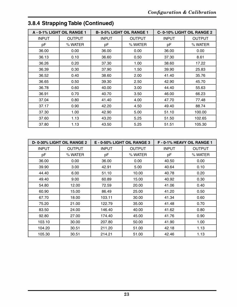
3.8.4 Strapping Table
If none of the available input/output curves are adequate for the application, a user defined table may have to be created. Thisisaccomplishedbyeditingthestrappingtable.
a. WhithaPCconnectedtothesignalloop(asinsection3.4) click on the strapping table button
b. ClickonWriteStrappingTablebuttontore-rangethetransmittertothenew�alues.
c. Click on the Exit to return to the “Menu Screen” It may be necessary to do a “One Shot” calibration on theinstalledinstrument.
For user defined tables it will be necessary to adjust the URV (920 mA) point to the desired range (see section 3.8.3) andadjustthelocalindicatorsothatthemaximum�alueisequal to themaximum%water in�iewing%water isdesired.ItmayalsobenecessarytoadjustthejumperstoputtheunitinthecorrectpFrange.
Captures from Main Screen
Configuration & Calibration
��
A - 0-1% LIGHT OIL RANGE 1 B- 0-5% LIGHT OIL RANGE 1 C- 0-10% LIGHT OIL RANGE 2
INPUT OUTPUT INPUT OUTPUT INPUT OUTPUT
pF % WATER pF % WATER pF % WATER
36.00 0.00 36.00 0.00 36.00 0.00
36.13 0.10 36.60 0.50 37.30 8.61
36.26 0.20 37.30 1.00 38.60 17.22
36.39 0.30 37.90 1.50 39.90 25.83
36.52 0.40 38.60 2.00 41.40 35.76
36.65 0.50 39.30 2.50 42.90 45.70
36.78 0.60 40.00 3.00 44.40 55.63
36.91 0.70 40.70 3.50 46.00 66.23
37.04 0.80 41.40 4.00 47.70 77.48
37.17 0.90 42.20 4.50 49.40 88.74
37.30 1.00 42.90 5.00 51.10 100.00
37.60 1.13 43.20 5.25 51.50 102.65
37.80 1.13 43.50 5.25 51.51 105.30
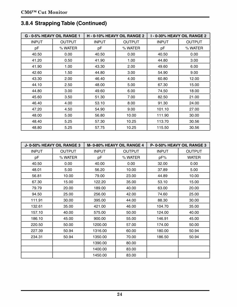
3.8.4 Strapping Table (Continued)
D- 0-30% LIGHT OIL RANGE 2 E - 0-50% LIGHT OIL RANGE 3 F - 0-1% HEAVY OIL RANGE 1
INPUT OUTPUT INPUT OUTPUT INPUT OUTPUT
pF % WATER pF % WATER pF % WATER
36.00 0.00 36.00 0.00 40.50 0.00
39.90 3.00 42.91 5.00 40.64 0.10
44.40 6.00 51.10 10.00 40.78 0.20
49.40 9.00 60.89 15.00 40.92 0.30
54.80 12.00 72.59 20.00 41.06 0.40
60.90 15.00 86.49 25.00 41.20 0.50
67.70 18.00 103.11 30.00 41.34 0.60
75.20 21.00 122.79 35.00 41.48 0.70
83.50 24.00 146.40 40.00 41.62 0.80
92.80 27.00 174.40 45.00 41.76 0.90
103.10 30.00 207.80 50.00 41.90 1.00
104.20 30.51 211.20 51.00 42.18 1.13
105.30 30.51 214.21 51.00 42.46 1.13
CM6™ Cut Monitor
��
G - 0-5% HEAVY OIL RANGE 1 H - 0-10% HEAVY OIL RANGE 2 I - 0-30% HEAVY OIL RANGE 2
INPUT OUTPUT INPUT OUTPUT INPUT OUTPUT
pF % WATER pF % WATER pF % WATER
40.50 0.00 40.50 0.00 40.50 0.00
41.20 0.50 41.90 1.00 44.80 3.00
41.90 1.00 43.30 2.00 49.60 6.00
42.60 1.50 44.80 3.00 54.90 9.00
43.30 2.00 46.40 4.00 60.80 12.00
44.10 2.50 48.00 5.00 67.30 15.00
44.80 3.00 49.60 6.00 74.50 18.00
45.60 3.50 51.30 7.00 82.50 21.00
46.40 4.00 53.10 8.00 91.30 24.00
47.20 4.50 54.90 9.00 101.10 27.00
48.00 5.00 56.80 10.00 111.90 30.00
48.40 5.25 57.30 10.25 113.70 30.56
48.80 5.25 57.75 10.25 115.50 30.56
J- 0-50% HEAVY OIL RANGE 3 M- 0-80% HEAVY OIL RANGE 4 P- 0-50% HEAVY OIL RANGE 3
INPUT OUTPUT INPUT OUTPUT INPUT OUTPUT
pF % WATER pF % WATER pF% WATER
40.50 0.00 40.00 0.00 32.00 0.00
48.01 5.00 56.20 10.00 37.89 5.00
56.81 10.00 79.00 23.00 44.89 10.00
67.30 15.00 122.20 35.00 53.10 15.00
79.79 20.00 189.00 40.00 63.00 20.00
94.50 25.00 256.00 42.00 74.60 25.00
111.91 30.00 395.00 44.00 88.30 30.00
132.61 35.00 421.00 46.00 104.70 35.00
157.10 40.00 575.00 50.00 124.00 40.00
186.10 45.00 900.00 55.00 146.91 45.00
220.50 50.00 1200.00 57.00 174.00 50.00
227.39 50.94 1316.00 60.00 180.00 50.94
234.31 50.94 1350.00 70.00 186.50 50.94
1390.00 80.00
1400.00 83.00
1450.00 83.00
3.8.4 Strapping Table (Continued)

Configuration & Calibration
��
3.9 Set D/A Trim
D/A Trim is NOT a calibration! This is a pre calibrated alignment to precision factory settings and is rarely in need of change. The procedure is intended only as a slight "meter" adjustment to a known external reference.
The Digital to Analog (D/A) Trim adjusts the transmitter mA (current) output. Since the smart transmitter performs adigitaltoanalogcon�ersion,theremaybeadiscrepancyin the 4-20 mA output loop as measured with a reliableexternalmilliamperemeter.
Forexample:perhapsaftercalibrationyouobser�ethatthetank is empty and a hand-held mA meter reads only 3.94 mA, whiletheRealTimeViewinthePCMenushows4.00mA.By adjusting the D/A trim, you may digitally manipulate the outputcurrenttoequal4.00.Youmayalsowishtoadjustthehighendto20.00mA.
To make these adjustments, click on D/A Trim on thePCsoftwareMenuScreenand followthepop-upwindowinstructions.
Setting D/A Trim Menu Screen Windows
3.8.5 Linearity Correction
On high water ranges (greater than 10%) the shape of the % Water/Capacitance curve will typically vary somewhat from one field to another. If it is determined that the output is accurateathighandlowwaterle�els,butincorrectatsomeintermediatearea, it ispossible tomanipulate thebreakpointsinthestrappingtabletoimpro�eaccuracy.
A step-by-step procedure is beyond the scope of thispublication.Se�eralAWTusersha�esuccessfullytrimmedthetheoreticalcur�eandinonecasedeterminedtheirowncur�etosatisfyparticularconditionsintheirinstallation.
When attempting to optimize the input/output curve there are 3 precautions to keep in mind:
a. Try to err on the side of under compensation forpercei�edde�iations
b. Thetopthreepointsaredesignedtocliptheoutputat20mAandshouldnotbedisturbed.Theyha�enosignificant effect on the curve below 20 mA.
c. Beforebeginning,besureha�earecordofthestartingcur�e,incaseitbecomesnecessarytostarto�er.
CM6™ Cut Monitor
�6
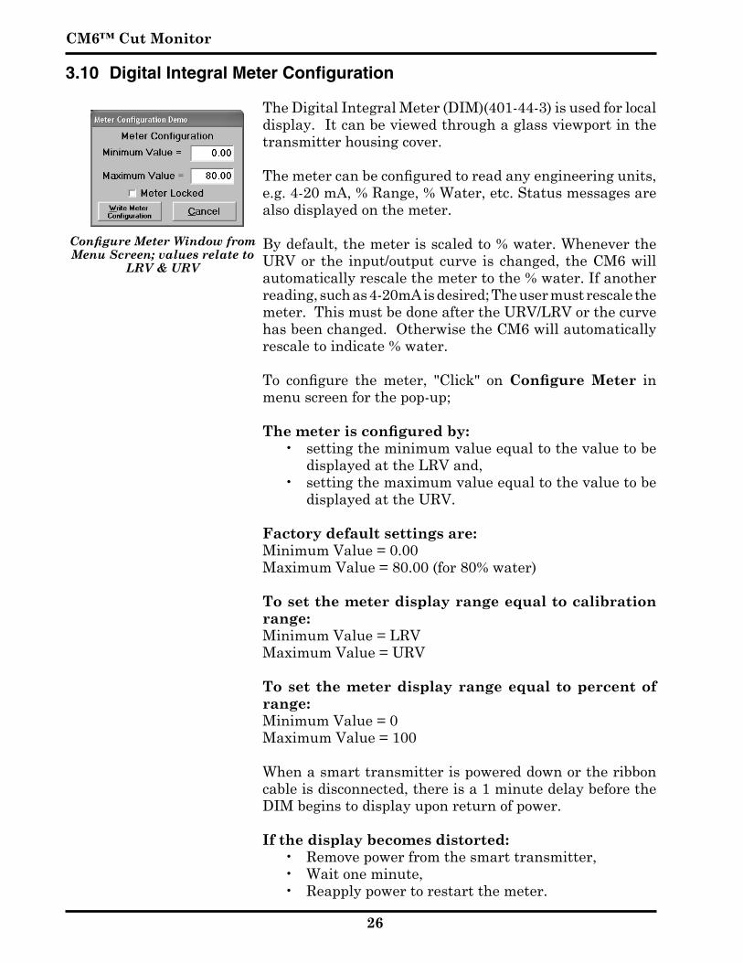
3.10 Digital Integral Meter Configuration
The Digital Integral Meter (DIM)(401-44-3) is used for local display.Itcanbe�iewedthroughaglass�iewportinthetransmitterhousingco�er.
The meter can be configured to read any engineering units, e.g.4-20mA,%Range,%Water,etc.Statusmessagesarealsodisplayedonthemeter.
Bydefault,themeterisscaledto%water.Whene�ertheURV or the input/output curve is changed, the CM6 will automaticallyrescalethemetertothe%water.Ifanotherreading,suchas4-20mAisdesired;Theusermustrescalethemeter. This must be done after the URV/LRV or the curve hasbeenchanged.OtherwisetheCM6willautomaticallyrescaletoindicate%water.
To configure the meter, "Click" on Configure Meter inmenuscreenforthepop-up;
The meter is configured by: • settingtheminimum�alueequaltothe�aluetobe
displayedattheLRVand,• settingthemaximum�alueequaltothe�aluetobe
displayedattheURV.
Factory default settings are: MinimumValue=0.00 Maximum Value = 80.00 (for 80% water)
To set the meter display range equal to calibration range:
MinimumValue=LRV MaximumValue=URV
To set the meter display range equal to percent of range:
MinimumValue=0 MaximumValue=100
Whenasmarttransmitterispowereddownortheribboncableisdisconnected,thereisa1minutedelaybeforetheDIMbeginstodisplayuponreturnofpower.
If the display becomes distorted:• Remo�epowerfromthesmarttransmitter,• Waitoneminute,• Reapplypowertorestartthemeter.
Configure Meter Window from Menu Screen; values relate to
LRV & URV
Configuration & Calibration
��
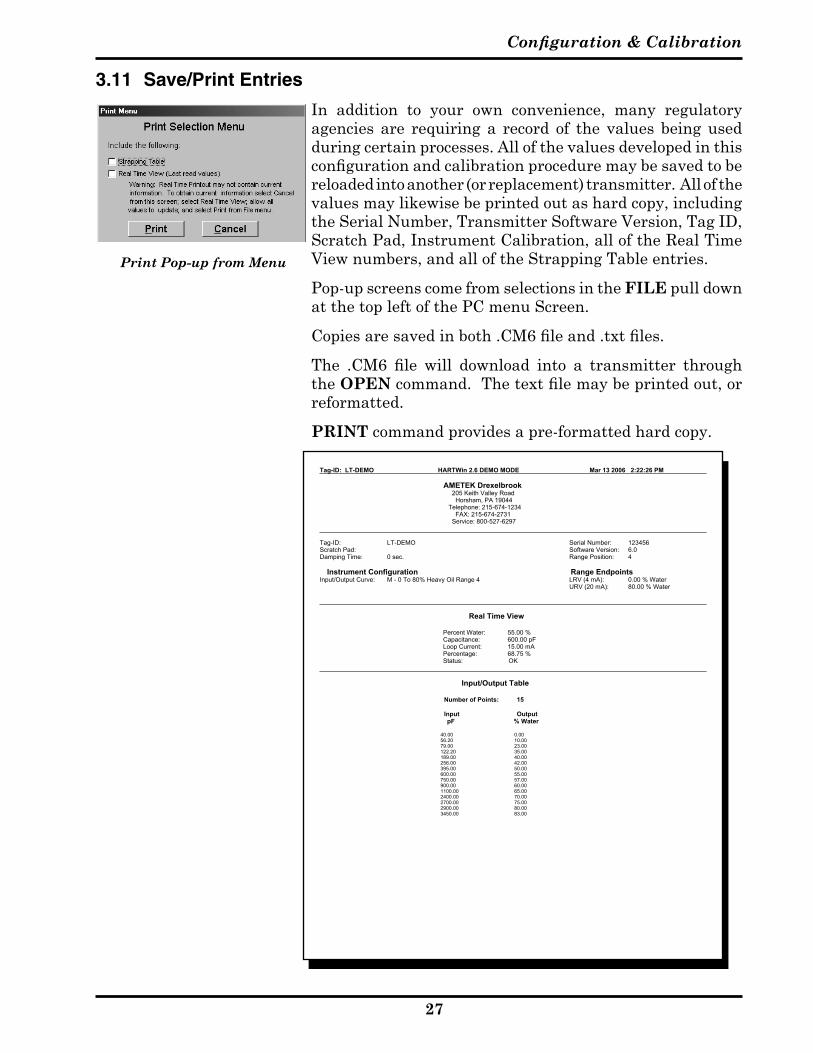
3.11 Save/Print Entries
In addition to your own con�enience, many regulatoryagencies are requiring a record of the �alues being usedduringcertainprocesses.Allofthe�aluesde�elopedinthisconfiguration and calibration procedure may be saved to be reloaded into another (or replacement) transmitter. All of the �aluesmaylikewisebeprintedoutashardcopy,includingthe Serial Number, Transmitter Software Version, Tag ID, ScratchPad,InstrumentCalibration,alloftheRealTimeViewnumbers,andalloftheStrappingTableentries.
Pop-upscreenscomefromselectionsintheFILEpulldownatthetopleftofthePCmenuScreen.
Copies are saved in both .CM6 file and .txt files.
The .CM6 file will download into a transmitter through theOPEN command. The text file may be printed out, or reformatted.
PRINTcommandpro�idesapre-formattedhardcopy.
Print Pop-up from Menu
Tag-ID: LT-DEMO HARTWin 2.6 DEMO MODE Mar 13 2006 2:22:26 PM
AMETEK Drexelbrook 205 Keith Valley Road Horsham, PA 19044 Telephone: 215-674-1234 FAX: 215-674-2731 Service: 800-527-6297
Tag-ID: LT-DEMO Serial Number: 123456Scratch Pad: DEMO CALIBRATION Software Version: 6.0Damping Time: 0 sec. Range Position: 4
Instrument Configuration Range EndpointsInput/Output Curve: M - 0 To 80% Heavy Oil Range 4 LRV (4 mA): 0.00 % Water
URV (20 mA): 80.00 % Water
Real Time View
Percent Water: 55.00 %Capacitance: 600.00 pFLoop Current: 15.00 mAPercentage: 68.75 %Status: OK
Input/Output Table
Number of Points: 15
Input OutputpF % Water
40.00 0.0056.20 10.0079.00 23.00122.20 35.00189.00 40.00256.00 42.00395.00 50.00600.00 55.00750.00 57.00900.00 60.001100.00 65.002400.00 70.002700.00 75.002900.00 80.003450.00 83.00

CM6™ Cut Monitor
��
3.12 Calibration & Configuration via 401-44-3 Display/Keypad
Lrng (Lower Range Value) See?
Edit
Up/Down
Enter
Up/Down
View LRVEnter
Edit 0 - 99900Enter
Enter
Enter
Up/Down
Urng (Upper Range Value) See?
Edit
Up/Down
Enter
Up/Down
View URVEnter
Edit 0 - 99900Enter
Enter
Enter
Up/Down
diAg(Diagnostic Menu)
Up/Down
Up/Down
donE(Leave Menu)
Up/Down
CFg.d(Configure Display) See?
Edit
Up/DownMin Value
Max Value
Enter Edit 0 - 99900
Edit 0 - 99900Enter
Up/Down
Return
Up/Down
Enter
Up/Down
Enter
Enter
Up/DownMin Value
Max Value
Enter View Min Value
View Max ValueEnter
Up/Down
Return
Up/Down
Up/Down
Enter
Enter
Enter
Enter Enter
Enter
I.AdJ(DAC Trims)Edit 3.5 - 4.5 Value =
4.0?Enter
No
Edit 19.0-21.0
Yes
Value =20.0?
Enter
Yes
No
dELy (Damping Time) See?
Edit
Up/Down
Enter
Up/Down
View DampingEnter
Edit 0 - 90Enter
Enter
Enter
Up/Down
Sr.Hr(Software Rev/Hardware Rev) S.S.HHEnter
Enter
Up/Down
CAP(Capacitance) View CapacitanceEnterEnter
Sc.PO(Scale Percent Out) See?
Edit
Up/Down
Enter
Up/Down
View %Out ScaleEnter
Edit 1.0 or 100.0Enter
Enter
Enter
C.CAL (Cut Cal) See?
Edit
Up/DownIndicated
Water
SampledWater
Enter Edit0 - 99900
Edit 0 - 99900Enter
Up/Down
Return
Enter
Up/Down
Enter
Enter
Up/DownIndicated
Water
SampledWater
EnterView Indicated
Water
View SampledWater
Enter
Up/Down
Return
Up/Down
Enter
Enter
Enter Enter
Up/Down EnterUp/Down Enter
Up/Down
Up/Down
Up/Down
Up/Down
Enter
Up/Down
L.FAC (Load Defaults) Sure?EnterUp/Down
DeviceRestarts
Enter
Up/Down
rEt (Return to Main Menu)
Up/Down
EnterExit Main Menu
Enter
Enter
PASS (Password Enable) See?
Edit
Up/Down
Enter
Up/Down
View On or OffEnter
Edit On or OffEnter
Enter
Enter
Up/Down
StrP(Cut Type) See?
Edit
Up/DownUp/Down
View Cut TypeEnter
Edit0-1% Light Oil (A)0-5% Light Oil (B)0-10% Light Oil (C)0-30% Light Oil (D)0-50% Light Oil (E)0-1% Heavy Oil (F)0-5% Heavy Oil (G)0-10% Heavy Oil (H)0-30% Heavy Oil (I)0-50% Heavy Oil (J)0-80% Heavy Oil (M)0-50% Heavy Oil (P)
Escape Menu
Enter
Enter
Enter
Enter
Continued on Next Page

Configuration & Calibration
��
3.12 Calibration & Configuration via 401-44-3 Display/Keypad (Continued)
Lrng (Lower Range Value) See?
Edit
Up/Down
Enter
Up/Down
View LRVEnter
Edit 0 - 99900Enter
Enter
Enter
Up/Down
Urng (Upper Range Value) See?
Edit
Up/Down
Enter
Up/Down
View URVEnter
Edit 0 - 99900Enter
Enter
Enter
Up/Down
diAg(Diagnostic Menu)
Up/Down
Up/Down
donE(Leave Menu)
Up/Down
CFg.d(Configure Display) See?
Edit
Up/DownMin Value
Max Value
Enter Edit 0 - 99900
Edit 0 - 99900Enter
Up/Down
Return
Up/Down
Enter
Up/Down
Enter
Enter
Up/DownMin Value
Max Value
Enter View Min Value
View Max ValueEnter
Up/Down
Return
Up/Down
Up/Down
Enter
Enter
Enter
Enter Enter
Enter
I.AdJ(DAC Trims)Edit 3.5 - 4.5 Value =
4.0?Enter
No
Edit 19.0-21.0
Yes
Value =20.0?
Enter
Yes
No
dELy (Damping Time) See?
Edit
Up/Down
Enter
Up/Down
View DampingEnter
Edit 0 - 90Enter
Enter
Enter
Up/Down
Sr.Hr(Software Rev/Hardware Rev) S.S.HHEnter
Enter
Up/Down
CAP(Capacitance) View CapacitanceEnterEnter
Sc.PO(Scale Percent Out) See?
Edit
Up/Down
Enter
Up/Down
View %Out ScaleEnter
Edit 1.0 or 100.0Enter
Enter
Enter
C.CAL (Cut Cal) See?
Edit
Up/DownIndicated
Water
SampledWater
Enter Edit0 - 99900
Edit 0 - 99900Enter
Up/Down
Return
Enter
Up/Down
Enter
Enter
Up/DownIndicated
Water
SampledWater
EnterView Indicated
Water
View SampledWater
Enter
Up/Down
Return
Up/Down
Enter
Enter
Enter Enter
Up/Down EnterUp/Down Enter
Up/Down
Up/Down
Up/Down
Up/Down
Enter
Up/Down
L.FAC (Load Defaults) Sure?EnterUp/Down
DeviceRestarts
Enter
Up/Down
rEt (Return to Main Menu)
Up/Down
EnterExit Main Menu
Enter
Enter
PASS (Password Enable) See?
Edit
Up/Down
Enter
Up/Down
View On or OffEnter
Edit On or OffEnter
Enter
Enter
Up/Down
StrP(Cut Type) See?
Edit
Up/DownUp/Down
View Cut TypeEnter
Edit0-1% Light Oil (A)0-5% Light Oil (B)0-10% Light Oil (C)0-30% Light Oil (D)0-50% Light Oil (E)0-1% Heavy Oil (F)0-5% Heavy Oil (G)0-10% Heavy Oil (H)0-30% Heavy Oil (I)0-50% Heavy Oil (J)0-80% Heavy Oil (M)0-50% Heavy Oil (P)
Escape Menu
Enter
Enter
Enter
Enter
Continued From Previous Page

Section 4

Specifications
��
Section 4: Specifications
Power Requirement17 to 30 vdc (12 vdc @ 20 mA)
Output4-20 mA
Measurement Range- Heavy and Light Oils0-1% water 0-5% water0-10% water 0-30% water0-50% water 0-80% water
Housing RatingNEMA 4X
Ambient Temperature-40° F to 158° F-40° C to 70° C
Accuracy±0.1% water for 1% and 5% ranges.±5% of span for 10,30, 50, and 80% ranges (at standard conditions)
Step ResponseLess than 1 second to 90% of final value when damping = 0 sec.
Damping Time Constant0 to 90 seconds, 1 second steps.
Repeatability±0.5% of span
Resolution0.2% span
Hysteresis0.2% span
Ambient Temp Error±0.01% span/°F
Process Temperature Error±0.02% Water/°F (uncompensated)
Spark Protection (4-20 mA output)10 Amperes
Spark Protection (Sensor)10 Amperes (Center Wire to Shield or Shield to ground)
CommunicationsHART® Protocol
Communications Load Resistance250 - 750 Ohms 30 vdc
Max. Load Resistance750 Ohms 30 vdc
Electronics- Two Wire Transmitter Sensing Element
ClassPerm-A-Seal
Model Number700-1202-001
Pressure1500 PSI @ 250°F500 PSI @ 450°F
Cote Shield Lengths (CSL)2”, 3.5”, 10”
Insertion Length (IL)Variable
Mountings¾” NPT StandardANSI and DIN flange, Tri-Clamp mountings available
Wetted Parts316 S.S. and PEEK (Poly Ether Ether Keytone)*
* PEEK is a high temperature thermoplastic with characteristics similar to TFE but with far better abrasion resistance. PEEK is compatible with the same materials as 316 SS; except for sulfuric acid, methyl ethyl ketone, concentrated phenol, or nitric acid. Consult the factory for questions on addition-al material compatibility.
The CM6 has been approved for the followings installations, integral and remote, when powered from Intrinsically Safe power supply.
Explosion Proof / Class I, Div 1, Groups A, B, C, D (Integral)Intrinsically Safe / Class I, II, III, Div 1, Groups A, B, C, D, E, F, GNon-Incendive / Class 1, Div 2, Groups A, B, C, D, IP66, Type 4XDust Ignition Proof / Class II, III, Div 1, Groups E, F, G
Class I, Zone 2: Ex nA IICClass I, Div 2, Groups A, B, C, & D;Class II, Div 2, Groups E, F, & G; Class IIIClass I, Zone 0: Ex ia IICClass I, Div 1, Groups A, B, C, and D;
Class II, Div 1, Groups E, F, & G; Class III
Hazzard Classification and Approval

Section 5

Normal Maintenance
��
Section 5: Normal Maintenance
5.1 Viewport Cleaning
The viewport (if supplied) is made of Borosilicate glass and canbecleanedwithanycommonglasscleaningproduct(e.g.:Windex™, Isopropyl alcohol, etc.) that is suitable for the Class and Division rating of the specific system installation.

Section 6

Drawings
��
Section 6: DrawingsCM3 Series Cut Monitor Installation
Figure 2-2Mounting DimensionsIntegral Electronics
1" through 6" Pipe Size
6.1 Mounting & Dimensional Drawings
1" through 6" PipeIntegral Electronics
CM6™ Cut Monitor
�6
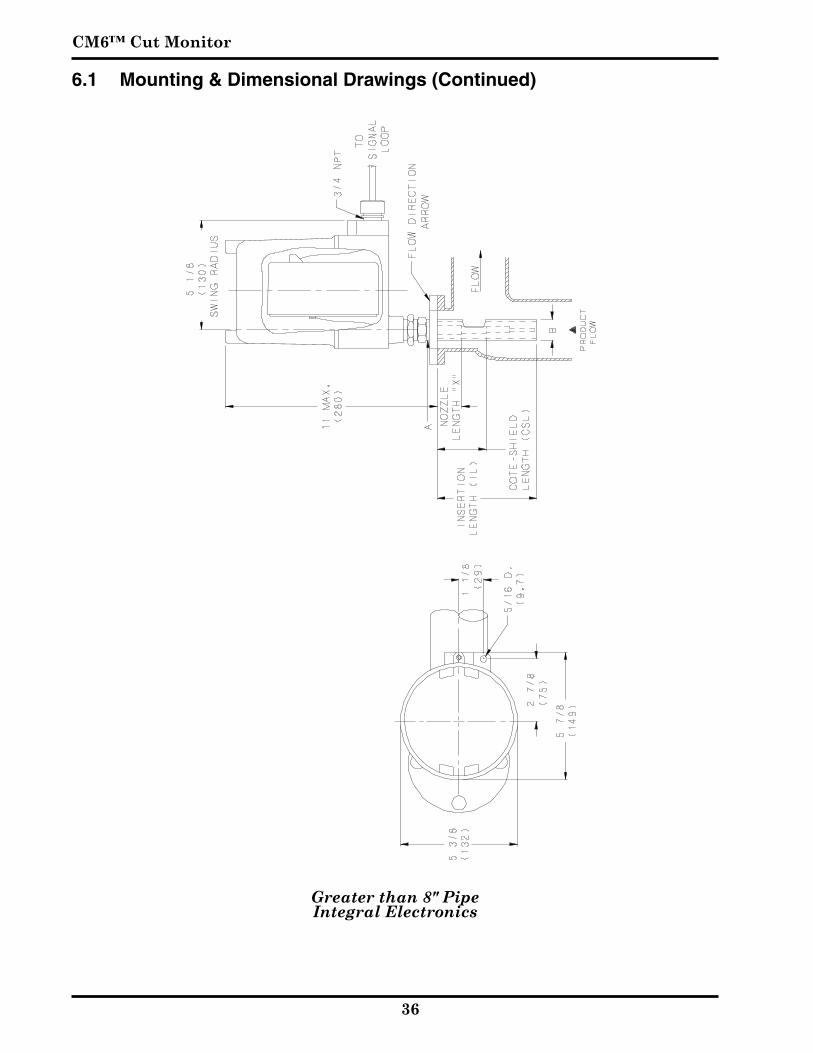
CM3 Series Cut Monitor Installation
Figure 2-3Mounting DimensionsIntegral Electronics
Greater than 8" Pipe Size
6.1 Mounting & Dimensional Drawings (Continued)
Greater than 8" PipeIntegral Electronics
Drawings
��
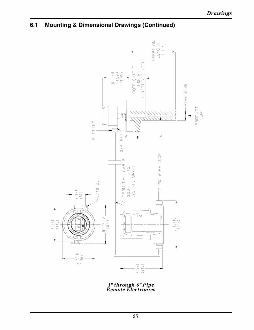
CM3 Series Cut Monitor Installation
Figure 2-4Mounting Dimensions
Remote Electronics1" through 6" Pipe Size
6.1 Mounting & Dimensional Drawings (Continued)
1" through 6" PipeRemote Electronics

CM6™ Cut Monitor
��
CM3 Series Cut Monitor Installation
Figure 2-5Mounting Dimensions
Remote ElectronicsGreater than 8" Pipe Size
Greater than 8" PipeRemote Electronics
6.1 Mounting & Dimensional Drawings (Continued)

Drawings
��
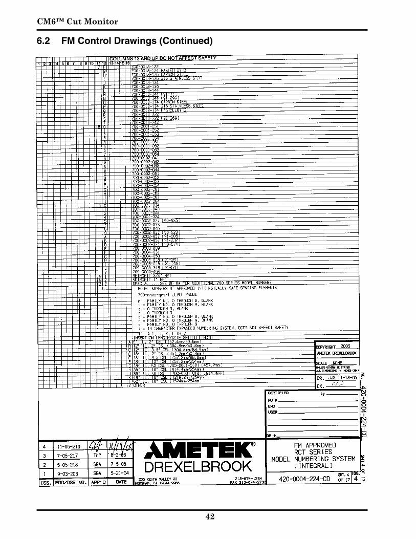
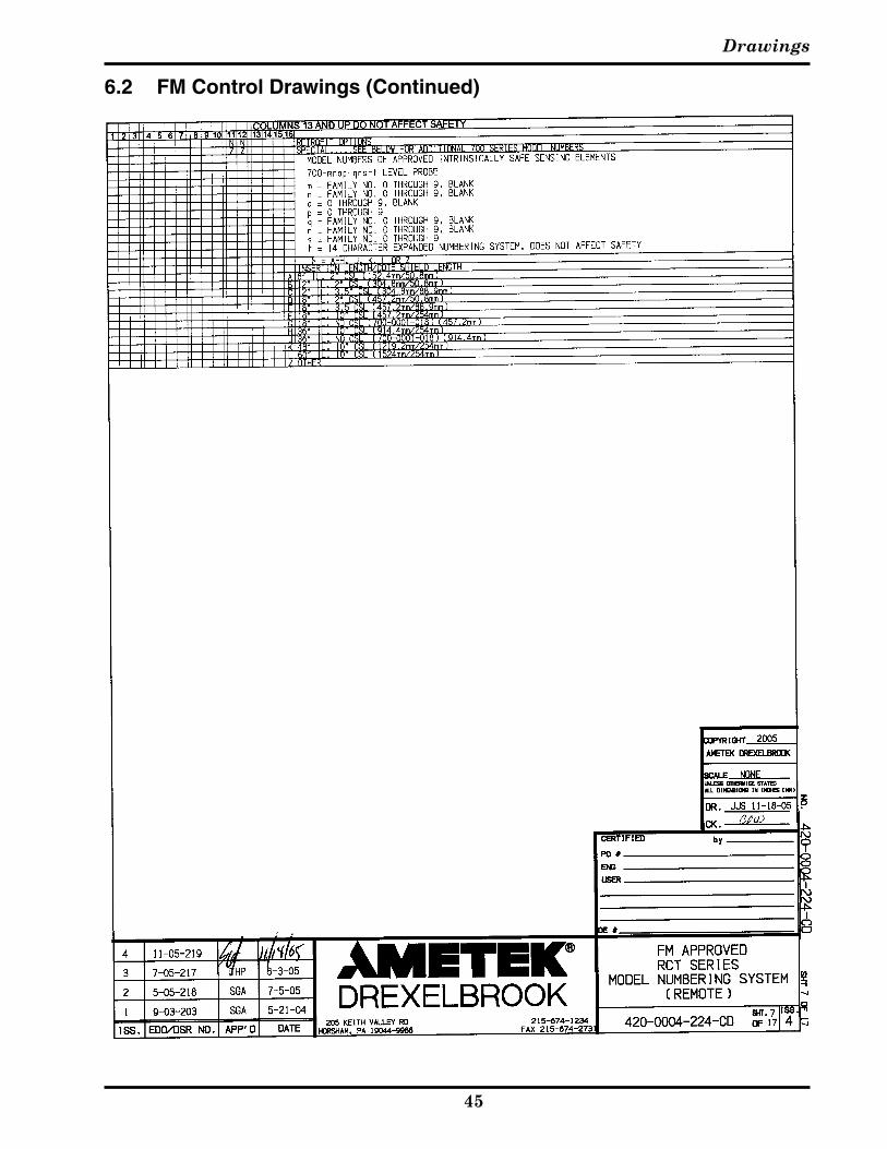
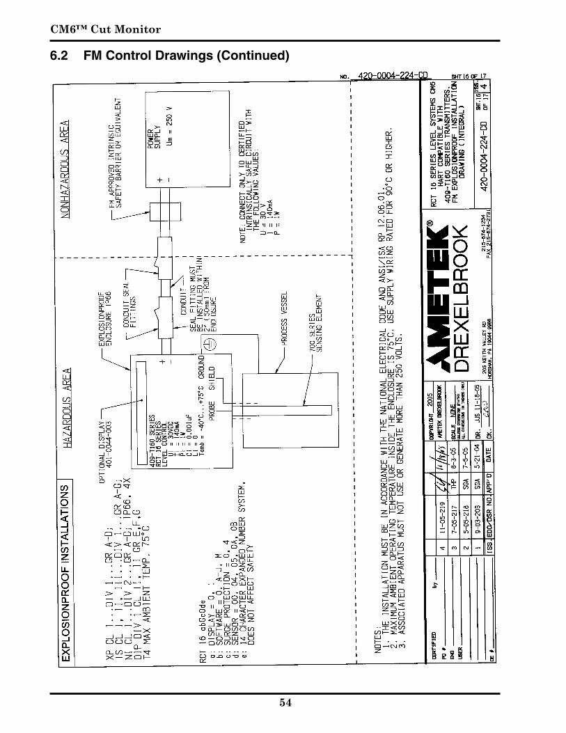
6.2 FM Control Drawings

CM6™ Cut Monitor
�0
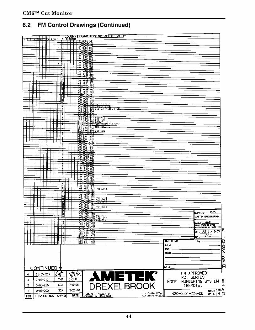
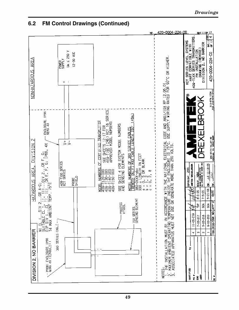
6.2 FM Control Drawings (Continued)

Drawings
��
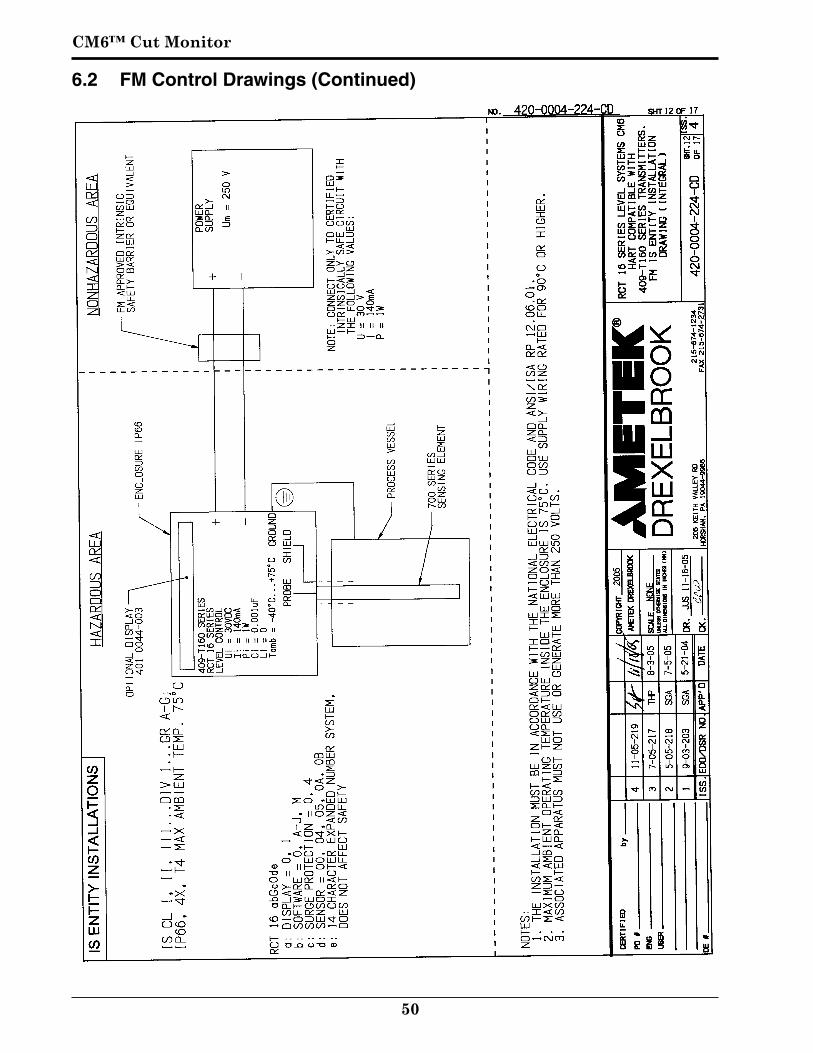
6.2 FM Control Drawings (Continued)
CM6™ Cut Monitor
��
6.2 FM Control Drawings (Continued)

Drawings
��
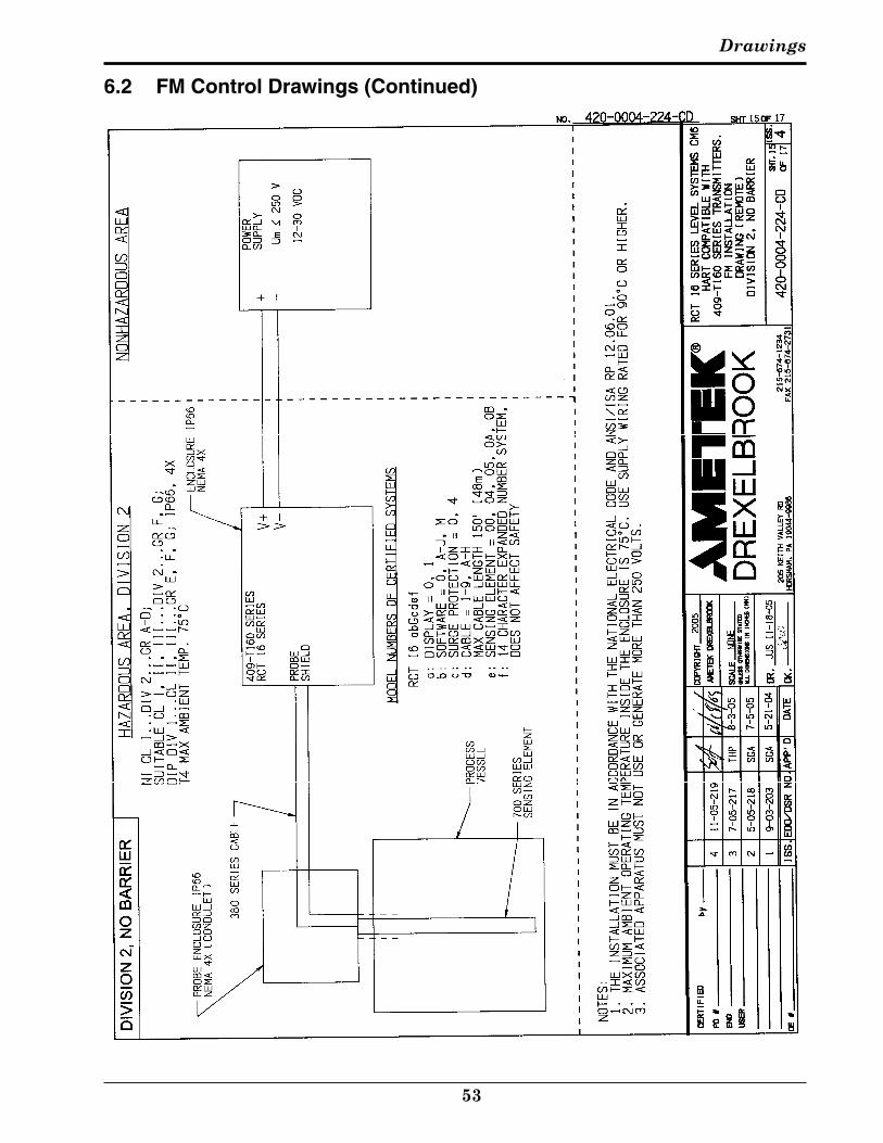
6.2 FM Control Drawings (Continued)
CM6™ Cut Monitor
��
6.2 FM Control Drawings (Continued)
Drawings
��
6.2 FM Control Drawings (Continued)

CM6™ Cut Monitor
�6
6.2 FM Control Drawings (Continued)

Drawings
��
6.2 FM Control Drawings (Continued)

CM6™ Cut Monitor
��
6.2 FM Control Drawings (Continued)
Drawings
��
6.2 FM Control Drawings (Continued)
CM6™ Cut Monitor
�0
6.2 FM Control Drawings (Continued)

Drawings
��
6.2 FM Control Drawings (Continued)

CM6™ Cut Monitor
��
6.2 FM Control Drawings (Continued)
Drawings
��
6.2 FM Control Drawings (Continued)
CM6™ Cut Monitor
��
6.2 FM Control Drawings (Continued)

Drawings
��
6.2 FM Control Drawings (Continued)
CM6™ Cut Monitor
�6
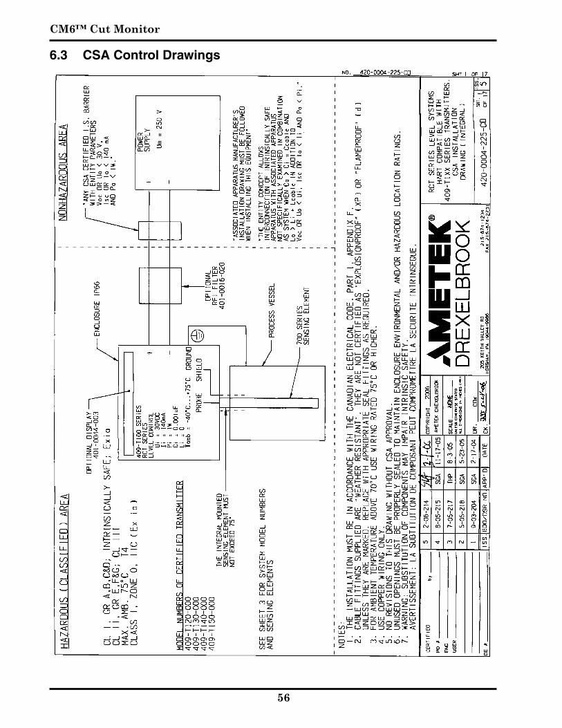
6.3 CSA Control Drawings
Drawings
��
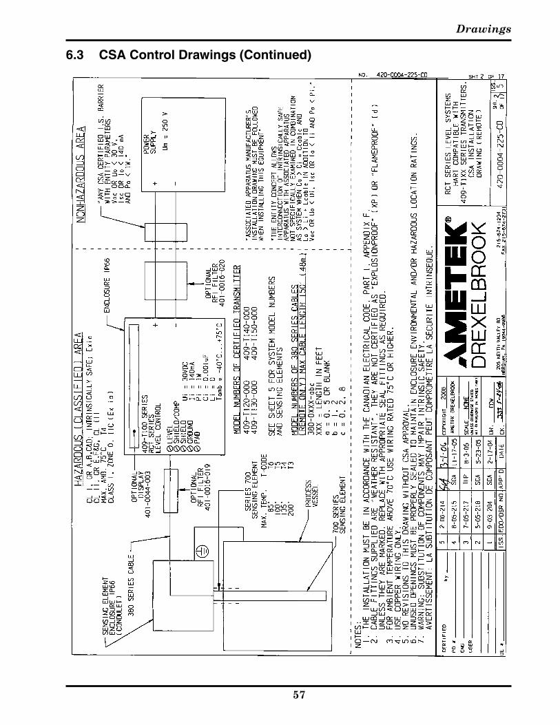
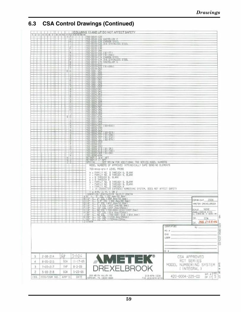
6.3 CSA Control Drawings (Continued)
CM6™ Cut Monitor
��
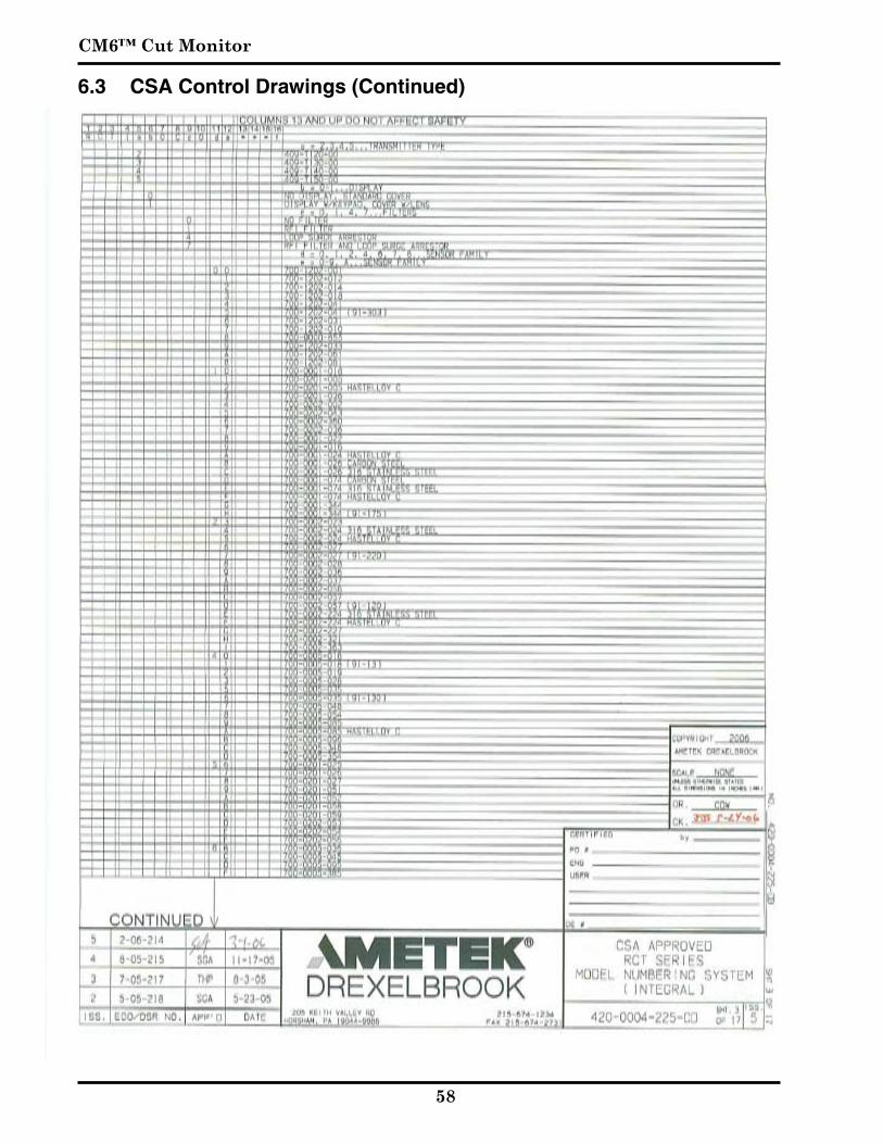
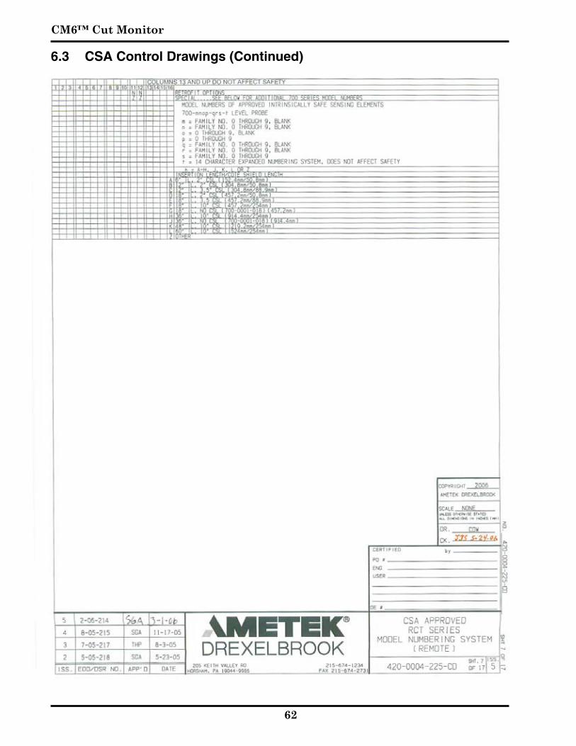
6.3 CSA Control Drawings (Continued)
Drawings
��
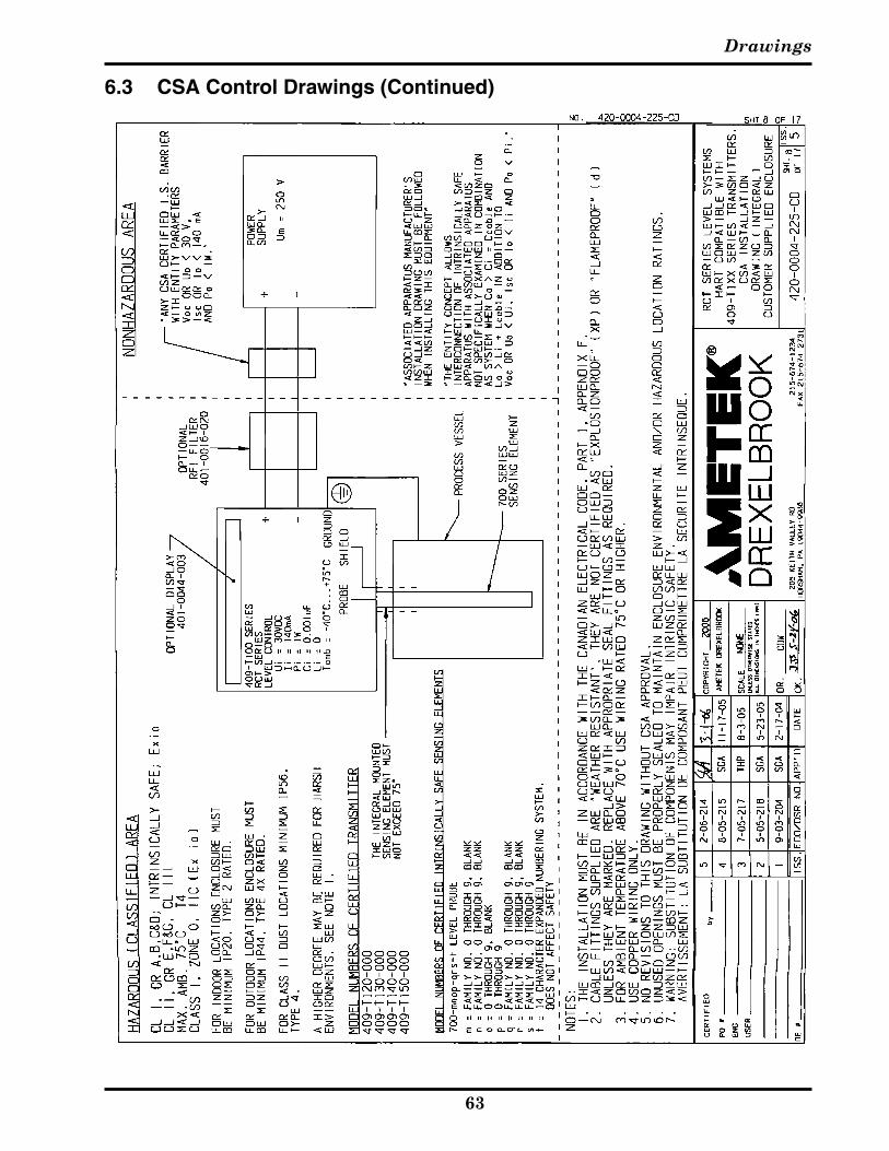
6.3 CSA Control Drawings (Continued)

CM6™ Cut Monitor
60
6.3 CSA Control Drawings (Continued)

Drawings
6�
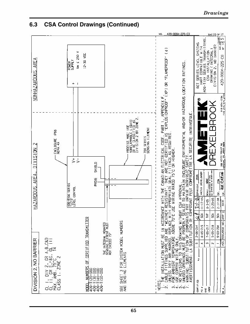
6.3 CSA Control Drawings (Continued)
CM6™ Cut Monitor
6�
6.3 CSA Control Drawings (Continued)
Drawings
6�
6.3 CSA Control Drawings (Continued)

CM6™ Cut Monitor
6�
6.3 CSA Control Drawings (Continued)
Drawings
6�
6.3 CSA Control Drawings (Continued)
CM6™ Cut Monitor
66
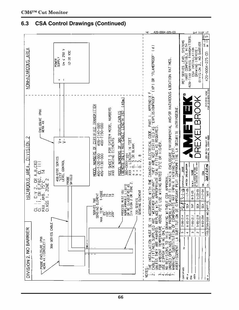
6.3 CSA Control Drawings (Continued)
Drawings
6�
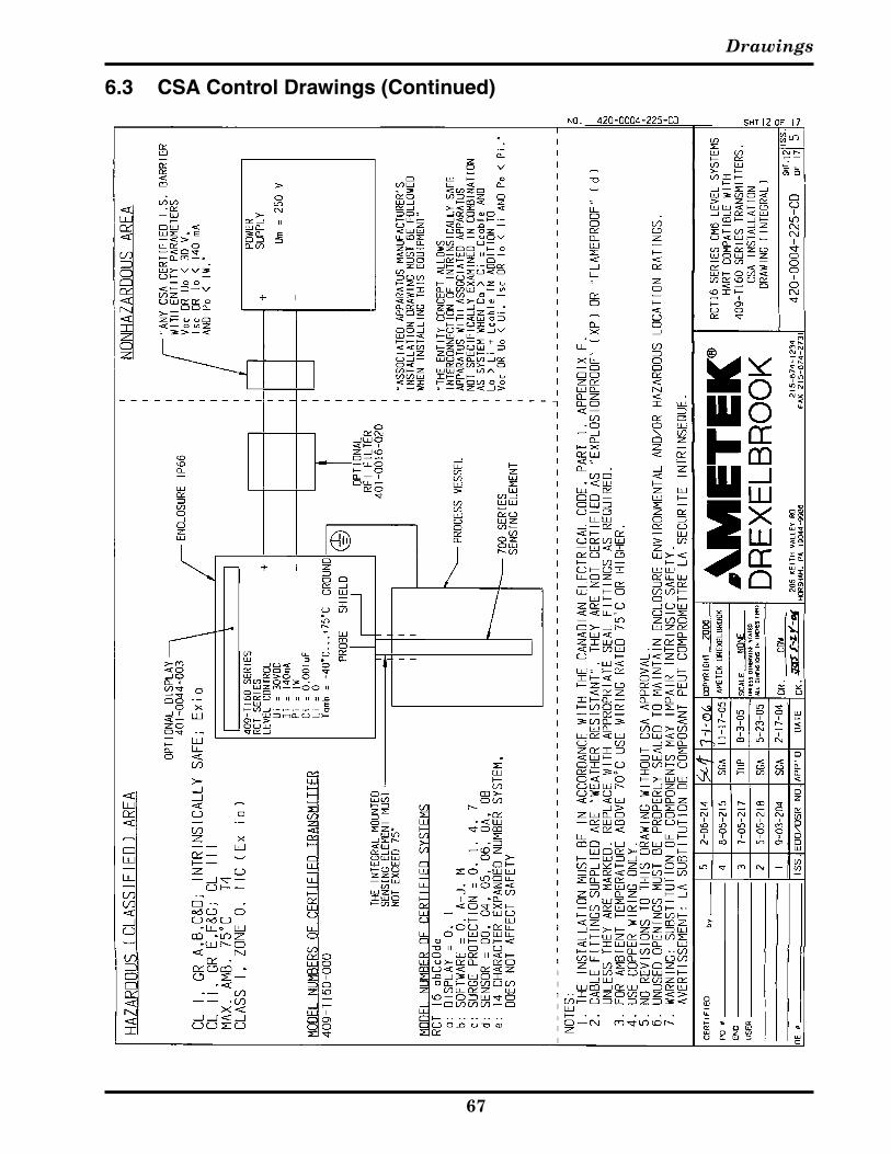
6.3 CSA Control Drawings (Continued)

CM6™ Cut Monitor
6�
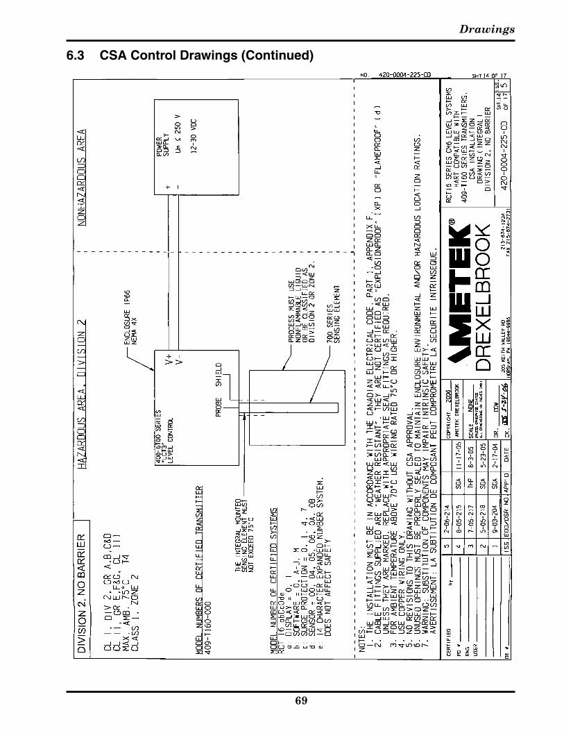
6.3 CSA Control Drawings (Continued)
Drawings
6�
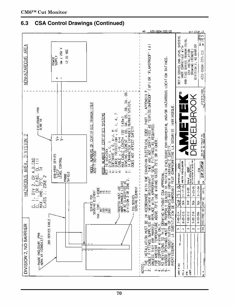
6.3 CSA Control Drawings (Continued)
CM6™ Cut Monitor
�0
6.3 CSA Control Drawings (Continued)
Drawings
��
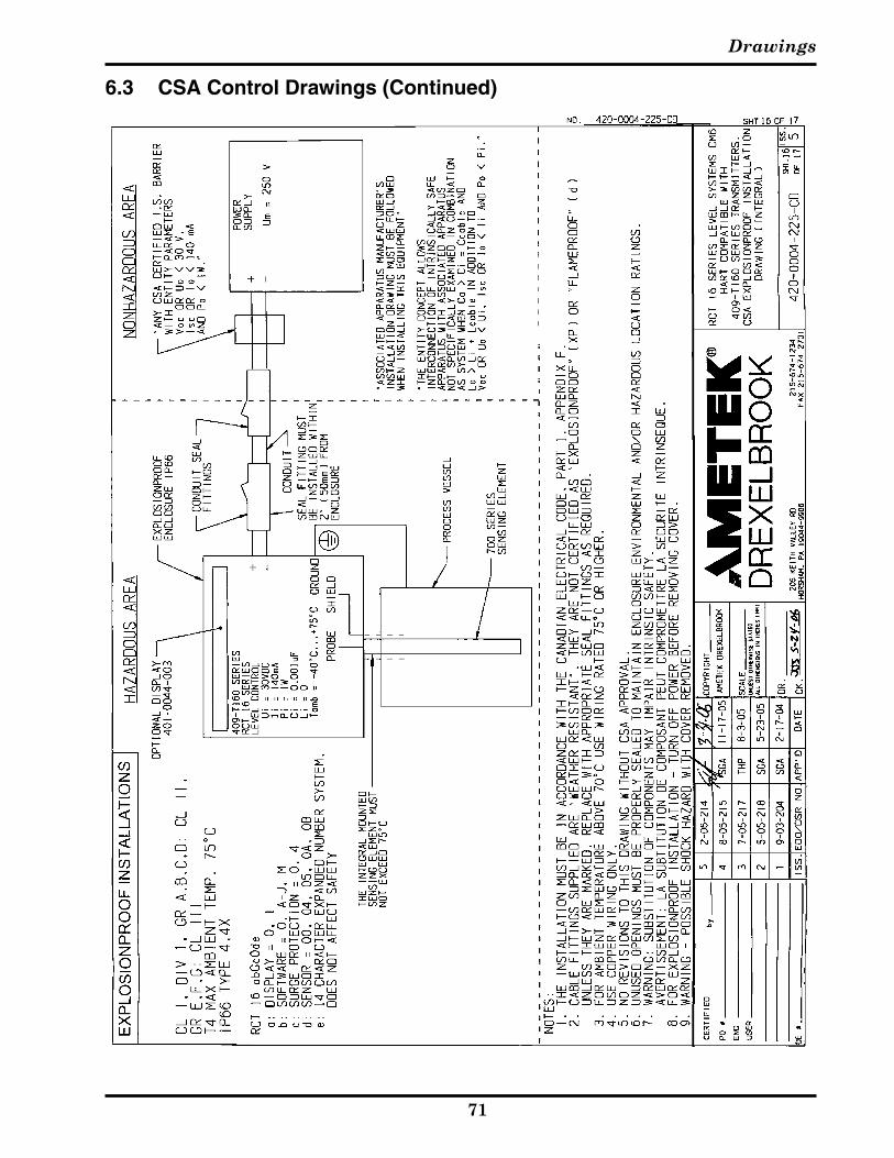
6.3 CSA Control Drawings (Continued)
CM6™ Cut Monitor
��
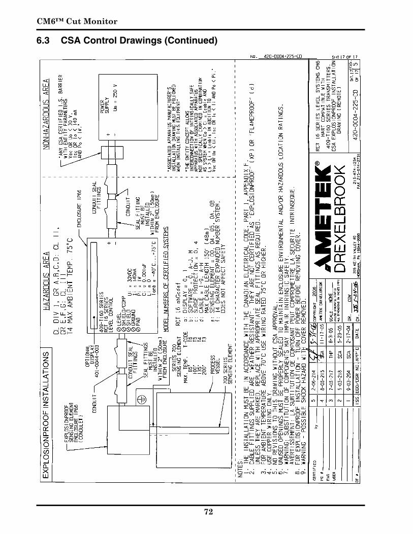
6.3 CSA Control Drawings (Continued)


Form 440-0001-001 3/1/2006
TERMS AND CONDITIONS OF SALEGENERAL: ALL ORDERS ARE SUBJECT TO THE FOLLOWING TERMS AND CONDITIONS. ANY ACCEPTANCE OF ANY OFFER OF BUYER FOR ANY GOODS OR SERVICES IS CONDITIONED UPON THESE TERMS AND CONDITIONS, AND SELLER OBJECTS TO ANY ADDITIONAL OR DIFFERENT TERMS PROPOSED BY BUYER IN ANY DOCUMENT, WHICH SHALL NOT BE BINDING UPON SELLER. No salesman or other party is authorized to bind the AMETEK DREXELBROOK Division of AMETEK, Inc. (hereinafter “Seller”) by any agreement, warranty, statement, promise, or understanding not herein expressed, and no modifications shall be binding on Seller unless the same are in writing and signed by an executive officer of Seller or his or her duly authorized representative. Verbal orders shall not be executed until written notification has been received and acknowledged by Seller.
QUOTATIONS: Written quotations are valid for thirty (30) days unless otherwise stated. Verbal quotations expire the same day they are made.
PRICES: All prices and terms are subject to change without notice. Buyer-requested changes to its order (“Orders”), including those affecting the identity, scope and delivery of the goods or services, must be documented in writing and are subject to Seller’s prior approval and adjustments in price, schedule and other affected terms and conditions. Orders requiring certified test data in excess of commercial requirements, are subject to a special charge.
ORDER ACCEPTANCE: All Orders are subject to final approval and acceptance by Seller at its office located at 205 Keith Valley Road, Horsham, Pennsylvania 19044.
TERMS OF PAYMENT: Seller’s standard terms of payment for Buyers who qualify for credit are net thirty (30) days from date of invoice. All invoices must be paid in United States dollars.
CREDIT: Seller reserves the right at any time to revoke any credit extended to Buyer or otherwise modify terms of payment if Buyer fails to pay for any shipments when due or if in Seller’s opinion there is a material adverse change in Buyer’s financial condition. Seller may, at its option, cancel any accepted Order if Buyer fails to pay any invoices when due.
DELIVERY: Shipments are F.O.B place of manufacture (“Shipping Point”) and the Buyer shall pay all freight, transportation, shipping, duties, fees, handling, insurance, storage, demurrage, or similar charges from Shipping Point. Delivery of goods to common carrier shall constitute delivery and passing of title to the Buyer, and all risk of loss or damage in transit shall be borne by Buyer. Any claims or losses for damage or destruction after such delivery shall be the responsibility of Buyer.
Seller reserves the right to make delivery in installments which shall be separately invoiced and paid for when due, without regard to subsequent deliveries. Delay in delivery of any installment shall not relieve Buyer of its obligation to accept remaining deliveries.
Acknowledged shipping dates are approximate only and based on prompt receipt of all necessary information from Buyer and Buyer’s compliance with terms of payment.
TAXES: All sales, excise and similar taxes which Seller may be required to pay or collect with respect to the goods and/or services covered by any Order, shall be for the account of the Buyer except as otherwise provided by law or unless specifically stated otherwise by Seller in writing.
TERMINATION AND HOLD ORDERS: No Order may be terminated by Buyer except upon written request by Buyer and approval by Seller, and if said request is approved by Seller, under the following conditions: (1) Buyer agrees to accept delivery of all of the units completed by Seller through the workday on which Seller receives the written termination request; (2) Buyer agrees to pay to Seller all direct costs and expenses applicable to the portion of the Order that is incomplete.
WARRANTY: A. Hardware: Seller warrants its goods against defects in materials and workmanship under normal use and service for one (1) year from the date of invoice. B. Software and Firmware: Unless otherwise specified, Seller warrants for a period of one (1) year from date of invoice that standard software or firmware, when used with Seller specified hardware, shall perform in accordance with Seller’s published specifications. Seller makes no representation or warranty, expressed or implied, that the operation of the software or firmware shall be uninterrupted or error-free, or that functions contained therein shall meet or satisfy the Buyer’s intended use or requirements. C. Services: Seller warrants that services, including engineering and custom application, whether provided on a fixed cost or time and material basis, shall be performed in accordance with generally accepted industry practices. D. Remedies: Seller’s liability under this section is restricted to replacing, repairing, or issuing credit (at Seller’s option) for any returned goods and only under the following conditions: (1) Seller must be promptly notified, in writing, as soon as possible after the defects have been noted by the Buyer, but not later than (1) year from date of invoice from Seller; (2) The defective goods are to be returned to the place of manufacture, shipping charges prepaid by the Buyer; (3) Seller’s inspection shall disclose to its satisfaction that the goods were defective in materials or workmanship at the time of shipment; (4) Any warranty service (consisting of time, travel and expenses related to such services) performed other than at Seller’s factory, shall be at Buyer’s expense. E.Repaired/Reconditioned Goods: As to out-of-warranty goods which Seller has repaired or reconditioned, Seller warrants for a period of sixty (60) days from date of its invoice only new components replaced in the most recent repair/reconditioning. F. Returns and Adjustments: No goods may be returned unless authorized in advance by Seller and then only upon such conditions to which Seller may agree. Buyer must obtain an RMA (Return Material Authorization) number from Seller prior to any return shipment and such RMA number must appear on the shipping label and packing slip. Buyer shall be responsible for the returned goods until such time as Seller receives the same at its plant and for all charges for packing, inspection, shipping, transportation, or insurance associated with returned goods. In the event that credit for returned goods is granted, it shall be at the lesser of the then current prices or the original purchase price. Claims for shortage or incorrect material must be made within five (5) days after receipt of shipment.
ALL OTHER WARRANTIES, FOR ANY OF SELLER’S GOODS OR SERVICES, WHETHER ORAL, WRITTEN, EXPRESS, IMPLIED, STATUTORY OR OTHERWISE, INCLUDING WITHOUT LIMITATION ANY IMPLIED WARRANTY OF MERCHANTABILITY OR FITNESS FOR PURPOSE ARE EXCLUDED.
INTELLECTUAL PROPERTY: Seller’s sale of goods or provision of related documentation or other materials to Buyer shall not transfer any intellectual property rights to Buyer unless Seller specifically agrees to do so in writing. Seller shall retain ownership of all applicable patents, trademarks, copyrights and other intellectual property rights. Buyer shall not use, copy or transfer any such items in violation of Seller’s intellectual property rights or applicable law, or for any purposes other than that for which the items were furnished.
Seller shall defend any lawsuit brought against the Buyer based on a claim that the design or construction of the goods sold hereunder by Seller infringe any United States or Canadian Patent, Copyright or Mask Work Registration, provided that Buyer promptly notifies Seller of such claim in writing and further provided that, at Seller’s expense, (1) Buyer gives Seller the sole right to defend or control the defense of the suit or proceeding, including settlement, and (2) Buyer provides all necessary information and assistance for that defense. In the event of a charge of infringement, Seller’s obligation under the agreement shall be fulfilled if Seller, at its option and expense, either (i) settles such claim; (ii) procures for Buyer the right to continue using such goods; (iii) replaces or modifies goods to avoid infringement; or (iv) accepts the return of any infringing goods and refunds their purchase price; or (iv) defends against such claim.
If Buyer furnishes specifications or designs to Seller, the obligations of Seller set forth above shall not apply to goods made by Seller using such specifications or designs, and Buyer shall defend, indemnify and hold Seller harmless against any third party claims for infringement which arise out of Seller’s use of specifications or designs furnished by Buyer.
SOFTWARE LICENSE: If goods purchased hereunder include software (“Software”), Buyer may use the Software only as part of the goods. Buyer may not use, copy, or transfer any of the Software except as may be permitted under the applicable License Agreement provided with the goods. Buyer’s right to use, copy or transfer the Software shall terminate upon termination of Buyer’s right to use the goods.
PACKAGING/WEIGHTS AND DIMENSIONS: Buyer specified packing or marking may be subject to additional charges not otherwise included in the price of the goods. Published weights and dimensions are estimates or approximate only and are not warranted.
FORCE MAJEURE: Seller shall not be responsible for delays in delivery or any failure to deliver due to causes beyond Seller’s control, including but not limited to the following items: acts of God, war, terrorism, mobilization, civil commotion, riots, embargoes, domestic or foreign governmental regulations or orders, governmental priorities, port congestion, acts of the Buyer, its agents or employees, fires, floods, strikes, lockouts and other labor difficulties, shortages of or inability to obtain shipping space or transportation, inability to secure fuel, supplies or power at current prices or on account of shortages thereof, or due to limitations imposed by the extent of availability of Seller’s normal manufacturing facilities.
If a delay excused per the above extends for more than ninety (90) days and the parties have not agreed upon a revised basis for continuing providing the goods or services at the end of the delay, including adjustment of the price, then Buyer, upon thirty (30) days’ prior written notice to Seller may terminate the Order with respect to the unexecuted portion of the goods or services, whereupon Buyer shall promptly pay Seller its reasonable termination charges upon submission of Seller’s invoices thereof.
LIMITATION OF LIABILITY: Seller’s liability for any claim of any kind, except infringement of intellectual property rights, shall not exceed the purchase price of any goods or services which give rise to the claim. SELLER SHALL IN NO EVENT BE LIABLE FOR BUYER’S MANUFACTURING COSTS, LOST PROFITS, LOSS OF USE OF THE GOODS OR SERVICES, COST OF CAPITAL, COST OF SUBSTITUTE GOODS, FACILITIES, SERVICES OR REPLACEMENT POWER, DOWNTIME COSTS, CLAIMS OF BUYER’S CUSTOMERS FOR DAMAGES, OR OTHER SPECIAL, PROXIMATE, INCIDENTAL, INDIRECT, EXEMPLARY OR CONSEQUENTIAL DAMAGES. Any action against Seller must be brought within eighteen (18) months after the cause of action accrues. These disclaimers and limitations of liability shall apply regardless of the form of action, whether in contract, tort or otherwise, and further shall extend to the benefit of Seller’s vendors, appointed distributors and other authorized resellers as third-party beneficiaries.
PROHIBITION FOR HAZARDOUS USE: Goods sold hereunder generally are not intended for application in and shall not be used by Buyer in the construction or operation of a nuclear installation or in connection with the use or handling of nuclear material, or for any hazardous activity or critical application, where failure of a single component could cause substantial harm to persons or property, unless the goods have been specifically approved for such a use or application. Seller disclaims all liability for any loss or damage resulting from such unauthorized use and Buyer shall defend, indemnify and hold harmless the Seller against any such liability, whether as a result of breach of contract, warranty, tort (regardless of the degree of fault or negligence), strict liability or otherwise.
EXPORT CONTROL: Buyer shall comply with all export control laws and regulations of the United States, and all sales hereunder are subject to those laws and regulations. Seller shall not be named as shipper or exporter of record for any goods sold hereunder unless specifically agreed to in writing by Seller. At Seller’s request, Buyer shall furnish Seller with end-use and end-user information to determine export license applicability. Buyer warrants, in accordance with U.S. Export Law, that goods sold hereunder shall not be destined for facilities or activities involving nuclear, chemical or biological weapons, or related missile delivery systems in named prohibited regions or countries.
GOVERNING LAW: Seller intends to comply with all laws applicable to its performance under any order. All matters relating to interpretation and effect of these terms and any authorized changes, modifications or amendments thereto shall be governed by the laws of the Commonwealth of Pennsylvania. No government contract regulations or clauses shall apply to the goods or services, this agreement, or act to bind Seller unless specifically agreed to by Seller in writing.
NON-WAIVER BY SELLER: Waiver by Seller of a breach of any of these terms and conditions shall not be construed as a waiver of any other breach.
SEVERABILITY AND ENTIRE AGREEMENT: If any provision of these terms and conditions is unenforceable, the remaining terms shall nonetheless continue in full force and effect. This writing, together with any other terms and conditions Seller specifically agrees to in writing, constitutes the entire terms and conditions of sale between Buyer and Seller and supercedes any and all prior discussions, and negotiations on its subject matter.


205 Keith Valley Road, Horsham, PA 19044 U.S. and Canada: 1-800-553-909224-Hour Service: 1-800-527-6297International: +1 215-674-1234Fax: +1 215-674-2731E-mail: [email protected] Website: www.drexelbrook.com
An ISO 9001 Certified Company