installation and maintenance manual im818 - daikin...
TRANSCRIPT
IM 818 Page 1
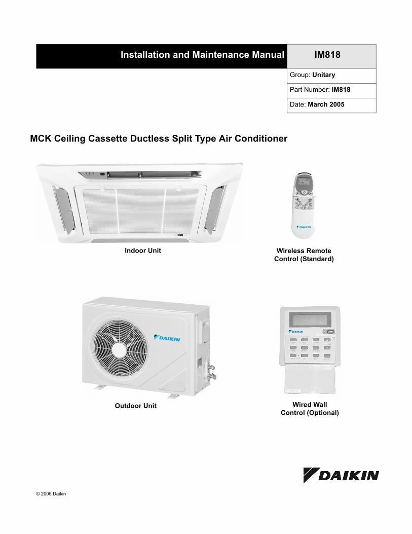
MCK Ceiling Cassette Ductless Split Type Air Conditioner
Installation and Maintenance Manual IM818
Group: Unitary
Part Number: IM818
Date: March 2005
© 2005 Daikin
Indoor Unit Wireless RemoteControl (Standard)
Outdoor Unit Wired WallControl (Optional)

Page 2 IM 818
Table of ContentsModel Numbers . . . . . . . . . . . . . . . . . . . . . . . . . . . . . 2Cooling Only . . . . . . . . . . . . . . . . . . . . . . . . . . . . . . . . 2Cooling/Heat Pump . . . . . . . . . . . . . . . . . . . . . . . . . . 2General Information . . . . . . . . . . . . . . . . . . . . . . . . . 3Safety Precautions . . . . . . . . . . . . . . . . . . . . . . . . . . . 3Unit Dimensions . . . . . . . . . . . . . . . . . . . . . . . . . . . . 4Indoor Units . . . . . . . . . . . . . . . . . . . . . . . . . . . . . . . . . 4Outdoor Units . . . . . . . . . . . . . . . . . . . . . . . . . . . . . . . 4Installation Guidelines . . . . . . . . . . . . . . . . . . . . . . . 5Installation Diagram. . . . . . . . . . . . . . . . . . . . . . . . . . . 5Installation of Outdoor Unit . . . . . . . . . . . . . . . . . . . . . 5Installation of the Indoor Unit. . . . . . . . . . . . . . . . . . . . 5Drain Piping. . . . . . . . . . . . . . . . . . . . . . . . . . . . . . . . . 6Drain Test . . . . . . . . . . . . . . . . . . . . . . . . . . . . . . . . . . 6Condensate Pump. . . . . . . . . . . . . . . . . . . . . . . . . . . . 6Water Level Switch . . . . . . . . . . . . . . . . . . . . . . . . . . . 6Front Panel Installation . . . . . . . . . . . . . . . . . . . . . . . . 6Air Intake Grille Installation . . . . . . . . . . . . . . . . . . . . . 7Refrigerant Tubing . . . . . . . . . . . . . . . . . . . . . . . . . . 8Tubing Length & Elevation . . . . . . . . . . . . . . . . . . . . . 8Tubing Preparation . . . . . . . . . . . . . . . . . . . . . . . . . . . 8Tubing Connection To Units . . . . . . . . . . . . . . . . . . . . 8Electrical Connections . . . . . . . . . . . . . . . . . . . . . . . 9Wiring Diagrams . . . . . . . . . . . . . . . . . . . . . . . . . . . 10
Evacuating and Charging. . . . . . . . . . . . . . . . . . . . 17Evacuating the tubing and the indoor unit. . . . . . . . . 17Additional charge . . . . . . . . . . . . . . . . . . . . . . . . . . . 17Charge operation . . . . . . . . . . . . . . . . . . . . . . . . . . . 17Remote Controller Operation Guide . . . . . . . . . . . 18Wired Wall Control (Optional) . . . . . . . . . . . . . . . . 19Special Features . . . . . . . . . . . . . . . . . . . . . . . . . . 20Dry mode . . . . . . . . . . . . . . . . . . . . . . . . . . . . . . . . . 20Heat mode (heat pump only) . . . . . . . . . . . . . . . . . . 20Overheating protection (heat pump only) . . . . . . . . . 20Frost prevention . . . . . . . . . . . . . . . . . . . . . . . . . . . . 20Fan speed and rated cooling capacity . . . . . . . . . . . 20Operating Conditions . . . . . . . . . . . . . . . . . . . . . . 20Cooling . . . . . . . . . . . . . . . . . . . . . . . . . . . . . . . . . . . 20Overall Checking . . . . . . . . . . . . . . . . . . . . . . . . . . . 20Unit Indicator Lights . . . . . . . . . . . . . . . . . . . . . . . . 21IR signal receiver . . . . . . . . . . . . . . . . . . . . . . . . . . . 21Wireless Remote Control . . . . . . . . . . . . . . . . . . . . . 21Mode and Diagnostic Chart . . . . . . . . . . . . . . . . . . . 21Startup After Extended Shutdown . . . . . . . . . . . . 22Troubleshooting . . . . . . . . . . . . . . . . . . . . . . . . . . . 22Service and Maintenance . . . . . . . . . . . . . . . . . . . 23
Model NumbersCooling Only
Cooling/Heat Pump
Indoor Unit Outdoor Unit Nominal Cooling - BTUHMCK20A MLC20B 21,000MCK25A MLC25B 25,000MCK30A MLC30C 30,000MCK40A MLC40C 40,000MCK50A MLC50C 50,000
Indoor Unit Outdoor Unit Nominal Cooling - BTUH Nominal Heating - BTUHMCK20AR MLC20BR 20,000 20,000MCK25AR MLC25BR 25,000 25,000MCK30AR MLC30CR 30,000 31,000MCK40AR MLC40CR 40,000 41,000MCK50AR MLC50CR 48,000 50,000
IM 818 Page 3
General InformationThis manual provides the installation procedures so your air conditioner unit operates properly and pro-vides you the service it was designed to provide.Special adjustment may be necessary to suit local requirements. Before using your air conditioner, please read this instruction manual carefully and keep it for future reference.
Safety PrecautionsBefore installing the air conditioner unit, please read the fol-lowing safety precautions carefully.
.
WARNING
• The installer must determine and follow all applicablecodes and regulations. This equipment presents hazardsof electricity, rotating parts, sharp edges, heat andweight. Failure to read and follow these instructionscan cause property damage, equipment damage, severepersonal injury or death. This equipment must beinstalled by experienced, trained personnel only.
• Do not allow flammable fumes near unit or areas shar-ing ventilation.
• Installation and maintenance must be performed byqualified persons who are familiar with local code andregulation, and experienced with this type of appliance.
• All field wiring must be done in accordance withindustry standards and local codes.
• Inspect the unit nameplate to be certain the voltage isthe same as the voltage that will be delivered to theunit. Improper electrical wiring can cause propertydamage, sever personal energy or death.
• The unit must be GROUNDED.
• Make sure wiring does not touch refrigerant piping,compressor, or any moving parts of the fan motors.
• Confirm that the power supply is switched OFF beforeinstalling or servicing the unit.
WARNING
Hazardous Voltage!
Disconnect all electrical power including remotedisconnects before servicing. Failure to disconnectpower before servicing can cause severe personalinjury or death.
CAUTION
Use copper conductors only. Unit terminals are notdesigned to accept other types of conductors. Failure todo so can cause damage to the equipment.
CAUTION
• Do not install in a laundry room. Humidity and laundrychemicals can corrode unit components.
• Do not install the unit where leakage of flammable gasmay occur. If gas leaks and accumulates around theunit, it can cause a fire.
• Connect drainage piping properly. If drainage piping isnot connected properly, water leakage can cause prop-erty damage.
• Do not overcharge the unit. This unit is factory pre-charged. Overcharge will cause over-current or damage to the compressor.
• Keep panel closed. Unsecured panels will cause theunit to operate noisily.
NOTICE
This product was carefully packed and thoroughlyinspected before leaving the factory. Responsibility forits safe delivery was assumed by the carrier uponacceptance of the shipment. Claims for loss or damagesustained in transit must therefore be made upon thecarrier, as follows:VISIBLE LOSS OR DAMAGEAny external evidence of loss or damage must be notedon the freight bill or carrier’s receipt, and signed by thecarrier’s agent. Failure to adequately describe suchexternal evidence of loss or damage may result in thecarrie’s refusing to honor a damaged claim. The formrequired to file such a claim will be supplied by thecarrier.CONCEALED LOSS OR DAMAGEConcealed loss or damage means loss or damagewhich does not become apparent until the product hasbeen unpacked. The contents may be damaged intransit due to rough handling even though the cartonmay not show external damages. When the damage isdiscovered upon unpacking, make a written request forinspection by the carrier’s agent within fifteen (15)days of the delivery date. File a claim with the carriersince such damage is the carrier’s responsibility.

Page 4 IM 818
Unit DimensionsIndoor UnitModel: MCK20, 25, 30, 40, 50 A/AR
Outdoor UnitModel: MLC20 & 25B/BR, MLC30, 40 & 50C/CR
Note: See Figure 3 For More Detail
32 1/4”
32 1/4”
14 3/4”
13 3/4”
36 5/8”
36 5/8”
Front Panel
Frame
Frame andFront Panel
Model MLC 20 & 25 B/BR 30, 40 & 50C/CRA 16" 19 1/4"B 33" 40 1/2"C 25 1/2" 33 1/2"D 2 1/4" 3 1/2"E 13 1/4" 15 3/4"F 23 1/4" 29 3/8"G 4 7/8" 5 1/2"H 5/8" 3/4"J 3/4" 1"K 2" 2"
E
D
B
F
A
C
G
J
H
K
Electrical AccessPanel w/ 7/8” Knockout
RefrigerantPiping Connections
IM 818 Page 5
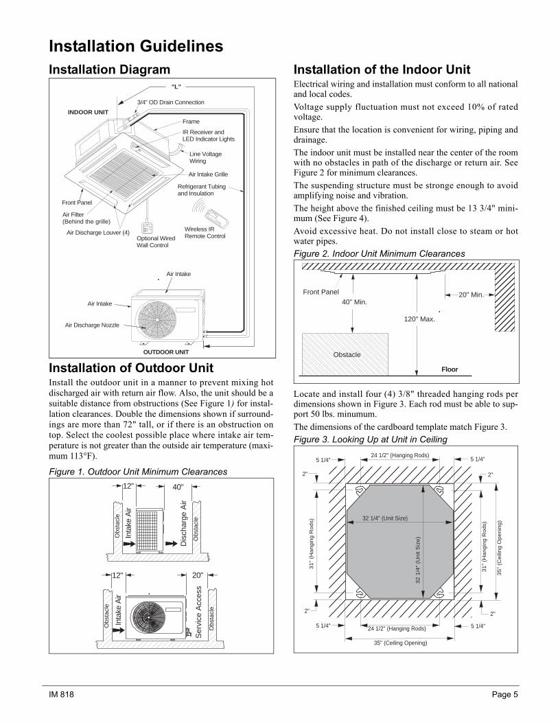
Installation GuidelinesInstallation Diagram
Installation of Outdoor UnitInstall the outdoor unit in a manner to prevent mixing hotdischarged air with return air flow. Also, the unit should be asuitable distance from obstructions (See Figure 1) for instal-lation clearances. Double the dimensions shown if surround-ings are more than 72" tall, or if there is an obstruction ontop. Select the coolest possible place where intake air tem-perature is not greater than the outside air temperature (maxi-mum 113°F).
Figure 1. Outdoor Unit Minimum Clearances
Installation of the Indoor UnitElectrical wiring and installation must conform to all nationaland local codes.Voltage supply fluctuation must not exceed 10% of ratedvoltage.Ensure that the location is convenient for wiring, piping anddrainage.The indoor unit must be installed near the center of the roomwith no obstacles in path of the discharge or return air. SeeFigure 2 for minimum clearances.The suspending structure must be stronge enough to avoidamplifying noise and vibration.The height above the finished ceiling must be 13 3/4" mini-mum (See Figure 4).Avoid excessive heat. Do not install close to steam or hotwater pipes.Figure 2. Indoor Unit Minimum Clearances
Locate and install four (4) 3/8" threaded hanging rods perdimensions shown in Figure 3. Each rod must be able to sup-port 50 lbs. minumum.The dimensions of the cardboard template match Figure 3.Figure 3. Looking Up at Unit in Ceiling
Air Intake
Air Discharge Nozzle
Air Intake
OUTDOOR UNIT
INDOOR UNIT
Wireless IRRemote Control
Front Panel
Air Filter(Behind the grille)
Air Discharge Louver (4)
3/4" OD Drain Connection
IR Receiver andLED Indicator Lights
Air Intake Grille
Refrigerant Tubingand Insulation
Frame
Line VoltageWiring
"L"
Optional WiredWall Control
12" 40"
12" 20"
Inta
ke A
ir
Dis
char
ge A
ir
Ser
vice
Acc
ess
Inta
ke A
ir
Obs
tacl
e
Obs
tacl
e
Obs
tacl
e
Obs
tacl
e
Obstacle
40" Min.
120" Max.
20" Min.
Floor
Front Panel
24 1/2" (Hanging Rods)
35" (Ceiling Opening)
5 1/4"
31"
(Hangin
g R
ods)
35"
(Ceili
ng O
penin
g)
5 1/4"
5 1/4" 5 1/4"24 1/2" (Hanging Rods)
31"
(Hangin
g R
ods)
32 1
/4"
(Unit
Siz
e)
32 1/4" (Unit Size)
2"
2"2"
2"

Page 6 IM 818
Hang the unit on the rods using washers and locknuts.Adjust the unit height to 1" above the finished ceiling surfaceand level in all directions (See Figure 4).
Figure 4. Unit Hanging
Drain PipingDrain pipe must be pitched away from the unit for gooddrainage (See Figure 5).The outside diameter of the drain connection is 3/4". Useflexable coupling with 3/4" ID (See Figure 6) .Insulate drain pipe to prevent sweating.
Figure 5. Drain Piping
Drain TestConnect the flexible coupling to the drain pipe. Bend coupling upward and pour water in to check the pipingfor leakage (See Figure 6).When the test is completed, connect the flexible coupling tothe drain connection on the indoor unit.Figure 6. Drain Test
Condensate PumpThe condensate pump will be on whenever compressor is on.The pump will remain on for at least 5 minutes after the com-pressor stops. Max head is 27" H2O.
Water Level SwitchThis normally closed switch will open and turn off the com-pressor if the condensate level gets to high.
If it closes within 5 minutes, the compressor will turn backon. If the switch does not close for more than 5 minutes, thesystem will warn user regarding the fault and the compressoris not allowed to cut in. If the switch is confirmed openedtwice within 30 minutes, the compressor will stay off andindicator lights will show fault (See Mode and DiagnosticChart, page 21).
Front Panel InstallationOpen the air intake grille by pulling back the latches andremove it together with the filter from the panel (See Figure7).
Attach the front panel to the indoor unit with 4 screws. Makesure the seals contact the indoor unit to prevent air leakage(See Figure 9).
Figure 7. Front Panel Installation
10 1/2"8" 6 1/2"
1"Finished Ceiling Surface
1 1/2" Drain Line
Liquid LineGas Line
13 3/4"
Indoor Unit
Pipe Clamp
GOOD BAD
Pour Water In Here
FlexibleCoupling
Drain Pipe
OPEN
SCREW
IM 818 Page 7
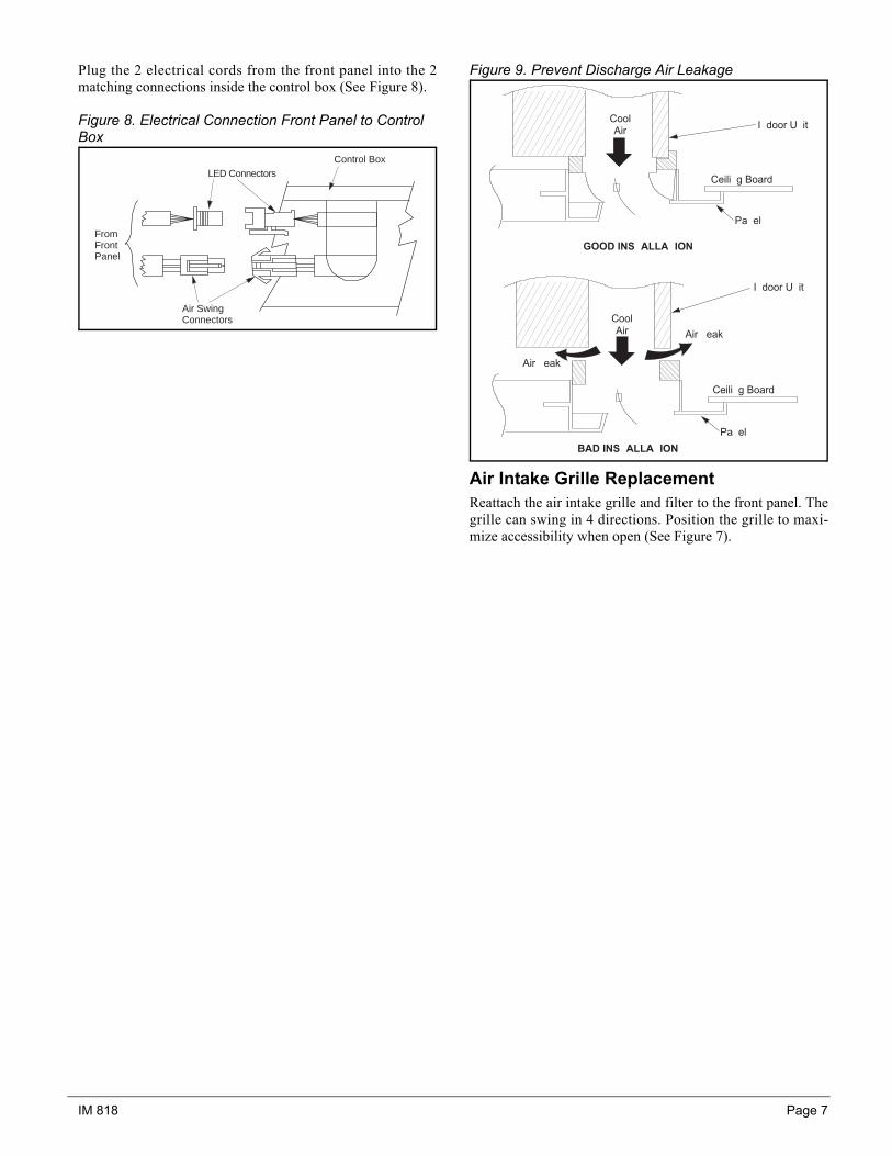
Plug the 2 electrical cords from the front panel into the 2matching connections inside the control box (See Figure 8).
Figure 8. Electrical Connection Front Panel to Control Box
Figure 9. Prevent Discharge Air Leakage
Air Intake Grille ReplacementReattach the air intake grille and filter to the front panel. Thegrille can swing in 4 directions. Position the grille to maxi-mize accessibility when open (See Figure 7).
From Front Panel
LED Connectors Control Box
Air Swing Connectors
� � � �� � �
� � � �� � �
� � � � �
� � � � �
� � � � � � � � �
� � � � � � � � �
� �
� �
� � � � � � � � �
� � � � � � � � � � �
� � � � � � � � � �
� � � � � � � � �
Page 8 IM 818
Refrigerant TubingTubing Length & ElevationCopper tubing to connect the indoor and outdoor units is sup-plied by others or it can be ordered from the factory. SeeTable 1 for requirements.
Table 1: Refrigeration Tubing Requirements
Note: The refrigerant pre-charged in the outdoor unit is for tubing length "L" upto 25 ft. See "Installation Diagram" page 5. See Table 6 on page 17 for addi-tional R-22 refrigerant required on longer runs.
Tubing Preparation• Do not use contaminated or damaged copper tubing. Do
not remove plastic, rubber plugs or brass nuts from thevalves, fittings, tubings and coils until you are ready toconnect suction or liquid line into valves or fittings.
• If any brazing work is required, ensure that the nitrogengas is passed through coil and joints while the brazingwork is done. This will eliminate soot formation on theinside wall of the copper tubing.
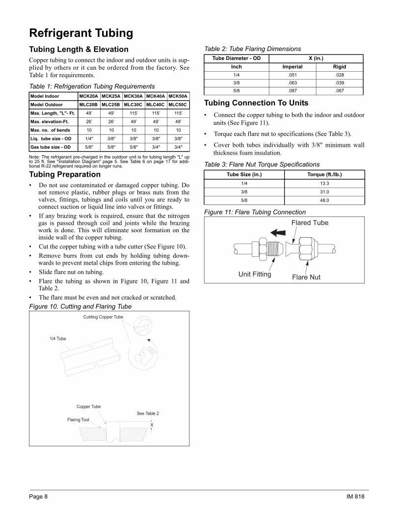
• Cut the copper tubing with a tube cutter (See Figure 10).• Remove burrs from cut ends by holding tubing down-
wards to prevent metal chips from entering the tubing.• Slide flare nut on tubing.• Flare the tubing as shown in Figure 10, Figure 11 and
Table 2.• The flare must be even and not cracked or scratched.Figure 10. Cutting and Flaring Tube
Table 2: Tube Flaring Dimensions
Tubing Connection To Units• Connect the copper tubing to both the indoor and outdoor
units (See Figure 11).
• Torque each flare nut to specifications (See Table 3).
• Cover both tubes individually with 3/8" minimum wallthickness foam insulation.
Table 3: Flare Nut Torque Specifications
Figure 11: Flare Tubing Connection
Model Indoor MCK20A MCK25A MCK30A MCK40A MCK50A
Model Outdoor MLC20B MLC25B MLC30C MLC40C MLC50C
Max. Length, "L"- Ft. 49’ 49’ 115’ 115’ 115’
Max. elevation-Ft. 26’ 26’ 49’ 49’ 49’
Max. no. of bends 10 10 10 10 10
Liq. tube size - OD 1/4" 3/8" 3/8" 3/8" 3/8"
Gas tube size - OD 5/8" 5/8" 5/8" 3/4" 3/4"
Cutrting Copper Tube
1/4 Tube
Copper Tube
Flaring ToolSee Table 2
X
Tube Diameter - OD X (in.)Inch Imperial Rigid1/4 .051 .028
3/8 .063 .039
5/8 .087 .067
Tube Size (in.) Torque (ft./lb.)1/4 13.3
3/8 31.0
5/8 48.0
Flared Tube
Flare NutUnit Fitting
IM 818 Page 9
Electrical Connections
• Wiring must be in accordance with all applicable electri-cal codes.
• Wires must not touch the refrigerant piping, compressoror any moving part.
• All electrical field wiring must be clamped at both theindoor unit and the outdoor unit.
Note: Field install 10A fuse in blue wire of outdoor unit asshown in wire diagrams for unit sizes 30, 40, and 50.
• See Table 4 and 5 for the number of wires, wire gage andfuse/circuit breaker size required.
• NEC requires an approved electrical disconnect withinsight of the unit so that anyone working on the unit canturn off the power and see that its not accidently turnedback on. This will require two disconnects, one by theoutdoor unit and one by the indoor unit.
Table 4: Wire, Fuse/Breaker Requirements - Cooling Only
Table 5: Wire, Fuse/Breaker Requirements - Heat Pump Only
* Not including the low voltage OD coil sensor cable.
WARNING
Improper installation can cause severe personal injuryor death . Wiring must be done by a qual if iedtechnician in compliance with local codes.
Unit Size 20 25 30 40 50Voltage - 60Hz. 1 Ph. 208/230
Power supply wire size 12 ga. 10 ga. 8 ga. 8 ga. 6 ga.
No. of 12 ga. wires between units 2 + gnd. 2 + gnd 3 + gnd 3 + gnd 3 + gnd
Fuse/Breaker size 20 amp. 25 amp. 35 amp. 40 amp. 55 amp.
Unit Size 20 25 30 40 50Voltage - 60Hz. 1 Ph. 208/230
Power supply wire size 12 ga. 10 ga. 8 ga. 8 ga. 6 ga.
No. of 12 ga. wires between units* 5 + gnd. 5 + gnd 6 + gnd 6 + gnd 6 + gnd
Fuse/Breaker size 20 amp. 25 amp. 35 amp. 40 amp. 55 amp.

Page 10 IM 818
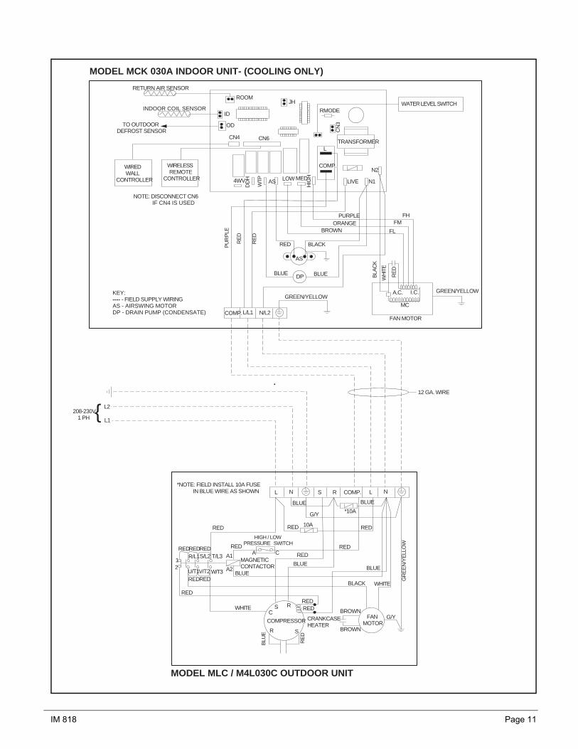
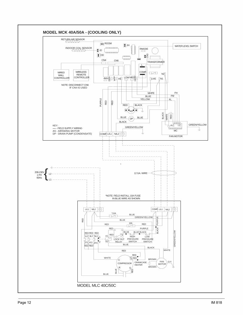
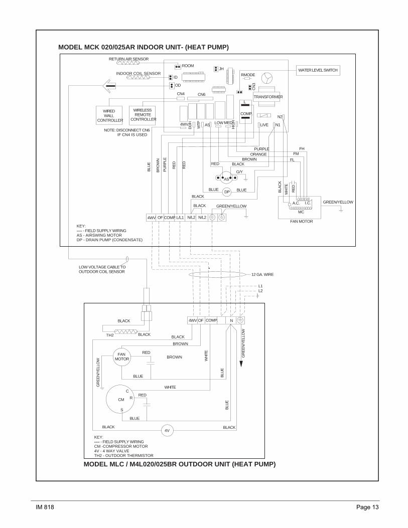
Wiring Diagrams
RETURN AIR SENSOR
INDOOR COIL SENSOR
ROOM
ID
OD
WIREDREMOTE
CONTROLLER
WIRELESSREMOTE
CONTROLLER
CN4 CN6
JH
RMODE
CN
3
TRANSFORMER
WATER LEVEL SWITCH
L
COMP.
N1
N2
LIVE4WV
DD
H
WTP AS LOW MED
HIG
H
RE
D RED BLACK
AS
BLUE BLUE BLA
CK
PURPLEORANGE
BROWN
FHFM
FL
WH
ITE
RE
D
A.C. I.C.
MC
FAN MOTOR
GREEN/YELLOWGREEN/YELLOW
COMP. N/L2
NOTE: DISCONNECT CN6 IF CN4 IS USED
KEY:---- - FIELD SUPPLY WIRINGAS - AIRSWING MOTORDP - DRAIN PUMP (CONDENSATE)
COMP.
WHITE
FANMOTOR BROWN
C
CMBLUE
DP
MODEL MCK 020/025A INDOOR UNIT- (COOLING ONLY)
MODEL MLC / M4L020/025B OUTDOOR UNIT
N
S
R
RED
TO OUTDOORDEFROST SENSOR
L/L1 N/L2
PU
RP
LE
BLACK
BLACK
RE
D
G/Y
L1L2}208/230V
60Hz
RED
BLUE BLUE
BLUE
GREEN/YELLOW
CAPACITOR
KEY:---- - FIELD SUPPLY WIRINGCM - COMPRESSOR MOTOR WITH INTERNAL OVERLOAD PROTECTOR
12 GA. WIRE
IM 818 Page 11
RETURN AIR SENSOR
INDOOR COIL SENSOR
ROOM
ID
OD
WIREDWALL
CONTROLLER
WIRELESSREMOTE
CONTROLLER
CN4 CN6
JH
RMODE
CN
3
TRANSFORMERL
COMP.
N1
N2
LIVE4WV
DD
H
WTP AS LOW MED
HIG
H
PU
RP
LE
RE
D
RE
DRED BLACK
AS
BLUE BLUE BLA
CK
PURPLEORANGE
BROWN
FHFM
FL
WH
ITE
RE
D
A.C. I.C.
MC
FAN MOTOR
GREEN/YELLOWGREEN/YELLOW
COMP.L/L1 N/L2
NOTE: DISCONNECT CN6 IF CN4 IS USED
KEY:---- - FIELD SUPPLY WIRINGAS - AIRSWING MOTORDP - DRAIN PUMP (CONDENSATE)
208-230V1 PH
L2
L1
10A
REDRED
BLUEREDRED
RED
R/L1S/L2 T/L3
U/T1V/T2 W/T3 A2
A1
BLACK
RED
BLUE
WHITE
COMP. L N
GR
EE
N/Y
ELL
OW
RE
D
BLU
E
WHITE RED
G/YFANMOTOR
BROWN
BROWN
C
R S
COMPRESSOR CRANKCASEHEATER
{
*NOTE: FIELD INSTALL 10A FUSE IN BLUE WIRE AS SHOWN
DP
MODEL MCK 030A INDOOR UNIT- (COOLING ONLY)
MODEL MLC / M4L030C OUTDOOR UNIT
S RL N
BLUE
*10A
RED
G/Y
HIGH / LOW PRESSURE SWITCH
RED REDRED
BLUEBLUE
MAGNETICCONTACTOR
S R
RED
RED
RED
12
A C
TO OUTDOORDEFROST SENSOR
WATER LEVEL SWITCH
12 GA. WIRE
Page 12 IM 818
RETURN AIR SENSOR
INDOOR COIL SENSOR
ROOM
ID
OD
WIREDWALL
CONTROLLER
WIRELESSREMOTE
CONTROLLER
CN4 CN6
JH
RMODE
CN
3
TRANSFORMERL
COMP.
N1
N2
LIVE4WV
DD
H
WTP AS LOW MED
HIG
H
PU
RP
LE
RE
D
RE
DRED BLACK
AS
BLUE BLUE BLA
CK
WHITEBLUE
YELLOW
FHFM
FL
WH
ITE
RE
D
A.C. I.C.
MC
FAN MOTOR
GREEN/YELLOWGREEN/YELLOW
COMP.L/L1 N/L2
NOTE: DISCONNECT CN6 IF CN4 IS USED
KEY:---- - FIELD SUPPLY WIRINGAS - AIRSWING MOTORDP - DRAIN PUMP (CONDENSATE)
208-230V1 PH60Hz
L2
L1
10A
RE
D
RED
RED RED RED
RED
RED
RED
RED RED
RED
1L1 3L2 5L3
2T1 4T2 6T3
1
2 A2
A1
BLUE
BLACK
BLUE BLUE
RED
BLACK BLA
CK
BLUE
BLUEGREEN/YELLOW
PURPLE
PU
RP
LE
WHITE
COMP. L/L1 N/L2
GR
EE
N/Y
ELL
OW
RE
D
BLU
E
WHITE RED
G/YFANMOTOR
BROWN
BROWN
C
R S
COMPRESSOR
BLUE
CRANKCASEHEATER
LOWPRESSURE
SWITCH
HIGHPRESSURE
SWITCHLOCK OUT
RELAY
{
2
*10A
*NOTE: FIELD INSTALL 10A FUSE IN BLUE WIRE AS SHOWN
DP
MODEL MCK 40A/50A - (COOLING ONLY)
MODEL MLC 40C/50C
L/L1 N/L2
WATER LEVEL SWITCH
12 GA. WIRE
BLACK
IM 818 Page 13
RETURN AIR SENSOR
INDOOR COIL SENSOR
ROOM
ID
OD
WIREDWALL
CONTROLLER
WIRELESSREMOTE
CONTROLLER
CN4 CN6
JH
RMODE
CN
3
TRANSFORMERL
COMP.
N1
N2
LIVE4WV
DD
H
WTP AS LOW MED
HIG
H
RE
D RED BLACK
AS
BLUE BLUE BLA
CK
PURPLEORANGE
BROWN
FHFM
FL
WH
ITE
RE
D
A.C. I.C.
MC
FAN MOTOR
GREEN/YELLOWGREEN/YELLOW
COMP. N/L2
NOTE: DISCONNECT CN6 IF CN4 IS USED
KEY:---- - FIELD SUPPLY WIRINGAS - AIRSWING MOTORDP - DRAIN PUMP (CONDENSATE)
WH
ITE
FANMOTOR
CM
DP
MODEL MCK 020/025AR INDOOR UNIT- (HEAT PUMP)
MODEL MLC / M4L020/025BR OUTDOOR UNIT (HEAT PUMP)
L/L1 N/L2
PU
RP
LE
BLACK
BLACK
RE
DG/Y
GR
EE
N/Y
ELL
OW
KEY:---- - FIELD SUPPLY WIRINGCM -COMPRESSOR MOTOR4V - 4 WAY VALVETH2 - OUTDOOR THERMISTOR
OF4WV
BLU
E
BR
OW
N
COMP. NOF4WV
BLU
EB
LUE
BLACK
GR
EE
N/Y
ELL
OW
RED
RED
WHITE
BLACK4V
BLACK
BLACK
BROWN
BROWN
BLACK
BLUE
BLUE
C
R
S
TH2
LOW VOLTAGE CABLE TOOUTDOOR COIL SENSOR
L2L1
12 GA. WIRE
WATER LEVEL SWITCH
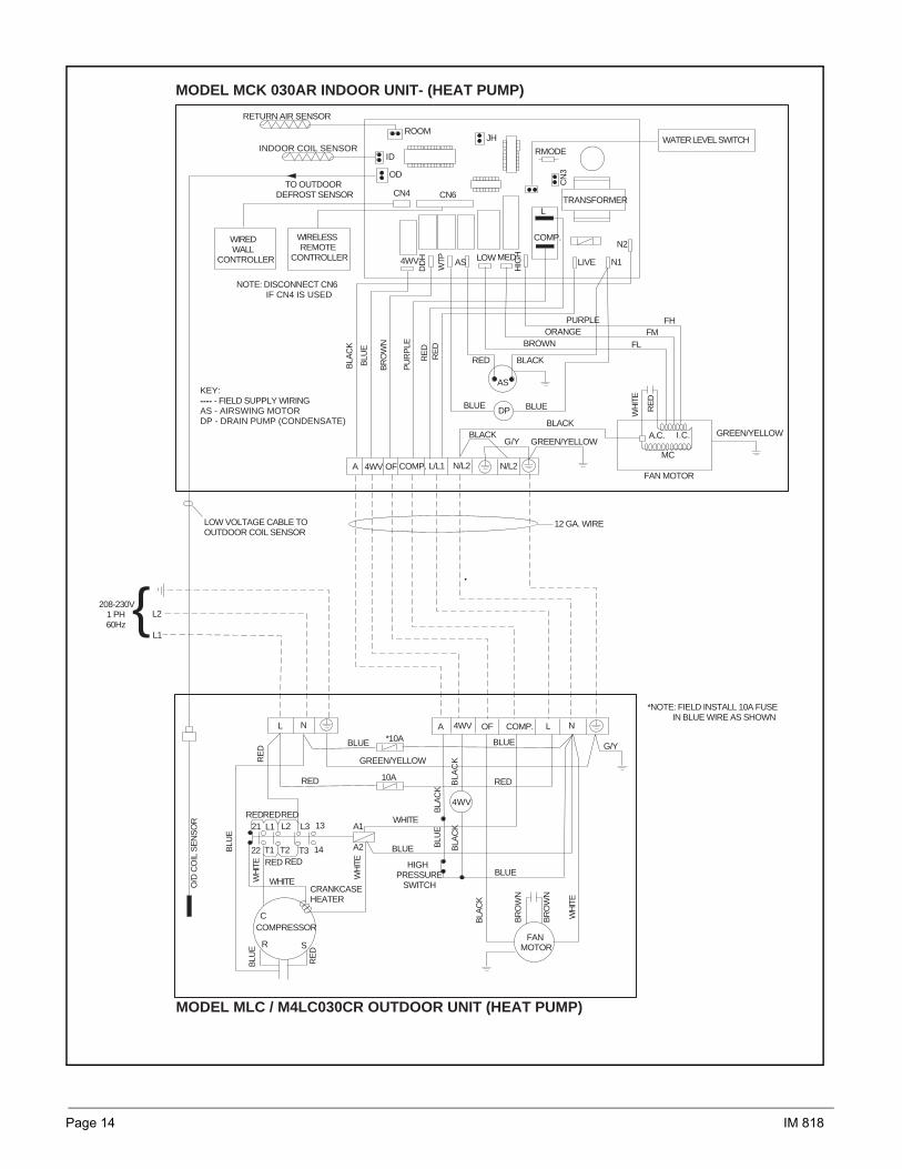
Page 14 IM 818
RETURN AIR SENSOR
INDOOR COIL SENSOR
ROOM
ID
OD
WIREDWALL
CONTROLLER
WIRELESSREMOTE
CONTROLLER
CN4 CN6
JH
RMODE
CN
3
TRANSFORMERL
COMP.
N1
N2
LIVE4WV
DD
H
WTP AS LOW MED
HIG
H
PU
RP
LE
RE
DR
ED
RED BLACK
AS
BLUE BLUE
PURPLEORANGE
BROWN
FHFM
FL
WH
ITE
RE
D
A.C. I.C.
MC
FAN MOTOR
GREEN/YELLOW
NOTE: DISCONNECT CN6 IF CN4 IS USED
KEY:---- - FIELD SUPPLY WIRINGAS - AIRSWING MOTORDP - DRAIN PUMP (CONDENSATE)
208-230V1 PH60Hz
L2
L1
10A
REDRED
RED RED
21 L2 L3
22 T2 T3 A2
A1
BLUE
WHITE
COMP. L N
RE
D
BLU
E
C
R S
COMPRESSOR
{
*NOTE: FIELD INSTALL 10A FUSE IN BLUE WIRE AS SHOWN
DP
MODEL MCK 030AR INDOOR UNIT- (HEAT PUMP)
MODEL MLC / M4LC030CR OUTDOOR UNIT (HEAT PUMP)
A 4WVL N
BLUE *10A
RED
G/Y
HIGHPRESSURE SWITCH
RED
RED
TO OUTDOORDEFROST SENSOR
OF
GREEN/YELLOW
COMP. N/L2L/L1 N/L2
BLACK
OF4WV
G/Y
A
BLU
E
BLA
CK
BR
OW
N
BLACK
L1
T1
13
14BLU
E
WH
ITE
WH
ITE
CRANKCASEHEATER
GREEN/YELLOW
WHITE
BLUE
BLUE
BR
OW
N
BR
OW
N
FANMOTOR
WH
ITE
BLA
CK
BLU
EB
LAC
K
RE
D
O/D
CO
IL S
EN
SO
R
4WV
BLA
CK
BLA
CK
LOW VOLTAGE CABLE TOOUTDOOR COIL SENSOR
WATER LEVEL SWITCH
12 GA. WIRE
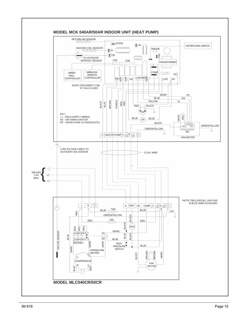
IM 818 Page 15
RETURN AIR SENSOR
INDOOR COIL SENSOR
ROOM
ID
OD
WIREDWALL
CONTROLLER
WIRELESSREMOTE
CONTROLLER
CN4 CN6
JH
RMODE
CN
3
TRANSFORMERL
COMP.
N1
N2
LIVE4WV
DD
H
WTP AS LOW MED
HIG
H
PU
RP
LE
RE
DR
ED
RED BLACK
AS
BLUE BLUE
WHITEBLUE
YELLOW
FHFM
FL
WH
ITE
RE
D
A.C. I.C.
MC
FAN MOTOR
GREEN/YELLOW
NOTE: DISCONNECT CN6 IF CN4 IS USED
KEY:---- - FIELD SUPPLY WIRINGAS - AIR SWING MOTORDP - DRAIN PUMP (CONDENSATE)
208-230V1 PH60Hz
L2
10A
RED
1L1 5L3 1
2T1 6T3 2 A2
A1
BLUE
COMP. L N
RE
D
BLU
E
C
R S
COMPRESSOR
{
*NOTE: FIELD INSTALL 10A FUSE IN BLUE WIRE AS SHOWN
DP
MODEL MCK 040AR/50AR INDOOR UNIT (HEAT PUMP)
MODEL MLC040CR/50CR
A 4WVL N
BLUE *10A
RED
G/Y
HIGHPRESSURE SWITCH
RED
RE
D
TO OUTDOORDEFROST SENSOR
OF
GREEN/YELLOW
COMP. L1 L2OF4WVA
BLU
E
BLA
CK
BR
OW
N
BLACK
3L2
4T2BLU
E
WH
ITE
WH
ITE
CRANKCASEHEATER
GREEN/YELLOW
WHITE
BLUE
BLUE
BR
OW
N
BR
OW
N
FANMOTOR
WH
ITE
BLA
CK
BLU
EB
LAC
K
RE
D
O/D
CO
IL S
EN
SO
R
4WV
BLA
CK
BLA
CK
LOW VOLTAGE CABLE TOOUTDOOR COIL SENSOR
WATER LEVEL SWITCH
12 GA. WIRE
L N
L1 L2
L1
RED
WH
ITE
RE
D
RE
D

Page 16 IM 818
CM
FM
C
S
R
CAPACITOR
CAPACITOR
WHITE
RED
BLUE
BLUE BLUE
COMP N
GREEN/YELLOW
KEY CM - COMPRESSOR MOTOR FM - OUTDOOR FAN MOTOR FSCM - FAN SPEED CONTROL MODULE
12 GA. WIRE BY OTHERS
YELLOW
ORANGE
1 2 3 4 5
FSCM
OUTDOOR COIL SENSOR
(TO INDOOR UNIT)
MODEL : MLC 20B - 25B OUTDOOR UNIT - COOLING ONLY - OPTIONAL LOW AMBIENT KIT
OL
MODEL : MLC20BR - 25BR OUTDOOR UNIT - HEAT PUMP - OPTIONAL LOW AMBIENT KIT
FM CM
4 3 2 1
FSCM
COMP. N OF 4V
(TO INDOOR UNIT)
RED
BLACK TH2
BLACK
4V BLACK BLACK
OR
AN
GE
BLA
CK
YE
LLO
W
BR
OW
N
BROWN BR
OW
N
BLUE BLA
CK
WH
ITE
BLUE
BLUE
WH
ITE
BLA
CK
GR
EE
N/Y
EL
RED
BLU
E
C
S R
KEY FM - FAN MOTOR CM - COMPRESSOR MOTOR 4V - 4 WAY VALVE TH2 - OUTDOOR THERMISTOR FSCM - FAN SPEED CONTROL MODULE
E
E
WHITE
BLUE
RED
BROWN
BLU
E
BLU
E
12 GA. WIRE BY OTHERS
BLUE
IM 818 Page 17
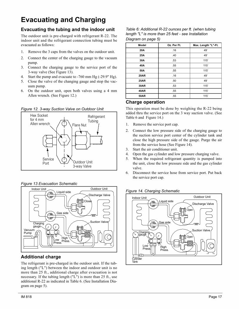
Evacuating and ChargingEvacuating the tubing and the indoor unitThe outdoor unit is pre-charged with refrigerant R-22. Theindoor unit and the refrigerant connection tubing must beevacuated as follows:
1. Remove the 3 caps from the valves on the outdoor unit.2. Connect the center of the charging gauge to the vacuum
pump.3. Connect the charging gauge to the service port of the
3-way valve (See Figure 13).4. Start the pump and evacuate to -760 mm Hg (-29.9" Hg).5. Close the valve of the changing gauge and stop the vac-
uum pump.6. On the outdoor unit, open both valves using a 4 mm
Allen wrench. (See Figure 12.)
Figure 12. 3-way Suction Valve on Outdoor Unit
Figure 13 Evacuation Schematic
Additional chargeThe refrigerant is pre-charged in the outdoor unit. If the tub-ing length ("L") between the indoor and outdoor unit is nomore than 25 ft., additional charge after evacuation is notnecessary. If the tubing length ("L") is more than 25 ft., useadditional R-22 as indicated in Table 6. (See Installation Dia-gram on page 5).
Table 6: Additional R-22 ounces per ft. (when tubing length "L" is more than 25 feet - see Installation Diagram on page 5)
Charge operationThis operation must be done by weighing the R-22 beingadded thru the service port on the 3 way suction valve. (SeeTable 6 and Figure 14.)
1. Remove the service port cap.2. Connect the low pressure side of the charging gauge to
the suction service port center of the cylinder tank andclose the high pressure side of the gauge. Purge the airfrom the service hose (See Figure 14).
3. Start the air conditioner unit.4. Open the gas cylinder and low pressure charging valve.5. When the required refrigerant quantity is pumped into
the unit, close the low pressure side and the gas cylindervalve.
6. Disconnect the service hose from service port. Put backthe service port cap.
Figure 14. Charging Schematic
Hex Socketfor 4 mmAllen wrench Flare Nut
RefrigerantTubing
ServicePort Outdoor Unit
3-way Valve
Indoor UnitLiquid side
Outdoor Unit
Close
Discharge Valve
Suction Valve
Close
Gas side
Vacuum Pump
HighPress.Low
Press.
Model Oz. Per Ft. Max. Length "L"-Ft.
20A .16 49’
25A .40 49’
30A .53 115’
40A .55 115’
50A .55 115’
20AR .16 49’
25AR .50 49’
30AR .53 115’
40AR .55 115’
50AR .55 115’
Indoor Unit Outdoor UnitLiquid side
Gas side
HighPress.
LowPress.
Discharge Valve
Suction Valve

Page 18 IM 818
Remote Controller Operation GuideTransmission source• The source where the signal is
transmitted.
ON Timer Setting• Press the SET button will activate
the on timer function.
• Set the desired on time by pressingthe SET button continuously. If thetimer is set to 7.30am, the air con-ditioner will turn on at 7.30 sharp.
• Press the CLR button to cancel theon timer setting.
Fan Speed Selection• Press the button until the desired
fan option displays (auto, low,med. or high). "Auto" automaticallyselects high fan until room temper-ature is within 2oF of setting, thenswitches to low speed. Fan runscontinuous in Cool and cycles inHeat.
Signal Transmission Indication• Blinks to confirm the last setting
was sent to the unit.
On/Off Button• Press once to start the air
conditioner.
• Press again to stop the airconditioner.
Operation mode• Press the MODE button to select
the type of operating mode.
• For cooling only unit, the availablemodes are : COOL, DRY & FAN.
• For heat pump unit, the availablemodes are: AUTO, COOL, DRY,FAN & HEAT.
Temperature Setting• Set the desired room temperature
by pressing the buttons to increaseor decrease the set temperature.
• The temperature setting range isfrom 60°F to 86°F.
• Press both buttons simultaneouslyto toggle the temperature settingbetween °C and °F.
Automatic Air Swing• Press the SWING button to
activate the automatic air swingfunction.
• To distribute the air to a specific direction, press the SWINGbutton and wait until the airconditioner baffle swings to thedesired direction. Press thebutton again to hold it.
Sleep mode setting• Press the button to activate sleep
mode. This function is availableunder COOL, HEAT & AUTO mode.
• In COOL mode, the set temperature will increase 1.0°F after 30 minutes,2°F after 1 hour and a total of 4°Fafter 2 hours.
• In HEAT mode, the set temperaturewill decrease 2°F after 30 minutes,4°F after 1 hour and a total of 5°Fafter 2 hours.
OFF Timer Setting• Press the SET button will activate
the off timer function.
• Set the desired off time by pressingthe SET button continuously.
• Press the CLR button to cancel theoff timer setting.
Clock Time Setting• Press button + or - to
increase or decrease the clock time.
Symbol Identification
Cool Dry Fan Heat Sleep Power Timer Auto Fan Speed
low med high
Auto

IM 818 Page 19
Netware 2 - Wired Wall Control (Optional)Features:1. Modes - Cool, Heat, Auto, Dry, Fan and Off.2. Temperature Range: 60° F to 86° F. (Press both arrows
simultaneously to convert from °C to °F or °F to °C).3. Timer - Seven day clock capable of a different On/Off
time for each day of the week. Note: Hold button is usedto temporarily override timer.
4. Shows time of day.5. Electronic lockout to prevent tampering.6. Fan Speeds - Low, medium, high and auto.7. Sleep - Sets temperature back for sleeping.8. Swing - Swings or positions air baffle for better air dis-
tribution.9. Display normally shows room temperature. (Momen-
tarily shows set point when a change is made.)10. Heat symbol ( ) blinks while outdoor coil defrosts
(heat pump only).11. Error codes blink on display:
E1 - Room sensor loose or defective.E2 - Indoor coil sensor loose or defective.E3 - Outdoor coil sensor loose or defective.E4 - Compressor cycling on overload.E5 - Low refrigerant charge.
For more detail, see manual that ships with the Wall Control.
SLEEP FAN MODESET TEMP
SWING ON TIMER OFF TIMER
HOLD DAY HOUR MINUTECLOCK
ON/OFF
°F°C
COOLTEMP.HEATTEMP.ROOMTEMP.
MON TUE WED THU FRI SAT SUN
ON
OFFAMPM
TIME ACTIVATE SET TIMER SET CLOCK
SET CLOCK DRY AUTO COOL HEAT FAN
AUTO SLEEP
SWING
Page 20 IM 818
Special FeaturesDry mode• Select this mode when the standard Cool mode does not
provide sufficient dehumidification. The compressor andindoor low fan will cycle together and will operate forlonger periods of timeto provide the increased rate ofdehumidification. As a result, the room temperature dif-ferential may increase slightly.
Heat mode (heat pump only)• When the unit is switched on from cold start or defrosting
cycle, the indoor fan will start to operate only after thecoil warms up.
• When the set temperature is achieved, the indoor fan willoperate until the coil cools down.
Overheating protection (heat pump only)• In case the coil overheats (145°F), the compressor will
cut out.Frost prevention• If the indoor coil starts to frost, an LED light will blink to
indicate that the unit is in defrost.Fan speed and rated cooling capacity• The rated cooling capacity is provided at high indoor fan
speed.
• The cooling capacity is slightly lower when the unit isoperating at MEDIUM and LOW fan speed.
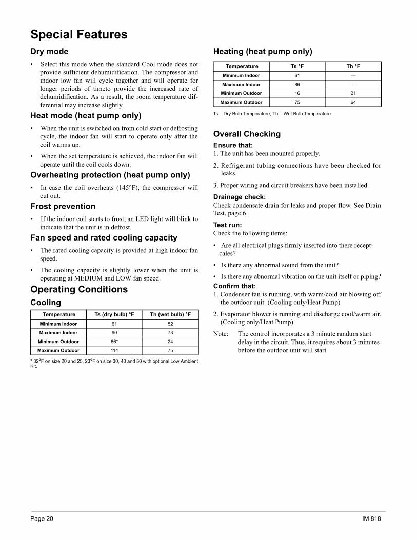
Operating ConditionsCooling
* 32°F on size 20 and 25, 23°F on size 30, 40 and 50 with optional Low AmbientKit.
Heating (heat pump only)
Ts = Dry Bulb Temperature, Th = Wet Bulb Temperature
Overall CheckingEnsure that:1. The unit has been mounted properly.
2. Refrigerant tubing connections have been checked forleaks.
3. Proper wiring and circuit breakers have been installed.
Drainage check:Check condensate drain for leaks and proper flow. See DrainTest, page 6.
Test run:Check the following items:
• Are all electrical plugs firmly inserted into there recept-cales?
• Is there any abnormal sound from the unit?
• Is there any abnormal vibration on the unit itself or piping?Confirm that:1. Condenser fan is running, with warm/cold air blowing off
the outdoor unit. (Cooling only/Heat Pump)
2. Evaporator blower is running and discharge cool/warm air.(Cooling only/Heat Pump)
Note: The control incorporates a 3 minute randum start delay in the circuit. Thus, it requires about 3 minutes before the outdoor unit will start.
Temperature Ts (dry bulb) °F Th (wet bulb) °F Minimum Indoor 61 52
Maximum Indoor 90 73
Minimum Outdoor 66* 24
Maximum Outdoor 114 75
Temperature Ts °F Th °F Minimum Indoor 61 —
Maximum Indoor 86 —
Minimum Outdoor 16 21
Maximum Outdoor 75 64
IM 818 Page 21
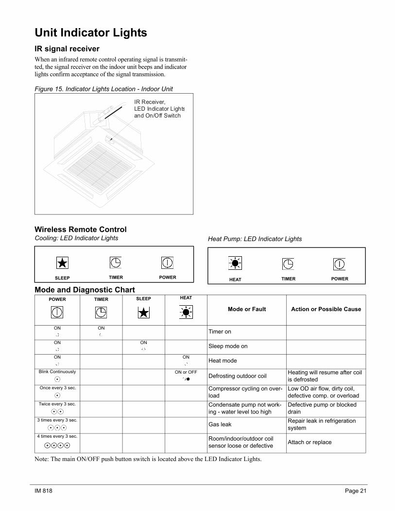
Unit Indicator LightsIR signal receiverWhen an infrared remote control operating signal is transmit-ted, the signal receiver on the indoor unit beeps and indicator lights confirm acceptance of the signal transmission.
Figure 15. Indicator Lights Location - Indoor Unit
Wireless Remote ControlCooling: LED Indicator Lights
Mode and Diagnostic Chart
Heat Pump: LED Indicator Lights
Note: The main ON/OFF push button switch is located above the LED Indicator Lights.
IR Receiver,LED Indicator Lightsand On/Off Switch
SLEEP TIMER POWER HEAT TIMER POWER
POWER TIMER SLEEP HEAT
Mode or Fault Action or Possible Cause
ON ONTimer on
ON ONSleep mode on
ON ONHeat mode
Blink Continuously ON or OFFDefrosting outdoor coil Heating will resume after coil
is defrosted Once every 3 sec. Compressor cycling on over-
loadLow OD air flow, dirty coil, defective comp. or overload
Twice every 3 sec. Condensate pump not work-ing - water level too high
Defective pump or blocked drain
3 times every 3 sec.Gas leak Repair leak in refrigeration
system4 times every 3 sec. Room/indoor/outdoor coil
sensor loose or defective Attach or replace
Page 22 IM 818
Startup After Extended Shutdown• Inspect thoroughly and clean indoor and outdoor units.
• Clean or replace air filter.
• Clean condensate drain line.
• Clean clogged indoor and outdoor coils.
• Check fan imbalance before operation.
• Tighten all wire connections.
• Check for refrigerant leakage.
Note: The crankcase heater should be energized for at least6 hours before starting the unit.
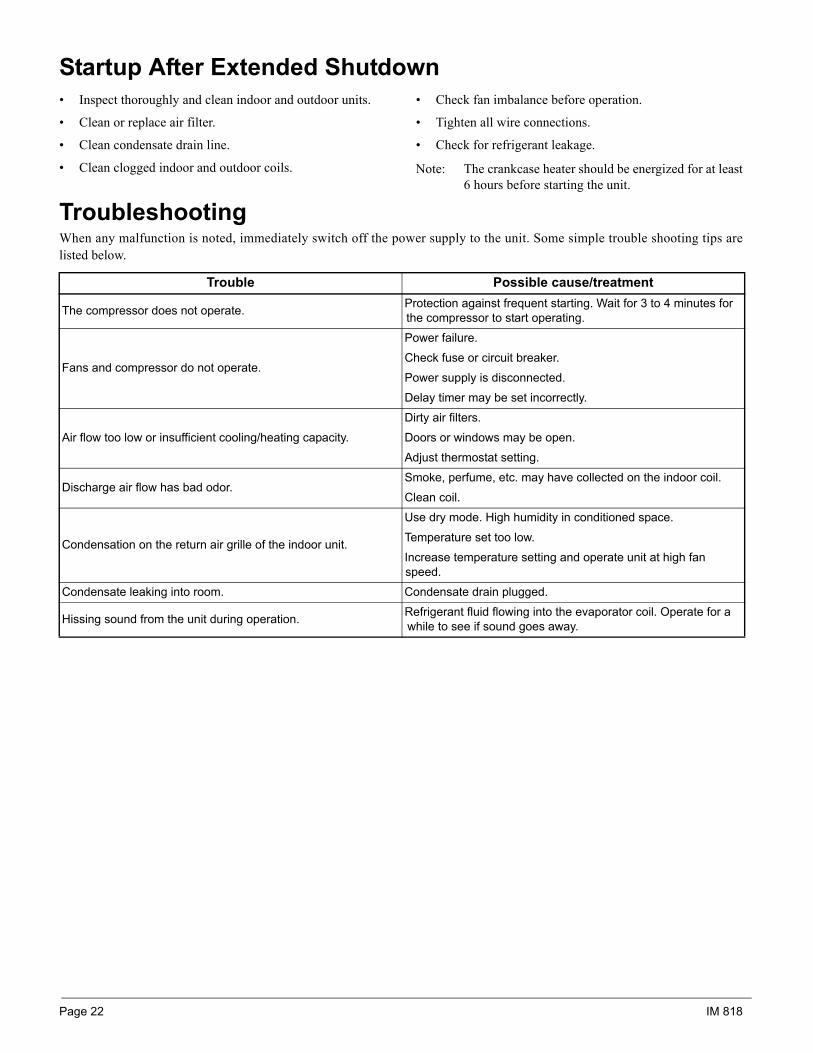
TroubleshootingWhen any malfunction is noted, immediately switch off the power supply to the unit. Some simple trouble shooting tips arelisted below.
Trouble Possible cause/treatment
The compressor does not operate. Protection against frequent starting. Wait for 3 to 4 minutes for the compressor to start operating.
Fans and compressor do not operate.
Power failure.
Check fuse or circuit breaker.
Power supply is disconnected.
Delay timer may be set incorrectly.
Air flow too low or insufficient cooling/heating capacity.
Dirty air filters.
Doors or windows may be open.
Adjust thermostat setting.
Discharge air flow has bad odor.Smoke, perfume, etc. may have collected on the indoor coil.
Clean coil.
Condensation on the return air grille of the indoor unit.
Use dry mode. High humidity in conditioned space.
Temperature set too low.
Increase temperature setting and operate unit at high fan speed.
Condensate leaking into room. Condensate drain plugged.
Hissing sound from the unit during operation. Refrigerant fluid flowing into the evaporator coil. Operate for a while to see if sound goes away.
IM 818 Page 23
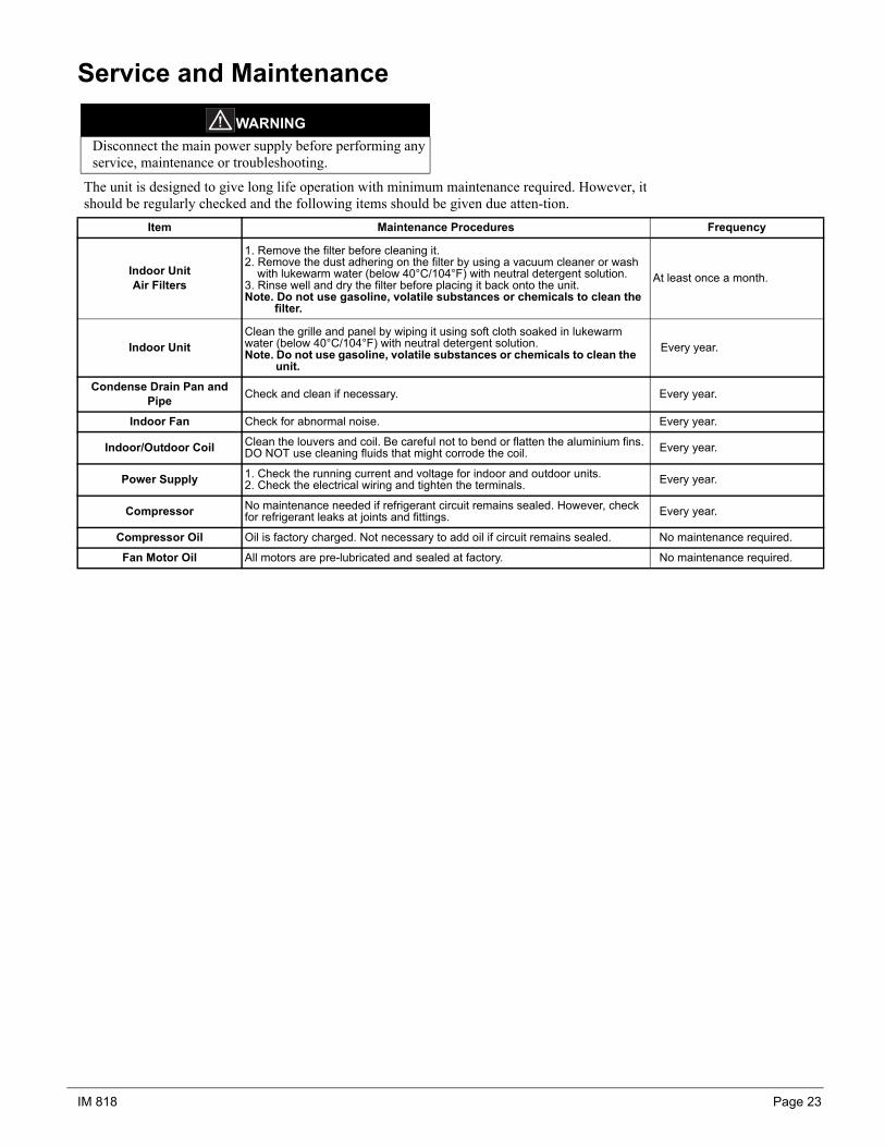
Service and Maintenance
The unit is designed to give long life operation with minimum maintenance required. However, it should be regularly checked and the following items should be given due atten-tion.
WARNINGDisconnect the main power supply before performing any service, maintenance or troubleshooting.
Item Maintenance Procedures Frequency
Indoor Unit Air Filters
1. Remove the filter before cleaning it.2. Remove the dust adhering on the filter by using a vacuum cleaner or wash
with lukewarm water (below 40°C/104°F) with neutral detergent solution.3. Rinse well and dry the filter before placing it back onto the unit.Note. Do not use gasoline, volatile substances or chemicals to clean the
filter.
At least once a month.
Indoor UnitClean the grille and panel by wiping it using soft cloth soaked in lukewarm water (below 40°C/104°F) with neutral detergent solution.Note. Do not use gasoline, volatile substances or chemicals to clean the
unit.Every year.
Condense Drain Pan and Pipe Check and clean if necessary. Every year.
Indoor Fan Check for abnormal noise. Every year.
Indoor/Outdoor Coil Clean the louvers and coil. Be careful not to bend or flatten the aluminium fins. DO NOT use cleaning fluids that might corrode the coil. Every year.
Power Supply 1. Check the running current and voltage for indoor and outdoor units.2. Check the electrical wiring and tighten the terminals. Every year.
Compressor No maintenance needed if refrigerant circuit remains sealed. However, check for refrigerant leaks at joints and fittings. Every year.
Compressor Oil Oil is factory charged. Not necessary to add oil if circuit remains sealed. No maintenance required.
Fan Motor Oil All motors are pre-lubricated and sealed at factory. No maintenance required.
Page 24 IM 818
© 2004 Daikin
This document contains the most current product information as of this printing. For the most up-to-date product information, please go to www.DaikinApplied.com.
Daikin Applied800.432.1342www.DaikinApplied.com