installation and instruction manual/media/resources/phase dynamics/t... · familiarization with...
TRANSCRIPT

INSTALLATIONAND
INSTRUCTIONMANUAL
PHASE DYNAMICS, INC.Water in Hydrocarbon Analyzer
December 10, 2002Document Number 0040-00000-000
Revision I
IMPORTANT NOTE
Your Phase Dynamics analyzer is a MATCHED SET of a measurement section and acomputer. For proper operation, the following ID numbers of measurement section andcomputer MUST BE used together. The serial number is typically located on the end ofthe measurement section opposite the explosion-proof housing. The computer ID islocated on the EPROM chip located on the processor board of the computer chassis.
The MATCHED SET of your analyzer is:
Measurement Section S/N: _________________________
EPROM ID: _________________________

PHASE DYNAMICS, INC.
ii
WARRANTY
This Phase Dynamics product is warranted against defects in material and workmanshipfor a period of one year from date of shipment. During the warranty period, PhaseDynamics will, at it's option, either repair or replace products which are defective.
For warranty service or repair, this product must be returned to Phase Dynamics. Buyershall prepay shipping charges to Phase Dynamics and Phase Dynamics shall payshipping charges to return the product to the Buyer. However, Buyer shall pay ALLshipping charges, duties, and taxes for products returned to (or from) Phase Dynamicsfrom (or to) a country other than the United States of America.
Phase Dynamics warrants that its software and firmware designated by Phase Dynamicsfor use with an instrument will execute its programming instructions when properlyinstalled on that instrument. Phase Dynamics does not warrant that the operation of theinstrument, or software, or firmware will be uninterrupted or error free.
LIMITATION OF WARRANTY
The foregoing warranty shall not apply to defects resulting from improper or inadequatemaintenance by Buyer, Buyer-supplied software or interfacing, unauthorized modificationor misuse, operation outside of the environmental specifications for the product, orimproper site preparation or maintenance.
EXCLUSIVE REMEDIES
The remedies provided herein are Buyer's sole and exclusive remedies. PhaseDynamics shall not be liable for any direct, indirect, special, incidental, or consequentialdamages, whether based on contract, tort, or any other legal theory.
This document is Revision I per Phase Dynamics Engineering Change Order Number163.

Water in Hydrocarbon Analyzer
iii
PREFACE
SAFETY INFORMATION
THIS PRODUCT AND RELATED DOCUMENTATION MUST BE REVIEWED FORFAMILIARIZATION WITH SAFETY MARKINGS AND INSTRUCTIONS BEFOREOPERATION.
SAFETY LABELS
This product is provided with a protective earth terminal, located on the power inputboard which is located under the front panel on the left side of the chassis.
BEFORE APPLYING POWER
Verify that the line voltage is appropriate for the analyzer and the correct fuse is installed.Refer to Installation section.
ELECTROSTATIC DISCHARGE
All of the printed circuit board assemblies of this system are susceptible to damage orfailure from electrostatic discharge (ESD).
WARNINGDenotes a hazard. It calls attention to a procedure, practice, or the like,which, if not correctly performed or adhered to, could result in personalinjury. Do not proceed beyond a WARNING sign until the indicatedconditions are fully understood and met.
CAUTIONDenotes a hazard. It calls attention to an operating procedure, practice, orthe like, which, if not correctly performed or adhered to, could result indamage to or destruction of part or all of the product. Do not proceedbeyond a CAUTION sign until the indicated conditions are fully understoodand met.

PHASE DYNAMICS, INC.
iv
SAFETY EARTH GROUND
Any interruption of the protective grounding conductor (inside or outside the instrument)or disconnecting the protective earth terminal will cause a potential shock hazard thatcould result in personal injury.
Whenever it is likely that the protection has been impaired, the instrument must be madeinoperative and be secured against any unintended operation.
If this instrument is to be energized via an autotransformer (for voltage reduction), makesure the common terminal is connected to the earth pole terminal (neutral) of the powersource.
Instructions for adjustments while covers are removed and for servicing are for use byservice-trained personnel only. To avoid dangerous electrical shock, do not performsuch adjustments or servicing unless qualified to do so.
For continued protection against fire, replace the line fuse only with a fuse of the samecurrent rating and type (for example, normal blow or time delay). Do not use repairedfuses or short-circuited fuse holder.
CAUTIONProtect circuit boards from ESD at all times.
WARNINGAn uninterruptible safety earth ground must be provided from the main
power source to the product input wiring terminals. Using Neutral as EarthGround may cause a potential shock hazard that could result in personal
injury.

Water in Hydrocarbon Analyzer
v
CONTENTS
1. SPECIFICATIONS .................................................................................................2
2. SYSTEM OVERVIEW ............................................................................................42.1 DESCRIPTION..................................................................................................42.2 TYPICAL OPERATION ........................................................................................62.3 PRINCIPAL OF OPERATION (OSCILLATOR LOAD PULL)...........................................7
3. INSTALLATION...................................................................................................103.1 PRE-INSTALLATION NOTES..............................................................................103.2 MOUNTING CONSIDERATIONS .........................................................................10
3.2.1 Measurement section ......................................................................103.2.2 Electronics unit ................................................................................11
3.3 INSTALLATION DRAWINGS ...............................................................................113.4 BASIC ELECTRICAL HOOK-UP ..........................................................................113.5 CONNECTION OF FEATURES AND OPTIONS .......................................................17
3.5.1 Analog output (4-20 mA or 0-20 mA)...............................................183.5.2 Alarm relay output ...........................................................................183.5.3 Error relay output.............................................................................193.5.4 RS-422 interface .............................................................................193.5.5 Current input ...................................................................................193.5.6 Pulse input ......................................................................................20
4. GENERAL OPERATION AND INITIAL START-UP ............................................214.1 USER INTERFACE SWITCHES AND FUNCTIONS...................................................224.2 INITIAL START-UP...........................................................................................234.3 LCD ADJUSTMENTS.......................................................................................24
5. MODES OF OPERATION....................................................................................265.1 NORMAL MODE .............................................................................................26
5.1.1 Accessing the Normal Mode ...........................................................265.1.2 MENU items for the Normal Mode...................................................27
5.2 SUPERVISOR MODE.......................................................................................305.2.1 Accessing the Supervisor Mode......................................................305.2.2 Supervisor Mode display .................................................................315.2.3 Defining the MENU items for the User-defined Mode......................31
5.3 USER-DEFINED MODE....................................................................................325.3.1 Accessing the User-defined Mode...................................................32
5.4 TECHNICIAN MODE ........................................................................................335.4.1 Accessing the Technician Mode......................................................335.4.2 Technician Mode display.................................................................335.4.3 MENU items for the Technician Mode.............................................345.4.4 Reference current............................................................................365.4.5 Resetting factory coefficients ..........................................................37

PHASE DYNAMICS, INC.
vi
6. CALIBRATION PROCEDURE.............................................................................386.1 FACTORY CALIBRATION ..................................................................................386.2 FIELD CALIBRATION .......................................................................................38
7. COMPREHENSIVE LIST OF ERROR MESSAGES............................................41
8. THEORY OF OPERATION..................................................................................448.1 DETAILED DESCRIPTION OF FREQUENCY RESPONSE .........................................448.2 TEMPERATURE COMPENSATION ......................................................................48
9. DETAILED FUNCTIONAL DESCRIPTIONS .......................................................509.1 AUTOMATIC SYSTEMS TEST ............................................................................509.2 POWER-UP SELF TEST ...................................................................................509.3 BUILT-IN TEST ...............................................................................................509.4 NORMAL OPERATION......................................................................................519.5 AC INPUT BOARD ..........................................................................................519.6 DC INPUT BOARD ..........................................................................................529.7 MOTHERBOARD.............................................................................................529.8 AC POWER SUPPLY BOARD ............................................................................529.9 DC POWER SUPPLY BOARD ............................................................................529.10 MICROPROCESSOR BOARD.............................................................................539.11 FREQUENCY BOARD.......................................................................................539.12 ANALOG INPUT BOARD ...................................................................................539.13 ANALOG OUTPUT BOARD ................................................................................549.14 DISPLAY BOARD ............................................................................................549.15 MICROWAVE OSCILLATOR MODULE..................................................................54
10. INSTRUMENT REPAIR AND SERVICE..............................................................5510.1 ASSISTANCE AND FACTORY ADDRESS..............................................................5510.2 ELECTROSTATIC DISCHARGE (ESD)................................................................5510.3 POWER SUPPLY CHECKS................................................................................5510.4 FUSES AND PROTECTION CIRCUITS..................................................................5610.5 MEASUREMENT SECTION AND OSCILLATOR MODULE .........................................5610.6 RETURNING ITEMS TO THE FACTORY ...............................................................5610.7 RETURNING MEASUREMENT SECTION ..............................................................5610.8 RETURNING ELECTRONICS UNIT ......................................................................56

Water in Hydrocarbon Analyzer
vii
APPENDIX A. ASCII TERMINAL COMMUNICATION PROTOCOL .......................57
APPENDIX B. INSTRUCTIONS FOR ELECTRONICS UNIT ENCLOSUREHEATER .........................................................................................................61
B.1 120 VAC ENCLOSURE HEATER......................................................................61B.2 240 VAC ENCLOSURE HEATER......................................................................62
APPENDIX C. INSTRUCTIONS FOR GROUND WIRE KIT ....................................63
APPENDIX D. COMPARISON OF METHODS FOR THE DETERMINATION OFWATER IN CRUDE OIL .............................................................................................65
APPENDIX E. INSTALLATION DRAWINGS...........................................................66

PHASE DYNAMICS, INC.
viii
LIST OF FIGURES
Figure 2.1(a) Phase Dynamics Load-Pull System for Measuring Water inHydrocarbons ...............................................................................4
Figure 2.1(b) Measurement Section...................................................................5
Figure 2.3(a) Measurement Section and Center Rod.........................................8
Figure 3.4(a) Power Input Board for AC Voltages ............................................13
Figure 3.4(b) System Cable Installation ...........................................................14
Figure 3.4(c) Terminal Block for Wire Connections..........................................17
Figure 4(a) Location of Two-Position DIP Switch ..........................................21
Figure 4.2(a) Normal Mode Display, Flow Input Disabled ................................23
Figure 4.2(b) Normal Mode Display, Flow Input Enabled.................................24
Figure 4.3(a) Display Board Showing R1 and R3 Potentiometers....................25
Figure 5.4.2(a) Technician Mode Display............................................................33
Figure 8.1(a) Factory Calibration, Frequency Versus Water Content...............45
Figure 8.1(b) Effect of Changing Cal. Factor....................................................46
Figure 8.1(c) Effect of Changing Index ............................................................47
Figure 8.1(d) Reflected Power Threshold Curve ..............................................48
Figure 8.2(a) Effect of Temperature on Frequency ..........................................49
Figure B.1(a) 120 VAC Heater Assembly Terminal Block Showing UserSupplied Wiring...........................................................................61
Figure B.2(a) 240 VAC Heater Assembly Terminal Block Showing UserSupplied Wiring...........................................................................62
Figure C(a) Measurement Section Enclosure with Cover Removed..............64

Water in Hydrocarbon Analyzer
ix
LIST OF TABLES
Table 3.4(1) RTD Temperature Sensor Connections___________________ 14
Table 3.4(2) Wiring Table________________________________________ 16
Table 3.5(1) Connecting Feature and Options________________________ 18
Table 4(1) Accessing the Four Modes of Operation __________________ 22
Table 6.2(1) Calibration Worksheet ________________________________ 40
Table 7(1) Comprehensive List of ERROR Messages ________________ 41
Table 7(1) (cont.) Comprehensive List of ERROR Messages (cont.)___________ 42
Table D(1) Comparison of Water in Crude Methods of Water ContentsLess than 1% _______________________________________ 65

PHASE DYNAMICS, INC.
x

Water in Hydrocarbon Analyzer
1
INSTALLATION ANDINSTRUCTION
MANUAL
PHASE DYNAMICS, INC.Water in Hydrocarbon Analyzer

PHASE DYNAMICS, INC.
2
1. SPECIFICATIONS
SYSTEM
Power Requirements 120 VAC +15 / -25%, 60 Hertz or 230VAC +15 / -25%, 50 Hertz or 24 VDC +15 / -25%; typical 25watts, 60 watts maximum at turn-on.
Range of Measurement 0 to 4%, 0-10%, or 0-20% water content without-of-range error message
Alarm Contact Set-Point Water content field-selectable with delay (zero to300 seconds selectable)
Minimum detectability 400 ppm water in crude oil
Accuracy + / - 1% of scale
Repeatability + / - .05% of scale
Flowing Fluid Temperature 40° to 160°F; optional 220°F - high temperature unit.
ELECTRONICS UNIT
Ambient Operating Temperature 32° to 130°F
Storage Temperature -50° to 160°F
Installation weight and size See installation drawings in Appendix E
Shipping weight Installation weight plus 10 pounds
MEASUREMENT SECTION
Ambient Operating Temperature -10° to 130°F
Pressure rating Up to 1,500 psig, depending on process connection
Storage Temperature -50° to 160°F
Installation weight See installation drawings in Appendix E
Shipping weight Installation weight plus 15 pounds

Water in Hydrocarbon Analyzer
3
FEATURES
• Wetted metal 316L stainless steel
• No moving parts for low maintenance
• Real-time measurement of water content
• Temperature compensated measurement for high accuracy
• Lightning protection at line voltage input
• Built-in self-diagnostic tests warn of any errors
• Two relay outputs; one for system errors, one for alarm contact set point
• Analog output (0-20 or 4-20 mA field selectable); 12-bit accuracy (4092 steps)
• RS-422 communication channel provided
• Net oil computer; accepts outputs of flowmeter (pulse or current, field-selectable) to give net oil, net water, and / or total fluid values.
OPTIONS
• Materials of construction (Duplex 2205, Carpenter 20, etc.)
• Process connections include: Threaded; ANSI 150, 300, or 600 flanges; othersupon request
• Computer electronics enclosure: Cast aluminum (NEMA 4, 7 and 9); fiberglass(NEMA 4X); panel/rack mount.
• Extended ranges (i.e. 0 to 10% or 0 to 20% available)
• Power input voltage (230 VAC, 24 VDC, etc.)
• Heater circuit for electronics unit for cold weather operation
• Ceramic seal plugs for higher temperatures

PHASE DYNAMICS, INC.
4
2. SYSTEM OVERVIEW
2.1 Description
This Phase Dynamics analyzer measures the percentage of water in a flowinghydrocarbon liquid stream. The measurement technique is based on a principleknown as oscillator load pull. The system is designed with no moving parts and iscalibrated for the highest accuracy over a broad range of pressure, flow rate andtemperature.
The system consists of three components as shown in Figure 2.1(a);1) a measurement section,2) an electronics unit, and3) a system cable connecting the two.
Figure 2.1(a) Phase Dynamics Load-Pull System for Measuring Water inHydrocarbons

Water in Hydrocarbon Analyzer
5
The measurement section, shown in Figure 2.1(b), is an assembly of;1) a pipe section,2) a temperature sensor, and3) a microwave oscillator module mounted in a protective enclosure.
Figure 2.1(b) Measurement Section
The electronics unit is an application-specific computer which provides a variety offunctions;
1) liquid crystal display,2) four switches for operator interface,3) input voltage regulation,4) DC voltage for oscillator module, and5) all input/output functions necessary for proper operation.
The system cable provides the "link" over which the electronics unit provides thenecessary voltages to the oscillator module. The oscillator also sends the appropriatesignals of frequency, temperature, and reflected power to the computer for calculationof water content.

PHASE DYNAMICS, INC.
6
2.2 Typical operation
Under normal conditions, the analyzer's operating sequence may be described by thefollowing chain of events.
The input voltage is converted to the necessary DC voltages. At turn-on, theelectronics unit performs a set of self-diagnostic tests to assure functionality. Thepower supply provides 15 and 30 VDC to the oscillator module: 15 V to the oscillatorand 30 V to a heater which maintains the oscillator at 160° F. This eliminates anyfrequency drift due to circuit temperature changes which could result in errors in watercontent. A 5 V supply operates the electronics unit's digital circuitry.
The fluids flowing through the pipe section act on the un-buffered microwave oscillatorto force a change in its natural frequency of oscillation.
The temperature sensor is inserted directly into the liquid stream through the pipe wallof the saddle nearer the microwave oscillator. The sensor's wires, enclosed instainless steel tubing, transmit this signal to the oscillator module and then on to theelectronics unit.
The oscillator's reflected power signal is measured. This information is used todetermine an out-of-range condition. Inside the oscillator module, frequency countingand division circuits lower the microwave signal to a frequency which can betransmitted over the system cable's shielded twisted pair.
The frequency, temperature, and reflected power signals are transmitted via thesystem cable from the oscillator module to the electronics unit. These signals arerouted to the microprocessor where a temperature-compensated water content iscalculated from the factory-derived coefficients.
Simultaneously, a signal proportional to water content appears at the analog looptransmitter and the LCD provides an instantaneous readout of the calculated watercontent and measured temperature.
The frequency measurement cycle is repeated approximately once per second toprovide an instantaneous, continuous, and real-time measurement of water content.
While the continuous measurement of water content is going on, the electronics unitperiodically executes self-diagnostic checks to determine if any functional aspect ofthe system is in error. Occasionally, the LCD will show the various tests beingchecked and passed (Checking EPROM, Checking SRAM, Checking INTRAM, etc.).,These self-diagnostics tests are completed "in the background" and in no way affectthe fundamental measurement or calculation of water content.

Water in Hydrocarbon Analyzer
7
If at any time any system error is detected, two things happen:
1) the LCD exhibits the specific ERROR message, and2) the ERROR relay contact closes.
The four switches labeled "MENU", "SELECT", "VALUE", and "ENTER" allow theoperator to access a variety of parameters and coefficients. The value for theseparameters may be changed and entered into the operating memory of the system toprovide proper outputs and accurate water content measurements.
2.3 Principle of operation (oscillator load pull)
Phase Dynamics' analyzers achieve superior performance by utilizing microwaveoscillator load pull. Load pull is the term given to describe the frequency change of anun-buffered oscillator as its output load varies. Circuit components and the externalload impedance determine an un-buffered oscillator's frequency. The permitivity ofthe materials in the measurement section, through which the microwaves propagate,determine the output load. For low-loss materials such as low water content crude oil,the dielectric constant approximates the permitivity of the emulsions.
The measurement section is a small solid rod mounted inside a larger diameter pipe,as shown in Figure 2.3(a). One end of the rod is connected to an un-bufferedoscillator and the other end connects to the center of a welded "shorting" plug.Electrically this pipe and rod combination is a coaxial transmission line, terminatinginto a short circuit. The fluids flow through the measurement section via theconnections that mount perpendicular to the run section, one at each end. Themicrowave signal travels the length of the pipe twice; down the pipe from theoscillator, then totally reflects at the shorting plug and traverses back to the oscillatormodule.

PHASE DYNAMICS, INC.
8
Figure 2.3(a) Measurement Section and Center Rod
Primarily the dielectric constant of the emulsion in the pipe section determines the un-buffered oscillator's frequency. There is a large difference in the relative dielectricconstant of oil (2.2) and water (68). This large dielectric difference results in thedesign of an instrument of manageable size and a reasonable oscillator frequency.The dielectric constant of the fluid is proportional to the water-to-oil ratio in themeasurement section. As the complex load impedance changes, due to a change inthe percentage of water in the oil, the frequency of the oscillator changes. Thefrequency and the fluid temperature are continuously measured. These values areused to calculate the water content.

Water in Hydrocarbon Analyzer
9
In summary, the permitivity of the oil-water emulsion in the pipe section provides acomplex impedance, or load. The load acts directly upon the un-buffered oscillator toforce a predictable, repeatable, and precise change in frequency. This frequency isproportional to the water content of the emulsion. The microprocessor uses themeasured frequency to calculate and update the water content each second.

PHASE DYNAMICS, INC.
10
3. INSTALLATION
3.1 Pre-installation notes
The materials of construction for Phase Dynamics' analyzer are capable ofwithstanding a wide variety of harsh environments. The pipe section itself is made ofstandard pipe and flanges used on a routine basis for the industry serviced. Themicrowave oscillator is assembled in a protective housing which is then completelyenclosed in an explosion-proof junction box, provided with a screw-on cap for access.The individual printed wiring boards of the electronics unit are mounted on a protectivealuminum chassis. This chassis is then mounted and protected in either acast-aluminum explosion-proof enclosure (rated NEMA 4,7, and 9) or a fiberglassenclosure (rated NEMA 4X) which is rain-tight, dust-proof, and corrosion resistant. Arack mount version is available as an option.
The ambient operating temperature of the electronics unit is specified as 32° to 130°F.For proper operation, the electronics should not be cooled below 32°F. Theelectronics enclosure should be mounted to avoid exposure to prevailing winds infreezing climates. An optional heater circuit is available for continuous cold weatheroperation. Conversely, the enclosure should be mounted in a shaded area to avoiddirect sunlight for geographic regions where ambient temperatures are above 100°F.Both the explosion-proof and fiberglass enclosures are rated as watertight.
The measurement section is rated for AMBIENT temperatures from -10° to 130°F(maximum FLUID temperature 160°F). The oscillator module contains a miniatureheater circuit to maintain the critical circuit at 160°F. The junction box protecting theoscillator module is provided with an O-ring for the screw-on cap and forms awatertight seal.
3.2 Mounting considerations
3.2.1 Measurement section
The preferred orientation of the measurement section is horizontal with the fluidconnections in a plane parallel to the ground. Fluid flow comes into the connectionclosest to the oscillator and exits the other port. For best results, liquid flow in themeasurement section should be turbulent to keep the oil/water mixed and to "flush"any gas or water accumulation in the pipe section. (A static mixer may be necessaryfor very low flow rates; it is not necessary for high flow rates.)
If free gas is present in the liquid stream, the output should be mounted higher thanthe input to allow the gas to escape the pipe section. Gas tends to decrease thecalculated water content.

Water in Hydrocarbon Analyzer
11
For slip-stream applications, verify that the fluids flowing through the measurementsection precisely represent the fluids of the main stream. For best results inslip-stream plumbing, the input line-pipe should be the same diameter, or smaller, asthat of the measurement section.
While the above guidelines are the preferred orientation, field experience has verifiedthe accurate measurement of water content for a variety of mounting schemes,including vertical, either end up, horizontal, flanges up or down, and themeasurement section "on its side". The most important points to keep in mind are:
4) well-mixed water and oil in the measurement section,5) turbulent flow,6) zero gas content (or, at least, long term constant gas content), and7) representative emulsions in slip-streams.
3.2.2 Electronics unit
The viewing angle of the LCD, located on the front control panel, is adjustable fromperpendicular to 30 degrees above perpendicular. As such, the enclosure should bemounted about five feet above the ground. Ease of viewing, convenience of wiring,and simplicity of operation are the only restrictions in orientation of the electronicsenclosure.
3.3 Installation drawings
Detailed installation drawings are included with each system to assist in preparation ofmounting and installation. Refer to the appropriate drawings for installation of yourparticular system.
3.4 Basic electrical hook-up
Mount the electronics unit and the measurement pipe section according to theappropriate installation drawing.
CAUTIONThe electronics unit is mounted relatively close to the measurement pipesection. A system cable of 20 feet is supplied to connect the two. Longersystem cables (up to 100 feet) are available from Phase Dynamics, ifrequired. Phase Dynamics recommends the use of one single cable; DONOT splice cables together!

PHASE DYNAMICS, INC.
12
Wire the main power to the connector on the Power input board on the left side of thechassis under the front control panel, as shown in Figure 3.4(a). The wire size maybe from 18 GA to 14 GA. For 120 VAC systems, typical power consumption is 25watts (fused at 3/4 Ampere); maximum 60 watts at turn-on.
WARNINGThe Phase Dynamics system does not include an internal on/off switch forthe input power. During the routine installation and field calibration it maybe convenient to turn off power to the unit occasionally. It isrecommended that a user-supplied on/off switch be installed prior to entryinto the electronics enclosure.
WARNINGAn uninterruptible safety earth ground MUST BE provided from the mainpower source to the Power input board terminal marked EARTH GROUND.
Failure to provide EARTH GROUND may cause a shock hazard that couldresult in personal injury. Also, the instrument may be damaged and willnot operate properly - the warranty is voided.
Connecting NEUTRAL to EARTH GROUND is NOT sufficient for safetyearth ground.

Water in Hydrocarbon Analyzer
13
Figure 3.4(a) Power Input Board for AC Voltages
Connect the electronics unit to the oscillator module with the system cable, as shownin Figure 3.4(b). A factory-installed circular connector is soldered to one end of thecable while the other end requires stripping the individual wires. This circularconnector fits through the threaded hole of the enclosure protecting the oscillatormodule and then is connected to the mating circular connector at the rear of theoscillator module.
Each Phase Dynamics analyzer is equipped to measure the process streamtemperature with a four-wire RTD. Verify that the wires of the temperature probe areconnected properly to the terminal strip on the end of the oscillator module.

PHASE DYNAMICS, INC.
14
Connect the four-wire RTD as follows:
Wire Color Terminal ID Wire Function
Red P+ RTD drive high
Red P1 RTD sense high
Black P2 RTD sense low
Black P3 RTD drive low
Table 3.4(1). RTD Temperature Sensor Connections
Figure 3.4(b) System Cable Installation

Water in Hydrocarbon Analyzer
15
Install conduit between the measurement section and the electronics unit. The use ofa conduit union near the measurement section is recommended to allow futuremeasurement section removal without cutting the system cable. Pull the system cablethrough the conduit from the measurement section end to the electronics unit end.Cut the excess cable length and strip the individual wires. Connect the wires to theterminal block of the electronics unit according to Table 3.4(2). The terminal block islocated under the front panel at the lower edge of the motherboard, as shown inFigure 3.4(c).
Once connected, the Phase Dynamics system is ready for operation.

PHASE DYNAMICS, INC.
16
TerminalNumber
WireColor
TerminalDescription
WireFunction
15 White/Yellow EXTUNE Used in troubleshooting
16 White/Green VTUNE Used in troubleshooting
17 Yellow OSCSEL Oscillator select
18 Drain fromWhite/Red &White/Orangetwisted pair
GND Ground
19 White/Red FREQ+ Oscillator frequency +
20 White/Orange FREQ- Oscillator frequency -
21 White/Brown P+ Temp. probe drive high
22 White P1 RTD sense high or signal
23 Grey P2 RTD sense low
24 Violet P3 RTD drive low
25 Blue VREF Reflected power
26 Green VINC Incident power
27 Brown GNDSEN Ground Sense
28 Orange HTR Heater voltage, 24-36 VDC
29 White/Black HTR RTN Ground
30 Red +15V +15 VDC supply
31 Black and Drainfrom Brown &White/Greentwisted pair
GND Ground
Table 3.4(2) Wiring Table

Water in Hydrocarbon Analyzer
17
Wires not used (cut short):
White/BlueWhite/VioletWhite/GreyDrain from White/Violet & White/Grey twisted pair
Figure 3.4(c) Terminal Block for Wire Connections
3.5 Connection of features and options
Each system includes these standard features:
1) Isolated analog output for water content,2) Relay output for alarm contact set point,3) Relay output for any system error,4) RS-422 interface, and5) Net oil computer, requiring a user-supplied flowmeter input. The input is
NON-ISOLATED, so the system and flowmeter should be powered fromthe same input voltage to keep ground common.
The wiring connections for feature and options are summarized in Table 3.5(1).

PHASE DYNAMICS, INC.
18
Feature Terminal Numbers Terminal Description
Analog output 9, 10 Analog output, + and -
Alarm relay 33, 34 Trip output, 120V/1A AC
Error relay 35, 36 Error output, 120V/1A AC
RS-422 1, 2, 3, 4, 5, 6, 7, 8 Comm 0(1) RS-422/RS-485
Current input 11, 12 Current input, + and -
Pulse input 13, 14 Pulse input, + and -
Table 3.5(1) Connecting Feature and Options
3.5.1 Analog output (4-20 mA or 0-20 mA)
The analog output is a current proportional to water content. The output is SELF-POWERED and ISOLATED from any system ground. The current range and theend-point water content values are user-definable.
The terminal connections are located on the motherboard and are marked ANALOGOUTPUT, + and -.
Connect the remote loop receiver's (supplied by user) positive terminal to thetransmitter's positive and negative to negative. When using a shielded cable, connectthe shield to the negative terminal at the transmitter end and leave it open at thereceiver end.
The maximum allowable loop resistance for the current loop output, 4-20 or 0-20 mA,is 600 Ohms.
3.5.2 Alarm relay output
This relay provides contact closure (rated 1 Ampere, 120 VAC) when the system'swater content exceeds a user-defined limit for a user-defined period of time (TimeDelay).
The terminal connections are located on the motherboard and are marked TRIPOUTPUT, 120V/1A AC.

Water in Hydrocarbon Analyzer
19
3.5.3 Error relay output
This relay provides contact closure (rated 1 Ampere, 120 VAC) when any system erroris detected by the electronics unit. An audio or visual alarm may be connected to thisrelay to warn the user of a system error. The specific ERROR message will bedisplayed on the LCD of the front control panel. Specific errors detected include ErrorMessages 3, 4, 7, 8, 9, 10, 14, 15, 16, and 17, as defined by the Comprehensive Listof Error Messages.
The terminal connections are located on the motherboard and are marked ERROROUTPUT, 120V/1A AC.
3.5.4 RS-422 interface
The Phase Dynamics analyzer system is provided with an RS-422 communicationchannel with a 4000 foot range.
For details concerning the RS-422 channel, please refer to Appendix A.
The terminal connections are located on the motherboard and are marked Comm 1RS-422/RS-485.
3.5.5 Current input
The current input may be used as a flowmeter input to provide a current proportionalto the flow rate. The input is NOT SELF-POWERED and it is NOT ISOLATED fromsystem ground.
When used as a flowmeter input, the net oil feature combines the measured watercontent and the output of a user-supplied flowmeter to provide total fluid, net oil, orproduced water values. The input is a current proportional to rate with field-selectableranges of 0-20 or 4-20 mA and field-selectable maximum flow rate values. Zero or 4mA always represents zero flow rate.
The terminal connections for current input are located on the motherboard and aremarked CURRENT INPUT, + and -.

PHASE DYNAMICS, INC.
20
3.5.6 Pulse input
The pulse input is used as a flowmeter input to provide a pulse per unit of volumefluid. The net oil feature combines the measured water content and the output of auser-supplied flowmeter to provide total fluid, net oil, or produced water values. Theinput is a frequency proportional to rate with field-selectable values.
The terminal connections for pulse input are located on the motherboard and aremarked PULSE INPUT, + and -.

Water in Hydrocarbon Analyzer
21
4. GENERAL OPERATION AND INITIAL START-UP
Four modes of operation are available with this Phase Dynamics analyzer; Normal,Supervisor, Technician, and User-defined Mode. Each mode provides certainfeatures and parameters to the user for change or modification. The two position DIPswitch located at the edge of the microprocessor board determines the particularmode in which the system is currently operating. The location of the DIP switch is asshown in Figure 4(a). The two white switches are clearly marked on the body of theswitch, "1" and "2".
Figure 4(a) Location of Two-Position DIP Switch

PHASE DYNAMICS, INC.
22
Table 4(1) below defines the position of the two switches for the four available modesof operation:
Mode of Operation Switch 1 Location Switch 2 Location
Normal right right
Supervisor right left
User-defined left right
Technician left left
Table 4(1) Accessing the Four Modes of Operation
The Phase Dynamics load-pull system may be operated safely and properly for anylength of time in any of the four modes. The particular mode of operation is chosen bythe user and is typically determined by the specific conditions for a given installation.
4.1 User interface switches and functions
The four user interface switches are labeled "MENU", "SELECT", "VALUE", and"ENTER". These control keys allow the user to interact with the electronics unit tocomplete a variety of tasks including scaling of outputs, adjusting calibration factors,and modifying factory coefficients.
The MENU key scrolls through the list of MENU items. Each time MENU is pressed anew item is displayed until all items have been shown and the normal display returns.To return to the top of the MENU list, simply press and hold MENU for approximatelytwo seconds.
The SELECT and VALUE keys change the value of the selected menu item. PressingSELECT moves a blinking cursor to the digit of the parameter to be changed. TheVALUE key increments the digit's value by one each time VALUE is pushed. Oncethe digit's value is nine, the next time VALUE is pushed, the digit's value becomeszero and increments to nine again.
The ENTER key stores a changed value for the selected menu item. Once ENTERhas been pushed, the new value is stored and THE OLD VALUE IS LOST.
NOTE: The ENTER button must be pushed to store a new parameter's value,otherwise the desired new value is ignored and the last valid value is retained.
Each time the ENTER button is pushed, the new value is stored and the next menuitem is displayed.

Water in Hydrocarbon Analyzer
23
Pressing two or more of the switches simultaneously or pressing any key out ofsequence, will result in a "Switch Error" message on the LCD. All switches must bereleased to allow the system to recover to normal operation; no changes wereentered.
4.2 Initial start-up
After installation, verify that switch 1 and 2 are to the right to access the Normal Mode.Apply power and observe the LCD. The following series of tests is executed at poweron and any errors will be reported;
1) POWER,2) EPROM,3) EEPROM,4) INTRAM,5) SRAM, and6) Analog Input Calibration.
Note any ERROR message and refer to the comprehensive list of ERROR messagesfound in Section 7.
Once the self tests are completed, the display will show the calculated water contentand measured temperature, as shown in Figure 4.2(a). Throughout the Normal Modeof operation, the self-diagnostic testing will continue and messages sent to the LCD.This testing is completed "in the background" and in no way interferes with orinterrupts the basic measurement of water content. If a system error is detected theappropriate ERROR message will be displayed; hardware related system errors causethe error relay's contacts to close.
Figure 4.2(a) Normal Mode Display, Flow Input Disabled
Figure 4.2(a) shows the Normal Mode display for the as-delivered factory defaultcondition with Flow Input Disabled (no fluid volumes shown). The Normal Modedisplay for Flow Input Enabled will look slightly different, as shown in Figure 4.2(b).

PHASE DYNAMICS, INC.
24
For this condition, the selected fluid totals are displayed, in addition to the watercontent and measured temperature.
Figure 4.2(b) Normal Mode Display, Flow Input Enabled
4.3 LCD adjustments
Both the background lighting and viewing angle of the LCD are adjustable. Twopotentiometers, located on the back of the LCD circuit board [see Figure 4.3(a)] areused for adjustment.
R1 adjusts for background lighting. It should be set as low as possible while allowingeasy reading in reduced light.
R3 adjusts the viewing angle from zero to 30 degrees above perpendicular.

Water in Hydrocarbon Analyzer
25
Figure 4.3(a) Display Board Showing R1 and R3 Potentiometers

PHASE DYNAMICS, INC.
26
5. MODES OF OPERATION
The four modes of operation include Normal, Supervisor, Technician, andUser-defined Modes. Each of these modes provides a different set of parameters andfeatures which may be helpful to the user.
The Normal Mode contains a list of the most common and useful MENU items forproper operation of the system. This is the mode the instrument is in when deliveredfrom the factory.
The Supervisor Mode provides one function; the MENU items to appear in theUser-defined Mode are selected by the user.
The User-defined Mode is a mode containing a subset of Normal Mode MENU itemswhich have been identified by the system supervisor. This may be helpful if the userwould like the ability to change or modify a specific set of coefficients or values withouthaving to step through the entire list of MENU items of the Normal Mode. Forexample, the User-defined Mode may contain only the Cal Factor value and the AlarmContact Set Point. The user-defined MENU items for this mode are defined while inthe Supervisor Mode.
The Technician Mode is a universal mode; the values of all parameters andcoefficients may be displayed, one item at a time. The values for all field-selectableparameters may be changed while in the Technician Mode. The Technician Modealso includes the capability to reset all coefficients to their factory default values.
5.1 Normal Mode
5.1.1 Accessing the Normal Mode
The Normal Mode is accessed when both switches 1 and 2 of the dual DIP switch,located at the edge of the microprocessor board, are moved to the right.

Water in Hydrocarbon Analyzer
27
5.1.2 MENU items for the Normal Mode
For each MENU item that is field selectable, the LCD will display the UPPER andLOWER limits which are allowed for that item. If a user-selected value which is out ofrange is "ENTER"-ed, the display will prompt "Value Out of Range" and will return theitem's value to the last valid value.
To advance to the next MENU item without changing its value simply press MENU.
To return to the Normal Mode Display (and the top of the list of MENU items), simplypress and hold MENU for approximately two seconds.
Following are the MENU items in the order which they are accessed in the NormalMode. Included is a brief description of the item and the factory-supplied default value(shown in [ ]).
Cal Factor [0.00%]; Calibration Factor; A calibration factor (+ or -) may beadded to the calculated water content to compensate forthe difference between field and factory conditions,
Displayed water content =Calculated water content + Cal Factor.
SELECT and VALUE change the value. ENTER stores thedesired value.
The analog loop output current also includes the CalFactor value, as does the RS-422 value for process value.
CAUTIONSteps should be taken to eliminate any static charges on your hands ortools so as not to damage any surrounding electrical components whenchanging the switch positions. Also, since both switches are fairly close toeach other, care should be taken to open or close only the necessaryswitch.

PHASE DYNAMICS, INC.
28
Alarm Point [4.00%]; Alarm set point; Water content values greater than (or lessthan) this value cause the alarm relay contacts to close.However, the water content value must have been greaterthan (or less than) the set point for a period of timedetermined by Time Delay.
Once the Set Point has been entered, the system will ask"Greater than" or "Less than" the Set Point value. SELECTtoggles between the two conditions, ENTER stores thechosen direction. Thus, the alarm condition will occur for ameasured water content value above or below a givenvalue, as determined by the user.
Time Delay [0 sec]; The amount of time that the water content value must beabove (or below) the Alarm Set Point before closing (oropening) the alarm relay contacts (sometimes referred toas "dead band").
SELECT and VALUE change the value. ENTER stores thedesired value.
Zero Counters; Requires flowmeter input. Press ENTER to reset all fluidvolumes to zero. If Flow Input is Disabled, this MENU itemwill not be displayed.
Alternate Display[Normal Mode Display]; Press SELECT to toggle between Normal Mode display,
Figure(s) 4.2(a) or 4.2(b), and the Alternate Display, whichis similar to the Technician Mode display, Figure 5.4.2(a).ENTER selects the desired display.
Use of the Alternate Display is helpful when recording themeasured values of oscillator frequency, reflected power,and temperature during instrument setup ortroubleshooting. After five minutes, the system willautomatically return to the Normal Mode display.
Flow Input [Disabled]; Flowmeter input option. The SELECT switch togglesbetween Flow Input Disabled, Pulse Flow Input, 0-20 mAFlow Input, and 4-20 mA Flow Input. Press ENTER toexecute the desired Flow Input.
If any of the three flow inputs are ENTER-ed, the user willbe asked to define four items; units of volume, minimumflow rate, maximum flow rate, and displayed volumes.

Water in Hydrocarbon Analyzer
29
To choose the UNIT of volume, press SELECT to scrollthrough the choices of barrels, gallons, or liters. PressENTER to execute the desired UNIT.
For Pulse Flow Input selected, the default value is 15,000pulses; this represents one UNIT of total fluid [15,000pulses/UNIT]. Zero pulses represents zero flow rate.For 0-20 mA or 4-20 mA Flow Input selected, the defaultflow rate for minimum current input, 0 or 4 mA, is zero [0UNITs/day]. The default flow rate for maximum currentinput, 20 mA, is 5,000 UNITs/day [5,000 UNITs/day].
The SELECT and VALUE buttons change the defaultvalues for minimum and maximum flow rates. ENTERstores the desired values.
Next, the user may choose the desired fluid volumes to bedisplayed on the LCD. All volumes are displayed are in theuser-selectable UNIT of volume.
Press SELECT to scroll through the choices of OIL andWATER, OIL and TOTAL, or WATER and TOTAL. PressENTER to display the desired combination of totalizedfluids.
Temp Adjust [0.0°F]; Temperature Adjust; A calibration factor (+ or -) may beadded to the measured temperature for improvedaccuracy, i.e.,
Adjusted Temp = Meas. temp + Temp Adj.
The Adjusted Temp value is always displayed and used inall temperature compensation calculations.
SELECT and VALUE change the value. ENTER stores thedesired value.
Analog Output [4-20 mA]; SELECT toggles the analog output loop between theranges of 4-20 mA or 0-20 mA. ENTER stores the desiredrange.
4 mA (or 0 mA) [0.00%]; The minimum analog loop current represents zero watercontent.
SELECT and VALUE change the value. ENTER stores thedesired value.

PHASE DYNAMICS, INC.
30
20 mA [1.00%]; The factory default value for maximum analog loop currentrepresents 1.00% water content.SELECT and VALUE change the value. ENTER stores thedesired value.
5.2 Supervisor Mode
5.2.1 Accessing the Supervisor Mode
The Supervisor Mode is accessed when switch 1 of the dual DIP switch, located at theedge of the microprocessor board, is moved to the right and switch 2 is moved to theleft.
CAUTIONSteps should be taken to eliminate any static charges on your hands ortools so as not to damage any surrounding electrical components whenchanging the switch positions. Also, since both switches are fairly close toeach other, care should be taken to open or close only the necessaryswitch.

Water in Hydrocarbon Analyzer
31
5.2.2 Supervisor Mode display
The initial display for the Supervisor Mode is the same as that of the Normal Mode.Two displays are available, one for Flow Input Disabled and one for Flow InputEnabled. To proceed from the initial display to the definition of MENU items for theUser-defined Mode, press MENU.
5.2.3 Defining the MENU items for the User-defined Mode
The Supervisor Mode is used to define the MENU items which are available in theUser-defined Mode. The display includes four lines of text;
Line 1 - will show "Defining User Mode",Line 2 - will show "Present status of",Line 3 - will show the current MENU item under consideration, andLine 4 - will show "is: ENABLED" or "is: DISABLED".
Defining the MENU items for the User-defined Mode is straightforward. The displaywill show each MENU item of the Normal Mode, one at a time. For each item, thesystem will ask the user which items are to be included in the User-defined Mode.Once "ENABLED", only those chosen MENU items are available for access andchange when in the User-defined Mode.
The User-defined Mode may be redefined at any convenient time by accessing theSupervisor Mode and selecting from the complete list of MENU items. At all times theSupervisor Mode shows the current status of each MENU item of the User-definedMode.
For each MENU item, the display will prompt;
1) Present status is ENABLED, or2) Present status is DISABLED.
SELECT toggles between the choice of ENABLED or DISABLED for the specific itembeing displayed; ENTER will direct the system to execute the desired choice andmove to the next MENU item.

PHASE DYNAMICS, INC.
32
If the current status shown is acceptable, press MENU to move to the next MENUitem. The total list of MENU items from which to choose include the items of theNormal Mode. The complete list is repeated here;
1) Cal Factor,2) Alarm Point,3) Time Delay,4) Zero Counters,5) Flow Input,6) Temp Adjust,7) Analog Output,8) 4 mA (or 0 mA) Value, and9) 20 mA Value.
Note: The MENU item, Alternate Display, does not appear in the above list; it is theonly permanent MENU item of the User-defined Mode and may not be removed.
5.3 User-defined Mode
5.3.1 Accessing the User-defined Mode
The User-defined Mode is accessed when switch 1 of the dual DIP switch, located atthe edge of the microprocessor board, is moved to the left and switch 2 is moved tothe right.
While in User-defined Mode the display will be the same as Normal Mode. TheMENU will contain only those items that are enabled through the Supervisor Mode.
CAUTIONSteps should be taken to eliminate any static charges on your hands ortools so as not to damage any surrounding electrical components whenchanging the switch positions. Also, since both switches are fairly close toeach other, care should be taken to open or close only the necessaryswitch.

Water in Hydrocarbon Analyzer
33
5.4 Technician Mode
5.4.1 Accessing the Technician Mode
The Technician Mode is accessed when both switches 1 and 2 of the dual DIP switch,located at the edge of the microprocessor board, are moved to the left.
5.4.2 Technician Mode display
While in the Technician Mode, the LCD will display different parameters than thoseshown during normal operation. The Technician Mode display is as shown inFigure 5.4.2(a).
The parameters displayed are defined as follows:
Water Displayed water content value, including Cal Factor andIndex (%).
Freq Frequency, oscillator frequency, as measured byfrequency board (MHz, or Mega Hertz).
Ref Pwr Reflected Power, voltage indicative of signal level reflectedfrom the measurement section (Volts).
Temperature Fluid temperature, including Temp Adjust (°F).
Figure 5.4.2(a) Technician Mode Display
CAUTIONSteps should be taken to eliminate any static charges on your hands ortools so as not to damage any surrounding electrical components whenchanging the switch positions. Also, since both switches are fairly close toeach other, care should be taken to open or close only the necessaryswitch.

PHASE DYNAMICS, INC.
34
5.4.3 MENU items for the Technician Mode
The Technician Mode MENU includes the capability to view ALL of the coefficientsand parameters which are necessary for proper operation of the system. In thisuniversal mode, the user can view the current values for all coefficients andparameters and can change them.
The list of MENU items is given below in the order in which they appear along with abrief description of each. Some items are also found in the Normal Mode, some arefound in the Technician Mode only. The order in which the items appear in this modeare not necessarily the same as that of the Normal Mode. Normal Mode MENU itemsare not described again.
The MENU items of the Technician Mode and factory default values (shown in [ ]) are;
Cal Factor [0.00%]; See Normal Mode.
Alarm Point [4.00%]; See Normal Mode.
Reference Current [4mA]; The user may select a current value between 0 and 20mA, or 4 and 20 mA, in order to establish the zero andspan of output devices such as chart recorders. SeeReference current section.
Modify K-constants; Allows the user to change the values of the K-constantsrelating measured oscillator frequency to process value.
Press ENTER to change K-constants. Press MENU toproceed to next menu item.
For each factory calibration temperature, there is a set ofK-constants.
To change the value of a K-constant, the user must firstchoose a calibration temperature. SELECT scrolls throughthe available temperatures. ENTER chooses the desiredtemperature.
Next, MENU scrolls through the K-constants whichcorrespond to the ENTER-ed temperature, one at a time.SELECT and VALUE change the value. ENTER stores thenew value.
After each set of K's, the system returns to the calibrationtemperatures. Press SELECT, as before, to choose

Water in Hydrocarbon Analyzer
35
another temperature. Press MENU to proceed to the nextmenu item.
P1, P0; The slope and intercept values relating frequency to thereflected power threshold used to determine an overrangecondition.
SELECT and VALUE change the value. ENTER stores thedesired value.
Index [0.000 MHz]; A frequency index used for adjustments during fieldcalibration. See Theory of Operation.
SELECT and VALUE change the value. ENTER stores thedesired value.
Reset factory values; This downloads the factory default values for allcoefficients. See Resetting factory coefficients section.
Zero Counters; See Normal Mode.
Time Delay [0 sec]; See Normal Mode.
Alternate Display; See Normal Mode.
Flow Input [Disabled]; See Normal Mode.
Temp Adjust; See Normal Mode.
Analog Output [4-20 mA]; See Normal Mode.
4 mA (or 0 mA) [0.00%]; See Normal Mode.
20 mA [1.00%]; See Normal Mode.
Comm 0 [Disabled]; Communication Channel 0 option. The SELECT switchtoggles between Comm 0 Disabled and Comm 0 Enabled.Press ENTER to execute the desired Comm 0 status.Reserved for future use.
Comm 1 [Disabled]; Communication Channel 1 option. The SELECT switchtoggles between Comm 1 Disabled and Comm 1 Enabled.Press ENTER to execute the desired Comm 1 status.
See Appendix A. ASCII Terminal Communication Protocolfor further explanation.

PHASE DYNAMICS, INC.
36
If Comm 1 is Enabled, the user will be asked to definedtwo additional items: Echo and Termination.
Echo [Disabled]; Echo character option. The SELECT switch togglesbetween Echo Disabled and Echo Enabled. Press ENTERto execute the desired Echo status.
Termination [CR]; Termination option. The SELECT switch toggles betweenTermination CR and Termination CR/LF. Press ENTER toexecute the desired Termination.
5.4.4 Reference current
The reference current feature allows user-selectable values of current to be generatedfor the calibration and setup of output devices connected to the analog output. Thismay be helpful in establishing the zero and span of output devices such as chartrecorders.
For the 0 to 20 mA range for the analog output, 0 to 20 mA reference current levelsmay be generated. For the 4 to 20 mA range for the analog output, 4 to 20 mAreference current levels may be generated.
Press ENTER to select this feature. Current values from 0 to 20 mA (or 4 to 20 mA) in1 mA increments are selected by pressing the SELECT switch. Press ENTER togenerate the current at the analog output loop terminals marked "ANALOG OUTPUT"on the motherboard of the electronics unit.
To exit the reference current feature and proceed to the next MENU item, pressMENU.
To exit the reference current feature and return to the Technician Mode display pressMENU and hold for approximately two seconds.

Water in Hydrocarbon Analyzer
37
5.4.5 Resetting factory coefficients
This MENU item allows the user to download the factory-default values for the variouscoefficients. The coefficients to be reset and their factory default values are;
1) Cal Factor [0.00%],2) Alarm Point [4.00%],3) Time Delay [0 sec],4) Zero Counters [0 totals],5) Alternate Display [Normal Mode Display],6) Flow Input [Disabled],7) Temp Adjust [Factory Value],8) Index [0.000 MHz],9) Analog Output [4-20 mA],10) 4 mA value [0.00%],11) 20 mA value [1.00%],12) Reference Current [4 mA],13) Modify K-constants [No],14) P1 [System Specific], and15) P0 [System Specific].
The factory default values are reset as follows;
1) Access Technician Mode (switch 1 closed, switch 2 closed),2) View LCD,3) Display prompts "Press ENTER to reset to factory defaults",4) Press ENTER to reset (press MENU to move to next MENU item),5) Display prompts "Press SELECT if you are sure",6) Press SELECT to confirm (press MENU to move to next MENU item),7) Display confirms "Factory Defaults Restored" for approximately three
seconds and then returns to the Technician Mode display.

PHASE DYNAMICS, INC.
38
6. CALIBRATION PROCEDURE
6.1 Factory calibration
Each Phase Dynamics analyzer is carefully calibrated at the factory prior to delivery. Aprecisely controlled flow loop is used to determine the unit's frequency response as afunction of water content. This response determines the coefficients used to computewater content from the measured frequency. Also, the calibration flow loop is used tomeasure the effects of temperature on the system so that temperature compensationof the measured water content is included. An appendix includes a comparison ofvarious laboratory methods for the determination of water in crude oil.
6.2 Field calibration
Field conditions may differ from those simulated in the factory. The analyzer mayrequire field adjustment to compensate for these differences. A worksheet [Table6.2(1)] is included to assist in field calibration of the analyzer. The recommendedprocedure for field calibration of the analyzer is as follows:
1) Collect an appropriate sample of crude oil and water for analysis. Thesample must represent the crude oil and water flowing through themeasurement section. While collecting the sample, note and record theanalyzer's displayed value. Record the fluid temperature displayed by theanalyzer. Also record the Cal Factor and Index values.
2) Measure the water content of the sample via some laboratory method(distillation or titration recommended).
3) Compare this result to the analyzer's displayed value.
4) Repeat the above steps of collection and analysis for a few samples and arange of water contents.
5) Calculate the difference for each pair of displayed and measured watercontents. Typically, the difference will be constant for all the samples.
6) Enter the Cal Factor value needed so that the displayed water content isequal to the laboratory-measured water content via the user-interfaceswitches.
If the difference between the displayed and laboratory-measured values varyappreciably for several samples, collect and analyze enough samples to be confident

Water in Hydrocarbon Analyzer
39
that the difference is not constant. Call Phase Dynamics, Inc. for support andassistance if necessary.

PHASE DYNAMICS, INC.
40
Date:_______________ Location:___________________
Serial Number of Unit: _________________________________
Method of Calibration: _________________________________
SampleID
Time DisplayedTemp
DisplayedContent
MeasuredContent
CalFactor
Index
Table 6.2(1) Calibration Worksheet

Water in Hydrocarbon Analyzer
41
7. COMPREHENSIVE LIST OF ERROR MESSAGES
Table 7(1), below, is a complete list of all error messages which may be encounteredincluding a brief explanation and the initial action needed to solve the error.
Error Cause Action Needed
Frequency Error #1 Frequency is out of range. Record frequency andconsult factory.
Frequency Error #2 Frequency is out of range. Record frequency andconsult factory.
Frequency Error #3 Oscillator frequency is notbeing received by electronicsunit; or oscillator has lostpower.
Check for loose or faultsystem cable.
Temp Comp Error #4 Temperature is out of rangefor the given compensationvalues.
Check for defectivetemperature probe.Check Temp Offsetvalue in MENU.
Scaling Error #5 Unable to scale water contentvalue for current output loop.
Check end-point valuesfor current loop inMENU.
Cal Factor Error #6 Addition of the Cal Factor hascaused an overrangecondition.
Check Cal Factor valuein MENU.
EPROM Error #7 Incorrect EPROM checksumwas calculated during built-intests.
EPROM chip failure.Replace processorboard.
EPROM Error #8 Incorrect EEPROM checksumwas calculated during built-intests.
Use Technician Modeto return to factorydefaults and try again.Replace processorboard.
INTRAM Error #9 Internal RAM failure. Replace processorboard.
SRAM Error #10 Static RAM failure. Replace processorboard.
Table 7(1) Comprehensive List of ERROR Messages

PHASE DYNAMICS, INC.
42
Error Cause Action Needed
Cal Factor Error #11 Cal Factor value is notpositive enough tocompensate for a negativecalculated water content.
Increase Cal Factor inMENU.
Cal Factor Error #12 Calculated water content andCal Factor are both negative.
Changed Cal Factor to apositive value.
Cal Factor Error #13 Negative Cal Factor hascaused the calculated watercontent to become negative.
Change Cal Factor to aless negative value.
Power Error #14 15 volt supply has failed. Check wiring for short to15 volt supply. Replacepower supply board.
Output Loop Error #15 Actual output loop currentdoes not correspond withcalculated value.
Check output loop usingReference Current inMENU.
EEPROM Error #16 EEPROM failure while tryingto restore factory defaults.
Replace processor board.
Divide Error #17 Attempted divide by zero. Power OFF, then ON.Reset factory coefficients.Replace processor board.
No Flow #18 Zero flow rate. Indicates inputat flowmeter terminals is zero.During flow, this messagedisappears.
Check flow input wiringand selection of pulse orcurrent input in MENU.
Overrange Error #19 Calculated water content isgreater than 4.00%.
Check Cal Factor. Verifywater content by othermeans.
Overrange Error #20 Reflected powermeasurements havedetermined that the watercontent is greater than 4.00%.
Verify water content byother means.
Table 7(1) Comprehensive List of ERROR Messages (cont.)

Water in Hydrocarbon Analyzer
43
If Error Messages 8 or 16 are displayed at anytime, press MENU to proceed directly to"Reset factory values", regardless of the current mode of operation. Reset factoryvalues as directed. If Error Messages 8 or 16 are still detected, replace processorboard.

PHASE DYNAMICS, INC.
44
8. THEORY OF OPERATION
The following sections describe, in detail, the specific operation of the PhaseDynamics load-pull system and how it is used to measure water content. Thesections are separated into two main parts - one describing the fundamental behaviorof the instrument to changing water content and one describing temperature effects.
8.1 Detailed description of frequency response
The load-pull system relates a measured oscillator frequency to water content. Duringfactory calibration, coefficients are derived to relate the measured frequency to watercontent for a given temperature. The water content is calculated as follows;
Water content = K3 * (Freq + Index)3
+ K2 * (Freq + Index)2
+ K1 * (Freq + Index)+ K0+ Cal Factor
where Freq is the measured oscillator frequency,K3, K2, K1 and K0 are the K-constants,Index is a frequency index value, andCal Factor is a linear offset value.
The factory default values for Index and Cal Factor are zero (0). In this case theabove equation simplifies to;
Water content = K3 * Freq3 + K2 * Freq2 + K1 * Freq + K0.
The Figure 8.1(a) shows a typical factory calibration curve for constant temperature.
To compensate for differences between the factory calibration and actual processconditions, a linear offset factor, Cal Factor, may be added to or subtracted from thecomputed water content. The effect of Cal Factor is as shown in Figure 8.1(b).

Water in Hydrocarbon Analyzer
45
Figure 8.1(a) Factory Calibration, Frequency Versus Water Content

PHASE DYNAMICS, INC.
46
Figure 8.1(b) Effect of Changing Cal. Factor
On rare occasions, it may be necessary to include a frequency index, Index, forimproved accuracy. The effect of Index is as shown in Figure 8.1(c). Note: Thepreferred method for field calibration includes the use of Cal Factor, as opposed toIndex. However, Index is included to provide greater flexibility to the user, if needed.

Water in Hydrocarbon Analyzer
47
Figure 8.1(c) Effect of Changing Index
The Phase Dynamics Water in Hydrocarbon Analyzer includes an operational featurewhich allows the instrument to determine an overrange condition for the measuredwater content. The reflected power (Ref Pwr) signal from the oscillator module ismeasured and compared to a threshold value; it is a DC voltage indicative of thesignal level reflected from the measurement section. Typically, the measured levelwill be above the threshold value when the measured water content is in range. Forthe overrange condition, the reflected power level will be below the threshold value.
The reflected power threshold level (RP Threshold) may be frequency dependent andis given by;
RP Threshold = P1 * (Freq + Index) + P0
where Index is the frequency index,P1 is the slope of the threshold curve, andP0 is the intercept of the threshold curve.
Figure 8.1(d) shows a typical reflected power threshold curve for the Phase DynamicsAnalyzer.

PHASE DYNAMICS, INC.
48
Figure 8.1(d) Reflected Power Threshold Curve
8.2 Temperature compensation
Compensation for temperature effects must be included for best performance of theanalyzer. Temperature changes the permittivity of most materials; this change inpermittivity presents a changing load to the oscillator which would change itsfrequency. Thus, without temperature compensation, a changing processtemperature would cause changes in frequency which would lead to errors in thecalculated water content.
Temperature is measured by a probe inserted into one of the pipe saddles and directlyinto the process stream. This temperature signal is carried through stainless tubingback to the oscillator module. The system cable then delivers this signal to theelectronics unit where the temperature compensation is calculated.
Figure 8.2(a) shows the effect of temperature for a typical application. Temperaturecompensation is included by factory calibrating the analyzer over a range oftemperatures. Coefficients relating frequency to water content are derived for eachcalibration temperature. For example, a unit calibrated at 60, 100, and 140 degreesFahrenheit will have three sets of K-constants, one set at each temperature.

Water in Hydrocarbon Analyzer
49
Figure 8.2(a) Effect of Temperature on Frequency
The displayed water content (and the RS-422 value of water content) includescompensation for fluid temperature; no manual compensation by the user isnecessary. The measured process temperature is also displayed on the LCD. TheTemp Adjust feature is used to adjust the temperature probe's measured value tomatch the actual liquid temperature, if necessary.
For measured temperatures which are between factory calibration temperatures, alinear interpolation is used to compensate for temperature effects.

PHASE DYNAMICS, INC.
50
9. DETAILED FUNCTIONAL DESCRIPTIONS
Following is a description of various operating routines for the Phase Dynamicsanalyzer and functional descriptions of each printed circuit board.
9.1 Automatic systems test
Upon powering up, the system executes a series of self tests. The EPROM andEEPROM checksums are verified for device integrity. The SRAM is tested for bitfailure. The time base interval is checked for accuracy. The oscillator frequency ischecked to be in range. The D/A and A/D are compared for accuracy. The fluidtemperature is measured and checked to be in range. If any failures are detected, theappropriate error message will be displayed on the LCD and the error relay will close.
After passing self test the microprocessor initializes the data and peripherals. Thesoftware is interrupt driven and the main loop updates the LCD with the latest valuesand checks for any switches which have been pressed.
9.2 Power-up self test
With application of AC power to the system, a series of self tests are performed thattake approximately five seconds to complete. The front panel display shows whichtest is executing and reports any error messages.
The major functional areas checked by the self tests are:power supply,program memory integrity (EPROM),constant memory integrity (EEPROM),internal microprocessor memory (INTRAM),data memory (SRAM),time base generator,oscillator frequency,temperature sensor,current loop input/output.
9.3 Built-in test
About once every 15 minutes, the system performs a series of tests that take aboutfive seconds to execute. These tests execute in the background and do not interruptnormal operation of the instrument. The liquid crystal display shows the test that isexecuting and reports any error messages.

Water in Hydrocarbon Analyzer
51
The major functional areas checked by the built-in tests are:power supply,program memory integrity (EPROM),constant memory integrity (EEPROM),internal microprocessor memory (INTRAM),data memory (SRAM),time base generator,oscillator frequency,temperature sensor,current loop input/output.
9.4 Normal operation
The main interrupt event is the end of the one second time interval that measures themicrowave oscillator frequency. At this time the microprocessor reads the countersand computes a raw frequency. The fluid temperature is measured. Thetemperature-compensated water content value is then calculated using thecoefficients which were determined during calibration and stored in EEPROM. TheCal Factor may be adjusted from the user menu. If the water content remains above(or below) the alarm set point for the delay time then the trip relay activates until thewater content remains below (or above) the alarm set point for the same amount oftime. The water content value is continuously available at the current loop output.
For the net oil feature, a dedicated counter within the electronics unit measures thepulse output of the flowmeter. As the total fluid value accumulates, the measuredwater content value is used to compute and update the net oil value. All values areupdated and displayed on the front panel LCD approximately once per second.
9.5 AC input board
Power is applied to the AC board. Nine MOVs on this board suppress transients(voltage spikes) to protect the system. Three are paralleled across the AC commonand power, three across power and safety ground, and three across common andsafety ground. These MOVs are included to help prevent system damage due tolightning. In the event of a failure of any other circuit board in the system due tolightning, it is strongly recommended that the AC input board be replaced at the sametime. A 3/4 Ampere, 250 Volt fuse is used in the AC power line before the MOVshunts. The output of this board connects to the power transformer that has asecondary winding for the +5 and a secondary for the +15 and +30 Volt supplies.

PHASE DYNAMICS, INC.
52
9.6 DC input board
Power is applied to the DC board. Six MOVs on this board suppress transients(voltage spikes) to protect the system. Three are paralleled across the DC power andsafety ground and three across DC return and safety ground. These MOVs areincluded to help prevent system damage due to lightning. In the event of a failure ofany other circuit board in the system due to lightning, it is strongly recommended thatthe DC input board be replaced at the same time. A 3 Ampere, 250 Volt fuse is usedin the DC power line before the MOV shunts. The input voltage is then filtered and anMOV is used to prevent overvoltage. The output of this board connects to themotherboard.
9.7 Motherboard
The motherboard contains:connectors for the daughter boards,terminal connectors for external signals,diode bridges and filter capacitors for the power supply,LEDs to indicate the presence of +5 and +15 Volts,a fuse for the microwave oscillator heater,four fuses and two MOVs (for the I/O current loop),trip point and system error relays with drive circuitry.
9.8 AC power supply board
The AC power supply board contains the regulators for the +5 and +15 Volts. Bothsupplies contain circuitry (crowbars) to help protect the system from overvoltage. Itprovides a "Power Good" signal to allow the microprocessor to begin to function and a"Power Down" signal to inform the microprocessor that it is about to lose power andshould do any necessary "housekeeping" functions.
9.9 DC power supply board
The DC power supply board contains the DC to DC convertors to provide +5 and +15Volts. Additionally, this board provides -5 and isolated +15 Volts which are availablefrom separate transformer windings in AC powered systems. The +5 and +15 Voltsupplies contain circuitry (crowbars) to help protect the system from overvoltage. Itprovides a "Power Good" signal to allow the microprocessor to begin to function and a"Power Down" signal to inform the microprocessor that it is about to lose power andshould do any necessary "housekeeping" functions.

Water in Hydrocarbon Analyzer
53
9.10 Microprocessor board
The heart of the microprocessor board is the NEC V25. The V25 is a powerful 16-bit,single-chip CMOS microprocessor with the following built-in features:
software compatible with the 8086/88,24 parallel I/O lines and two serial interfaces,programmable interrupt controller,clock generator,two timers,time base counter,programmable wait state generator.
The board contains 64K EPROM for program storage and 32K SRAM for datastorage. There is 2K EEPROM for calibration, configuration, and permanent datastorage.
9.11 Frequency board
The frequency board contains a total of six 16-bit programmable counter/timers. Astable crystal oscillator is divided down and counted to provide a one second timeinterval. This time interval gates a series of counters to measure the microwaveoscillator frequency. When using the net oil feature, another counter counts the pulseoutput of a flowmeter to keep track of total volumes. A magnetic pulseamplifier/conditioner is included for flowmeters providing pulse outputs.
The system has two serial RS-422 communication channels. The first channel is for abuilt-in software monitor that allows trained technicians to test and debug the system.The second channel communicates with a variety of personal computers. TheseRS-422 communication drivers and receivers along with switch selectable linetermination resistors are also on the frequency board.
9.12 Analog input board
The analog input board has a 16-bit A/D, 4-channel 8-bit A/D, LT1019-2.5 precisionvoltage reference, -5 volt supply, and the current loop receiver. The 16-bit A/D is usedto measure the fluid temperature that is provided by an RTD (thermocouple). The 4-channel 8-bit A/D measures the oscillator incident and reflected power levels alongwith the output from the current loop receiver. An LED indicates a valid output for the-5 volt supply.
The current loop input signal feeds a 250 Ohm resistor. An 8-bit (256 step) A/D readsthe voltage across the resistor. The input is NOT SELF-POWERED and it is NOTISOLATED from system ground. The input device should be powered from the sameAC circuit to keep ground common. The receiver's negative terminal connects to

PHASE DYNAMICS, INC.
54
system ground through a 1 Ampere fuse and system ground connects to themeasurement section, which is normally in contact with earth or AC ground. The fuseon the negative terminal will open should the ground loop current exceed 1 Ampere.The positive terminal is over-voltage and reverse-protected to be undamaged byapplication of 120 Volts AC. It is also fused at 1 Ampere and uses a MOV shunt toopen that fuse if higher voltages are applied.
9.13 Analog output board
The analog output board has a 12-bit D/A, 4-channel 8-bit D/A, LT1019-5 precisionvoltage reference, isolated +12 and +24 volt supplies, and the current loop transmitter.The 4-channel 8-bit D/A is used to control the microwave oscillator. An LED indicatesa valid output for the +12 volt supply.
The current loop transmitter (driver) will output 4-20 or 0-20 mA. A 12-bit (4096 step)D/A drives the transmitter. The output is SELF-POWERED and ISOLATED from anysystem ground, thus an external supply is not required. The maximum output is 20volts so the total loop resistance must be 600 Ohms or less. The transmitter's positiveand negative terminals are fused at one Ampere. An MOV shunt is used to protectagainst over-voltage.
9.14 Display board
The Liquid Crystal Display (LCD) module includes a standard 8-bit parallel interface.A small printed circuit board is piggy-backed to the LCD module. This board containsthe contrast control circuitry to adjust the viewing angle of the LCD, the control toadjust the back lighting, and the connectors for the control keys and ribbon cable.Also, several spare fuses are attached to this display board, two rated 1.0A/250V, onerated 2.0A/250V, and one rated 0.75A/250V.
9.15 Microwave oscillator module
The measurement section, microwave oscillator module, and microprocessor boardare a MATCHED SET. Information derived about the measurement section andoscillator during calibration is stored in an EPROM on the microprocessor board.
THE OSCILLATOR MODULE SHOULD NEVER BE REMOVED FROM THEMEASUREMENT SECTION!
The microwave oscillator is heated to maintain an internal temperature ofapproximately 160°F for proper operation. It has no output buffer amplifier or isolationcircuit which are typically used in oscillator applications.

Water in Hydrocarbon Analyzer
55
10. INSTRUMENT REPAIR AND SERVICE
10.1 Assistance and factory address
Product maintenance agreements and other customer assistance agreements areavailable for this Phase Dynamics analyzer.
Phase Dynamics, Inc.1251 Columbia DriveRichardson, TX 75081
972-680-1550 Fax 972-680-3262
10.2 Electrostatic discharge (ESD)
All of the printed wiring board assemblies contain electronic components which aresensitive to electrostatic discharge. Components damaged by ESD greatly increasethe likelihood of a system error or failure.
The circuit boards are more susceptible to damage from electrostatic discharge whenthey are not plugged into the motherboard. At all times care should be taken toprevent damage from electrostatic discharge when working with the system. Theperson should be wearing a ground strap. Boards removed from the system shouldbe kept in anti-static metalized shielding bags.
10.3 Power supply checks
Both the 5 and 15 volt supply have an LED (on the motherboard) that lights whenvoltage is present.
CAUTIONProtect circuit boards from ESD at all times.

PHASE DYNAMICS, INC.
56
10.4 Fuses and protection circuits
The power input board has a 3/4 Ampere, 250 Volt fuse before the metal oxidevaristor (MOV) shunts. The motherboard has five fuses: one is a 2 Ampere fuse forthe measurement section oscillator heater power and the other four are 1 Amperefuses (and two MOVs) to protect the input and output current loops.
10.5 Measurement section and oscillator module
No field repair of the measurement section, oscillator module, or temperature probeshould be necessary. If repair of these parts is needed, please consult factory.
10.6 Returning items to the factory
Please telephone Phase Dynamics prior to returning any equipment for service orrepair. A return authorization number may be required prior to shipment. Pleaseinclude the following information with returned items:
Company Name and AddressKey Contact Name and AddressSerial number of item being returnedBrief description of problemReturn authorization number (if required)
10.7 Returning measurement section
Please drain and clean the measurement section of any and all dangerous orhazardous materials before returning to the factory.
Repack the measurement section in the original shipping carton. If the original cartonis missing contact Phase Dynamics.
Place a packing slip on the outside of the carton containing both the returnauthorization and the serial number.
10.8 Returning electronics unit
Repack the electronics unit in the original shipping carton. If the original carton ismissing contact Phase Dynamics, Inc.
Place a packing slip on the outside of the carton containing both the returnauthorization and the serial number.

Water in Hydrocarbon Analyzer
57
APPENDIX A. ASCII TERMINAL COMMUNICATION PROTOCOL
The Phase Dynamics analyzer has the capability to transmit and receive ASCIIcommand strings from a "host" computer. These command strings allow the "host" toperform certain system functions. This appendix describes the protocol that is usedfor communication.
The Phase Dynamics analyzer has a full-duplex RS-422 serial interface. Theinterface parameters are as follows :
1) Speed 9600 baud2) Character length 8 bit3) Parity None4) Stop bits 1
The RS-422 interface uses two twisted pairs of wire to communicate. The wire maybe up to 4000 feet in length. The motherboard connectors are labeled "COMM 1RS-422/RS-485" and individually :
1) R+ Receive +2) R- Receive -3) T+ Transmit +4) T- Transmit -
Please note that the Receive and Transmit markings are with respect to the analyzer'sserial interface. A 100 ohm termination resistor is supplied across each pair of wires(Receive and Transmit).
The protocol is very simple. It has little error checking and no error messages orretries. It is up to the "host" computer to provide checks and retries. There are onlytwo types of commands and one response.
The serial interface is enabled on the analyzer by accessing the Technician Mode.After enabling COMM 1, you can set whether the analyzer "echoes" the commandstring. This is helpful when using an ASCII terminal or emulator. You can also set theCommand Termination to either a Carriage Return or a Carriage Return and LineFeed. See the Technician Mode section.

PHASE DYNAMICS, INC.
58
Read Parameter
R X CT
RRead command
Space (blank)
XParameter number
CTCommand termination (carriage return or carriage return/line feed)
This command string will read an analyzer parameter. The parameter number isdefined in a later section. The analyzer will respond with a string similar to thefollowing.
- Y Y . Z Z CT
-Negative sign (if value is negative)
YInteger portion of parameter
.Decimal point
ZFraction portion of parameter
CTCommand termination (carriage return or carriage return/line feed)
The number of ASCII digits returned depends on the parameter.
Note: Leading zeros or blanks are NOT sent by the analyzer to the "host" computer.

Water in Hydrocarbon Analyzer
59
Write Parameter
W X - Y . Z Z CT
WWrite command
Space (blank)
XParameter number
Space (blank)
-Negative sign (if value is negative)
YInteger portion of parameter
.Decimal point
ZFraction portion of parameter
CTCommand termination (carriage return or carriage return/line feed)
This command string will write an analyzer parameter. The parameter number andthe number of ASCII digits sent is defined in a later section. The analyzer will notreturn anything. The "host" computer should read the parameter and compare thereading to what it sent.
Note: Leading and trailing zeros or blanks MAY be sent by the "host" computer. Thisshould help with any ASCII conversions that may be required.

PHASE DYNAMICS, INC.
60
Parameter List
Not all parameters are used for every application. Use only those that apply to yourspecific application. Consult the Installation and Instruction Manual for furtherdescriptions and information.
Number Description Format Read Write
1 Content - Percentage of the processvariable being measured
YYY.ZZ X
2 Temperature - Measured in degrees C or Fdepending upon application
YYY.Z X
3 Phase (Full Range Analyzer only) -0 = Water continuous1 = Oil continuous
Y X O
4 Salinity (Full Range Analyzer only) -Measured in percent
YY.ZZ X X
5 Stream (Full Range Analyzer only) -Current active stream
YY X X
6 Water Adj. (Full Range Analyzer only) -Water continuous calibration factor
YYY.ZZ X X
7 Oil Adj. (Full Range Analyzer only) - Oilcontinuous calibration factor
YYY.ZZ X X
8 Cal Factor (All except Full Range Analyzer)- Calibration factor
YYY.ZZ X X
9 Total Oil (Water/Oil Analyzers only) YYYYYY.Z X R
10 Total Water (Water/Oil Analyzers only) YYYYYY.Z X R
11 Frequency YYYY.ZZZ X
12 Incident Power Y.ZZZ X
13 Reflected Power Y.ZZZ X
14 Phase Control (Full Range Analyzer only)0 = Internal logic phase
ermination1 = External phase control
Y X X
15 Wat Idx (Full Range Analyzer only) YYY.ZZZ X XR = Reset O = When Phase Control External

Water in Hydrocarbon Analyzer
61
APPENDIX B. INSTRUCTIONS FOR ELECTRONICS UNIT ENCLOSUREHEATER
B.1 120 VAC Enclosure Heater
Phase Dynamics Part 2050-00016-000
Description
This optional heater assembly is used in cold environments to maintain a minimumtemperature of 32°F inside the Phase Dynamics electronics enclosure. The heaterfeatures an on-off automatic thermostat, and draws 100 Watts from the AC line whenoperating.
Wiring Instructions
Attach AC line and neutral wires size 18 AWG or larger to the heater assemblyterminal block as shown in the drawing below.
Fuse
The heater assembly is internally fused at 2 amperes. Other values should not besubstituted.
Figure B.1(a) 120 VAC Heater Assembly Terminal Blaock Showing User SuppliedWiring

PHASE DYNAMICS, INC.
62
B.2 240 VAC Enclosure Heater
Phase Dynamics Part 2050-00019-000
Description
This optional heater assembly is used in cold environments to maintain a minimumtemperature of 32°F inside the Phase Dynamics electronics enclosure. The heaterfeatures an on-off automatic thermostat, and draws 100 Watts from the AC line whenoperating.
Wiring Instructions
Attach AC line and neutral wires size 18 AWG or larger to the heater assemblyterminal block as shown in the drawing below.
Fuse
The heater assembly is internally fused at 1 amperes. Other values should not besubstituted.
Figure B.2(a) 240 VAC Heater Assembly Terminal Block Showing User SuppliedWiring

Water in Hydrocarbon Analyzer
63
APPENDIX C. INSTRUCTIONS FOR GROUND WIRE KIT
Phase Dynamics Part 2050-00018-XXX
Description
This kit contains a 16 AWG ground wire which is to be installed between theelectronics enclosure and measurement section enclosure of the Phase Dynamicsanalyzer system. The wire provides a secondary ground connection between the twoenclosures, and must be installed as described below in order to meet CSArequirements for operation in hazardous locations.
Parts Contained
• 16 AWG green ground wire, with lug for #10 screw installed on one end• #10-24 screw• #10 lock washer• crimp lug for ¼" screw• ¼" lock washer
Installation Instructions
1. Attach the ground wire to the collar inside the measurement section enclosure,as shown in the drawing below, using the #10-24 screw and lock washer.
2. Pull the other end of the ground wire through the (user supplied) conduitconnecting the two enclosures. It may be most convenient to perform thisoperation when the main system cable is installed, pulling the ground wire andsystem cable through the conduit at the same time.
3. Cut the ground wire to length, and strip the insulation from the end.4. Crimp the lug for ¼" screw onto the ground wire and install this lug under the
¼" ground screw which is located inside the electronics enclosure, using the ¼"lock washer.

PHASE DYNAMICS, INC.
64
Figure C(a) Measurement Section Enclosure with Cover Removed

Water in Hydrocarbon Analyzer
65
APPENDIX D. COMPARISON OF METHODS FOR THE DETERMINATION OFWATER IN CRUDE OIL
Three methods for determination of water content are distillation, titration andcentrifugal separation (shake-out). The ASTM designations for these are D4006,D4377, and D4007, respectively.
Table D(1) summarizes the comparison between these methods.
Method ASTM Sample Size Reproducibility Repeatability
Distillation D4006 200 ml. min 0.08% 0.11%
Titration D4377 2-5 grams 0.04% 0.15%
Centrifuge D4007 100 ml. 0.12% 0.28%4
Table D(1) Comparison of Water in Crude Methods of Water Contents Less than 1%
Repeatability is the difference between successive test results, obtained by the sameoperator with the same apparatus under constant operating conditions on identicaltest material. Reproducibility is the difference between the two single andindependent test results obtained by different operators working in differentlaboratories on identical test material. Both distillation and titration are excellent teststo verify the water content of an oil/water emulsion. Centrifuge is not recommendedfor precise water contents less than 1.0%.

PHASE DYNAMICS, INC.
66
APPENDIX E. INSTALLATION DRAWINGS
Attached are various installation drawings needed for proper mounting and installationof the Phase Dynamics Water in Hydrocarbon Analyzer. Please consult the factory forother drawings not included.

Water in Hydrocarbon Analyzer
67

PHASE DYNAMICS, INC.
68
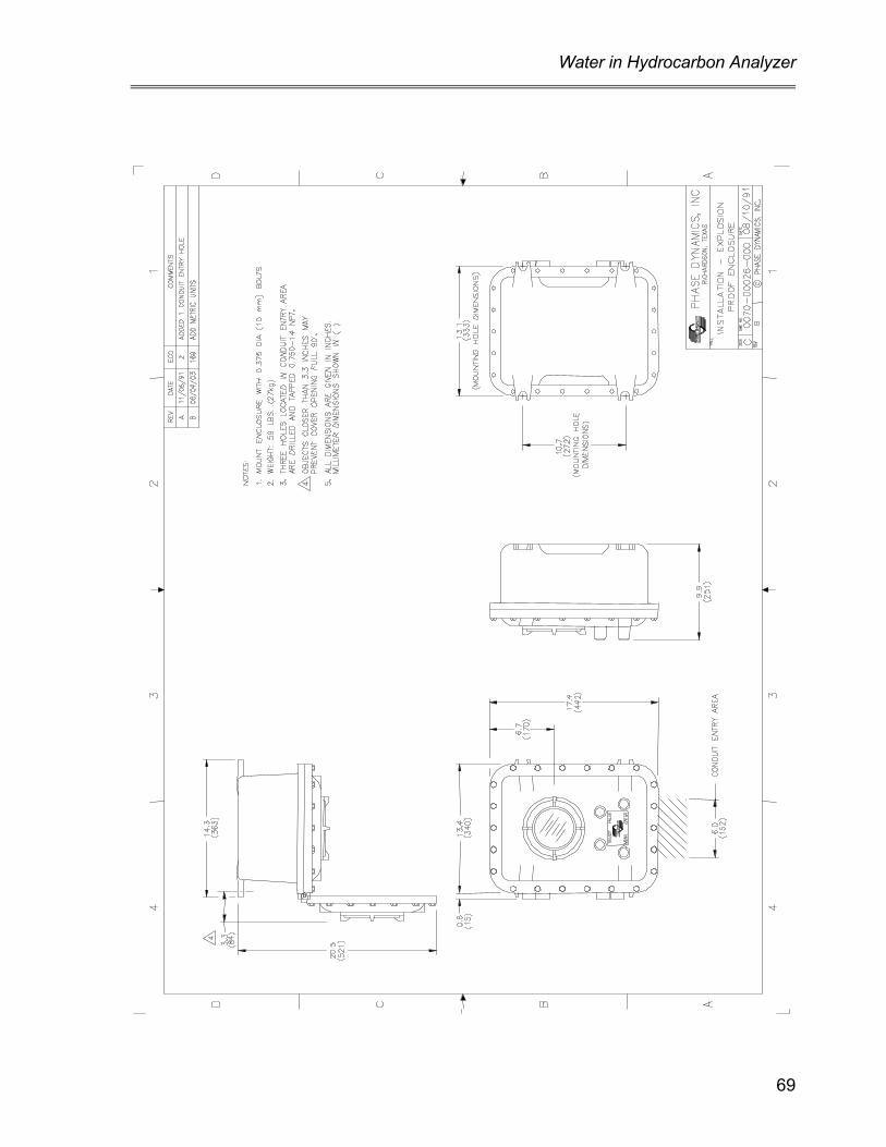
Water in Hydrocarbon Analyzer
69

PHASE DYNAMICS, INC.
70

Water in Hydrocarbon Analyzer
71

PHASE DYNAMICS, INC.
72

Water in Hydrocarbon Analyzer
73

PHASE DYNAMICS, INC.
74

Water in Hydrocarbon Analyzer
75

PHASE DYNAMICS, INC.
76

Water in Hydrocarbon Analyzer
77

PHASE DYNAMICS, INC.
78

Water in Hydrocarbon Analyzer
79

PHASE DYNAMICS, INC.
80

Water in Hydrocarbon Analyzer
81

PHASE DYNAMICS, INC.
82

Water in Hydrocarbon Analyzer
83

PHASE DYNAMICS, INC.
84

Water in Hydrocarbon Analyzer
85

PHASE DYNAMICS, INC.
86

Water in Hydrocarbon Analyzer
87

PHASE DYNAMICS, INC.
88

Water in Hydrocarbon Analyzer
89

PHASE DYNAMICS, INC.
90

Water in Hydrocarbon Analyzer
91

PHASE DYNAMICS, INC.
92

Water in Hydrocarbon Analyzer
93

PHASE DYNAMICS, INC.
94

Water in Hydrocarbon Analyzer
95

PHASE DYNAMICS, INC.
96

Water in Hydrocarbon Analyzer
97

PHASE DYNAMICS, INC.
98

Water in Hydrocarbon Analyzer
99

PHASE DYNAMICS, INC.
100

Water in Hydrocarbon Analyzer
101

PHASE DYNAMICS, INC.
102