installation 2011 civic aii 44352 cd ... - honda parts … · © 2010 american honda motor co.,...
TRANSCRIPT

Publications No.
INSTALLATIONINSTRUCTIONS
Accessory Application
© 2010 American Honda Motor Co., Inc. – All Rights Re
AII 44352
CD CHANGERserved. AII 44352 (1008
2011 CIVIC 2-DOOR
) 0
Issue Date
AUG 2010
PARTS LIST
CD Changer Attachment (Sold Separately):P/N 08B26-SVA-100
CD changer bracket
2 Side brackets
3 Clip nuts
3 EPT seals (Some may not be used.)
3 Washer-bolts
4 Flange nuts
15 Wire ties (Some may not be used.)
2 Wire ties with clip (Some may not be used.)
9 Cushion tapes
Bus cable
4 Washer screws, 4 x 8 mm
CD Changer Kit (sold separately):P/N 08A26-5E1-101
CD changer
Bracket (Not used)
8-Disc CD magazine
1 of 148B26-SVA-1001-91

8 Washer-screws, 4 x 6 mm (Not used)
Accessory User’s Information Manual
For vehicles equipped with XM radio systemBus Cable 2 Port (sold separately):P/N 08A31-0F1-000
Bus cable 2 Port
TOOLS AND SUPPLIES REQUIRED
Phillips screwdriver
Flat-tip screwdriver
Stubby Phillips screwdriver
10 mm and 14 mm Combination wrenches
Plastic Trim Tool (T/N SILTRIMTL10)
10 mm and 14 mm Sockets
Ratchet
Small flat-tip screwdriver
Isopropyl alcohol
Shop towel
Masking tape
Diagonal cutters
Ruler
2 of 14 AII 44352
Illustration of the CD Changer Installed in the Vehicle
INSTALLATION
1. Make sure you have the anti-theft codes for the audio and navigation system (if equipped), then write down the audio presets.
2. Disconnect the negative cable from the battery.
Customer Information: The information in this installation instruction is intended for use only by skilled technicians who have the proper tools, equipment, and training to correctly and safely add equipment to your vehicle. These procedures should not be attempted by “do-it-yourselfers.”
871103AH
AUDIO UNIT
BUS CABLE
CD CHANGER
(1008) © 2010 American Honda Motor Co., Inc. – All Rights Reserved.

3. Remove the passenger’s dashboard lower cover (four clips and two pins).
4. Remove the driver’s dashboard lower cover (eight clips).
871104AH
PASSENGER’S DASHBOARD LOWER COVER4 CLIPS
2 PINS
5202121T
8 CLIPS
DRIVER’S DASHBOARD LOWER COVER
© 2010 American Honda Motor Co., Inc. – All Rights Reserved. AII 44352
5. Remove the inside cover from the front console pocket (two tabs).
6. Lower the tilt lever and pull the steering wheel toward you.
7. To protect the dashboard area, place shop towels over the steering wheel and shift lever.
5202130T
FRONT CONSOLE POCKET
INSIDE COVER2 TABS
SHIFT LEVER (S POSITION)
5608031H
SHIFT LEVER
SHOP TOWEL
STEERING WHEEL
SHOP TOWEL
COMBINATION SWITCH
TILT LEVER
(1008) 3 of 14

8. Apply masking tape to the instrument panel as shown, and remove the meter panel (one self-tapping screw and 11 clips, and unplug the vehicle connector).
9. Apply masking tape to the instrument panel as shown, and remove the center panel (two bolts and 11 clips, and unplug the vehicle connectors).
871105AH
SELF-TAPPING SCREW 11 CLIPS
METER PANEL MASKING TAPE
VEHICLECONNECTOR
5202562T
VEHICLE CONNECTORS
5 CLIPS
BOLT6 CLIPS
MASKING TAPE
CENTER PANEL
4 of 14 AII 44352
10. Remove the two seat track end covers from the rear of the front passenger’s seat, then remove the two bolts that secure the seat.
871106AH
FRONT PASSENGER’S SEAT
SEAT TRACK END COVER
BOLT
(1008) © 2010 American Honda Motor Co., Inc. – All Rights Reserved.

11. Remove the center console cover:
M/T Vehicle
• Pull down on the shift boot. Remove the shift knob by turning it counterclockwise.
• Remove the center console cover by removing the five clips fastening the center console cover.
5321061H
SHIFT KNOB
SHIFT BOOT
5321072H
3 CLIPS
CENTER CONSOLE COVER
PARKING BRAKE LEVER(Pull up completely.)
2 CLIPS
© 2010 American Honda Motor Co., Inc. – All Rights Reserved. AII 44352
A/T Vehicle
Remove the center console cover (five clips).
12. Open the center console lid, and remove the mat.
13. Remove the center console (four bolts and two clips, and unplug the vehicle connector).
5202173T
3 CLIPS CENTER CONSOLE COVER
PARKING BRAKE LEVER(Pull up completely.)
SHIFT LEVER(N POSITION)
2 CLIPS
871107AH
4 BOLTS
MAT
CLIP
CENTER CONSOLE LID
VEHICLE CONNECTOR
CENTER CONSOLE
CLIP
(1008) 5 of 14

14. Inside the passenger’s compartment, remove the rear seat cushion by removing the bolt and releasing the two hooks.
15. Open the trunk lid. Fold the rear seat-back forward by pulling the levers under the rear shelf. Remove the trunk floor mat (two clips).
871108AH
BOLT
HOOK REAR SEAT CUSHION
871109AH
TRUNK FLOOR MAT
2 CLIPS
LEVERREAR SEAT-BACK
LEVER
6 of 14 AII 44352
16. Remove the trunk weatherstrip from the edge of the trunk opening in the area shown.
17. Remove the rear trim panel (two clips and three hooks).
18. Continue removing the weatherstrip in the area shown. Remove the five clips, then pull out on the trunk right side trim panel in the direction shown.
871110AH
TRUNKWEATHERSTRIP
2 CLIPS
REAR TRIM PANEL
3 HOOKS
871111AH
TRUNK RIGHT SIDE TRIM PANEL
CLIP
3 CLIPS(Turn the center pin counterclockwise
to remove.)
WEATHERSTRIP
(1008) © 2010 American Honda Motor Co., Inc. – All Rights Reserved.

Routing the bus cable
19. Route the bus cable from the trunk along the vehicle harness.
20. Lift up and lock the right rear seat-back, then remove the clip that secures the floor carpet. Pull back the floor carpet. Route the bus cable under the floor carpet as shown.
871112AHBUS CABLE
REAR SEATBACK
SEAT BRACKET
BUS CABLE
871113AH
Route under the floor carpet.
BUS CABLE
FLOOR CARPET
CLIP
© 2010 American Honda Motor Co., Inc. – All Rights Reserved. AII 44352
21. Route the bus cable forward to the right front console frame along the vehicle harness.
22. Continue routing the bus cable to the dashboard and out through the dash opening.
871114AH
DASH OPENING
DASH OPENING
BUS CABLE
BUS CABLE
VEHICLE HARNESS
(1008) 7 of 14

23. Measure 300 mm (11.8 in.) from the end of the bus cable, then secure the bus cable to the vehicle harness with four wire ties in the areas shown.
24. Along the center console area, secure the bus cable to the vehicle harness with three wire ties.
25. Using isopropyl alcohol on a shop towel, clean the areas where the cushion tape will attach. Attach the bus cable to the floor panel with the three cushion tapes in the area shown.
5222034H
BUS CABLE CONNECTOR
300 mm (11.8 in.)
BUS CABLE
WIRE TIES
871115AH
CUSHION TAPE
VEHICLE HARNESS
BUS CABLECUSHION TAPE
WIRE TIES
8 of 14 AII 44352
26. Pull back the floor carpet. Using isopropyl alcohol on a shop towel, clean the areas where the cushion tapes will attach. Attach the bus cable to the floor panel with two cushion tapes in the areas shown.
27. Secure the bus cable to the vehicle harness with three wire ties in the areas shown.
871116AH
VEHICLE HARNESS
WIRE TIES
BUS CABLE
Turn over.
BUS CABLE
CUSHION TAPE
(1008) © 2010 American Honda Motor Co., Inc. – All Rights Reserved.

28. Fold the rear seat-back forward, secure the bus cable to the vehicle harness with two wire ties in the areas shown.
29. Using isopropyl alcohol on a shop towel, clean the areas where the cushion tapes will attach. Attach the bus cable to the floor panel with three cushion tapes in the areas shown.
871117BH
CUSHION TAPE BUS CABLE
REAR SEATBACK
WIRE TIE
CUSHIONTAPE
WIRE TIE
CUSHION TAPE
VEHICLE HARNESS
© 2010 American Honda Motor Co., Inc. – All Rights Reserved. AII 44352
Installing the CD Changer
30. Using a flat-tip screwdriver, set the adjusting knobs in the horizontal (H) position.
31. Position the side brackets on the sides of the CD changer, then install the four 4 x 8 mm washer-screws.
4413031Y
(POSITION AFTER SETTING)
(FACTORY SET POSITION)
CD CHANGER
ADJUSTING KNOB
VERTICAL HORIZONTAL
5216010H
2 WASHER-SCREWS, 4 x 8 mm
SIDE BRACKETS
CD CHANGER
2 WASHER-SCREWS, 4 x 8 mm
(1008) 9 of 14

32. Position the CD changer on the CD changer bracket, then install and tighten the four flange nuts.
33. Wrap one EPT sealer around the CD changer bus cable connector, then secure the connector to the CD changer bracket with one wire tie.
871118AH
CD CHANGER
CD CHANGER BRACKET
4 FLANGE NUTS
871119AH
CD CHANGER BRACKET
CD CHANGER
WIRE TIE
EPT SEALERCD CHANGER BUS CABLE CONNECTOR
10 of 14 AII 44352
34. In the trunk, slide the clip nut into position on the rear seat panel through the hole in the panel. If necessary, spread the clip nut open with a small flat-tip screwdriver.
35. Loosely install the washer-bolt to the rear seat panel first. Then, place the end of the CD changer bracket between the seat panel and clip nut you just installed.
871120AH
CLIP NUT
WASHER-BOLT
CD CHANGER
CD CHANGER BRACKET(Place the end of the bracket between the seat panel and clip nut you just installed.)
(1008) © 2010 American Honda Motor Co., Inc. – All Rights Reserved.

36. Slide the two clip nuts onto the CD changer bracket and rear shelf through the holes in the rear shelf, and align their holes as shown. Install the two washer-bolts and tighten them securely.
871121AH
CD CHANGER BRACKET
WASHER-BOLTS
CD CHANGER BRACKET
CLIP NUTS
CLIP NUT
REAR SHELF
© 2010 American Honda Motor Co., Inc. – All Rights Reserved. AII 44352
37. Plug the bus cable connector to the connector on the CD changer.
38. Using isopropyl alcohol on a shop towel, clean the area where the cushion tape will attach. Attach the bus cable to the rear seat panel with one cushion tape.
871123AH
BUS CABLE
BUS CABLE CONNECTOR
CUSHION TAPE
CD CHANGER
CD CHANGER CONNECTOR
REAR SEAT PANEL
(1008) 11 of 14

39. Fold the excess bus cable, and secure the bus cable to the holes in the rear seat panel with two wire ties with clip.
871124AH
CD CHANGER
REAR SEAT PANEL
BUS CABLE(Fold the excess cable.)
WIRE TIE WITH CLIP
12 of 14 AII 44352
If the vehicle you’re working on is equipped with XM radio, continue with step 40; otherwise, go to step 42.
40. Plug the bus cable 2 port connectors to the two bus cables.
41. Wrap the two connectors with two EPT sealers.
871125AH
BUS CABLE 2 PORT
2 BUS CABLES
EPT SEALER
EPT SEALER
(1008) © 2010 American Honda Motor Co., Inc. – All Rights Reserved.

42. Plug the bus cable connector into the rear of the head unit.
Standard Audio Unit
Multi Control CD Tuner Unit
5801010H
BUS CABLE or BUS CABLE 2 PORT
AUDIO UNIT
871126AH
CD TUNER
BUS CABLE or BUS CABLE 2 PORT
© 2010 American Honda Motor Co., Inc. – All Rights Reserved. AII 44352
CD Tuner with Cassette Player
CD Tuner with Media Player
871127AH
CD TUNER
PLAYER
BUS CABLE or BUS CABLE 2 PORT
871128AH
CD TUNER
PLAYER
BUS CABLE or BUS CABLE 2 PORT
(1008) 13 of 14
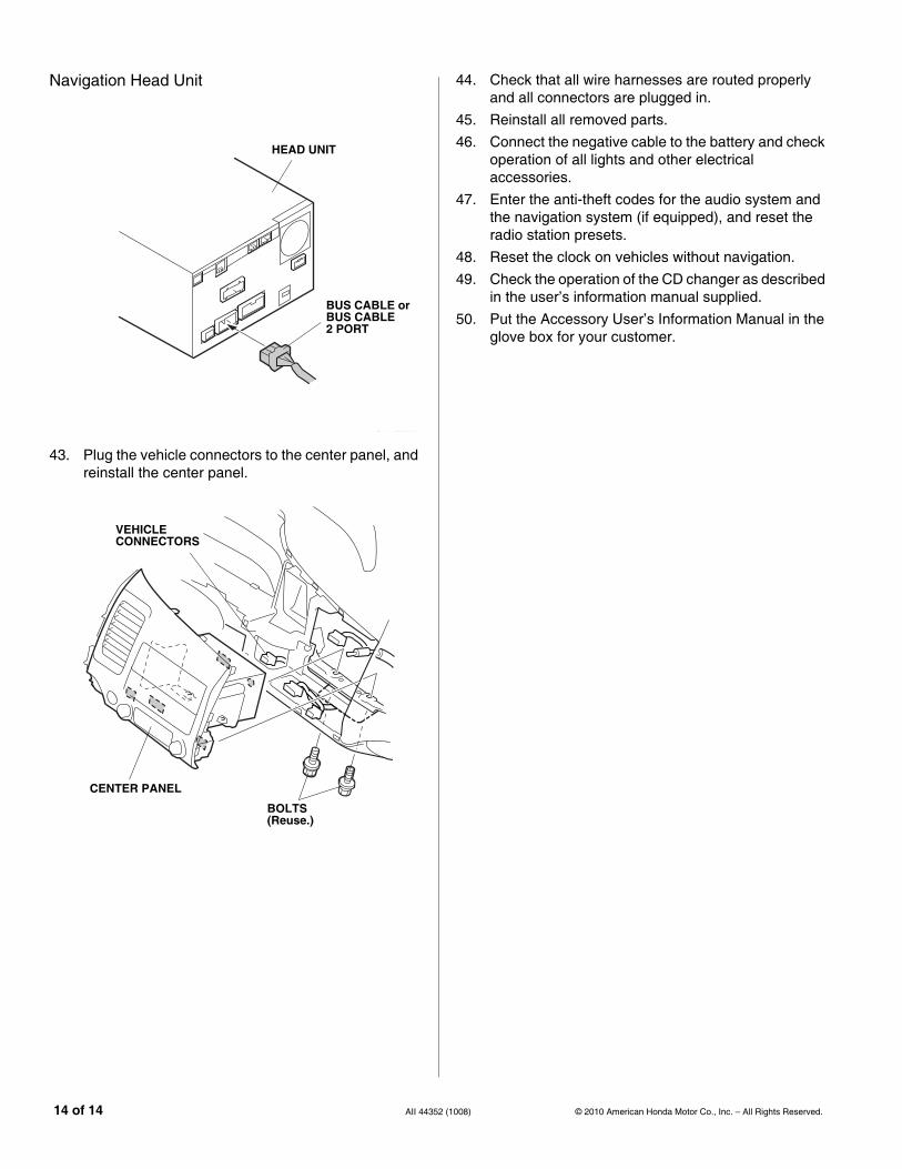
Navigation Head Unit
43. Plug the vehicle connectors to the center panel, and reinstall the center panel.
871129AH
HEAD UNIT
BUS CABLE or BUS CABLE 2 PORT
871130AH
CENTER PANEL
BOLTS(Reuse.)
VEHICLECONNECTORS
14 of 14 AII 44352
44. Check that all wire harnesses are routed properly and all connectors are plugged in.
45. Reinstall all removed parts.
46. Connect the negative cable to the battery and check operation of all lights and other electrical accessories.
47. Enter the anti-theft codes for the audio system and the navigation system (if equipped), and reset the radio station presets.
48. Reset the clock on vehicles without navigation.
49. Check the operation of the CD changer as described in the user’s information manual supplied.
50. Put the Accessory User’s Information Manual in the glove box for your customer.
(1008) © 2010 American Honda Motor Co., Inc. – All Rights Reserved.