installatin insttins
TRANSCRIPT

- 1 -
INSTALLATION INSTRUCTIONS
SA
VE
F
OR
F
UT
UR
E
US
E
Product names listed herein are trademarks of AS America, Inc.© AS America, Inc. 2017 M965858 (10/17)
RECOMMENDED TOOLS AND MATERIALSMost of the procedures require the use of common tools and materials, which are available from hardware and plumbing supply stores. It is essential that the tools and materials be on hand before work has begun.
ROUGHING-IN DIMENSIONS: • Connections are: 1/2" NPT
D35005533.191/D35005533S.191 Rough Valve Body OnlyWith built-in 2-way diverter
3-Handle ThermostaticRough with 2-Way DiverterModels: D35005533.191 / D35005533S.191
* If designated with an “S”, the valve offers shared flow position between adjacent outlets.
For use with shower heads rated at 9.46 L/min (2.50 gpm) or higher.
Thank you for selecting DXV. To ensure that your installation proceeds smoothly, please read these instructions carefully before you begin.
1/2" NPT.MALE
3-3/4"(96 mm)
3-7/8"(98 mm)
4"(102 mm)
4"(102 mm)
HOTINLET
COLDINLET 11-5/16"
(287 mm)
FINISHED WALL
5-1/16"(129 mm)
4- 7/8"(124 mm)
1-15/16"(49 mm)
9/16"(14 mm)
3/4" NPT.FEMALE
3/4" NPT.
FEMALE
3/4" NPT.FEMALE
1/2" NPT.MALE
4-1/4" MIN. TO 5-1/8" MAX.(108 TO 130 mm)
Adjustable Wrench Te�on TapeChannel Locks Tubing CutterFlat Blade Screwdriver
(provided)
- 2 -
1
2
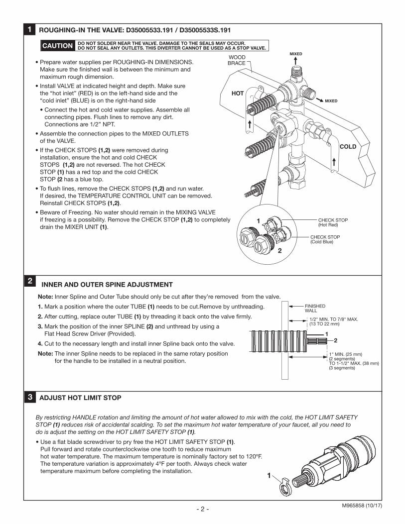
ROUGHING-IN THE VALVE: D35005533.191 / D35005533S.191
• Prepare water supplies per ROUGHING-IN DIMENSIONS. Make sure the finished wall is between the minimum and maximum rough dimension.
• Install VALVE at indicated height and depth. Make sure the “hot inlet” (RED) is on the left-hand side and the “cold inlet” (BLUE) is on the right-hand side
• Connect the hot and cold water supplies. Assemble all connecting pipes. Flush lines to remove any dirt. Connections are 1/2” NPT.
• Assemble the connection pipes to the MIXED OUTLETS of the VALVE.
• If the CHECK STOPS (1,2) were removed during installation, ensure the hot and cold CHECK STOPS (1,2) are not reversed. The hot CHECK STOP (1) has a red top and the cold CHECK STOP (2 has a blue top.
• To flush lines, remove the CHECK STOPS (1,2) and run water. If desired, the TEMPERATURE CONTROL UNIT can be removed. Reinstall CHECK STOPS (1,2).
• Beware of Freezing. No water should remain in the MIXING VALVE if freezing is a possibility. Remove the CHECK STOP (1,2) to completely drain the MIXER UNIT (1).
M965858 (10/17)
CAUTION DO NOT SOLDER NEAR THE VALVE. DAMAGE TO THE SEALS MAY OCCUR. DO NOT SEAL ANY OUTLETS. THIS DIVERTER CANNOT BE USED AS A STOP VALVE.
COLD
HOT
WOODBRACE
MIXED
MIXED
1
2
CHECK STOP(Hot Red)
CHECK STOP(Cold Blue)
Note: Inner Spline and Outer Tube should only be cut after they’re removed from the valve.
1. Mark a position where the outer TUBE (1) needs to be cut.Remove by unthreading.
2. After cutting, replace outer TUBE (1) by threading it back onto the valve firmly.
3. Mark the position of the inner SPLINE (2) and unthread by using a Flat Head Screw Driver (Provided).
4. Cut to the necessary length and install inner Spline back onto the valve.
Note: The inner Spline needs to be replaced in the same rotary position for the handle to be installed in a neutral position.
INNER AND OUTER SPINE ADJUSTMENT
FINISHED WALL
12
1/2" MIN. TO 7/8" MAX.(13 TO 22 mm)
1" MIN. (25 mm)(2 segments)TO 1-1/2" MAX. (38 mm)(3 segments)
3 ADJUST HOT LIMIT STOP
By restricting HANDLE rotation and limiting the amount of hot water allowed to mix with the cold, the HOT LIMIT SAFETY STOP (1) reduces risk of accidental scalding. To set the maximum hot water temperature of your faucet, all you need to do is adjust the setting on the HOT LIMIT SAFETY STOP (1).
• Use a flat blade screwdriver to pry free the HOT LIMIT SAFETY STOP (1). Pull forward and rotate counterclockwise one tooth to reduce maximum hot water temperature. The maximum temperature is nominally factory set to 120ºF. The temperature variation is approximately 4ºF per tooth. Always check water temperature maximum before completing the installation.
1

- 3 -M965858 (10/17)
In the United States:DXVOne Centennial Avenue Piscataway, New Jersey 08855Attention: Director of Customer Care
For residents of the United States, warranty information may also be obtained by calling the following toll free number: (800) 227-2734www.DXV.com
In Canada:DXV 5900 Avebury Road Mississauga, Ontario L5R 3M3 Canada
Toll Free: 1-800-387-0369Local: 905-306-1093 Fax: 1-800-395-1498 www.DXV.ca
In Mexico:DXV Via Morelos 330 Col. Santa Clara Coatitla Ecatepec, Estado de México 55540
Toll Free: 01-800-8391200www.DXV.mx
MODEL NUMBERS
3-Handle Thermostatic Rough with 3-Way Diverter
D35005533.191D35005533S.191
5
4
6
8-D350055338a-D35005533S
9
2
7
1
3
1 M970414-0070A VOLUME CONTROL CARTRIDGE
2 M970403-0070A HANDLE EXTENSION FOR DIVERTER
3 M970415-0070A THERMO CARTRIDGE
4 M970410-0070A CARTRIDGE NUT
5 M970409-0070A HANDLE EXTENSION FOR THERMO
6 M970417-0070A CHECK VALVE KIT
7 M970418-0070A CHECK STOP KIT
8 M970419-0070A CARTRIDGE FOR DIVERTER (Non Shared)
8a M970420-0070A CARTRIDGE FOR DIVERTER (Shared)
9 M970412-0070A NUT CAP FOR DIVERTER