instability wave control in turbulent jet by acoustical ... · flow control figure 2 arti¦cial...
TRANSCRIPT
INSTABILITY WAVE CONTROL IN TURBULENTJET BY ACOUSTICAL AND PLASMA ACTUATORS
V.F. Kopiev1, I. V. Belyaev1, G.A. Faranosov1,V.A. Kopiev1, N.N. Ostrikov1, M.Yu. Zaytsev1,Yu. S. Akishev2, M. E. Grushin2, N. I. Trushkin2,
V.A. Bityurin3, A. I. Klimov3, I. A. Moralev3, I. A. Kossyi4,N.K. Berezhetskaya4, and M. I. Taktakishvili4
1Central Aerohydrodynamics Institute (TsAGI)17 Radio Str., Moscow 105005, Russia
2Troitsk Institute for Innovation and Fusion Research (TRINITI)12 Pushkovykh Str., Troitsk 142190, Moscow Region, Russia
3Joint Institute for High TemperaturesRussian Academy of Sciences
13-2 Izhorskaya Str., Moscow 125412, Russia4General Physics Institute
Russian Academy of Sciences38 Vavilova Str., Moscow 119991, Russia
It was recently demonstrated by direct experiment in subsonic jets thatan instability wave in jet shear layer generated by pure-tone acoustic ex-citation could be suppressed by another acoustic excitation, which gener-ates an instability wave with the same properties. It was suggested thatinstability waves could be generated by any oscillating ¦eld near the noz-zle exit. This paper presents the results of experimental investigations ofinstability wave suppression by other types of periodic excitation. Threetypes of plasma actuators are considered: (i) high-frequency (HF) dielec-tric barrier discharge (DBD); (ii) slipping discharge; and (iii) coronadischarge. Control authority of the plasma actuators over instabilitywaves is demonstrated. For high-speed hot jets where instability wavesare the dominant noise source, instability wave control is equivalent tonoise control.
1 INTRODUCTION
The paper deals with the problem of instability wave control in turbulent jets.Noise of a turbulent jet issuing from a jet engine nozzle still remains an im-
Progress in Flight Physics 7 (2015) 211-228 DOI: 10.1051/eucass/201507211 © Owned by the authors, published by EDP Sciences, 2015
This is an Open Access article distributed under the terms of the Creative Commons Attribution License 4.0, which permits unrestricted use, distribution, and reproduction in any medium, provided the original work is properly cited.
Article available at http://www.eucass-proceedings.eu or http://dx.doi.org/10.1051/eucass/201507211
PROGRESS IN FLIGHT PHYSICS
portant source of community noise due to civil aircraft. A promising way toreduce jet noise consists in development of active noise control systems [1�3].The main problems with this idea are related to the lack of understanding of jetnoise mechanisms, which could be acted upon by the active closed-loop controlsystem. One of the best understood mechanisms from the standpoint of theo-retical description and, hence, most convenient for designing active noise controlsystems is the mechanism of sound radiation by instability waves that is realizedin high-speed jets [4�8].
Although instability waves are also present in low-speed jets, they do notradiate sound directly. Nevertheless, instability wave development at the ini-tial part of the shear layer is essentially the same both for low- and high-speed(including supersonic) jets [4,7]. This implies that successful realization of insta-bility wave control in low-speed jets, which are more convenient for experimentalinvestigation, will con¦rm the possibility of noise control in jets of technologicalinterest.
In [9, 10], the possibility of active instability wave control was theoreti-cally studied within the framework of relatively simple model problems. It hasbeen shown that the instability wave excited by time-harmonic action with fre-
quency ω can be suppressed by a plane
Figure 1 Integration contour onthe complex plane α
acoustic wave with properly chosen ampli-tude and phase.
Indeed, from the mathematical point ofview, the instability wave excited in a jetby any kind of (small) time harmonic ac-tion (e. g., acoustic excitation) correspondsto pole α0 of the dispersion relation of thesystem (mean §ow) [11]. For any type oftime-harmonic action with frequency ω, thesolution for the jet response to the actioncontains two di¨erent parts: the di¨raction
part related to the integral over real wave-numbers (in terms of inverse Fouriertransform) and the hydrodynamic part, i. e., instability wave, associated withthe residue at the instability pole α0 (Fig. 1); the spatial structure of the hy-drodynamic part is thus independent of the way of excitation. Therefore, if aninstability wave is excited, it could be suppressed by any other type of excitation,e. g., due to plasma actuators (Fig. 2). Thus, the idea of instability wave controlseems quite realizable in theory.
The present paper is devoted to experimental investigation of the feasibilityto suppress arti¦cial excited instability wave by means of acoustic as well asplasma actuators. It should be noted that the case in point is the suppressionof the hydrodynamic (instability) part of the ¦eld, while the remaining acousticpart in general does not vanish and represents a linear combination of the twodi¨erent di¨racted acoustic ¦elds.
212

FLOW CONTROL
Figure 2 Arti¦cial instability wave generated by an acoustic sound driver located inthe stilling chamber (a) and plasma actuators generating the instability wave with theopposite phase (b)
2 EXPERIMENTAL SETUP
The experiments were carried out in anechoic chamber AC-2 of TsAGI. Theambient air is compressed and stored in 22 cylindrical tanks at a pressure of upto 22 MPa with a capacity of 9 m3. Jet velocity reached 300 m/s for a nozzlediameter of 5 cm. The experiments have been carried out for two jet velocities:100 and 200 m/s (Reynolds number based on the jet diameter was up to 8.3·105).Turbulent velocity §uctuations in the jet potential core were about 1%.The major experimental tool for instability wave diagnostics in excited jets
was two-dimensional (2D) Time-Resolved Particle Image Velocimeter (TR PIV)with the integrated software�hardware system FlowMaster HS-PIV byLaVision c©. This measurement system can provide quantitative measurementsof the instantaneous §ow velocity ¦eld of turbulent §ows with high spatial andtemporal (up to 10 kHz) resolution. The main components and capabilities ofFlowMaster are as follows:
� Nd:YAG double-cavity Laser: wavelength 532 nm, pulse energy 2×22.5 mJat 1000 Hz, maximum pulse frequency 2× 10 kHz;
� Digital camera HighSpeedStar 8 with CMOS (complementary metal�oxide�semiconductor) matrix 1024 × 1024, sampling frequency 7500 fpsat full resolution, dynamic range 12 bit, memory 8 Gb;
� Synchronization module HSC Controller with pulse generator for PIV;
� Light sheet optics with light-guide manipulator Laser Guiding Arm;
� 2D PIV Software package: DaVis 8, 2D PIV High-Speed Data Analysis;
� Large Seeding Device (40 jets, for high mass §ow rates). Seeding liquidDEHS (Di-2-Ethylhexyl-Sebacat), particle diameter 1 µm; and
� GPU (Graphics Processing Unit) for acceleration of PIV postprocessing.
213

PROGRESS IN FLIGHT PHYSICS
The plane of measurement and, thus, the laser sheet were ¦xed along the jetaxis. The measurement area had dimensions 300×300 mm. This square area wasvertically centered on the jet axis. With this setup, it was intended to measuredevelopment of coherent structures up to 6 nozzle diameters downstream. ThePIV image processing was performed with a multipass interrogation window al-gorithm (DaVis 8) with ¦nal interrogation window 16× 16 pixel and 50 percentoverlapping. Two adjacent velocity vectors were, thus, separated by approxi-mately 2 mm.
2.1 Instability Wave Identi¦cation for an Acoustic and PlasmaForced Jet with Time-Resolved Particle Image Velocimeter
For quantitative diagnostics of arti¦cially excited coherent structures/instabilitywaves in jets, phase-locked PIV has been used. The method is similar to strobo-scopic PIV utilized by Schram et al. [12] for investigation of sound ¦eld generatedby vortex pairing in a subsonic jet. The principal idea of phase-locked PIV con-sists in averaging PIV results over a sequence of images with the same phaseshift relative to the excitation signal. This allows to separate a periodic (intime) component of velocity ¦eld from uncorrelated pulsations. For the purposeof coherent structure identi¦cation, a speci¦c value of this phase shift is of littleinterest because it is well known from schlieren visualization [13] that strobo-scopic visualization with frequency multiple to the excitation signal frequencyprovides a ¢frozen£ picture of coherent structures in a jet for any phase shift dueto the e¨ect of optical averaging. Therefore, PIV measurements have been per-formed without prescribing this phase shift and, thus, without using a triggeringsignal from the acoustic excitation; the only requirement was that the excitationfrequency has to be equal to the TR PIV frame rate.
2.1.1 Acoustic excitation
The TR PIV technique has been applied to an experimental study of high-speedturbulent jets issuing with a velocity of 300 m/s from a conical nozzle with an exitdiameter of 50 mm. Arti¦cial instability waves were generated by a loudspeakeroperating at a discrete frequency and located at ∼ 1.5 m upstream the nozzleexit. The stability of excitation frequency has been controlled with 1/2-inchmicrophone B&K 4189C in the far-¦eld and the data acquisition and analyzingsystem B&K Pulse 3560D with an accuracy of 1 Hz.
Typical scalar ¦elds of Vx (velocity component along the jet direction) and Vy
(velocity component normal to the jet direction) obtained in the longitudinalcross section of the jet by averaging a sequence of 300 instantaneous maps arepresented in Fig. 3 (here and below, nozzle exit center is located at point (0;0)).
214

FLOW CONTROL
Figure 3 Average Vx (a) and Vy (b) velocity ¦elds for unforced jet. The blackgeometrical mask is somewhat larger than the nozzle, which exit is located at x = 0 mm
The results of phase-locked
Figure 4 The PIV-measured wavepacket inthe jet shear layer
PIV measurements presented inFigs. 4 and 5 demonstrate the ap-pearance of periodic spatial struc-tures (particularly, in Fig. 5b forVy ¦eld) which can be associatedwith the most excited instabilitywave for this high-speed jet. Inthe case of mismatch betweenacoustical excitation frequency(e. g., 3 kHz) and PIV samplingfrequency (e. g., 3.72 kHz), the or-derly structure of velocity ¦eldwere found to disappear, so thatthe §ow picture looks like that for the unforced jet (see Fig. 3). Thus, the ex-perimental method is e¨ective and can be used for identi¦cation and analyses ofinstability waves.
2.1.2 Plasma actuators for instability waves excitation
Similar tests have been carried out for the jet excited by electric discharges.For instability wave control in the jet shear layer near to the nozzle exit, sev-eral plasma actuators were developed and manufactured. These actuators are
215

PROGRESS IN FLIGHT PHYSICS
Figure 5 Velocity ¦elds Vx (a) and Vy (b) for the jet, acoustically forced at a frequencyof 3000 Hz; sampling rate is 3000 fps
based on di¨erent types of gas discharges (HF DBD, high-current slipping surfacedischarge, surface barrier corona discharge). For comparability of the receivedresults, identical ceramic nozzles (Fig. 6) with Witoszynski pro¦le (exit diameter50 mm) were used for all actuators.
Below, plasma actuator models for instability wave excitation in turbulentjet shear layer will be presented.
Figure 6 Ceramic nozzles for di¨er-ent types of plasma actuators
Figure 7 The HF DBD plasma actuatorin anechoic chamber AC-2
216

FLOW CONTROL
2.2 High-Frequency Dielectric Barrier Discharge Plasma Actuator
The ¦rst actuator uses the classical two-electrode surface DBD scheme [14]. Forits operation, a high-voltage, HF power supply was used, which has the frequencyrange up to 300 kHz. Circular electrodes made of aluminum bands were gluedon the inner surface of the nozzle (Fig. 7). The external electrode is completelycovered with dielectric (silicone compound), which prevented plasma generationon the external nozzle surface while supplying the voltage up to 20 kV to theelectrodes. The internal plasma-generating electrode is located at a distanceof 5 cm upstream from the nozzle exit. The discharge develops in the downstreamdirection.Electrical parameters of the plasma actuator power supply, designed and built
in-house, are as follows:
� high voltage ¡ up to 20 kV;
� oscillation frequency ¡ within 100�300 kHz;
� modulation frequency ¡ up to 20 kHz;
� modulation depth ¡ 100%; and
� power ¡ up to 1 kW.
2.3 Barrier Corona Discharge Plasma Actuator
The barrier corona discharge plasma actuator
Figure 8 The sketch of the elec-trode con¦guration of the single-disk plasma actuator: 1 ¡ quartzdisk; 2 ¡ 36 needle electrodes;3 ¡ HV electrode; and 4 ¡ alu-minum foil covering the oppositeside of the disk (grounded elec-trode)
allows one to take basic advantages from bothcorona discharge and DBD [15]. Such dis-charge combination enables the distance be-tween neighboring needles (pins) to be drasti-cally diminished without giving rise to sparkformation. Besides, this design allows unlim-ited scaling in the transverse direction and en-ables generation of transverse uniform electricwind.The sketch of the electrode con¦guration of
a single-disk actuator based on the sectionedDBD surface corona discharge is shown inFig. 8. External diameter of the disk is equalto 151 mm, internal diameter is 60 mm, andthickness of the disk is 3.5 mm. The disk ismade of quartz. There are 36 needle high-voltage (HV) electrodes uniformly distributedover the disk perimeter and connected toa single HV electrode. On the other-side of
217

PROGRESS IN FLIGHT PHYSICS
Figure 9 The images of the disk actuator at operating conditions with switched-on barrier corona discharge: (a) the plasma actuator with a single disk; and (b) thedual-disk plasma actuator in anechoic chamber AC-2 of TsAGI
the disk, there is a disk-shaped grounded electrode. The dual-disk plasma ac-tuator consists of two single-disk actuators, which are coaxial and placed face-to-face. The gap between disks in the dual-disk actuator equals to 2.5 mm (thisdistance can be varied). The position of plasma actuator at the nozzle edge canbe also varied (Fig. 9).The photos of the single disk plasma actuator in operating conditions and
the dual-disk plasma actuator are shown in Figs. 9a and 9b, respectively. Theactuator is installed on the Witoszynski nozzle in AC-2 anechoic chamber ofTsAGI.This electric discharge was created by the HV generator (designed and built
in-house) with the following pulse parameters:
� high voltage ¡ up to 10 kV;
� oscillation frequency ¡ 100 kHz;
� modulation frequency ¡ up to 1 kHz;
� modulation depth ¡ 100%; and
� power ¡ < 0.6 kW.
2.4 Slipping Surface Discharge Plasma Actuator
The slipping surface discharge actuator is shown schematically in Fig. 10.This discharger consists of a sequence of electrodes and interelectrode gaps
located on the outer surface of a §at or cylindrical dielectric base. All electrodeswith the exception of two boundary ones (the ¦rst and the last) are under the¢§oating£ potential.
218

FLOW CONTROL
Figure 10 Scheme of the multielectrode discharge actuator: 1 ¡ metallic electrodes(E1, E2, . . . , En); 2 ¡ dielectric base; 3 ¡ back-current conductor; and 4 ¡ dischargeplasma
Dischargers are made in such a way that a high-voltage pulse is initially ap-plied to the ¦rst interelectrode gap. After the breakdown in this gap and plasmaformation that shorts out the ¦rst interelectrode gap, almost entire voltage isapplied to the next (second) gap and so on up to the last one. By such means, itis possible to short out with the relatively small voltage an unusually long multi-electrode line. To realize this, the con¦guration of elements and their materialsshould be chosen in such a way that a relation C1n/C2n ≫ 1 has to be satis¦edfor the distributed capacities of discharger constructive elements (here, C1n andC2n are the distributed capacities between the neighbor electrodes and betweenelectrodes and the back-current conductor, respectively). This discharge wasdescribed elsewhere [16].Slipping surface discharge plasma actuator has eight plasma forming spark
gaps on the inner nozzle surface at 1-centimeter distance upstream from thenozzle edge (Fig. 11).
Figure 11 Photo of the actuator assembled on the ceramic nozzle (a) and its electricalschematic diagram (b): 1 ¡ dielectric nozzle; 2 ¡ electrodes; 3 ¡ capacities C2n; and4 ¡ HV pulse
219

PROGRESS IN FLIGHT PHYSICS
This electric discharge was created by the custom-built HV pulse generatorwith the following pulse parameters:
� mean power ¡ < 0.3 kW;
� voltage ¡ 10�20 kV;
� pulse duration ¡ ∼ 1 µs;� pulse current ¡ 100�200 á; and
� pulse repetition rate ¡ 1�1000 Hz.
The energy deposition was about ∼ 0.05 J in one discharge pulse.Results of phase-locked PIV measurements demonstrate the capability of
these three plasma actuators (based on HF DBD, on barrier corona discharge,and on multispark slipping surface discharge) to create periodic spatial structure,which can be associated with the most excited instability wave for high-speedjets. Plasma-excited instability wave parameters were close to those that wereobtained for acoustic excitation. These plasma actuators were used in the ex-periments on instability wave control.
3 EXPERIMENTAL VERIFICATIONOF THE FEASIBILITY TO CONTROLTHE ARTIFICIALLY EXITED INSTABILITY WAVEBY EXTERNAL ACOUSTIC ACTION
The main objective of the experiment described below was to demonstrate thefeasibility to control arti¦cially excited instability waves in turbulent jets. TheTR PIV diagnostic technique described in the previous section was used in theexperiments. The idea of the experiment is based on the theory of acoustic in-stability wave control described in [10, 17]. In these papers, the instability waveis excited by a plane acoustic wave coming from semiin¦nite cylindrical nozzle,and then this instability wave is cancelled by an external acoustic wave withproperly chosen amplitude and phase according to the analytical solution of thecontrol problem. The main result of the developed theory consists in justi¦cationof the possibility of e¨ective control over arti¦cial instability wave by means ofan external action with the amplitude of the same order as the internal one. Itshould be emphasized here that it is fundamentally important that inner andouter excitations of the jet are considered, since otherwise, e. g., in the case ofinner�inner excitation, the problem would reduce to the trivial acoustic cancella-tion inside the duct, whereas in the case of inner and outer excitations, acoustic¦elds are not canceled, while the Kelvin�Helmholtz instability is canceled.In order to test experimentally the possibility of shear layer instability control
which has been shown to be realizable theoretically, ¦rst, axisymmetric external
220

FLOW CONTROL
Figure 12 Experimental setup; (a) photo in AC-2; and (b) sketch of the setup: 1 ¡PIV camera; 2 ¡ acoustic concentrator; 3 ¡ hot-wire probe; 4 ¡ nozzle; 5 ¡ outerloudspeaker; and 6 ¡ far-¦eld microphone. Dimensions are in millimeters
and internal acoustic excitations of the jet should be provided for generationof a mainly axisymmetric instability (zero mode) that is close to the modelproblem considered theoretically. Axisymmetric internal excitation was createdby a loudspeaker located in the settling chamber at a distance of about 1.5 mupstream from the nozzle exit, the diameter of the nozzle was 52 mm. Sucha con¦guration was tested to provide azimuthally uniform near- and far-¦eld atthe frequency of excitation with an error less than ±0.5 dB. Excitation of anaxisymmetric external acoustic wave near the nozzle exit with the amplitudecomparable to the internal one turned out to be a more complicated problem.It was resolved by making use of a metal truncated cone aligned with the jetaxis and forming a quasi-annular duct around the main nozzle (Fig. 12). Theback surface of the cone was closed by a special ring cover with two loudspeakersinserted in it. The exit plane of the cone was coplanar to the main nozzle exit.This system of external excitation provided azimuthal uniformity of the near¦eld with an error of ±0.9 dB. Azimuthal structure of the ¦eld was measured by6 microphones located symmetrically near the front edge of the cone. These mi-crophones were removed during the main measurements performed with 50 m/sjet excited at 1 kHz (Strouhal number St = 1.04).The measurements were conducted in two stages. During the ¦rst stage,
a far-¦eld microphone and a hot-wire probe were used (see Fig. 12). The 1/2-inch 4189C Bruel&Kjaer microphone was located in the far ¦eld at a distanceof 2 m from the nozzle exit center at an angle of 30◦ to the jet axis, and theDantec 55P01 hot-wire probe was placed approximately in the middle of theshear layer 100 mm downstream from the nozzle exit plane. During the secondstage, the hot-wire probe was removed and PIV measurements of the excited jetwere performed.The microphone and hotwire measurements showed that provided the inter-
nal and external excitations are adjusted in the proper way, one can e¨ectively
221

PROGRESS IN FLIGHT PHYSICS
Figure 13 Radial velocity ¦eld (Vy) for the phase shifts corresponding to maximalampli¦cation (a) and maximal attenuation (b) of the instability in the jet shear layer
amplify or attenuate hydrodynamic coherent structures in the jet just by varyingthe phase shift between the sources of excitation.
However, these measurements pertain to one point where the hot-wire probeis located and, thus, they do not preclude the possibility that change in themeasured amplitude is not due to suppression/ampli¦cation of instability wavebut rather due to shift of the nodes of instability wave. To ensure that theamplitude of instability waves does indeed change in the entire shear layer, phase-lock PIV measurements were carried out. These measurements were performedat an excitation frequency of 1 kHz, the PIV sampling frequency being the same
(1 kHz) in accordance with the pro-
Figure 14 Radial velocity (Vy) pro¦lesalong the lip-line for the regimes presentedin Fig. 13
cedure described above. The micro-phone was removed. The source am-plitudes were adjusted by means ofhot-wire measurements, then thehotwire probe was also removed fromthe jet and phase-lock PIV measure-ments were carried out for di¨erentphase shifts between the internal andexternal sources (with step 30◦). Theevolution of coherent structures ob-served after PIVmeasurements post-processing (its parameters were thea same as in a previous section) is
222
FLOW CONTROL
presented in Fig. 13, where one can see radial velocity ¦eld (Vy) for the phaseshifts corresponding to the maximal ampli¦cation and maximal attenuation ofinstability waves. Let notice that these shifts di¨er by 180◦.In Fig. 14, one can see the pro¦les of radial velocity (Vy) along the lip-line for
the regimes presented in Fig. 13. It is seen from Fig. 14 that in the conductedexperiment, a ¦vefold variation in shear layer instability amplitude takes place.It should be emphasized that it does not seem to matter what particular type ofaction is used for generation of instability wave. In the described experiment, itwas created by an acoustic excitation, but equally well it could be produced byany other actuator.
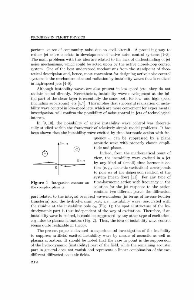
4 EXPERIMENTAL VERIFICATIONOF THE POSSIBILITY TO CONTROL ARTIFICIALINSTABILITY WAVE BY PLASMA ACTUATORS
In the experiments described in this section, plasma actuators have been usedinstead of external acoustic waves. A sketch of the instability wave controlexperiments is depicted in Fig. 15.In this scheme, the 2D TR PIV system described above was also used. Again,
the experiments were carried out in anechoic chamber AC-2 of TsAGI. First, theintensities of acoustical and plasma excitation were adjusted so as to give ap-proximately equal levels of instability wave amplitude. For this adjustment,PIV measurements of the amplitude of instability wave generated by the plasmaactuator and the loudspeaker have been performed separately. After the acous-tical and plasma excitations were adjusted independently to the same level, theywere turned on simultaneously with controllable phase shift –ϕ between them.
Figure 15 Sketch of instability wave control experiments with plasma actuators
223

PROGRESS IN FLIGHT PHYSICS
Variation of the phase shift led to variations of the instability wave amplitudemeasured by phase-lock TR PIV.
The experiments were performed with three types of plasma actuators de-scribed above, the jet with a velocity of 100 m/s was excited at a frequencyof 1 kHz. With the HF DBD actuator, the experiments were also performed for200 m/s jet excited at a frequency of 2 kHz. For all these cases, Strouhal numberwas 0.5 because a particular choice of excitation frequency is of little importancein this study and it was deemed convenient to choose a frequency near the max-
Figure 16 Combined excitation by the HF DBD plasma actuator and the loud-speaker. The radial velocity ¦eld (Vy) for phase shifts corresponding to maximal am-pli¦cation (left column) and maximal attenuation (right column) of the instability wavein the jet shear layer: (a) jet velocity 100 m/s, excitation frequency 1 kHz; and (b) jetvelocity 200 m/s, excitation frequency 2 kHz
224
FLOW CONTROL
imum of jet noise spectrum. The same refers to the choice of azimuthal modem = 0. Nevertheless, it is worth noting that a study of higher azimuthal modesis of undoubted interest and is going to be carried out in future after appropriateupgrade of the plasma actuators power supply.
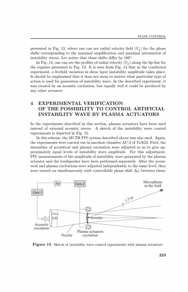
Evolution of coherent structures measured by PIV is shown in Figs. 16 and 17,which depict Vy velocity ¦elds under the combined action of the loudspeaker anddi¨erent plasma actuators for two phase shifts between them corresponding to
Figure 17 Combined excitation by the barrier corona discharge plasma actuatorand the loudspeaker (a) and by the slipping surface discharge plasma actuator and theloadspeaker (b). The radial velocity ¦eld (Vy) for phase shifts corresponding to maximalampli¦cation (left column) and maximal attenuation (right column) of the instabilitywave in the jet shear layer. Jet velocity 100 m/s, excitation frequency 1 kHz
225

PROGRESS IN FLIGHT PHYSICS
Figure 18 Radial velocity (Vy) pro¦les along the lip-line for the regimes shown inFigs. 16 and 17, ampli¦cation (1) and attenuation (2): (a) HF DBD plasma actuatorfor 100 m/s jet; (b) HF DBD plasma actuator for 200 m/s jet; (c) barrier coronadischarge plasma actuator; and (d) slipping surface discharge plasma actuator
maximal ampli¦cation (left columns) and maximal attenuation (right columns)of the instability wave amplitude.
From Figs. 16 and 17, one can conclude that phase shift adjustment leadto instability wave mitigation. In Fig. 18, one can see the pro¦les of radialvelocity (Vy) along the lip-line for two phase shifts, which correspond to maximalampli¦cation (1) and maximal attenuation (2).
It is seen from Fig. 18 that the actuators have control authority over instabil-ity wave amplitude in the shear layer. The highest level of variation was obtainedfor the HF DBD plasma actuator and jet velocity 200 m/s. In this case, the ar-ti¦cial instability wave was suppressed up to the value of radial velocity (Vy)in the unforced jet (compare with Fig. 3b). Although variation for the plasmaactuators (the amplitudes for the most ampli¦ed and most attenuated wavesdi¨er by a multiple of 4) is somewhat smaller than for the acoustic actuator(they di¨er by a multiple of 5), this should not be regarded as an indication that
226

FLOW CONTROL
plasma actuators are less e¨ective. The variation in instability wave amplitudesbetween the most attenuated and most ampli¦ed cases is ultimately dependentupon the adjustment of the amplitudes of the inner and external sources, andthe adjustment is easier to perform for the acoustic actuator and, thus, can beperformed with higher accuracy.
5 CONCLUDING REMARKS
In this work, control over arti¦cial instability wave excited by preset acousticalsource is realized, which experimentally con¦rms the theoretical conclusion [9]that instability wave can be cancelled by means of an another external actionunder condition of a correct choice of its amplitude and phase. The PIV measure-ments have shown that for the jet considered, the proper choice of the amplitudeand phase of control action made on the basis of hot-wire measurements leadsto a considerable (¦vefold) decrease in instability wave amplitude in the entireshear layer.The response of subsonic turbulent jet to plasma actuator excitation has also
been investigated. Phase-locked PIV measurements have shown that plasmaactuator excitation leads to instability waves/vortex rings formation in the jetshear layer for three elaborated types of plasma actuators. The variation of thephase shift between the adjusted acoustical and plasma excited sources gives riseto an approximately sinusoidal variation of instability wave amplitude, so thatthere exist phase shifts corresponding to maximal ampli¦cation and maximalattenuation (shifted by 180◦) of the coherent structures, and these minimum andmaximum amplitudes di¨er by a multiple of up to 4 depending on the actuatortype. The proposed systems of actuators allow e¨ective controlling of arti¦ciallyexcited instability waves in the entire shear layer of turbulent jet. Realizationof this e¨ect in high-speed jet where instability waves can directly radiate soundmay allow development of active close-loop systems for jet noise mitigation.
ACKNOWLEDGMENTS
This work was carried out under Coordinated EU-RF FP7 Project No.ACP9-GA-2010-266103 ORINOCO and the Ministry of Industry and Trade of RussianFederation (project ORINOCO).
REFERENCES
1. Maury, R., M. Koenig, L. Cattafesta, P. Jordan, J. Delville, J.-P. Bonnet, andY. Gervais. 2009. Extremum-seeking optimisation of §uidic jet-noise control. AIAAPaper No. 2009-3132.
227

PROGRESS IN FLIGHT PHYSICS
2. Kopiev, V. F., I. V. Belyaev, V.A. Kopiev, N.N. Ostrikov, and G.A. Faranosov.2011. Instability wave control by plasma actuators: Problems and prospects. AIAAPaper No. 2011-973.
3. Kearney-Fischer, M., J.-H. Kim, and M. Samimy. 2011. Noise control of a highReynolds number high speed heated jet using plasma actuators. Int. J. Aeroacous-tics 10(5-6):491�509.
4. Tam, C.K.W., and D.E. Burton. 1984. Sound generated by instability waves ofsupersonic §ows. J. Fluid Mech. 138:249�295.
5. Suzuki, T., and T. Colonius. 2006. Instability waves in a subsonic round jet detectedusing a near-¦eld phased microphone array. J. Fluid Mech. 565:197�226.
6. Ryu, J., S.K. Lele, and K. Viswanathan. 2007. Identi¦cation of instability wavesin high-speed turbulent jets. AIAA Paper No. 2007-3624.
7. Zaitsev, M.Yu., V. F. Kopiev, and S.A. Chernyshev. 2009. Experimental investi-gation of the role of instability waves in noise radiation by supersonic jets. FluidDyn. 44(4):587�595.
8. Morris, P. J. 2010. The instability of high speed jets. Int. J. Aeroacoustics 9(1-2):1�50.
9. Kopiev, V. F., and G.A. Faranosov. 2008. Control over the instability wave in termsof the two-dimensional model of a nozzle edge. Acoust. Phys. 54(3):319�326.
10. Faranosov, G.A. 2008. Instability wave control in a subsonic round jet. Acoustics£08Paris Conference Proceedings. 1839�1844.
11. Munt, R.M. 1977. The interaction of sound with a subsonic jet issuing from a semi-in¦nite cylindrical pipe. J. Fluid Mech. 83(4):609�640.
12. Schram, C., S. Taubitz, J. Anthoine, and A. Hirschberg. 2005. Theoreti-cal/empirical prediction and measurement of the sound produced by vortex pairingin a low Mach number jet. J. Sound Vib. 281:171�187.
13. Kopiev, V. F., M.Yu. Zaitsev, S. I. Inshakov, and L.P. Guriashkin. 2003. Visualiza-tion of the large-scale vortex structures in excited turbulent jets. J. Visual. Japan6(3):303�311.
14. Kopiev, V. F., V.A. Bityurin, I. V. Belyaev, S.M. Godin, M.Y. Zaitsev,A. I. Klimov, V.A. Kopiev, I. A. Moralev, and N.N. Ostrikov. 2012. Jet noisecontrol using the dielectric barrier discharge plasma actuators. Acoust. Phys.59(4):473�482.
15. Akishev, Yu. S., G. I. Aponin, V.B. Karal£nik, A.E. Monich, and N. I. Trushkin.2004. Structure of the surface streamers of an ac barrier corona in argon. PlasmaPhys. Rep. 30(12):1012�1026.
16. Anpilov, A.M., E.M. Barkhudarov, N.K. Berezhetskaya, V.A. Kopiev, andI.A. Kossyi. 1998. Source of a dense metal plasma. Plasma Sources Sci. Technol.7(2):141�148.
17. Kopiev, V. F., I.V. Belyaev, M.Yu. Zaytsev, V.A. Kopiev, and G.A. Faranosov.2013. Acoustical control of instability waves in turbulent jet. Acoust. Phys.59(1):434�441.
228