inspiron 3668 service manual - topics-cdn.dell.com · notes, cautions, and warnings note: a note...
TRANSCRIPT
Inspiron 3668Service Manual
Computer Model: Inspiron 3668Regulatory Model: D19MRegulatory Type: D19M003
Notes, cautions, and warningsNOTE: A NOTE indicates important information that helps you make better use of your product.
CAUTION: A CAUTION indicates either potential damage to hardware or loss of data and tells you how to avoid the problem.
WARNING: A WARNING indicates a potential for property damage, personal injury, or death.
© 2017-2019 Dell Inc. or its subsidiaries. All rights reserved. Dell, EMC, and other trademarks are trademarks of Dell Inc. or its subsidiaries. Other trademarks may be trademarks of their respective owners.
2019 - 02
Rev. A01
Contents
Before working inside your computer............................ 9Before you begin ......................................................................................9
After working inside your computer............................. 10
Safety instructions....................................................... 11
Recommended tools.................................................... 12
Screw list.....................................................................13
Inside view of your computer....................................... 14
System board components.......................................... 15
Removing the computer cover .................................... 17Procedure................................................................................................17
Replacing the computer cover .................................... 18Procedure............................................................................................... 18
Removing the front bezel ............................................ 19Prerequisites........................................................................................... 19Procedure...............................................................................................20
Replacing the front bezel............................................ 22Procedure...............................................................................................22Post-requisites....................................................................................... 22
3

Removing the memory modules.................................. 23Prerequisites...........................................................................................23Procedure...............................................................................................23
Replacing the memory modules...................................26Procedure...............................................................................................26Post-requisites........................................................................................27
Removing the graphics card........................................ 28Prerequisites...........................................................................................28Procedure...............................................................................................28
Replacing the graphics card.........................................31Procedure............................................................................................... 31Post-requisites........................................................................................ 31
Removing the 3.5-inch hard drive................................32Prerequisites...........................................................................................32Procedure...............................................................................................32
Replacing the 3.5-inch hard drive................................ 37Procedure...............................................................................................37Post-requisites........................................................................................37
Removing the 2.5-inch hard drive................................38Prerequisites...........................................................................................38Procedure...............................................................................................38
Replacing the 2.5-inch hard drive................................42Procedure...............................................................................................42Post-requisites....................................................................................... 42
4
Removing the optical drive..........................................43Prerequisites...........................................................................................43Procedure...............................................................................................43
Replacing the optical drive.......................................... 47Procedure...............................................................................................47Post-requisites........................................................................................47
Removing the coin-cell battery................................... 48Prerequisites...........................................................................................48Procedure...............................................................................................48
Replacing the coin-cell battery.................................... 51Procedure............................................................................................... 51Post-requisites........................................................................................ 51
Removing the wireless card.........................................52Prerequisites...........................................................................................52Procedure...............................................................................................52
Replacing the wireless card.........................................54Procedure...............................................................................................54Post-requisites....................................................................................... 55
Removing the antenna modules.................................. 56Prerequisites.......................................................................................... 56Procedure.............................................................................................. 56
Replacing the antenna modules...................................59Procedure.............................................................................................. 59Post-requisites....................................................................................... 59
5

Removing the power-button module........................... 60Prerequisites.......................................................................................... 60Procedure.............................................................................................. 60
Replacing the power-button module............................63Procedure...............................................................................................63Post-requisites....................................................................................... 63
Removing the chassis fan............................................64Prerequisites...........................................................................................64Procedure...............................................................................................64
Replacing the chassis fan............................................66Procedure.............................................................................................. 66Post-requisites....................................................................................... 66
Removing the power-supply unit................................. 67Prerequisites...........................................................................................67Procedure...............................................................................................67
Replacing the power-supply unit................................. 70Procedure...............................................................................................70Post-requisites........................................................................................70
Removing the processor fan........................................ 71Prerequisites........................................................................................... 71Procedure............................................................................................... 71
Replacing the processor fan........................................ 73Procedure...............................................................................................73Post-requisites........................................................................................73
6

Removing the processor heat-sink...............................74Prerequisites........................................................................................... 74Procedure............................................................................................... 74
Replacing the processor heat-sink...............................76Procedure...............................................................................................76Post-requisites........................................................................................76
Removing the system board........................................ 77Prerequisites........................................................................................... 77Procedure............................................................................................... 77
Replacing the system board........................................ 80Procedure.............................................................................................. 80Post-requisites....................................................................................... 80
BIOS setup program.....................................................81BIOS overview........................................................................................ 81Entering BIOS setup program..................................................................81System setup options..............................................................................81Clearing Forgotten Passwords................................................................88
Prerequisites.....................................................................................88Procedure.........................................................................................89Post-requisites................................................................................. 90
Clearing CMOS Settings......................................................................... 91Prerequisites..................................................................................... 91Procedure......................................................................................... 91Post-requisites................................................................................. 93
Flashing the BIOS....................................................... 94
7

Getting help and contacting Dell................................. 95Self-help resources.................................................................................95Contacting Dell.......................................................................................96
8
Before working inside your computer
NOTE: The images in this document may differ from your computer depending on the configuration you ordered.
Before you begin
1 Save and close all open files and exit all open applications.
2 Shut down your computer. Click Start → Power → Shut down.
NOTE: If you are using a different operating system, see the documentation of your operating system for shut-down instructions.
3 Disconnect your computer and all attached devices from their electrical outlets.
4 Disconnect all attached network devices and peripherals, such as keyboard, mouse, and monitor from your computer.
5 Remove any media card and optical disc from your computer, if applicable.
6 After the computer is unplugged, press and hold the power button for 5 seconds to ground the system board.
9
After working inside your computer
CAUTION: Leaving stray or loose screws inside your computer may severely damage your computer.
1 Replace all screws and ensure that no stray screws remain inside your computer.
2 Connect any external devices, peripherals, or cables you removed before working on your computer.
3 Replace any media cards, discs, or any other parts that you removed before working on your computer.
4 Connect your computer and all attached devices to their electrical outlets.
5 Turn on your computer.
10
Safety instructionsUse the following safety guidelines to protect your computer from potential damage and ensure your personal safety.
WARNING: Before working inside your computer, read the safety information that shipped with your computer. For more safety best practices, see the Regulatory Compliance home page at www.dell.com/regulatory_compliance.
WARNING: Disconnect all power sources before opening the computer cover or panels. After you finish working inside the computer, replace all covers, panels, and screws before connecting to the electrical outlet.
CAUTION: To avoid damaging the computer, ensure that the work surface is flat and clean.
CAUTION: To avoid damaging the components and cards, handle them by their edges, and avoid touching pins and contacts.
CAUTION: You should only perform troubleshooting and repairs as authorized or directed by the Dell technical assistance team. Damage due to servicing that is not authorized by Dell is not covered by your warranty. See the safety instructions that shipped with the product or at www.dell.com/regulatory_compliance.
CAUTION: Before touching anything inside your computer, ground yourself by touching an unpainted metal surface, such as the metal at the back of the computer. While you work, periodically touch an unpainted metal surface to dissipate static electricity, which could harm internal components.
CAUTION: When you disconnect a cable, pull on its connector or on its pull tab, not on the cable itself. Some cables have connectors with locking tabs or thumb-screws that you must disengage before disconnecting the cable. When disconnecting cables, keep them evenly aligned to avoid bending any connector pins. When connecting cables, ensure that the ports and connectors are correctly oriented and aligned.
CAUTION: Press and eject any installed card from the media-card reader.
11

Recommended toolsThe procedures in this document may require the following tools:
• Phillips screwdriver #1
• Plastic scribe
12

Screw listThe following table provides the list of screws that are used for securing different components to the computer.Table 1. Screw list
Component Secured to Screw type Quantity
Computer cover Chassis #6-32xL6.35 2
Chassis fan Chassis #6-32xL6.35 4
3.5-inch hard drive Side-chassis #6-32xL6.35 1
3.5-inch hard drive Hard-drive bracket #6-32xL3.6 4
Optical drive Side-chassis #6-32xL3.6 1
Optical drive Optical-drive bracket
M2xL2 3
Wireless card System board M2xL3.5 1
Processor fan Processor heat sink M6xL10 4
Power-supply unit Chassis #6-32xL6.35 3
System board Chassis #6-32xL6.35 8
13
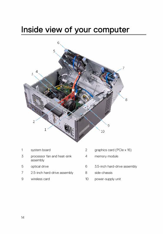
Inside view of your computer
1 system board 2 graphics card (PCIe x 16)
3 processor fan and heat-sink assembly
4 memory module
5 optical drive 6 3.5-inch hard-drive assembly
7 2.5-inch hard-drive assembly 8 side-chassis
9 wireless card 10 power-supply unit
14
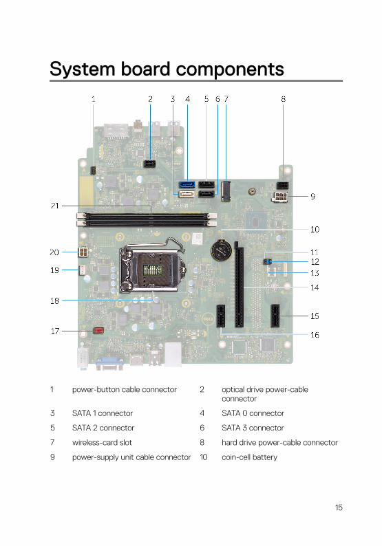
System board components
1 power-button cable connector 2 optical drive power-cable connector
3 SATA 1 connector 4 SATA 0 connector
5 SATA 2 connector 6 SATA 3 connector
7 wireless-card slot 8 hard drive power-cable connector
9 power-supply unit cable connector 10 coin-cell battery
15
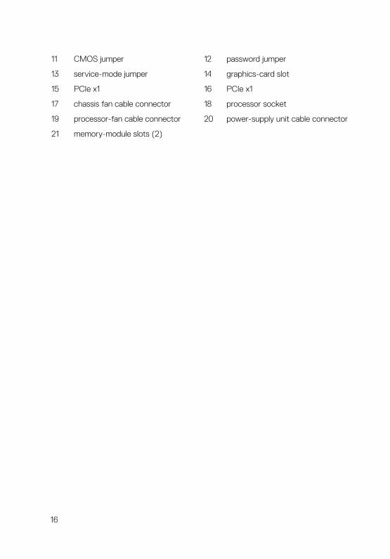
11 CMOS jumper 12 password jumper
13 service-mode jumper 14 graphics-card slot
15 PCIe x1 16 PCIe x1
17 chassis fan cable connector 18 processor socket
19 processor-fan cable connector 20 power-supply unit cable connector
21 memory-module slots (2)
16

Removing the computer cover WARNING: Before working inside your computer, read the safety information that shipped with your computer and follow the steps in Before working inside your computer. After working inside your computer, follow the instructions in After working inside your computer. For more safety best practices, see the Regulatory Compliance home page at www.dell.com/regulatory_compliance.
Procedure
1 Remove the two screws (#6-32xL6.35) that secure the cover to the chassis.
2 Release the computer cover by sliding it towards the back of the computer, lift the cover off the chassis.
17
Replacing the computer cover WARNING: Before working inside your computer, read the safety information that shipped with your computer and follow the steps in Before working inside your computer. After working inside your computer, follow the instructions in After working inside your computer. For more safety best practices, see the Regulatory Compliance home page at www.dell.com/regulatory_compliance.
Procedure
1 Align the tabs on the computer cover with the slots on the chassis and slide it towards the front of the computer.
2 Replace the two screws (#6-32xL6.35) that secure the computer cover to the chassis.
18

Removing the front bezel WARNING: Before working inside your computer, read the safety information that shipped with your computer and follow the steps in Before working inside your computer. After working inside your computer, follow the instructions in After working inside your computer. For more safety best practices, see the Regulatory Compliance home page at www.dell.com/regulatory_compliance.
Prerequisites
Remove the computer cover.
19
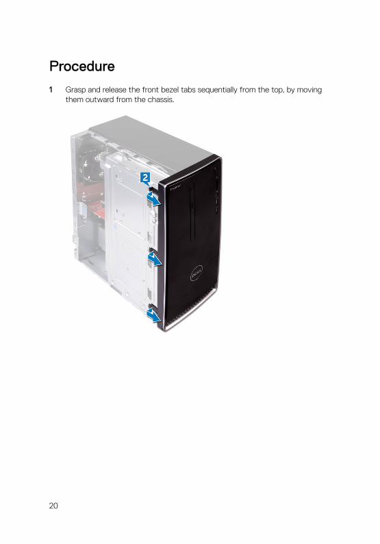
Procedure
1 Grasp and release the front bezel tabs sequentially from the top, by moving them outward from the chassis.
20
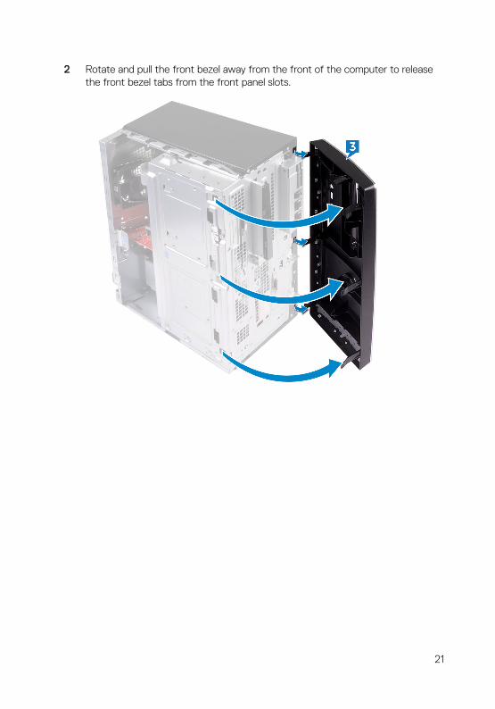
2 Rotate and pull the front bezel away from the front of the computer to release the front bezel tabs from the front panel slots.
21

Replacing the front bezelWARNING: Before working inside your computer, read the safety information that shipped with your computer and follow the steps in Before working inside your computer. After working inside your computer, follow the instructions in After working inside your computer. For more safety best practices, see the Regulatory Compliance home page at www.dell.com/regulatory_compliance.
Procedure
1 Align and insert the front bezel tabs into the front panel slots.
2 Rotate the front bezel towards the chassis until the front-bezel tabs snap into place.
Post-requisites
Replace the computer cover.
22
Removing the memory modulesWARNING: Before working inside your computer, read the safety information that shipped with your computer and follow the steps in Before working inside your computer. After working inside your computer, follow the instructions in After working inside your computer. For more safety best practices, see the Regulatory Compliance home page at www.dell.com/regulatory_compliance.
Prerequisites
Remove the computer cover.
Procedure
1 Place the computer with the side-chassis facing up.
23
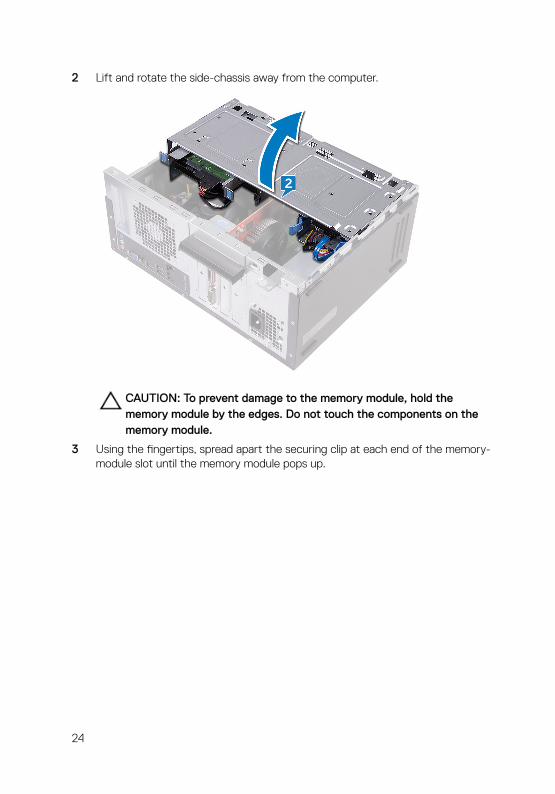
2 Lift and rotate the side-chassis away from the computer.
CAUTION: To prevent damage to the memory module, hold the memory module by the edges. Do not touch the components on the memory module.
3 Using the fingertips, spread apart the securing clip at each end of the memory-module slot until the memory module pops up.
24

4 Lift the memory module out of the memory-module slot.
NOTE: If the memory module is difficult to remove, gently ease the memory module back and forth to remove it from the slot.
25
Replacing the memory modulesWARNING: Before working inside your computer, read the safety information that shipped with your computer and follow the steps in Before working inside your computer. After working inside your computer, follow the instructions in After working inside your computer. For more safety best practices, see the Regulatory Compliance home page at www.dell.com/regulatory_compliance.
Procedure
1 Ensure that the securing clips are extended away from the memory-module slot.
2 Align the notch on the memory module with the tab on the memory-module slot.
26
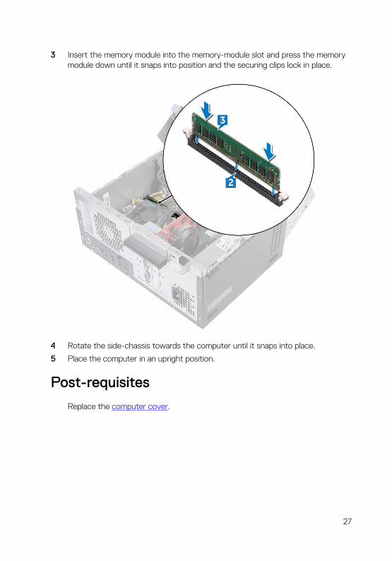
3 Insert the memory module into the memory-module slot and press the memory module down until it snaps into position and the securing clips lock in place.
4 Rotate the side-chassis towards the computer until it snaps into place.
5 Place the computer in an upright position.
Post-requisites
Replace the computer cover.
27

Removing the graphics cardWARNING: Before working inside your computer, read the safety information that shipped with your computer and follow the steps in Before working inside your computer. After working inside your computer, follow the instructions in After working inside your computer. For more safety best practices, see the Regulatory Compliance home page at www.dell.com/regulatory_compliance.
Prerequisites
Remove the computer cover.
Procedure
1 Place the computer with the side-chassis facing up.
2 Lift and rotate the side-chassis away from the computer.
28

3 Lift the tab to open the card-retention bracket.
4 Push the securing tab on the PCIe slot away from the graphics card.
29

5 Grasp the card by its top corner and lift it out of the slot.
30
Replacing the graphics cardWARNING: Before working inside your computer, read the safety information that shipped with your computer and follow the steps in Before working inside your computer. After working inside your computer, follow the instructions in After working inside your computer. For more safety best practices, see the Regulatory Compliance home page at www.dell.com/regulatory_compliance.
Procedure
1 Align the graphics card with the slot on the system board.
2 Place the card into the slot and press down firmly until the graphics card snaps into place.
3 Rotate the card retention bracket towards the chassis until it snaps into place.
4 Rotate the side-chassis towards the computer until it snaps into place.
5 Place the computer in an upright position.
Post-requisites
Replace the computer cover.
31

Removing the 3.5-inch hard driveWARNING: Before working inside your computer, read the safety information that shipped with your computer and follow the steps in Before working inside your computer. After working inside your computer, follow the instructions in After working inside your computer. For more safety best practices, see the Regulatory Compliance home page at www.dell.com/regulatory_compliance.
Prerequisites
Remove the computer cover.
Procedure
NOTE: If we have two 3.5-inch hard drives, then the drive connected to SATA 0 will be the primary drive.
1 Place the computer with the side-chassis facing up.
2 Remove the screw (#6-32xL6.35) that secures the hard-drive assembly to the side-chassis.
3 Disconnect the data cable (SATA 0) from the hard drive.
32
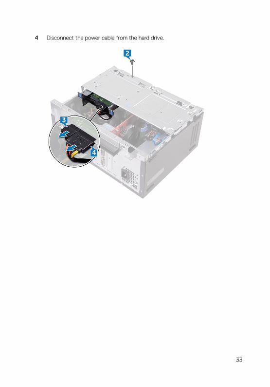
4 Disconnect the power cable from the hard drive.
33
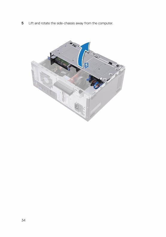
5 Lift and rotate the side-chassis away from the computer.
34

6 Using the release tabs on the hard-drive assembly, slide the hard-drive assembly out of the slot on the side-chassis.
7 Remove the four screws (#6-32xL3.6) that secure the hard-drive bracket to the hard drive.
35

8 Lift the hard drive off the hard-drive bracket.
36

Replacing the 3.5-inch hard driveWARNING: Before working inside your computer, read the safety information that shipped with your computer and follow the steps in Before working inside your computer. After working inside your computer, follow the instructions in After working inside your computer. For more safety best practices, see the Regulatory Compliance home page at www.dell.com/regulatory_compliance.
Procedure
NOTE: If we have two 3.5-inch hard drives, then the drive connected to SATA 0 will be the primary drive.
1 Place the hard drive in the hard-drive bracket.
2 Align the screw holes on the hard drive with the screw holes on the hard-drive bracket.
3 Replace the four screws (#6-32xL3.6) that secure the hard-drive bracket to the hard drive.
4 Slide the hard-drive assembly into the slot on the side-chassis until it snaps into place.
5 Connect the data cable (SATA 0) and the power cable to the hard drive.
6 Rotate the side-chassis towards the computer until it snaps into place.
7 Replace the screw (#6-32xL6.35) that secures the hard-drive assembly to the side-chassis.
8 Place the computer in an upright position.
Post-requisites
Replace the computer cover.
37

Removing the 2.5-inch hard driveWARNING: Before working inside your computer, read the safety information that shipped with your computer and follow the steps in Before working inside your computer. After working inside your computer, follow the instructions in After working inside your computer. For more safety best practices, see the Regulatory Compliance home page at www.dell.com/regulatory_compliance.
Prerequisites
Remove the computer cover.
Procedure
NOTE: If we have two 2.5-inch hard drives, then the drive connected to SATA 0 will be the primary drive.
1 Place the computer with the side-chassis facing up.
38

2 Lift and rotate the side-chassis away from the computer.
3 Disconnect the power cable from the hard drive.
4 Disconnect the data cable (SATA 1) from the hard drive.
5 Press the release tabs on the hard-drive assembly.
39

6 Slide the hard-drive assembly out of the slot on the side-chassis.
7 Pry the hard-drive bracket to release the tabs on the bracket from the slots on the hard drive.
40
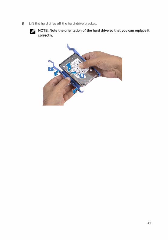
8 Lift the hard drive off the hard-drive bracket.
NOTE: Note the orientation of the hard drive so that you can replace it correctly.
41
Replacing the 2.5-inch hard driveWARNING: Before working inside your computer, read the safety information that shipped with your computer and follow the steps in Before working inside your computer. After working inside your computer, follow the instructions in After working inside your computer. For more safety best practices, see the Regulatory Compliance home page at www.dell.com/regulatory_compliance.
Procedure
NOTE: If we have two 2.5-inch hard drives, then the drive connected to SATA 0 will be the primary drive.
1 Place the hard drive into the hard-drive bracket and align the tabs on the bracket with the slots on the hard drive.
2 Snap the hard-drive bracket into the hard drive.
3 Slide the hard-drive assembly into the slot on the side-chassis.
4 Connect the data cable (SATA 1) and power cable to the hard drive.
5 Rotate the side-chassis towards the computer until it snaps into place.
6 Place the computer in an upright position.
Post-requisites
Replace the computer cover.
42
Removing the optical driveWARNING: Before working inside your computer, read the safety information that shipped with your computer and follow the steps in Before working inside your computer. After working inside your computer, follow the instructions in After working inside your computer. For more safety best practices, see the Regulatory Compliance home page at www.dell.com/regulatory_compliance.
Prerequisites
Remove the computer cover.
Procedure
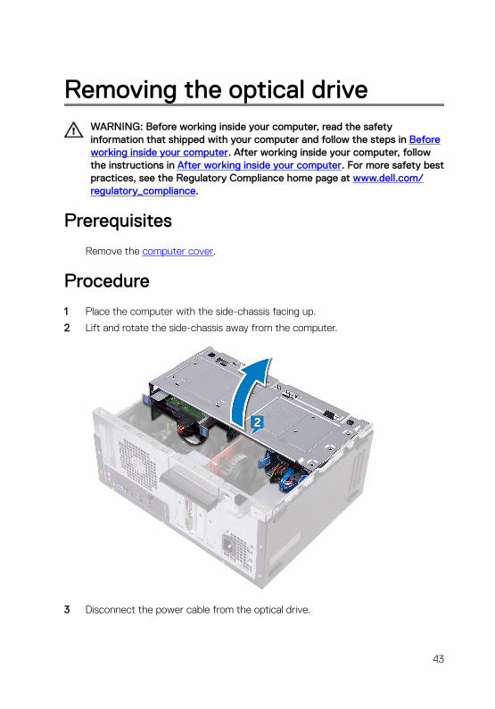
1 Place the computer with the side-chassis facing up.
2 Lift and rotate the side-chassis away from the computer.
3 Disconnect the power cable from the optical drive.
43

4 Disconnect the data cable from the optical drive.
5 Rotate the side-chassis towards the computer until it snaps into place.
6 Remove the screw (#6-32xL3.6) that secures the optical-drive assembly to the side-chassis.
44
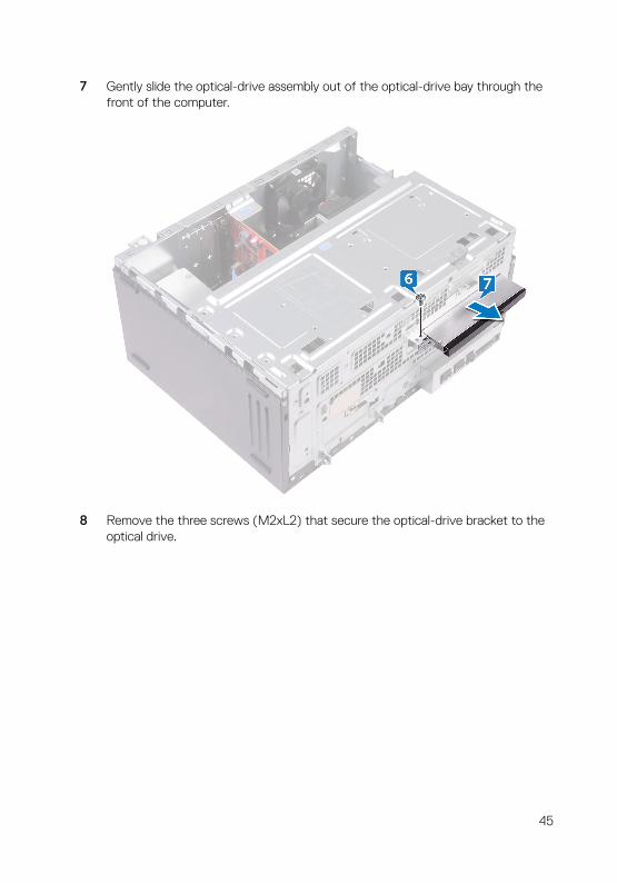
7 Gently slide the optical-drive assembly out of the optical-drive bay through the front of the computer.
8 Remove the three screws (M2xL2) that secure the optical-drive bracket to the optical drive.
45

9 Lift the optical-drive bracket off the optical drive.
10 Gently pull and disconnect the optical-drive bezel from the optical drive.
46
Replacing the optical driveWARNING: Before working inside your computer, read the safety information that shipped with your computer and follow the steps in Before working inside your computer. After working inside your computer, follow the instructions in After working inside your computer. For more safety best practices, see the Regulatory Compliance home page at www.dell.com/regulatory_compliance.
Procedure
1 Align and snap the optical-drive bezel to the optical drive.
2 Align the screw holes on the optical-drive bracket with the screw holes on the optical drive.
3 Replace the three screws (M2xL2) that secure the optical-drive bracket to the optical drive.
4 Slide the optical-drive assembly into the optical-drive bay through the front of the computer.
5 Align the screw hole on the optical-drive assembly with the screw hole on the chassis.
6 Replace the screw (#6-32xL3.6) that secures the optical-drive assembly to the chassis.
7 Lift and rotate the side-chassis away from the computer.
8 Connect the data cable and power cable to the optical drive.
9 Rotate the side-chassis towards the computer until it snaps into place.
10 Place the computer in an upright position.
Post-requisites
Replace the computer cover.
47
Removing the coin-cell batteryWARNING: Before working inside your computer, read the safety information that shipped with your computer and follow the steps in Before working inside your computer. After working inside your computer, follow the instructions in After working inside your computer. For more safety best practices, see the Regulatory Compliance home page at www.dell.com/regulatory_compliance.
CAUTION: Removing the coin-cell battery resets the BIOS setup program’s settings to default. It is recommended that you note the BIOS setup program’s settings before removing the coin-cell battery.
Prerequisites
Remove the computer cover.
Procedure
1 Place the computer with the side-chassis facing up.
48

2 Lift and rotate the side-chassis away from the computer.
49
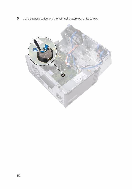
3 Using a plastic scribe, pry the coin-cell battery out of its socket.
50
Replacing the coin-cell batteryWARNING: Before working inside your computer, read the safety information that shipped with your computer and follow the steps in Before working inside your computer. After working inside your computer, follow the instructions in After working inside your computer. For more safety best practices, see the Regulatory Compliance home page at www.dell.com/regulatory_compliance.
Procedure
1 Insert a new coin-cell battery (CR2032) into the battery socket with the positive side facing up, and snap the battery into place.
2 Rotate the side-chassis towards the computer until it snaps into place.
3 Place the computer in an upright position.
Post-requisites
Replace the computer cover.
51

Removing the wireless cardWARNING: Before working inside your computer, read the safety information that shipped with your computer and follow the steps in Before working inside your computer. After working inside your computer, follow the instructions in After working inside your computer. For more safety best practices, see the Regulatory Compliance home page at www.dell.com/regulatory_compliance.
Prerequisites
Remove the computer cover.
Procedure
1 Place the computer with the side-chassis facing up.
2 Lift and rotate the side-chassis away from the computer.
52
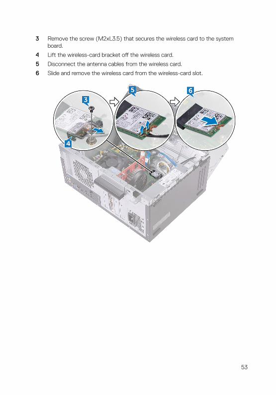
3 Remove the screw (M2xL3.5) that secures the wireless card to the system board.
4 Lift the wireless-card bracket off the wireless card.
5 Disconnect the antenna cables from the wireless card.
6 Slide and remove the wireless card from the wireless-card slot.
53

Replacing the wireless cardWARNING: Before working inside your computer, read the safety information that shipped with your computer and follow the steps in Before working inside your computer. After working inside your computer, follow the instructions in After working inside your computer. For more safety best practices, see the Regulatory Compliance home page at www.dell.com/regulatory_compliance.
Procedure
1 Align the notch on the wireless card with the tab on the wireless-card slot.
2 Slide the wireless card at an angle into the wireless-card slot.
3 Connect the antenna cables to the wireless card.
4 Slide the wireless-card bracket over the wireless card.
54

5 Replace the screw (M2xL3.5) that secures the wireless card to the system board.
6 Rotate the side-chassis towards the computer until it snaps into place.
7 Place the computer in an upright position.
Post-requisites
Replace the computer cover.
55

Removing the antenna modulesWARNING: Before working inside your computer, read the safety information that shipped with your computer and follow the steps in Before working inside your computer. After working inside your computer, follow the instructions in After working inside your computer. For more safety best practices, see the Regulatory Compliance home page at www.dell.com/regulatory_compliance.
Prerequisites
1 Remove the computer cover.
2 Remove the front bezel.
3 Follow the procedure from step 1 to step 4 in “Removing the wireless card”.
Procedure
1 Note the antenna-cable routing and remove the antenna cables from the routing guide inside the chassis.
56

2 Push down the antenna cables through the cable-routing slots on the side-chassis.
3 Rotate the side-chassis towards the computer until it snaps into place.
4 Note the antenna-cable routing and remove the antenna cables from the routing guides on the side-chassis.
57
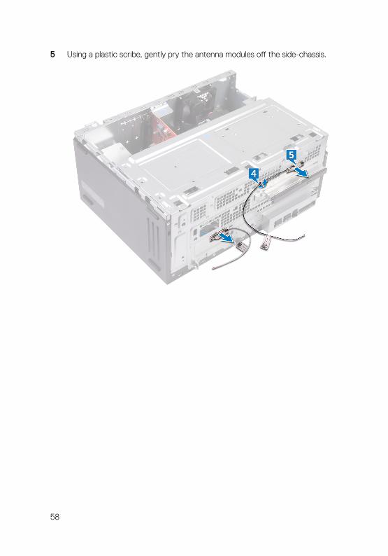
5 Using a plastic scribe, gently pry the antenna modules off the side-chassis.
58
Replacing the antenna modulesWARNING: Before working inside your computer, read the safety information that shipped with your computer and follow the steps in Before working inside your computer. After working inside your computer, follow the instructions in After working inside your computer. For more safety best practices, see the Regulatory Compliance home page at www.dell.com/regulatory_compliance.
Procedure
1 Adhere the antenna modules to the side-chassis.
2 Route the antenna cables through the routing guides on the side-chassis.
3 Lift and rotate the side-chassis away from the computer.
4 Slide the antenna cables through the cable-routing slots on the side-chassis.
5 Route the antenna cables through the routing guides inside the chassis.
Post-requisites
1 Follow the procedure from step 3 to step 6 in “Replacing the wireless card”.
2 Replace the front bezel.
3 Replace the computer cover.
59
Removing the power-button module
WARNING: Before working inside your computer, read the safety information that shipped with your computer and follow the steps in Before working inside your computer. After working inside your computer, follow the instructions in After working inside your computer. For more safety best practices, see the Regulatory Compliance home page at www.dell.com/regulatory_compliance.
Prerequisites
Remove the computer cover.
Procedure
1 Place the computer with the side-chassis facing up.
60

2 Lift and rotate the side-chassis away from the computer.
3 Disconnect the power-button cable from the system board.
4 Press the tabs on the power-button module to release the module from the front panel.
61

5 Remove the power-button module along with its cable through the slot on the front panel.
62
Replacing the power-button module
WARNING: Before working inside your computer, read the safety information that shipped with your computer and follow the steps in Before working inside your computer. After working inside your computer, follow the instructions in After working inside your computer. For more safety best practices, see the Regulatory Compliance home page at www.dell.com/regulatory_compliance.
Procedure
1 Route the power-button board cable through the slot on the front panel.
2 Align and snap the power-button module into the slot on the front panel.
3 Connect the power-button board cable to the system board.
4 Rotate the side-chassis towards the computer until it snaps into place.
Post-requisites
Replace the computer cover.
63

Removing the chassis fanWARNING: Before working inside your computer, read the safety information that shipped with your computer and follow the steps in Before working inside your computer. After working inside your computer, follow the instructions in After working inside your computer. For more safety best practices, see the Regulatory Compliance home page at www.dell.com/regulatory_compliance.
Prerequisites
Remove the computer cover.
Procedure
1 Place the computer with the side-chassis facing up.
2 Lift and rotate the side-chassis away from the computer.
3 Disconnect the chassis-fan cable from the system board.
64

4 Remove the four screws (#6-32xL6.35) that secure the chassis fan to the chassis.
5 Remove the chassis fan from the chassis.
65

Replacing the chassis fanWARNING: Before working inside your computer, read the safety information that shipped with your computer and follow the steps in Before working inside your computer. After working inside your computer, follow the instructions in After working inside your computer. For more safety best practices, see the Regulatory Compliance home page at www.dell.com/regulatory_compliance.
Procedure
1 Align the screw holes on the chassis fan with the screw holes on the chassis.
2 Replace the four screws (#6-32xL6.35) that secure the chassis fan to the chassis.
3 Connect the chassis-fan cable to the system board.
4 Rotate the side-chassis towards the computer until it snaps into place.
Post-requisites
Replace the computer cover.
66
Removing the power-supply unitWARNING: Before working inside your computer, read the safety information that shipped with your computer and follow the steps in Before working inside your computer. After working inside your computer, follow the instructions in After working inside your computer. For more safety best practices, see the Regulatory Compliance home page at www.dell.com/regulatory_compliance.
Prerequisites
Remove the computer cover.
Procedure
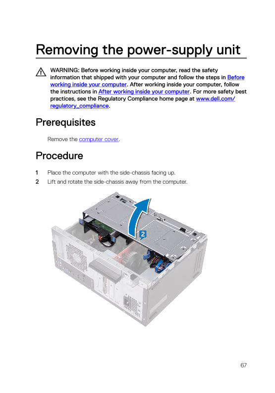
1 Place the computer with the side-chassis facing up.
2 Lift and rotate the side-chassis away from the computer.
67

3 Press the securing clip and disconnect the power-supply unit cable (ATX2) from the system board.
4 Press the securing clip and disconnect the power-supply unit cable (ATX1) from the system board.
5 Note the power-supply unit cable routing and remove the power-supply unit cable from the routing guides on the chassis.
6 Remove the three screws (#6-32xL6.35) that secure the power-supply unit to the chassis.
7 Press the clamp and slide the power-supply unit towards the front of the chassis to release it from the chassis.
68

8 Lift the power-supply unit, along with the cables, off the chassis.
69
Replacing the power-supply unitWARNING: Before working inside your computer, read the safety information that shipped with your computer and follow the steps in Before working inside your computer. After working inside your computer, follow the instructions in After working inside your computer. For more safety best practices, see the Regulatory Compliance home page at www.dell.com/regulatory_compliance.
Procedure
1 Place the power-supply unit on the chassis.
2 Slide the power-supply unit towards the back of the chassis until it snaps into place.
3 Align the screw holes on the power-supply unit with the screw holes on the chassis.
4 Replace the three screws (#6-32xL6.35) that secure the power-supply unit to the chassis.
5 Route the power-supply unit cable through the routing guides inside the chassis.
6 Connect the power-supply unit cables (ATX 1 and ATX 2) to the system board.
7 Rotate the side-chassis towards the computer until it snaps into place.
Post-requisites
Replace the computer cover.
70
Removing the processor fanWARNING: Before working inside your computer, read the safety information that shipped with your computer and follow the steps in Before working inside your computer. After working inside your computer, follow the instructions in After working inside your computer. For more safety best practices, see the Regulatory Compliance home page at www.dell.com/regulatory_compliance.
Prerequisites
Remove the computer cover.
Procedure
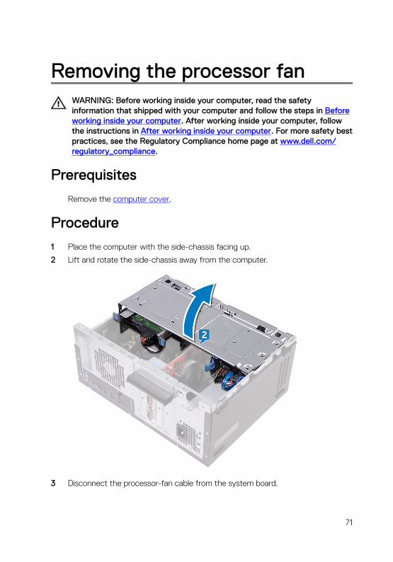
1 Place the computer with the side-chassis facing up.
2 Lift and rotate the side-chassis away from the computer.
3 Disconnect the processor-fan cable from the system board.
71

4 Remove the four screws (M6xL10) that secure the processor fan to the heat sink.
5 Lift the processor fan off the heat sink.
72
Replacing the processor fanWARNING: Before working inside your computer, read the safety information that shipped with your computer and follow the steps in Before working inside your computer. After working inside your computer, follow the instructions in After working inside your computer. For more safety best practices, see the Regulatory Compliance home page at www.dell.com/regulatory_compliance.
Procedure
1 Align the screw holes on the processor fan with the screw holes on the heat sink.
2 Replace the four screws (M6xL10) that secure the processor fan to the heat sink.
3 Connect the processor-fan cable to the system board.
4 Rotate the side-chassis towards the computer until it snaps into place.
Post-requisites
Replace the computer cover.
73

Removing the processor heat-sink
WARNING: Before working inside your computer, read the safety information that shipped with your computer and follow the steps in Before working inside your computer. After working inside your computer, follow the instructions in After working inside your computer. For more safety best practices, see the Regulatory Compliance home page at www.dell.com/regulatory_compliance.
CAUTION: For maximum cooling of the processor, do not touch the heat transfer areas on the heat sink. The oils in your skin can reduce the heat transfer capability of the thermal grease.
Prerequisites
1 Remove the computer cover.
2 Remove the front bezel.
3 Remove the processor fan.
Procedure
1 Loosen the captive screws that secure the heat-sink assembly to the system board.
74

2 Lift the heat-sink assembly off the system board.
75

Replacing the processor heat-sink
WARNING: Before working inside your computer, read the safety information that shipped with your computer and follow the steps in Before working inside your computer. After working inside your computer, follow the instructions in After working inside your computer. For more safety best practices, see the Regulatory Compliance home page at www.dell.com/regulatory_compliance.
CAUTION: For maximum cooling of the processor, do not touch the heat transfer areas on the heat sink. The oils in your skin can reduce the heat transfer capability of the thermal grease.
Procedure
1 Place the heat sink over the processor.
2 Align the captive screws on the heat-sink assembly with the screw holes on the system board.
3 Tighten the captive screws that secure the heat sink to the system board.
Post-requisites
1 Replace the processor fan.
2 Replace the front bezel.
3 Replace the computer cover.
76

Removing the system boardWARNING: Before working inside your computer, read the safety information that shipped with your computer and follow the steps in Before working inside your computer. After working inside your computer, follow the instructions in After working inside your computer. For more safety best practices, see the Regulatory Compliance home page at www.dell.com/regulatory_compliance.
NOTE: Your computer’s Service Tag is stored in the system board. You must enter the Service Tag in the BIOS setup program after you replace the system board.
NOTE: Replacing the system board removes any changes you have made to the BIOS using the BIOS setup program. You must make the appropriate changes again after you replace the system board.
NOTE: Before disconnecting the cables from the system board, note the location of the connectors so that you can reconnect the cables correctly after you replace the system board.
Prerequisites
1 Remove the computer cover.
2 Remove the front bezel.
3 Remove the memory modules.
4 Remove the wireless card.
5 Remove the processor fan.
6 Remove the heat sink.
Procedure
NOTE: Note the routing of all cables as you remove them so that you can reroute them correctly after you replace the system board. For information on system board connectors, see “System board components’.
1 Disconnect the chassis-fan cable from the system board.
2 Disconnect the power-supply unit cable from the system board.
3 Disconnect the power-button cable from the system board.
77
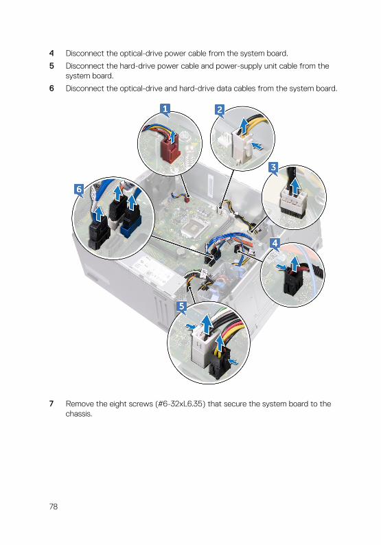
4 Disconnect the optical-drive power cable from the system board.
5 Disconnect the hard-drive power cable and power-supply unit cable from the system board.
6 Disconnect the optical-drive and hard-drive data cables from the system board.
7 Remove the eight screws (#6-32xL6.35) that secure the system board to the chassis.
78
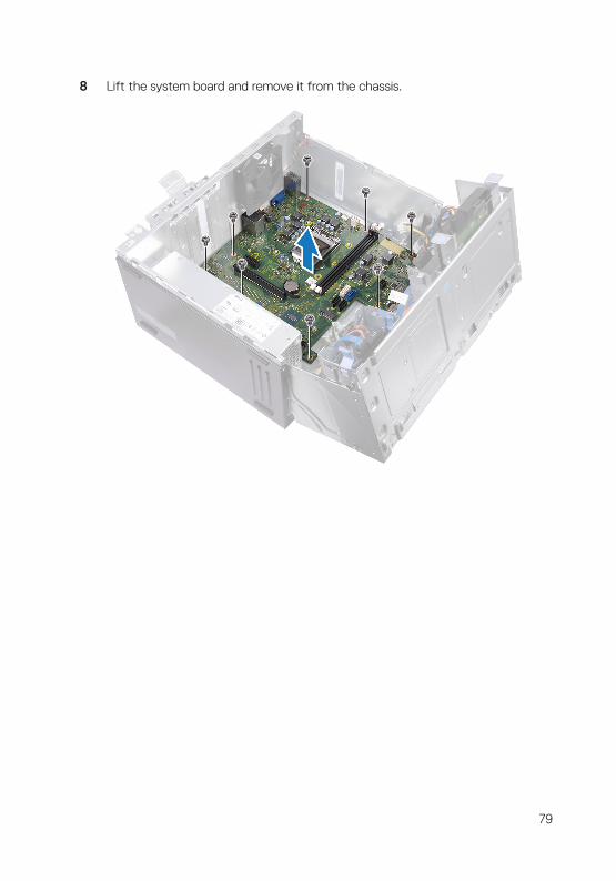
8 Lift the system board and remove it from the chassis.
79

Replacing the system boardWARNING: Before working inside your computer, read the safety information that shipped with your computer and follow the steps in Before working inside your computer. After working inside your computer, follow the instructions in After working inside your computer. For more safety best practices, see the Regulatory Compliance home page at www.dell.com/regulatory_compliance.
NOTE: Your computer’s Service Tag is stored in the system board. You must enter the Service Tag in the BIOS setup program after you replace the system board.
NOTE: Replacing the system board removes any changes you have made to the BIOS using the BIOS setup program. You must make the appropriate changes again after you replace the system board.
Procedure
1 Align the system board with the slots on the chassis and place the system board in position.
2 Replace the eight screws (#6-32xL6.35') that secure the system board to the chassis.
3 Route the chassis-fan cable, optical-drive data cable, hard-drive data cable, hard-drive and optical-drive power cables, power-supply unit cable, and power-button cable through their routing guides on the chassis and connect the cables to their respective connectors on the system board.
Post-requisites
1 Replace the processor heat sink.
2 Replace the processor fan.
3 Replace the wireless card.
4 Replace the memory modules.
5 Replace the front bezel.
6 Replace the computer cover.
80

BIOS setup program
BIOS overview
The BIOS manages data flow between the computer's operating system and attached devices such as hard disk, video adapter, keyboard, mouse, and printer.
Entering BIOS setup program
1 Turn on (or restart) your computer.
2 During POST, when the DELL logo is displayed, watch for the F2 prompt to appear, and then press F2 immediately.
NOTE: The F2 prompt indicates that the keyboard is initialized. This prompt can appear very quickly, so you must watch for it, and then press F2. If you press F2 before the F2 prompt, this keystroke is lost. If you wait too long and the operating system logo appears, continue to wait until you see the desktop. Then, turn off your computer and try again.
System setup options
NOTE: Depending on this computer and its installed devices, the items listed in this section may or may not appear.
Table 2. System setup options—System information menu
General-System Information
System Information
BIOS Version Displays the BIOS version number.
Service Tag Displays the Service Tag of the computer.
Asset Tag Displays the Asset Tag of the computer.
Ownership Tag Displays the Ownership Tag of the computer.
Manufacture Date Displays the manufacture date of the computer.
Ownership Date Displays the ownership date of the computer.
81

General-System Information
Express Service Code Displays the express service code of the computer.
Memory Information
Memory Installed Displays the total computer memory installed.
Memory Available Displays the total computer memory available.
Memory Speed Displays the memory speed.
Memory Channel Mode Displays single or dual channel mode.
Memory Technology Displays the technology used for the memory.
DIMM 1Size Displays the DIMM A memory size.
DIMM 2 Size Displays the DIMM B memory size.
PCI Information
Slot 1 Displays the PCI slot 1 information of the computer.
Slot 2 Displays the PCI slot 2 information of the computer.
Slot 3 Displays the PCI slot 3 information of the computer.
Processor Information
Processor Type Displays the processor type.
Core Count Displays the number of cores on the processor.
Processor ID Displays the processor identification code.
Current Clock Speed Displays the current processor clock speed.
Minimum Clock Speed Displays the minimum processor clock speed.
Maximum Clock Speed Displays the maximum processor clock speed.
Processor L2 Cache Displays the processor L2 Cache size.
Processor L3 Cache Displays the processor L3 Cache size.
HT Capable Displays whether the processor is HyperThreading (HT) capable.
64-Bit Technology Displays whether 64-bit technology is used.
Device Information
82
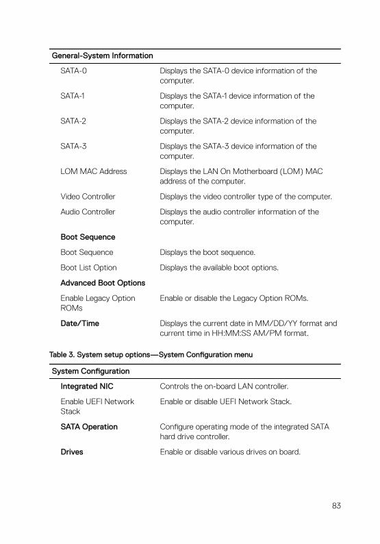
General-System Information
SATA-0 Displays the SATA-0 device information of the computer.
SATA-1 Displays the SATA-1 device information of the computer.
SATA-2 Displays the SATA-2 device information of the computer.
SATA-3 Displays the SATA-3 device information of the computer.
LOM MAC Address Displays the LAN On Motherboard (LOM) MAC address of the computer.
Video Controller Displays the video controller type of the computer.
Audio Controller Displays the audio controller information of the computer.
Boot Sequence
Boot Sequence Displays the boot sequence.
Boot List Option Displays the available boot options.
Advanced Boot Options
Enable Legacy Option ROMs
Enable or disable the Legacy Option ROMs.
Date/Time Displays the current date in MM/DD/YY format and current time in HH:MM:SS AM/PM format.
Table 3. System setup options—System Configuration menu
System Configuration
Integrated NIC Controls the on-board LAN controller.
Enable UEFI Network Stack
Enable or disable UEFI Network Stack.
SATA Operation Configure operating mode of the integrated SATA hard drive controller.
Drives Enable or disable various drives on board.
83

System Configuration
SMART Reporting Enable or disable Self-Monitoring, Analysis, and Reporting Technology (SMART) during system startup.
USB Configuration
Enable Boot Support Enable or disable booting from USB mass storage devices such as external hard drive, optical drive, and USB drive.
Enable External USB Port Enable or disable booting from USB mass storage devices connected to external USB port.
Front USB Configuration Enable or disable front USB port(s)
Rear USB Configuration Enable or disable rear USB port(s)
Audio Enable or disable the integrated audio controller.
Miscellaneous Devices Enable or disable various onboard devices.
Enable PCI Slot Enable or disable the PCI slot.
Enable Secure Digital (SD) Card
Enable or disable the SD card.
Secure Digital (SD) Card Boot
Enable or disable the SD card boot.
Table 4. System setup options—Video menu
Video
Multi-Display Enable or disable the Multi-Display.
Primary Display Select the primary video controller.
Table 5. System setup options—Security menu
Security
Admin Password Set, change, or delete the administrator password.
System Password Set, change, or delete the system password.
Internal HDD-0 Password Set, change, or delete the internal hard-disk drive password.
84
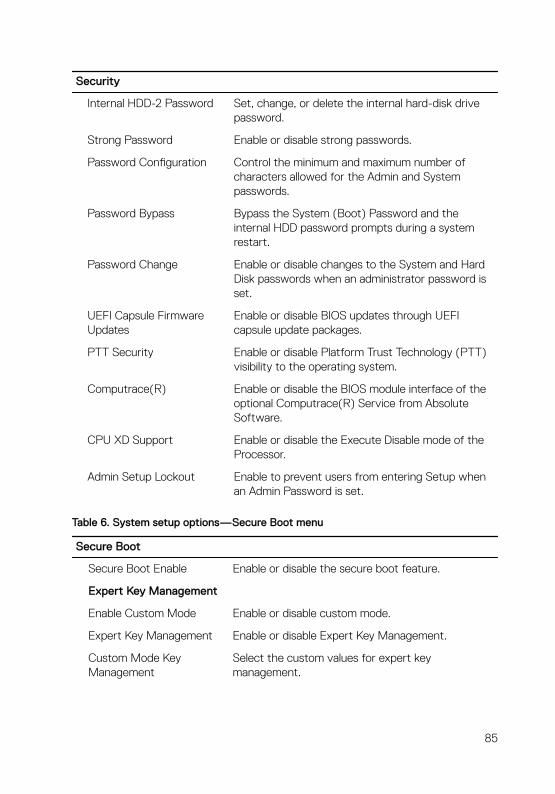
Security
Internal HDD-2 Password Set, change, or delete the internal hard-disk drive password.
Strong Password Enable or disable strong passwords.
Password Configuration Control the minimum and maximum number of characters allowed for the Admin and System passwords.
Password Bypass Bypass the System (Boot) Password and the internal HDD password prompts during a system restart.
Password Change Enable or disable changes to the System and Hard Disk passwords when an administrator password is set.
UEFI Capsule Firmware Updates
Enable or disable BIOS updates through UEFI capsule update packages.
PTT Security Enable or disable Platform Trust Technology (PTT) visibility to the operating system.
Computrace(R) Enable or disable the BIOS module interface of the optional Computrace(R) Service from Absolute Software.
CPU XD Support Enable or disable the Execute Disable mode of the Processor.
Admin Setup Lockout Enable to prevent users from entering Setup when an Admin Password is set.
Table 6. System setup options—Secure Boot menu
Secure Boot
Secure Boot Enable Enable or disable the secure boot feature.
Expert Key Management
Enable Custom Mode Enable or disable custom mode.
Expert Key Management Enable or disable Expert Key Management.
Custom Mode Key Management
Select the custom values for expert key management.
85
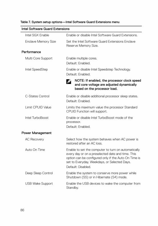
Table 7. System setup options—Intel Software Guard Extensions menu
Intel Software Guard Extensions
Intel SGX Enable Enable or disable Intel Software Guard Extensions.
Enclave Memory Size Set the Intel Software Guard Extensions Enclave Reserve Memory Size.
Performance
Multi Core Support Enable multiple cores.
Default: Enabled.
Intel SpeedStep Enable or disable Intel Speedstep Technology.
Default: Enabled.
NOTE: If enabled, the processor clock speed and core voltage are adjusted dynamically based on the processor load.
C-States Control Enable or disable additional processor sleep states.
Default: Enabled.
Limit CPUID Value Limits the maximum value the processor Standard CPUID Function will support.
Intel TurboBoost Enable or disable Intel TurboBoost mode of the processor.
Default: Enabled.
Power Management
AC Recovery Select how the system behaves when AC power is restored after an AC loss.
Auto On Time Enable to set the computer to turn on automatically every day or on a preselected date and time. This option can be configured only if the Auto On Time is set to Everyday, Weekdays, or Selected Days.
Default: Disabled.
Deep Sleep Control Enable the system to conserve more power while Shutdown (SS) or in Hibernate (S4) mode.
USB Wake Support Enable the USB devices to wake the computer from Standby.
86
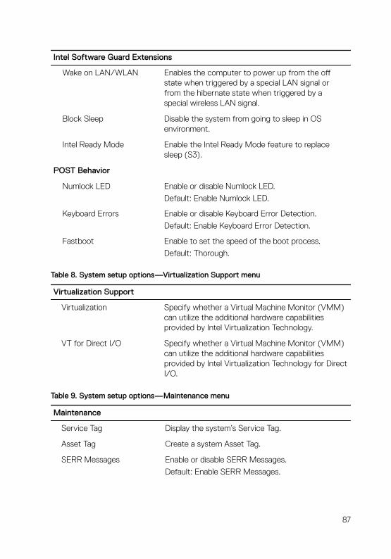
Intel Software Guard Extensions
Wake on LAN/WLAN Enables the computer to power up from the off state when triggered by a special LAN signal or from the hibernate state when triggered by a special wireless LAN signal.
Block Sleep Disable the system from going to sleep in OS environment.
Intel Ready Mode Enable the Intel Ready Mode feature to replace sleep (S3).
POST Behavior
Numlock LED Enable or disable Numlock LED.
Default: Enable Numlock LED.
Keyboard Errors Enable or disable Keyboard Error Detection.
Default: Enable Keyboard Error Detection.
Fastboot Enable to set the speed of the boot process.
Default: Thorough.
Table 8. System setup options—Virtualization Support menu
Virtualization Support
Virtualization Specify whether a Virtual Machine Monitor (VMM) can utilize the additional hardware capabilities provided by Intel Virtualization Technology.
VT for Direct I/O Specify whether a Virtual Machine Monitor (VMM) can utilize the additional hardware capabilities provided by Intel Virtualization Technology for Direct I/O.
Table 9. System setup options—Maintenance menu
Maintenance
Service Tag Display the system’s Service Tag.
Asset Tag Create a system Asset Tag.
SERR Messages Enable or disable SERR Messages.
Default: Enable SERR Messages.
87
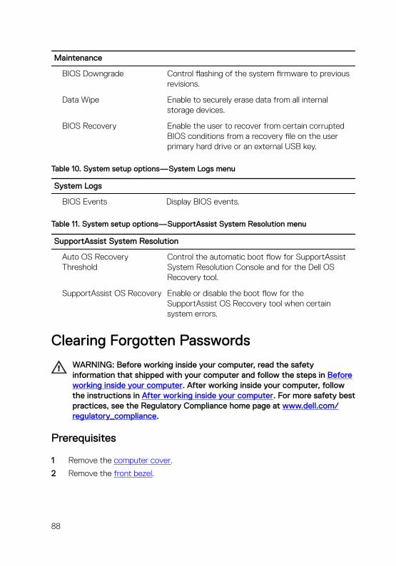
Maintenance
BIOS Downgrade Control flashing of the system firmware to previous revisions.
Data Wipe Enable to securely erase data from all internal storage devices.
BIOS Recovery Enable the user to recover from certain corrupted BIOS conditions from a recovery file on the user primary hard drive or an external USB key.
Table 10. System setup options—System Logs menu
System Logs
BIOS Events Display BIOS events.
Table 11. System setup options—SupportAssist System Resolution menu
SupportAssist System Resolution
Auto OS Recovery Threshold
Control the automatic boot flow for SupportAssist System Resolution Console and for the Dell OS Recovery tool.
SupportAssist OS Recovery Enable or disable the boot flow for the SupportAssist OS Recovery tool when certain system errors.
Clearing Forgotten Passwords
WARNING: Before working inside your computer, read the safety information that shipped with your computer and follow the steps in Before working inside your computer. After working inside your computer, follow the instructions in After working inside your computer. For more safety best practices, see the Regulatory Compliance home page at www.dell.com/regulatory_compliance.
Prerequisites
1 Remove the computer cover.
2 Remove the front bezel.
88

Procedure
1 Place the computer with the side-chassis facing up.
2 Lift and rotate the side-chassis away from the computer.
3 Locate the password jumper on the system board.
NOTE: For more information on the location of the jumper, see System-board components.
4 Remove the jumper plug from the password jumper-pins.
89

5 Wait for 5 seconds and then replace the jumper plug in its original location.
6 Rotate the side-chassis towards the computer until it snaps into place.
Post-requisites
1 Replace the front bezel.
2 Replace the computer cover.
90

Clearing CMOS Settings
WARNING: Before working inside your computer, read the safety information that shipped with your computer and follow the steps in Before working inside your computer. After working inside your computer, follow the instructions in After working inside your computer. For more safety best practices, see the Regulatory Compliance home page at www.dell.com/regulatory_compliance.
Prerequisites
1 Remove the computer cover.
2 Remove the front bezel.
Procedure
1 Place the computer with the side-chassis facing up.
91

2 Lift and rotate the side-chassis away from the computer.
3 Locate the CMOS jumper on the system board.
NOTE: For more information on the location of the jumper, see System-board components.
4 Remove the jumper plug from the password jumper-pins (PSWD) and connect it to the CMOS jumper-pins.
92
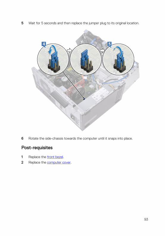
5 Wait for 5 seconds and then replace the jumper plug to its original location.
6 Rotate the side-chassis towards the computer until it snaps into place.
Post-requisites
1 Replace the front bezel.
2 Replace the computer cover.
93

Flashing the BIOSYou may need to flash (update) the BIOS when an update is available or when you replace the system board.
Follow these steps to flash the BIOS:
1 Turn on your computer.
2 Go to www.dell.com/support.
3 Click Product support, enter the Service Tag of your computer, and then click Submit.
NOTE: If you do not have the Service Tag, use the auto-detect feature or manually browse for your computer model.
4 Click Drivers & downloads → Find it myself.
5 Select the operating system installed on your computer.
6 Scroll down the page and expand BIOS.
7 Click Download to download the latest version of the BIOS for your computer.
8 After the download is complete, navigate to the folder where you saved the BIOS update file.
9 Double-click the BIOS update file icon and follow the instructions on the screen.
94
Getting help and contacting Dell
Self-help resources
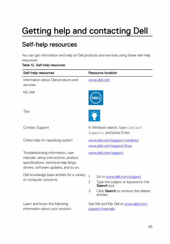
You can get information and help on Dell products and services using these self-help resources:Table 12. Self-help resources
Self-help resources Resource location
Information about Dell products and services
www.dell.com
My Dell
Tips
Contact Support In Windows search, type Contact Support, and press Enter.
Online help for operating system www.dell.com/support/windows
www.dell.com/support/linux
Troubleshooting information, user manuals, setup instructions, product specifications, technical help blogs, drivers, software updates, and so on.
www.dell.com/support
Dell knowledge base articles for a variety of computer concerns.
1 Go to www.dell.com/support.
2 Type the subject or keyword in the Search box.
3 Click Search to retrieve the related articles.
Learn and know the following information about your product:
See Me and My Dell at www.dell.com/support/manuals.
95
Self-help resources Resource location
• Product specifications
• Operating system
• Setting up and using your product
• Data backup
• Troubleshooting and diagnostics
• Factory and system restore
• BIOS information
To locate the Me and My Dell relevant to your product, identify your product through one of the following:
• Select Detect Product.
• Locate your product through the drop-down menu under View Products.
• Enter the Service Tag number or Product ID in the search bar.
Contacting Dell
To contact Dell for sales, technical support, or customer service issues, see www.dell.com/contactdell.
NOTE: Availability varies by country and product, and some services may not be available in your country.
NOTE: If you do not have an active internet connection, you can find contact information on your purchase invoice, packing slip, bill, or Dell product catalog.
96