inspection form page 1 of 3 automatic … · cable temperature: ooc temperature correction factor...
TRANSCRIPT

Form ATS-600V Rev 00, Created by SNC-Lavalin Inc. L:\40ENG\Clients\City of Winnipeg\Forms\Electrical\F-ATS-600V.doc
INSPECTION FORM AUTOMATIC TRANSFER SWITCH, 600V
Page 1 of 3
ID:
Pro
ject
Facility: Project Name:
Area : Bid Opportunity:
Tra
nsfe
r S
wit
ch
Data
Manufacturer: Type: Serial #:
Rated Voltage: V Current Rating: A Control Voltage: V
Control Power Transformer:
Size: VAPrimary Voltage (Tap Setting):
V Primary Fuse: A
Adjustable Taps:
Yes No Secondary Voltage: V Secondary Fuse: A
Vis
ual In
sp
ecti
on
/ C
lean
ing
Identification Tag Installed: Yes No Visual Signs of Overheating: Yes No
Cleanliness (As Found): Good Acceptable Poor Support Insulators: Good Acceptable Poor
Connections: Good Acceptable PoorElectro/Mechanical Interlock:
N/A Good Acceptable Poor
Ground Connection: Good Acceptable PoorContactor Switch Condition:
Good Acceptable Poor
Door Mechanical: Good Acceptable Poor Contact Alignment: Good Acceptable Poor
Cables Supported Appropriately: Yes No Exercise Contactors/Switch: Yes
Unit Cleaned: Yes Photograph Taken: Yes
Comments:
Sett
ing
s
Source 1 (Normal) Dropout Voltage: V Transfer to Source 2 Delay: sec.
Source 1 (Normal) Pickup Voltage: V Retransfer to Source 1 Delay: sec.
Source 2 (Emergency) Dropout Voltage: V Engine Cool-Down Delay: sec.
Source 2 (Emergency) Pickup Voltage: V
Co
nta
ct/
Po
le
Measu
rem
en
ts
Contactor/Switch Position
Resistance (µ�) Test Summary
Test Passed Test Inconclusive
Further Investigation Required. Test Failed
A B C
Source 1 (Normal) to Output
Source 2 (Emergency) to Output
Comments:

INSPECTION FORM AUTOMATIC TRANSFER SWITCH, 600V
Page 2 of 3
ID:
Form ATS-600V Rev 00, Created by SNC-Lavalin Inc. L:\40ENG\Clients\City of Winnipeg\Forms\Electrical\F-ATS-600V.doc
Insu
lati
on
Resis
tan
ce T
est
Test Preparation:
Source 1 (Normal) Cable: Disconnected Connected with Source Isolated
Source 2 (Emerg.) Cable: Disconnected Connected with
Source Isolated
Output Cable: Disconnected Connected with Source Isolated
Note: Approval of City’s Representative is required, prior to leaving cables connected during the test.
Voltage: 1000 VDC. Ground all phases not under test!
Test Position
Insulation Resistance (M�)
Switch PositionSource 1 (Normal)
Switch PositionSource 2 (Emergency)
A B C A B C
Source 1 Line to GND
Source 2 Line to GND
Output Line to GND
Source 1 Line to Output N/A N/A N/A
Source 2 Line to Output N/A N/A N/A
Comments:
Test Summary Test Passed
Test Inconclusive - Further Investigation Required
Test Failed
Fu
ncti
on
al T
esti
ng
Step Description Result
1 ATS in Source 1 (Normal) Position with Source 1 Energized. ATS indicates Source 1 available and Source 1 position status is provided.
Pass Fail
2 Power down (or isolate) Source 1. ATS indicates Source 1 is not available. Pass Fail
3 Source 2/Generator start signal provided. Pass Fail
4 Source 2/Generator starts. ATS indicates Source 2 available and transfers to Source 2 after appropriate delay. Source 2 position status is displayed..
Pass Fail
5 Power up (or reconnect) Source 1. ATS indicates Source 1 is available and delay timer starts before transfer back to Source 1. ATS continues to indicate Source 2 position status.
Pass Fail
6 Timer expires and ATS transfers to Source 1. ATS indicates Source 1 position status. Pass Fail
7 Generator Stops after cool-down timer expires. Pass Fail
8 Ensure loads are isolated such that a phase loss will not damage equipment. Simulate a Source 1 phase loss condition and verify the ATS starts Source 2/Generator and transfers to Source 2.
Pass Fail
9 Reinstate the lost phase on Source 1 and verify that ATS transfers back to Source 1 after the appropriate delay.
Pass Fail
10 Manually start Source 2/Generator and perform a manual transfer to Source 2. Pass Fail
11 Perform a manual transfer back to Source 1. Pass Fail
Test Summary Test Passed
Test Inconclusive - Further Investigation Required
Test Failed

INSPECTION FORM AUTOMATIC TRANSFER SWITCH, 600V
Page 3 of 3
ID:
Form ATS-600V Rev 00, Created by SNC-Lavalin Inc. L:\40ENG\Clients\City of Winnipeg\Forms\Electrical\F-ATS-600V.doc
Fin
al A
naly
sis
Returned to Service: Yes NoComments:
Monitoring / Further Inspection Required:
Yes No
Repair / Replacement Required: Yes No
Company Name Signature Date (yyyy/mm/dd)
Performed By
Checked By
Note: The person performing the check is responsible for ensuring that the data is transcribed from the handwritten form correctly, and that the analysis results are correct.

Form F-BKR-MC-LV Rev 02, Created by SNC-Lavalin Inc. L:\40ENG\Clients\City of Winnipeg\Electrical\Forms\F-BKR-MC-LV.doc
Page 1 of 2 INSPECTION FORM MOLDED CASE CIRCUIT BREAKER, < 1000V
ID:
Facility: Project Name: P
roje
ct
Area : Bid Opportunity:
Location: Panelboard/MCC: Cell #:
Manufacturer: Type: Serial #:
Rated Voltage: V Frame Size: A Trip Unit:
Bre
ak
er
Da
ta
Interrupting Rating: kA Comments:
Breaker Identification Tag Installed: Yes No Visual Signs of Overheating: Yes No
Cleanliness (As Found): Good Acceptable Poor Cables Supported Appropriately: Yes No
Connections: Good Acceptable PoorElectro/Mechanical Interlock:
N/A Good Acceptable Poor
Ground Connection: Good Acceptable Poor Exercise Circuit Breaker: Yes
Door Mechanical: Good Acceptable Poor Other: Vis
ua
l In
sp
ec
tio
n /
Cle
an
ing
Comments:
Trip Unit Rating: A Trip Unit Type: None Thermal Magnetic Electronic LI LSI LSIG
Breaker Setting (As Left) Range Setpoint Delay I2T
Long Time Fixed Adj. - X A = A sec On Off
Short Time Fixed Adj. - X A = A sec On Off
Instantaneous Fixed Adj. - X A = A N/A Bre
ak
er
Se
ttin
gs
Ground Fault Fixed Adj. - A sec On Off
Perform insulation resistance measurements for breakers >= 250A, or as specified.
Source: Disconnected Connected (Source Isolated) Temperature:
oC
Load: Disconnected Connected (Load Isolated)
Approval is required, prior to leaving cables connected during the test.
Insulation Resistance (M�)
Phase To GND (Breaker Closed) Phase To Phase (Breaker Closed) Line to Load (Breaker Open)
Test Voltage (VDC)
A B C A – B B – C A - C A B C
Test Summary Test Passed Test Inconclusive. Further Investigation Required. Test Failed
Ins
ula
tio
n R
es
ista
nc
e T
es
t
Comments:
Perform contact measurements for breakers >= 250A, or as specified.
A B C Resistance (µ�)
Co
nta
ct
Re
sis
tan
ce
Comments:
Test Summary Test Passed Test Inconclusive
Further Investigation Required. Test Failed

Page 2 of 2 INSPECTION FORM MOLDED CASE CIRCUIT BREAKER, < 1000V
ID:
Form F-BKR-MC-LV Rev 02, Created by SNC-Lavalin Inc. L:\40ENG\Clients\City of Winnipeg\Electrical\Forms\F-BKR-MC-LV.doc
Returned to Service: Yes No
Monitoring / Further Inspection Required: Yes No
Fin
al
An
aly
sis
Repair / Replacement Required: Yes No
Comments:
Company Name Signature Date (yyyy/mm/dd)
Performed By
Checked By
Note: The person(s) performing the check is responsible for ensuring that the data is transcribed from the handwritten form correctly, and that the analysis results are correct.

Form F-CAP-600V Rev 00, Created by SNC-Lavalin Inc. M:\113099\4ENG\47ELE\RA - Misc Reports & Forms\Forms\F-CAP-600V.doc
Page 1 of 1
INSPECTION FORM CAPACITOR BANK, 600V
ID:
Facility: Project Name: P
roje
ct
Area : Bid Opportunity:
Location: Switchgear/MCC: Cell #:
Manufacturer: Model: Serial #:
Size: VAR Rated Voltage: V Capacitance: µF
Cap
acit
or
Ban
k
Data
Configuration: Delta Wye-Ungrounded Wye-Grounded
Capacitor Identification Tag Installed: Yes No Cables Supported Appropriately: Yes No
Cleanliness (As Found): Good Acceptable Poor Anchorage, alignment: Good Acceptable Poor
Connections: Good Acceptable Poor Required Clearances: Good Acceptable PoorVis
ual
Insp
ecti
on
/
Cle
an
ing
Ground Connection: Good Acceptable Poor Unit Cleaned: Yes Photograph Taken: Yes
Test Preparation: Source Cables:
Disconnected Connected with Source Isolated
Note: Approval of City’s Representative is required, prior to leaving cables connected during the test.
Insulation Resistance (M!) Phase To GND Test
Voltage A (A-B) B (B-C) C (C-A)
1000 V
Test Summary
Test Passed Test Inconclusive
Further Investigation Required. Test Failed
Insu
lati
on
Resis
tan
ce T
est
Comments:
Capacitance (µF) Test Summary
A (A-B) B (B-C) C (C-A)
Test Passed Test Inconclusive
Further Investigation Required. Test Failed
Cap
acit
an
ce
Comments:
Resistance (!) Test Summary
A (A-B) B (B-C) C (C-A)
Test Passed Test Inconclusive
Further Investigation Required. Test Failed
Dis
ch
arg
e
Resis
tan
ce
Comments:
Returned to Service: Yes No
Monitoring / Further Inspection Required:
Yes No
Fin
al
An
aly
sis
Repair / Replacement Required: Yes No
Comments:
Company Name Signature Date (yyyy/mm/dd)
Performed By
Checked By
Note: The person performing the check is responsible for ensuring that the data is transcribed from the handwritten form correctly, and that the analysis results are correct.

Form CBL-4160V Rev 00, Created by SNC-Lavalin Inc. M:\113099\4ENG\47ELE\RA - Misc Reports & Forms\Forms\F-CBL-4160V.doc
Page 1 of 3
INSPECTION FORM POWER CABLE, 4160V
Cable ID:
Facility: Project Name: P
roje
ct
Area : Bid Opportunity:
Source: Dest. / Load:
Manufacturer: Type: Conductor: Copper Aluminum
No. of Conductors:
Size: AWG MCM
Length: m Measured Jacket Markings
Previous Data TDR
Rated Voltage: V Operating Voltage:
V Date Installed: Cab
le D
ata
Installation: Cable Tray Strapped
EMT Steel Conduit
Alum. Conduit PVC Conduit
Direct Buried Underground Duct
Other:
Physical Damage on Exposed Ends: Yes No Cable Identification Tag Installed: Yes No
Visual Signs of Overheating/Corona: Yes No Cable Supported Appropriately: Yes No
Damage to Splices/Terminations: Yes No Shield Grounded: Yes No Vis
ual
Insp
ecti
on
Bend Radius Acceptable: Yes No Comments:
Test Preparation:
Source: Disconnected Connected with Source Isolated
Cable Dest. / Load: Disconnected Connected with Load Isolated
Note: Approval of City’s Representative is required, prior to leaving cables connected during the test.
Cable Temperature: oC Temperature Correction Factor for 20
oC:
Ground all conductors not under test for each reading.
Insulation Resistance (M!) Test Voltage
A-GND B-GND C-GND
Reading 2500V
Corrected to 20oC
Test Summary
Test Passed Test Inconclusive
Further Investigation Required. Test Failed
Insu
lati
on
Resis
tan
ce T
est
Comments:

Page 2 of 3
INSPECTION FORM 4160V POWER CABLE
Cable ID:
Form CBL-4160V Rev 00, Created by SNC-Lavalin Inc. M:\113099\4ENG\47ELE\RA - Misc Reports & Forms\Forms\F-CBL-4160V.doc
Test Preparation:
Source: Disconnected Connected with
Source Isolated
Cable Dest. / Load: Disconnected Connected with
Load Isolated
Note: Approval of City’s Representative is required, prior to leaving cables connected during the test.
Frequency: 0.1 Hz Waveform: sinusoidal Ground all conductors not under test for each reading.
Peak Leakage Current (uA) Test Summary Test Voltage (RMS)
Elapsed Time (min) A-GND B-GND C-GND
7000V 0
7000V 1
7000V 2
7000V 3
7000V 4
7000V 5
7000V 6
7000V 7
7000V 8
7000V 9
7000V 10
7000V 11
7000V 12
7000V 13
7000V 14
7000V 15
Test Passed Test Inconclusive
Further Investigation Required. Test Failed
Hig
h P
ote
nti
al
Very
Lo
w F
req
uen
cy (
VL
F)
Test
Comments:

Page 3 of 3
INSPECTION FORM 4160V POWER CABLE
Cable ID:
Form CBL-4160V Rev 00, Created by SNC-Lavalin Inc. M:\113099\4ENG\47ELE\RA - Misc Reports & Forms\Forms\F-CBL-4160V.doc
Frequency: 0.1 Hz Waveform: sinusoidal
A B C Test Voltage (RMS)
Tan Delta
Capacitance (nF)
Current (µA)
Tan Delta
Capacitance (nF)
Current (µA)
Tan Delta
Capacitance (nF)
Current (µA)
2400V
4800V
Difference
Test Summary Dis
sip
ati
on
Facto
r
(Tan
gen
t D
elt
a)
Test
Test Passed Test Inconclusive
Further Investigation Required.
Test Failed
Comments:
Connection Resistance (µ!) - As Left Termination
A B C
Torque Check
Source OK
Dest. / Load OK Co
nn
ecti
on
Resis
tan
ce
Comments:
Cable Returned to Service: Yes No
Monitoring / Further Inspection Required:
Yes No
Fin
al
An
aly
sis
Repair / Replacement Required: Yes No
Comments:
Company Name Signature Date (yyyy/mm/dd)
Performed By
Checked By
Note: The person performing the check is responsible for ensuring that the data is transcribed from the handwritten form correctly, and that the analysis results are correct.

Form CBL-LV Rev 00, Created by SNC-Lavalin Inc. M:\113099\4ENG\47ELE\RA - Misc Reports & Forms\Forms\F-CBL-LV.doc
Page 1 of 1
INSPECTION FORM POWER CABLE < 1000V
Cable ID:
Facility: Project Name: P
roje
ct
Area : Bid Opportunity:
Source: Dest. / Load:
Manufacturer: Type: Conductor: Copper Aluminum
No. of Conductors:
Size: AWG MCM
Length: m Measured Jacket Markings
Previous Data TDR
Rated Voltage: V Operating Voltage:
V Date Installed: Cab
le D
ata
Installation: Cable Tray Strapped
EMT Steel Conduit
Alum. Conduit PVC Conduit
Direct Buried Underground Duct
Other:
Physical Damage on Exposed Ends: Yes No Cable Identification Tag Installed: Yes No
Visual Signs of Overheating: Yes No Cable Supported Appropriately: Yes No
Vis
ual
Insp
ecti
on
Bend Radius Acceptable: Yes No Comments:
Test Preparation:
Source: Disconnected Connected with Source Isolated
Cable Dest. / Load: Disconnected Connected with Load Isolated
Note: Approval of City’s Representative is required, prior to leaving cables connected during the test.
Cable Temperature: °C Temperature Correction Factor for 20°C: Ground all conductors not under test for each reading.
Insulation Resistance (M!) Test Voltage
A-GND B-GND C-GND N-GND
Reading V
Corrected to 20oC
Test Summary
Test Passed Test Inconclusive
Further Investigation Required. Test Failed
Utilize 1000VDC Test Voltage for 600V rated cables, 500VDC for cables rated <= 300V.
Insu
lati
on
Resis
tan
ce T
est
Comments:
Note: Torque check required for all cables. Connection Resistance Test required for cables 4/0 AWG or larger.
Connection Resistance (µ!) - As Left Termination
A B C N
Torque Check
Source OK
Dest. / Load OK
Co
nn
ecti
on
Resis
tan
ce
Comments:
Cable Returned to Service: Yes No
Monitoring / Further Inspection Required: Yes No
Fin
al
An
aly
sis
Repair / Replacement Required: Yes No
Comments:
Company Name Signature Date (yyyy/mm/dd)
Performed By
Checked By

Form CON-PNL-600V Rev 00, Created by SNC-Lavalin Inc. L:\40ENG\Clients\City of Winnipeg\Forms\Electrical\F-CON-PNL-600V.doc
INSPECTION FORM CONTACTOR PANEL, 600V
Page 1 of 3
ID:
Pro
ject
Facility: Project Name:
Area : Bid Opportunity:
Co
nta
cto
r P
an
el
Data
Load:
Manufacturer: Type: Serial #:
Rated Voltage: V Current Rating: A Control Voltage: V
Input Circuit Protection:
Fused Disc. Rating: A Fuse Size: AFuse Mfg.
Model:
Breaker Rating: A Inst. Setting: ABreaker Mfg.
Model:
Output Circuit Protection:
Fuse(s) Fuse Size: A Fuse Mfg.
Model:
Breaker(s) Rating: A Inst. Setting: ABreaker Mfg.
Model:
Control Power Transformer:
Size: VA Sec. Voltage: V Primary Fuse: A Secondary Fuse: A
Lo
ad
Data
ID: Size: kW Voltage: V
Number of Steps: Amps per Step: A Other:
Vis
ual In
sp
ecti
on
/ C
lean
ing
Identification Tag Installed: Yes No Visual Signs of Overheating: Yes No
Cleanliness (As Found): Good Acceptable Poor Support Insulators: Good Acceptable Poor
Connections: Good Acceptable PoorElectro/Mechanical Interlock:
N/A Good Acceptable Poor
Ground Connection: Good Acceptable Poor Contactor Condition: Good Acceptable Poor
Door Mechanical: Good Acceptable Poor Contact Alignment: Good Acceptable Poor
Cables Supported Appropriately: Yes No Exercise Circuit Breaker(s)/Disconnect: Yes
Unit Cleaned: Yes Photograph Taken: Yes
Comments:

INSPECTION FORM CONTACTOR PANEL, 600V
Page 2 of 3
ID:
Form CON-PNL-600V Rev 00, Created by SNC-Lavalin Inc. L:\40ENG\Clients\City of Winnipeg\Forms\Electrical\F-CON-PNL-600V.doc
Co
nta
ct/
Po
le M
easu
rem
en
ts
Test Resistance (µ�)
Test Summary
Test Passed Test Inconclusive
Further Investigation Required. Test Failed
A B C
Main Disconnect/Breaker
Main Fuse
Branch Fuse/Breaker #1
Branch Fuse/Breaker #2
Branch Fuse/Breaker #3
Branch Fuse/Breaker #4
Branch Fuse/Breaker #5
Branch Fuse/Breaker #6
Comments:
Insu
lati
on
Resis
tan
ce T
est
Test Preparation: Source: Isolated Contactor: Open
Cable Dest. / Load: Disconnected Connected with Load Isolated
Note: Approval of City’s Representative is required, prior to leaving cables connected during the test.
Voltage: 1000 VDC. Ground all phases not under test!
Test
Insulation Resistance (M�)
Contactor Line to GND Contactor Load to GND Contactor Line to Load
A B C A B C A B C
Contactor #1
Contactor #2
Contactor #3
Contactor #4
Contactor #5
Contactor #6
Comments:
Test Summary Test Passed
Test Inconclusive - Further Investigation Required
Test Failed

INSPECTION FORM CONTACTOR PANEL, 600V
Page 3 of 3
ID:
Form CON-PNL-600V Rev 00, Created by SNC-Lavalin Inc. L:\40ENG\Clients\City of Winnipeg\Forms\Electrical\F-CON-PNL-600V.doc
Fin
al A
naly
sis
Returned to Service: Yes NoComments:
Monitoring / Further Inspection Required:
Yes No
Repair / Replacement Required: Yes No
Company Name Signature Date (yyyy/mm/dd)
Performed By
Checked By
Note: The person performing the check is responsible for ensuring that the data is transcribed from the handwritten form correctly, and that the analysis results are correct.

Form F-DM Rev 02, Created by SNC-Lavalin Inc. L:\40ENG\Clients\City of Winnipeg\Electrical\Forms\F-DM.doc
INSPECTION FORM DIGITAL METER
Page 1 of 2
ID:
Pro
ject
Facility: Project Name:
Area : Bid Opportunity:
Mete
r
Data
Location: Cell #:
Manufacturer: Model:
Vis
ual
Insp
ecti
on
/
Cle
an
ing
Cover Gasket: Good Acceptable Poor Cover Glass: Good Acceptable Poor
General Condition: Good Acceptable Poor
Cleanliness (as found) Good Acceptable Poor Unit Cleaned: Yes
Connections (as found) Good Acceptable Poor Connections Torqued:
Yes
Test
Mete
r Manufacturer: Model:
Calibration Date: Meter calibration must be within one year, unless otherwise specified.
Accu
racy
Vo
ltag
e
Nominal Test Value
(V) Phase
Calibrated Meter Measurement
(V)
Meter Under Test(V)
Difference (V)
Error (%)
Acceptable (See Specs)
0
Yes No
Yes No
Yes No
Yes No
Yes No
Yes No
Cu
rren
t
Nominal Test Value
(V) Phase
Calibrated Meter Measurement
(A)
Meter Under Test(A)
Difference (A)
Error (%)
Acceptable (See Specs)
0
A Yes No
B Yes No
C Yes No
A Yes No
B Yes No
C Yes No
Measurements Applicable To: As-Found As-Left May check both boxes if applicable.
Unit Calibration Adjusted: Yes No
If calibration was adjusted, complete two forms, one for as-found, the other for as-left after calibration.

INSPECTION FORM DIGITAL METER
Page 2 of 2
ID:
Form F-DM Rev 02, Created by SNC-Lavalin Inc. L:\40ENG\Clients\City of Winnipeg\Electrical\Forms\F-DM.doc
Fin
al
An
aly
sis
Returned to Service: Yes No Comments:
Monitoring / Further Inspection Required:
Yes No
Repair / Replacement Required: Yes No
Company Name Signature Date (yyyy/mm/dd)
Performed By
Checked By
Note: The person performing the check is responsible for ensuring that the data is transcribed from the handwritten form correctly, and that the analysis results are correct.

Form F-GND-CONN_RES Rev 00, Created by SNC-Lavalin Inc. L:\40ENG\Clients\City of Winnipeg\Electrical\Forms\F-GND_CONN_RES_L.doc (long)
Page 1 of 2 INSPECTION FORM GROUNDING/BONDING CONNECTION RESISTANCE
Area:
Facility: Project Name: P
roje
ct
Area : Bid Opportunity:
Point A Point B Resistance
(m�) Acceptable
Yes No Inconclusive
Yes No Inconclusive
Yes No Inconclusive
Yes No Inconclusive
Yes No Inconclusive
Yes No Inconclusive
Yes No Inconclusive
Yes No Inconclusive
Yes No Inconclusive
Yes No Inconclusive
Yes No Inconclusive
Yes No Inconclusive
Yes No Inconclusive
Yes No Inconclusive
Yes No Inconclusive
Yes No Inconclusive
Yes No Inconclusive
Yes No Inconclusive
Yes No Inconclusive
Yes No Inconclusive
Yes No Inconclusive
Yes No Inconclusive
Yes No Inconclusive
Yes No Inconclusive
Yes No Inconclusive
Re
sis
tan
ce
Ch
ec
ks
(Du
cto
r T
es
t)
Comments:
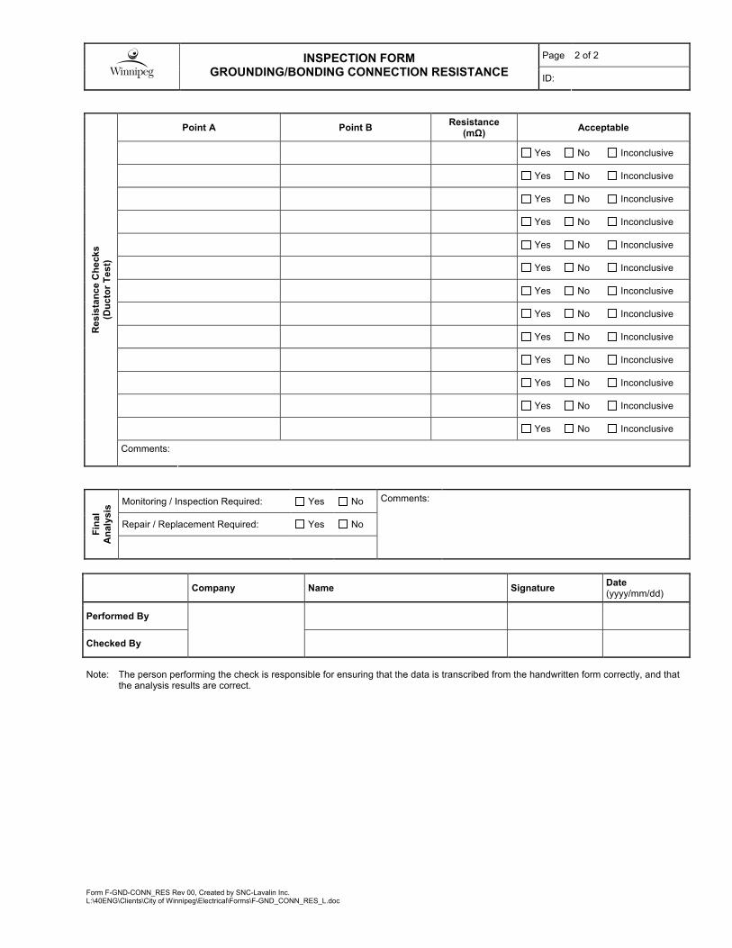
Page 2 of 2 INSPECTION FORM GROUNDING/BONDING CONNECTION RESISTANCE
ID:
Form F-GND-CONN_RES Rev 00, Created by SNC-Lavalin Inc. L:\40ENG\Clients\City of Winnipeg\Electrical\Forms\F-GND_CONN_RES_L.doc
Point A Point B Resistance
(m�) Acceptable
Yes No Inconclusive
Yes No Inconclusive
Yes No Inconclusive
Yes No Inconclusive
Yes No Inconclusive
Yes No Inconclusive
Yes No Inconclusive
Yes No Inconclusive
Yes No Inconclusive
Yes No Inconclusive
Yes No Inconclusive
Yes No Inconclusive
Yes No Inconclusive
Re
sis
tan
ce
Ch
ec
ks
(Du
cto
r T
es
t)
Comments:
Monitoring / Inspection Required: Yes No
Repair / Replacement Required: Yes No
Fin
al
An
aly
sis
Comments:
Company Name Signature Date(yyyy/mm/dd)
Performed By
Checked By
Note: The person performing the check is responsible for ensuring that the data is transcribed from the handwritten form correctly, and that the analysis results are correct.

Form F-INTEL-OL Rev 00, Created by SNC-Lavalin Inc.L:\40ENG\Clients\City of Winnipeg\Forms\Electrical\F-INTEL-OL.doc
INSPECTION FORM INTELLIGENT OVERLOAD
Page 1 of 2
ID:
Pro
ject
Facility: Project Name:
Area : Bid Opportunity:
O/L
Data
Location: Cell #:
Manufacturer: Model:
Vis
ual
Insp
ecti
on
/ C
lean
ing General Condition: Good Acceptable Poor
Cleanliness (as found) Good Acceptable Poor Unit Cleaned: Yes
Connections (as found) Good Acceptable Poor Connections Torqued: Yes
Co
mm
un
icati
on
Sett
ing
s
Static IP Address: Subnet Mask
Gateway: Protocol:
MAC Address:
Test
Mete
r Manufacturer: Model:
Calibration Date: Meter calibration must be within one year, unless otherwise specified.
CT
s
Type: Internal to O/L External External CT Ratio:
External Ground CT: Yes No Ground CT Ratio:

INSPECTION FORM INTELLIGENT OVERLOAD
Page 2 of 2
ID:
Form F-INTEL-OL Rev 00, Created by SNC-Lavalin Inc.L:\40ENG\Clients\City of Winnipeg\Forms\Electrical\F-INTEL-OL.doc
Accu
racy
Verify accuracy of Intelligent O/L Measurements with the use of software via the communication network. C
urr
en
t
Nominal Test Value
(A) Phase
Calibrated Meter Measurement
(A)
Intelligent O/LMeasurement
(A)
Difference (A)
Error (%)
Acceptable (See Specs)
0
A Yes No
B Yes No
C Yes No
A Yes No
B Yes No
C Yes No
Measurements Applicable To: As-Found As-Left May check both boxes if applicable.
Unit Calibration Adjusted: Yes No If calibration was adjusted, complete two forms, one for as-found, the other for as-left after calibration.
Fin
al
An
aly
sis
Returned to Service: Yes No Comments:
Monitoring / Further Inspection Required:
Yes No
Repair / Replacement Required: Yes No
Company Name Signature Date (yyyy/mm/dd)
Performed By
Checked By
Note: The person performing the check is responsible for ensuring that the data is transcribed from the handwritten form correctly, and that the analysis results are correct.

Form F-MCC-600V Rev 01, Created by SNC-Lavalin Inc.L:\40ENG\Clients\City of Winnipeg\Electrical\Forms\F-MCC-600V.doc
Page 1 of 6 INSPECTION FORM MCC, 600V
ID:
Facility: Project Name: P
roje
ct
Area : Bid Opportunity:
Location: # of Cells:
Manufacturer: Model: Serial #:
Rated Voltage: V Main Bus Rating: A Main Bus Neutral Rating: A
MC
C D
ata
Bus Conductor: Copper Aluminum Current Withstand Rating: A
Identification Tag Installed: Yes No Visual Signs of Overheating: Yes No
Visual Signs of Moisture: Yes No Visual Signs of Corona: Yes No
Fuse/Breaker Sizes Match Drawings: Yes No PT and CT ratios match drawings: N/A Yes No
Elevation Drawings Correct: Yes No Cables Supported Appropriately: Yes No
Cleanliness (As Found): Good Acceptable Poor Insulators Condition: Good Acceptable Poor
Connections: Good Acceptable PoorElectro/Mechanical Interlock System:
Good Acceptable Poor
Ground Connection: Good Acceptable Poor Vents/Filters: Good Acceptable Poor
Doors Mechanical: Good Acceptable Poor Exercise Active Components: Yes No
Cell Fit and Alignment: Good Acceptable Poor
Required Clearances are Met:
Good Acceptable Poor
Indicating mechanisms: Good Acceptable Poor Unit Cleaned: Yes Photograph Taken: Yes
Vis
ua
l In
sp
ec
tio
n /
Cle
an
ing
Comments:
Type: Inspection
Main Breaker Complete appropriate breaker inspection form.
Disconnect Complete appropriate disconnect inspection form.
Visual Inspection: Good Acceptable Poor
Connections Torqued: Yes
A B C N
Inc
om
ing
Po
we
r
Main Lugs
Connection Resistance (��) As Left

Page 2 of 6 INSPECTION FORM MCC, 600V
ID:
Form F-MCC-600V Rev 01, Created by SNC-Lavalin Inc.L:\40ENG\Clients\City of Winnipeg\Electrical\Forms\F-MCC-600V.doc
Test Preparation:
Source: Disconnected Connected with Source
Isolated
Cable Dest. / Load: Disconnected Connected with Load Isolated
Note: Approval of City’s Representative is required, prior to leaving cables connected during the test.
Temperature: °C
Insulation Resistance (M�) Phase To Phase
Test Summary Test Voltage
(dc) A - B B - C C - A
1000 V
Insulation Resistance (M�) Phase To GNDTest
Voltage A - GND B - GND C - GND
1000 V
Test Passed Test Inconclusive
Further Investigation Required. Test Failed
Ins
ula
tio
n R
es
ista
nc
e T
es
t
(Bu
sw
ork
)
Comments:
Test Summary Point A Point B
Resistance (��)
MCC GND Bus Facility Ground Electrode
MCC GND Bus MCC Enclosure
MCC GND Bus System Neutral
Test Passed Test Inconclusive
Further Investigation Required. Test Failed
Gro
un
d R
es
ista
nc
e
Ch
ec
ks
(D
uc
tor
Te
st)
Comments:
Visual Inspect Requirements: G=Good, A=Acceptable, P=Poor Comments are required for all items identified in Poor condition.
1. Confirm identification tag / lamacoid is installed.
2. Look for visual signs of overheating.
3. Inspect and torque connections.
4. Inspect and test any electro/mechanical interlocks.
5. Confirm disconnect operation.
6. Check door mechanical condition.
7. Exercise circuit breaker.
8. Confirm cables are supported and routed appropriately.
9. Visually assess the general condition of the installation.
Note: Complete an appropriate Breaker Inspection Form for all breakers with separate adjustable Long and Short trip settings, Ground trip settings, or > 250A frame size.
Fe
ed
er
Bre
ak
ers
Continued on next page
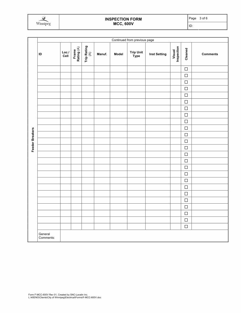
Page 3 of 6 INSPECTION FORM MCC, 600V
ID:
Form F-MCC-600V Rev 01, Created by SNC-Lavalin Inc.L:\40ENG\Clients\City of Winnipeg\Electrical\Forms\F-MCC-600V.doc
Continued from previous page
ID Loc./Cell
Fra
me
Ra
tin
g (
A)
Tri
p R
ati
ng
(A)
Manuf. Model Trip Unit
Type Inst Setting
Vis
ua
l
Ins
pe
cti
on
Cle
an
ed
Comments
Fe
ed
er
Bre
ak
ers
General Comments:

Page 4 of 6 INSPECTION FORM MCC, 600V
ID:
Form F-MCC-600V Rev 01, Created by SNC-Lavalin Inc.L:\40ENG\Clients\City of Winnipeg\Electrical\Forms\F-MCC-600V.doc
Overcurrent Protection Type: B=Breaker (Thermal Magnetic), M=breaker(Motor Circuit Protector), F=Fuse
Overload Protection Type: T=Thermal, SS=Solid State
Visual Inspect Requirements: G=Good, A=Acceptable, P=Poor Comments are required for all items identified in Poor condition.
1. Confirm identification tag / lamacoid is installed.
2. Look for visual signs of overheating.
3. Inspect and torque connections.
4. Inspect and test any electro/mechanical interlocks.
5. Confirm disconnect operation.
6. Check door mechanical condition.
7. Exercise circuit breaker.
8. Confirm cables are supported and routed appropriately.
9. Visually assess the general condition of the installation.
Mo
tor
Sta
rte
rs /
Co
nta
cto
rs
Note: Complete a Motor Starter Inspection Form for all Motor Starters Size 4 or larger, with VFDs, or with Soft Starters.
Overcurrent Protection Contactor Overload
ID Loc./ Cell
Ty
pe
Ra
tin
g (
A)
Manuf. Model Size /
Rating Ty
pe
Model
Vis
ua
l In
sp
.
Cle
an
ed
Comments
Mo
tor
Sta
rte
rs /
Co
nta
cto
rs
General Comments:

Page 5 of 6 INSPECTION FORM MCC, 600V
ID:
Form F-MCC-600V Rev 01, Created by SNC-Lavalin Inc.L:\40ENG\Clients\City of Winnipeg\Electrical\Forms\F-MCC-600V.doc
Overcurrent Protection Contactor Overload
ID Loc./ Cell
Ty
pe
Ra
tin
g (
A)
Manuf. Model Size /
Rating Ty
pe
Model
Vis
ua
l In
sp
.
Cle
an
ed
Comments
Mo
tor
Sta
rte
rs
General Comments:

Page 6 of 6 INSPECTION FORM MCC, 600V
ID:
Form F-MCC-600V Rev 01, Created by SNC-Lavalin Inc.L:\40ENG\Clients\City of Winnipeg\Electrical\Forms\F-MCC-600V.doc
Returned to Service: Yes No
Monitoring / Inspection Required: Yes No
Fin
al
An
aly
sis
Repair / Replacement Required: Yes No
Comments:
Company Name Signature Date (yyyy/mm/dd)
Performed By
Checked By
Note: The person(s) performing the check is responsible for ensuring that the data is transcribed from the handwritten form correctly, and that the analysis results are correct.

Form MS-FVNR-600V Rev 02, Created by SNC-Lavalin Inc. L:\40ENG\Clients\City of Winnipeg\Forms\Electrical\F-MS-FVNR-600V.doc
INSPECTION FORM MOTOR STARTER, FVNR, 600V
Page 1 of 2
ID:
Pro
ject
Facility: Project Name:
Area : Bid Opportunity:
Sta
rter
Data
Load: Starter Location: Cell #:
Manufacturer: Type: Serial #:
Size: Rated Voltage: V Current Rating: A Control Voltage: V
Circuit Protection:
Fused Disc. Rating: A Fuse Size: AFuse Mfg.
Model:
Breaker MCP
Rating: A Inst. Setting:
AManufacturer:
Model:
Overload Protection:
Thermal Electronic Intelligent
Class:
10 20 30 Unknown
Setting / Rating:
A
Manufacturer:
Model:
Control Power Transformer:
Size: VA Sec. Voltage: V Primary Fuse: A Secondary Fuse: A
Current Transformers:
Phases: A B C
None Ratio: Ground Fault CT:
Present Not Present
Ratio:
Mo
tor
Data
ID: Size: kW / HP Voltage: V
Full Load Amps: A Service Factor: Other:
Vis
ual In
sp
ecti
on
/ C
lean
ing
Starter Identification Tag Installed: Yes No Visual Signs of Overheating: Yes No
Cleanliness (As Found): Good Acceptable Poor Support Insulators: Good Acceptable Poor
Connections Good Acceptable PoorElectro/Mechanical Interlock:
N/A Good Acceptable Poor
Ground Connection: Good Acceptable Poor Contactor Condition: Good Acceptable Poor
Door Mechanical Good Acceptable Poor Contact Alignment: Good Acceptable Poor
Verify O/L element is correctly sized for the load:
Yes No Exercise Circuit Breaker/MCP/Disconnect Yes
Cables Supported Appropriately: Yes No Unit Cleaned: Yes Photograph Taken: Yes
Comments:
Co
nta
ct/
Po
le
Measu
rem
en
ts
Test A B C Test Summary
Test Passed Test Inconclusive
Further Investigation Required. Test Failed
Contact Resistance (µ�)
Disconnect / Breaker / MCP Resistance (µ�)
Fuse Resistance (µ�)
Comments:

INSPECTION FORM MOTOR STARTER, FVNR, 600V
Page 2 of 2
ID:
Form MS-FVNR-600V Rev 02, Created by SNC-Lavalin Inc. L:\40ENG\Clients\City of Winnipeg\Forms\Electrical\F-MS-FVNR-600V.doc
Insu
lati
on
Resis
tan
ce T
est
Test Preparation: Source: Isolated Contactor: Open
Cable Dest. / Load: Disconnected Connected with Load Isolated
Note: Approval of City’s Representative is required, prior to leaving cables connected during the test.
Test Voltage
Insulation Resistance (M�) Ground all phases not
under test! A B C
Contactor Line To GND 1000 VDC Test Summary Test Passed Test Inconclusive
Further Investigation Required.
Test Failed
Contactor Load To GND 1000 VDC
Contactor Line to Load 1000 VDC
Comments:
Fin
al
An
aly
sis
Returned to Service: Yes No Comments:
Monitoring / Further Inspection Required:
Yes No
Repair / Replacement Required: Yes No
Company Name Signature Date (yyyy/mm/dd)
Performed By
Checked By
Note: The person performing the check is responsible for ensuring that the data is transcribed from the handwritten form correctly, and that the analysis results are correct.

Form F-MUL-STEP-CAP-600V Rev 00, Created by SNC-Lavalin Inc. L:\40ENG\Clients\City of Winnipeg\Forms\Electrical\F-MUL-STEP-CAP-600V.doc
INSPECTION FORM MULTI-STEP CAPACITOR BANK, 600V
Page 1 of 3
ID:
Pro
ject
Facility: Project Name:
Area : Bid Opportunity:
Cap
acit
or
Ban
k D
ata
Location: Switchgear/MCC: Cell #:
Manufacturer: Model: Serial #:
Total Size: VAR Smallest Step Size: VAR Rated Voltage:
# of Steps: Stage Ratios: Interrupting Rating:
Configuration: Delta Wye-Ungrounded Wye-Grounded
Insu
lati
on
Resis
tan
ce T
est
Test Preparation: Source Cables:
Disconnected Connected with Source Isolated
Note: Approval of City’s Representative is required, prior to leaving cables connected during the test.
Insulation Resistance (M�) 1000V Phase To GND
Test Summary
Test Passed Test Inconclusive
Further Investigation Required. Test Failed
A (A-B) B (B-C) C (C-A)
Incoming
Step 1
Step 2
Step 3
Step 4
Step 5
Step 6
Step 7
Step 8
Comments:
Vis
ual In
sp
ecti
on
/ C
lean
ing
Identification Tag Installed: Yes No Visual Signs of Overheating: Yes No
Cleanliness (As Found): Good Acceptable Poor Support Insulators: Good Acceptable Poor
Connections: Good Acceptable PoorElectro/Mechanical Interlock:
N/A Good Acceptable Poor
Ground Connection: Good Acceptable Poor Contactor Condition: Good Acceptable Poor
Door Mechanical: Good Acceptable Poor Contact Alignment: Good Acceptable Poor
Cables Supported Appropriately: Yes No Exercise Circuit Breaker(s)/Disconnect: Yes
Unit Cleaned: Yes Photograph Taken: Yes
Comments:

INSPECTION FORM MULTI-STEP CAPACITOR BANK, 600V
Page 2 of 3
ID:
Form F-MUL-STEP-CAP-600V Rev 00, Created by SNC-Lavalin Inc. L:\40ENG\Clients\City of Winnipeg\Forms\Electrical\F-MUL-STEP-CAP-600V.doc
Cap
acit
an
ce
Step #
Capacitance (�F) Test Summary
A (A-B) B (B-C) C (C-A) Test Passed Test Inconclusive
Further Investigation Required. Test Failed
1
2
3
4
5
6
7
8
Comments:
Dis
ch
arg
e R
esis
tan
ce
Step #
Resistance (�) Test Summary
A (A-B) B (B-C) C (C-A) Test Passed Test Inconclusive
Further Investigation Required. Test Failed
1
2
3
4
5
6
7
8
Comments:

INSPECTION FORM MULTI-STEP CAPACITOR BANK, 600V
Page 3 of 3
ID:
Form F-MUL-STEP-CAP-600V Rev 00, Created by SNC-Lavalin Inc. L:\40ENG\Clients\City of Winnipeg\Forms\Electrical\F-MUL-STEP-CAP-600V.doc
Co
nta
cto
r P
ole
Measu
rem
en
ts
Contactor Resistance (µ�)
Test Summary
Test Passed Test Inconclusive
Further Investigation Required. Test Failed
A B C
Incoming
Step 1
Step 2
Step 3
Step 4
Step 5
Step 6
Step 7
Step 8
Comments:
Fin
al
An
aly
sis
Returned to Service: Yes No Comments:
Monitoring / Further Inspection Required:
Yes No
Repair / Replacement Required: Yes No
Company Name Signature Date (yyyy/mm/dd)
Performed By
Checked By
Note: The person performing the check is responsible for ensuring that the data is transcribed from the handwritten form correctly, and that the analysis results are correct.

Form F-NFDS-600V Rev 00, Created by SNC-Lavalin Inc. L:\40ENG\Clients\City of Winnipeg\Electrical\Forms\F-NFDS-600V.doc
INSPECTION FORM NON-FUSIBLE DISCONNECT SWITCH, 600V
Page 1 of 2
ID:
Pro
ject
Facility: Project Name:
Area : Bid Opportunity:
Dis
co
nn
ect
Data
Manufacturer: Model:
Rated Voltage: V Current Rating: A Interrupting Rating: A
Vis
ual In
sp
ecti
on
/ C
lean
ing
Identification Tag Installed: Yes No Visual Signs of Overheating: Yes No
Cleanliness (As Found): Good Acceptable Poor Support Insulators: Good Acceptable Poor
Connections: Good Acceptable Poor Blade Condition: Good Acceptable Poor
Ground Connection: Good Acceptable PoorVerify Blade Mechanical Operation:
Good Acceptable Poor
Door Mechanical: Good Acceptable Poor Unit Cleaned: Yes
Fit Plumb & Square: Yes No Unit Lubricated: Yes
Cables Supported Appropriately: Yes No Other:
Sw
itch
bla
de
Resis
tan
ce
Resistance (��) (As Left)
Test Summary
A B C Test Passed Test Inconclusive
Further Investigation Required. Test Failed
Comments:
Insu
lati
on
Resis
tan
ce T
est
Test Preparation: Source: Isolated Disconnect: Open
Cable Dest. / Load: Disconnected Connected with Load Isolated
Note: Approval of City’s Representative is required, prior to leaving cables connected during the test.
Test Voltage
Insulation Resistance (M�) Ground all phases not
under test! A B C
Disconnect Line To GND 1000 VDC Test Summary Test Passed Test Inconclusive
Further Investigation Required.
Test Failed
Disconnect Load To GND 1000 VDC
Disconnect Line to Load 1000 VDC
Comments:
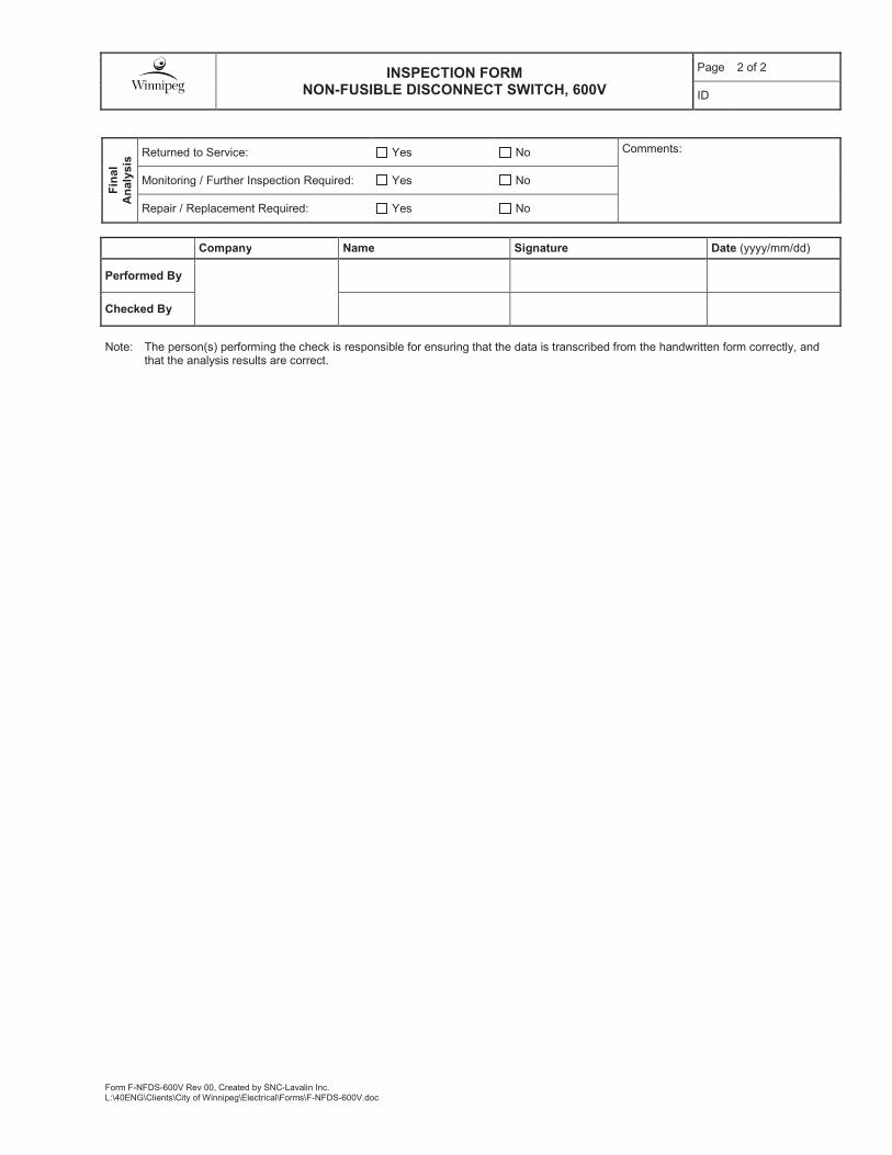
INSPECTION FORM NON-FUSIBLE DISCONNECT SWITCH, 600V
Page 2 of 2
ID
Form F-NFDS-600V Rev 00, Created by SNC-Lavalin Inc. L:\40ENG\Clients\City of Winnipeg\Electrical\Forms\F-NFDS-600V.doc
Fin
al
An
aly
sis
Returned to Service: Yes No Comments:
Monitoring / Further Inspection Required: Yes No
Repair / Replacement Required: Yes No
Company Name Signature Date (yyyy/mm/dd)
Performed By
Checked By
Note: The person(s) performing the check is responsible for ensuring that the data is transcribed from the handwritten form correctly, and that the analysis results are correct.

Form F-PNL-LV Rev 01, Created by SNC-Lavalin Inc. M:\113099\4ENG\47ELE\RA - Misc Reports & Forms\Forms\F-PNL-LV.doc
Page 1 of 2
INSPECTION FORM PANELBOARD, LOW VOLTAGE
ID:
Facility: Project Name: P
roje
ct
Area : Bid Opportunity:
Location: Fed From: No. of Circuits:
Manufacturer: Model: Serial No:
Rated Voltage: V Current Rating: A Withstand Rating: A
Single Phase 3 Phase, 3 Wire 3 Phase, 4 Wire Neutral Bonded to Ground Yes No
Main Lugs
Main Breaker: Rating: A Manufacturer: Model: Inst. Setting:
Pan
elb
oard
Data
Complete separate inspection form (F-BKR-MC-LV) for main breaker if >= 250A, or has long, short, or ground fault settings.
Identification Tag Installed: Yes No Visual Signs of Overheating: Yes No
Visual signs of Moisture: Yes No Visual Signs of Corona: Yes No
Fuse/Breaker Sizes Match Drawings: Yes No Cables Supported Appropriately: Yes No
Cleanliness (As Found): Good Acceptable Poor Connections: Good Acceptable Poor
Door Mechanical: Good Acceptable Poor Ground Connection: Good Acceptable PoorVis
ual In
sp
ecti
on
/
Cle
an
ing
Exercise All Circuit Breakers: Yes No Comments:
Equipment Temperature: °C Test Preparation:
Source: Disconnected Connected with
Source Isolated
Note: Approval of City’s Representative is required, prior to leaving cables connected during the test. Temperature Correction
Factor to 20°C:
Insulation Resistance (M!) Ground all Phases not under test! Test
Voltage A-GND B-GND C-GND N-GND
RDG 20°C RDG 20°C RDG 20°C RDG 20°C
Test Summary
Test Passed Test Inconclusive
Further Investigation Required. Test Failed
Test Voltages: 120-300V ! 500 VDC Test Voltage 301-600V ! 1000 VDC Test Voltage Insu
lati
on
Resis
tan
ce T
est
Comments:
Breakers < "00A and Without Inst. Setting
List by model of breaker. Multiple breakers of varying ampacity may be listed per line.
Type Manufacturer Model Series Interrupting Rating (kA)
Positions/Circuits Notes
A
B
C
D
E
Lo
ad
/Feed
er
Bre
akers
F

Page 2 of 2
INSPECTION FORM PANELBOARD, LOW VOLTAGE
ID:
Form F-PNL-LV Rev 01, Created by SNC-Lavalin Inc. M:\113099\4ENG\47ELE\RA - Misc Reports & Forms\Forms\F-PNL-LV.doc
Breakers >= "00A or with Inst. Setting
List each breaker individually. Complete separate inspection form (F-BKR-MC-LV) for breaker if >= 250A, or has long, short, or ground fault settings.
ID Pos. Manufacturer Model Trip
Rating (A)
Int. Rating
(kA)
Inst. Setting
Separate Form
Notes
Lo
ad
/Feed
er
Bre
akers
Returned to Service: Yes No
Monitoring / Inspection Required: Yes No
Fin
al
An
aly
sis
Repair / Replacement Required: Yes No
Comments:
Company Name Signature Date (yyyy/mm/dd)
Performed By
Checked By
Note: The person performing the check is responsible for ensuring that the data is transcribed from the handwritten form correctly, and that the analysis results are correct.
Form F-RELAY-VM-SSAC-WVM Rev 00, Created by SNC-Lavalin Inc. L:\40ENG\Clients\City of Winnipeg\Electrical\Forms\F-RELAY-VM-SSAC-WVM.doc
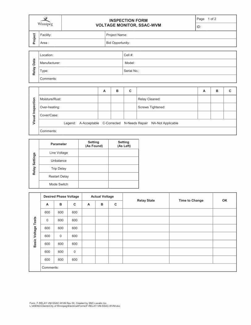
INSPECTION FORM VOLTAGE MONITOR, SSAC-WVM
Page 1 of 2
ID:
Pro
ject
Facility: Project Name:
Area : Bid Opportunity:
Rela
y D
ata
Location: Cell #:
Manufacturer: Model:
Type: Serial No.:
Comments:
Vis
ual In
sp
ecti
on
A B C A B C
Moisture/Rust: Relay Cleaned:
Over-heating: Screws Tightened:
Cover/Case:
Legend: A-Acceptable C-Corrected N-Needs Repair NA-Not Applicable
Comments:
Rela
y S
ett
ing
s
Parameter Setting
(As Found) Setting
(As Left)
Line Voltage
Unbalance
Trip Delay
Restart Delay
Mode Switch
Basic
Vo
ltag
e T
ests
Desired Phase Voltage Actual Voltage
Relay State Time to Change OK
A B C A B C
600 600 600
0 600 600
600 600 600
600 0 600
600 600 600
600 600 0
600 600 600
Comments:

INSPECTION FORM VOLTAGE MONITOR, SSAC-WVM
Page 2 of 2
ID:
Form F-RELAY-VM-SSAC-WVM Rev 00, Created by SNC-Lavalin Inc. L:\40ENG\Clients\City of Winnipeg\Electrical\Forms\F-RELAY-VM-SSAC-WVM.doc
Fin
al
An
aly
sis
Returned to Service: Yes No Comments:
Monitoring / Further Inspection Required:
Yes No
Repair / Replacement Required: Yes No
Company Name Signature Date (yyyy/mm/dd)
Performed By
Checked By
Note: The person(s) performing the check is responsible for ensuring that the data is transcribed from the handwritten form correctly, and that the analysis results are correct.

Form F-SWB-600V Rev 00, Created by SNC-Lavalin Inc.M:\113099\4ENG\47ELE\RA - Misc Reports & Forms\Forms\F-SWB-600V.doc
Page 1 of 4 INSPECTION FORM SWITCHBOARD, 600V
ID:
Facility: Project Name: P
roje
ct
Area : Bid Opportunity:
Location: # of Cells:
Manufacturer: Model: Serial #:
Rated Voltage: V Main Bus Rating: A Main Bus Neutral Rating: A
SW
B D
ata
Bus Conductor: Copper Aluminum Current Withstand Rating: A
Identification Tag Installed: Yes No Visual Signs of Overheating: Yes No
Visual Signs of Moisture: Yes No Visual Signs of Corona: Yes No
Fuse/Breaker Sizes Match Drawings: Yes No PT and CT ratios match drawings: Yes No
Elevation Drawings Correct: Yes No Cables Supported Appropriately: Yes No
Cleanliness (As Found): Good Acceptable Poor Insulators Condition: Good Acceptable Poor
Connections: Good Acceptable PoorElectro/Mechanical Interlock System:
Good Acceptable Poor
Ground Connection: Good Acceptable Poor Vents/Filters: Good Acceptable Poor
Doors Mechanical: Good Acceptable Poor Exercise Active Components: Yes No
Cell Fit and Alignment: Good Acceptable Poor
Required Clearances are Met:
Good Acceptable Poor
Indicating mechanisms: Good Acceptable Poor Unit Cleaned: Yes Photograph Taken: Yes
Vis
ua
l In
sp
ec
tio
n /
Cle
an
ing
Comments:
Type: Inspection
Main Breaker Complete appropriate breaker inspection form.
Disconnect Complete appropriate disconnect inspection form.
Visual Inspection: Good Acceptable Poor
Connections Torqued: Yes
A B C N
Inc
om
ing
Po
we
r
Main Lugs
Connection Resistance (��) As Left

Page 2 of 4 INSPECTION FORM SWITCHBOARD, 600V
ID:
Form F-SWB-600V Rev 00, Created by SNC-Lavalin Inc.M:\113099\4ENG\47ELE\RA - Misc Reports & Forms\Forms\F-SWB-600V.doc
Test Preparation:
Source: Disconnected Connected with Source
Isolated
Cable Dest. / Load: Disconnected Connected with Load Isolated
Note: Approval of City’s Representative is required, prior to leaving cables connected during the test.
Temperature: °C
Insulation Resistance (M�) Phase To Phase
Test Summary Test Voltage
(dc) A - B B - C C - A
1000 V
Insulation Resistance (M�) Phase To GNDTest
Voltage A - GND B - GND C - GND
1000 V
Test Passed Test Inconclusive
Further Investigation Required. Test Failed
Ins
ula
tio
n R
es
ista
nc
e T
es
t
(Bu
sw
ork
)
Comments:
Test Summary Point A Point B
Resistance (��)
SWB GND Bus Facility Ground Electrode
SWB GND Bus SWB Enclosure
SWB GND Bus System Neutral
Test Passed Test Inconclusive
Further Investigation Required. Test Failed
Gro
un
d R
es
ista
nc
e
Ch
ec
ks
(D
uc
tor
Te
st)
Comments:
Visual Inspect Requirements: G=Good, A=Acceptable, P=Poor Comments are required for all items identified in Poor condition.
1. Confirm identification tag / lamacoid is installed.
2. Look for visual signs of overheating.
3. Inspect and torque connections.
4. Inspect and test any electro/mechanical interlocks.
5. Confirm disconnect operation.
6. Check door mechanical condition.
7. Exercise circuit breaker.
8. Confirm cables are supported and routed appropriately.
9. Visually assess the general condition of the installation.
Note: Complete an appropriate Breaker Inspection Form for all breakers with separate adjustable Long and Short trip settings, Ground trip settings, or > 250A frame size.
Fe
ed
er
Bre
ak
ers
Continued on next page

Page 3 of 4 INSPECTION FORM SWITCHBOARD, 600V
ID:
Form F-SWB-600V Rev 00, Created by SNC-Lavalin Inc.M:\113099\4ENG\47ELE\RA - Misc Reports & Forms\Forms\F-SWB-600V.doc
Continued from previous page
ID Loc./Cell
Fra
me
Ra
tin
g (
A)
Tri
p R
ati
ng
(A)
Manuf. Model Trip Unit
Type Inst Setting
Vis
ua
l
Ins
pe
cti
on
Cle
an
ed
Comments
Fe
ed
er
Bre
ak
ers
General Comments:

Page 4 of 4 INSPECTION FORM SWITCHBOARD, 600V
ID:
Form F-SWB-600V Rev 00, Created by SNC-Lavalin Inc.M:\113099\4ENG\47ELE\RA - Misc Reports & Forms\Forms\F-SWB-600V.doc
Returned to Service: Yes No
Monitoring / Inspection Required: Yes No
Fin
al
An
aly
sis
Repair / Replacement Required: Yes No
Comments:
Company Name Signature Date (yyyy/mm/dd)
Performed By
Checked By
Note: The person(s) performing the check is responsible for ensuring that the data is transcribed from the handwritten form correctly, and that the analysis results are correct.

Form F-XFMR-DRY-LV Rev 02, Created by SNC-Lavalin Inc. L:\40ENG\Clients\City of Winnipeg\Electrical\Forms\F-XFMR-DRY-LV.doc
Page 1 of 2 INSPECTION FORM TRANSFORMER, DRY TYPE, LOW VOLTAGE
ID:
Facility: Project Name: P
roje
ct
Area : Bid Opportunity:
KVA: Phase: Primary Voltage: VSecondary Voltage:
V
Manufacturer: Type: Serial Number:
Primary Winding:
�
�
Secondary Winding:
�
�Impedance: %Z Temp Rise: °C K Factor:
Winding Material: Copper Aluminum
Tap 1 2 3 4 5 Tra
ns
form
er
Da
ta
No Load Tap Changer
Voltage
Tap Setting (As Found):
Transformer Identification Tag Installed: Yes No Visual Signs of Overheating: Yes No
Bushings: Good Acceptable Poor Support Insulators: Good Acceptable Poor
Paint: Good Acceptable PoorNo Load Tap Changer:
N/A Good Acceptable Poor
Fans: N/A Good Acceptable Poor Fan Controls: N/A Good Acceptable Poor
Temp. Gauge: N/A Good Acceptable Poor Connections: Good Acceptable Poor
Ground Connection:
Good Acceptable Poor Neutral Bonded to Ground: N/A Yes No
Vis
ua
l In
sp
ec
tio
n /
Cle
an
ing
Cleanliness (As Found): Good Acceptable Poor Unit Cleaned: Yes Photograph Taken: Yes
Operational Conditions / Notes:
Primary Voltage: H1:H2: V H2:H3: V H3:H1: V Measured at:
Secondary Voltage: X1:__: V X2:__: V X3:__: V Measured at:
Current: Ph A: A Ph B: A Ph C: A Measured at:
Tap Setting: Appears Satisfactory Further Monitoring Recommended. Recommend Changing Tap.
Tap Setting (As Left):
Op
era
tio
na
l In
sp
ec
tio
n
Thermographic Inspection Performed:
Yes Attach report separately
Results: No Issues Found Potential Issue Identified.
Resistance (M�)
Winding Test Voltage
(Vdc) 30 sec 60 sec.
Dielectric Absorption Ratio
60s/30s
Primary to Ground, Secondary Guarded
Secondary to Ground, Primary Guarded
Ins
ula
tio
n R
es
ista
nc
e
Primary to Secondary, Ground Guarded

Page 2 of 2 INSPECTION FORM TRANSFORMER, DRY TYPE, LOW VOLTAGE
ID:
Form F-XFMR-DRY-LV Rev 02, Created by SNC-Lavalin Inc. L:\40ENG\Clients\City of Winnipeg\Electrical\Forms\F-XFMR-DRY-LV.doc
Returned to Service: Yes No
Monitoring / Further Inspection Required:
Yes No
Fin
al
An
aly
sis
Repair / Replacement Required: Yes No
Comments:
Company Name Signature Date (yyyy/mm/dd)
Performed By
Checked By
Note: The person(s) performing the check is responsible for ensuring that the data is transcribed from the handwritten form correctly, and that the analysis results are correct.

Form F-XFMR-DRY-MV Rev 01, Created by SNC-Lavalin Inc. L:\40ENG\Clients\City of Winnipeg\Electrical\Forms\F-XFMR-DRY-MV.doc
Page: 1 of 3 INSPECTION FORM TRANSFORMER, DRY TYPE, MEDIUM VOLTAGE
ID:
Facility: Project Name: P
roje
ct
Area : Bid Opportunity:
KVA: Phase: Primary Voltage: V Secondary Voltage: V
Manufacturer: Model: Serial Number:
Primary Winding:
�
�
Secondary Winding:
�
�Impedance: %Z Temp Rise: °C K Factor:
Cooling: ANN ANF
# Cooling Fans: Winding Material:
Tap 1 2 3 4 5 Tra
ns
form
er
Da
ta
No Load Tap Changer
Voltage
Tap Setting (As Found):
Transformer Identification Tag Installed: Yes No Visual Signs of Overheating: Yes No
Bushings: Good Acceptable Poor Support Insulators: Good Acceptable Poor
Paint: Good Acceptable PoorNo Load Tap Changer:
N/A Good Acceptable Poor
Fans: N/A Good Acceptable Poor Fan Controls: N/A Good Acceptable Poor
Temp. Gauge: N/A Good Acceptable Poor Connections: Good Acceptable Poor
Ground Connection:
Good Acceptable Poor Ground Conductor Size:
Vis
ua
l In
sp
ec
tio
n /
Cle
an
ing
Cleanliness (As Found): Good Acceptable Poor Unit Cleaned: Yes Photograph Taken: Yes
Operational Conditions / Notes:
Primary Voltage: H1:H2: V H2:H3: V H3:H1: V Measured at:
Secondary Voltage: X1:__: V X2:__: V X3:__: V Measured at:
Current: Ph A: A Ph B: A Ph C: A Measured at:
Tap Setting: Appears Satisfactory Further Monitoring Recommended. Recommend Changing Tap.
Tap Setting (As Left):
Op
era
tio
na
l In
sp
ec
tio
n
Thermographic Inspection Performed:
Yes Attach report separately
Results: No Issues Found Potential Issue Identified.

Page: 2 of 3 TRANSFORMER INSPECTION FORM DRY TYPE, MEDIUM VOLTAGE
ID:
Form F-XFMR-DRY-MV Rev 00, Created by SNC-Lavalin Inc. L:\40ENG\Clients\City of Winnipeg\Electrical\Forms\F-XFMR-DRY-MV.doc
Winding Temperature: oC Temperature Correction Factor (20
oC):
Resistance (M�)
PRI-GND SEC-GND PRI-SEC
Test Voltage: Test Voltage: Test Voltage: Time
Reading Corrected to
20oC
Reading Corrected to
20oC
Reading Corrected to
20oC
1 min.
2 min.
3 min.
4 min.
5 min.
6 min.
7 min.
8 min.
9 min.
10 min.
Ins
ula
tio
n R
es
ista
nc
e
PolarizationIndex
Winding Temperature: oC
Winding Winding Resistance (m�) Winding Winding Resistance (m�)
H2 – H1 X0 – X1
H3 – H2 X0 – X2
Win
din
g R
es
ista
nc
e
H3 – H1 X0 – X3
Measured Ratios Tap (Designated)
Primary Voltage (V)
Secondary Voltage (V)
Calculated Ratio
H3 H1 / X0 X1 H1 H2 / X0 X2 H2 H3 / X0 X3
Tu
rns
Ra
tio
Te
st
Note: Torque check required for all cables. Connection Resistance Test required for cables 250MCM or larger.
Connection Resistance (��) - As Left Termination
A B C N
Torque Check
Source OK Co
nn
ec
tio
n
Re
sis
tan
ce
Dest. / Load OK

Page: 3 of 3 TRANSFORMER INSPECTION FORM DRY TYPE, MEDIUM VOLTAGE
ID:
Form F-XFMR-DRY-MV Rev 00, Created by SNC-Lavalin Inc. L:\40ENG\Clients\City of Winnipeg\Electrical\Forms\F-XFMR-DRY-MV.doc
Returned to Service: Yes No
Monitoring / Further Inspection Required:
Yes No
Fin
al
An
aly
sis
Repair / Replacement Required: Yes No
Comments:
Company Name Signature Date (yyyy/mm/dd)
Performed By
Checked By
Note: The person performing the check is responsible for ensuring that the data is transcribed from the handwritten form correctly, and that the analysis results are correct.