insp (inter-network service protection) characteristics ... · slide 1 insp (inter-network service...
TRANSCRIPT
Slide 1
INSP (Inter-Network Service Protection) Characteristics and Mechanism
Zehavit AlonJuly 2010

Slide 2
Preface
• The IEEE802 1 interworking task group started work on an NNI protection solution.
• This presentation: – Lists the main characteristics of the Inter-Network Service Protection
(INSP) mechanism .– Elaborates on the INSP mechanism
Slide 3
INSP characteristics (1)
• Protects against any single failure or degradation of a link or a node. May support some multi-failure cases.
• Protection time is less than 50ms including failure detection.• Protects a VLAN or group of VLANs. Each VLAN can use a different
border node as its SG (Service Gateway) and take a different route. However, all specific VLAN traffic will use the same route, therefore a service will never be split between interfaces
• Isolates a link failure (when possible, i.e. in full-mesh constructs) and prevents propagation of the failure to the attached networks. Only node-related protection events affect the network to which the node belongs.
• The INSP mechanism operates in isolation; a failure in the interconnected zone is handled solely by the interconnected zone. A failure in any of the attached networks is independent and has no impact on the interconnected zone (unless the failure occurs in a border node that is shared by a network and the interconnected zone).
Slide 4
INSP characteristics (2)
• Ensures that a VLAN (or group of VLANs) enters and leaves a network via one and the same border node. This border node is the Service Gateway (SG)
• Ensures that the service is co-routed in the interconnected zone• Operates on the MEF-defined external interfaces (EIs): UNI and E-NNI• Supports interconnection between different network types (e.g. CN-PBN,
PBN-PBN, PBN-PBBN, PBBN-PBBN, etc.) provided that the protected interface is a MEF EI
• Provides a clear indication of the protection state• Independent protocol. Does not depend on the network capabilities and
thus does not need to modify protocols running inside each of the interconnected networks
Slide 5
INSP characteristics (3)
• Maintains an agnostic approach regarding: – the network technology running in each of the interconnected networks, and– any protection mechanism deployed by each of the interconnected networks
• Each VLAN is protected independently, therefore different VLANs can use different nodes and links. This capability enables load-balancing between the interfaces that connect the networks and ensures more efficient utilization of resources
• Supports partial and full-mesh constructs and is configured in a way that enables the operator to detect the path that VLAN traffic will use following any type of failure. This capability ensures determinism and predictability.
• Failure is detected by link-level OAM messages. Each OAM message contains information on all VLANs, i.e. one message for up to 4K services.
• Provides the shortest delay, since the INSP mechanism selects the shortest path between SGs

Slide 6
Interconnected Zone
Operator 1 Network
INSP - Inter Network Service Protection
Operator 2 Network
INSP provides service protection over NNIsINSP components comprise: • Border nodes that are responsible for conveying services from the network to the
interconnected zone, and from the interconnected zone to the network– Border nodes in each network are clustered in service portals (SP)
• External links connecting border nodes between SPs• Internal links connect border nodes inside an SP
External link
Internal linkBorder node
Service Portal
Slide 7
Node types
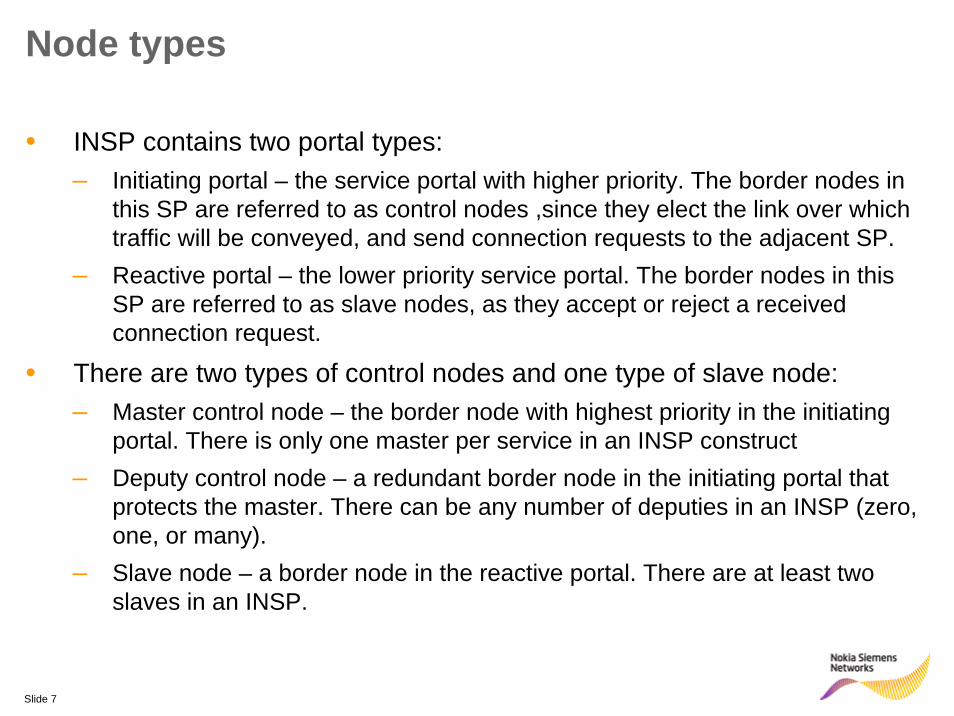
• INSP contains two portal types:– Initiating portal – the service portal with higher priority. The border nodes in
this SP are referred to as control nodes ,since they elect the link over which traffic will be conveyed, and send connection requests to the adjacent SP.
– Reactive portal – the lower priority service portal. The border nodes in this SP are referred to as slave nodes, as they accept or reject a received connection request.
• There are two types of control nodes and one type of slave node:– Master control node – the border node with highest priority in the initiating
portal. There is only one master per service in an INSP construct– Deputy control node – a redundant border node in the initiating portal that
protects the master. There can be any number of deputies in an INSP (zero, one, or many).
– Slave node – a border node in the reactive portal. There are at least two slaves in an INSP.

Slide 8
Operator 2 Network
Operator 1 Network
INSP – Principles of OperationRoute creation
• The preferred link is the external link connecting the SG of both portals. Connectivity is direct and follows the shortest path between the SGs.
• If this link is not available, another external link is used.• A non-SG border node uses the internal link to forward traffic
to the SG of its portal. This route is indirect and involves an intermediate border node.

Slide 9
Possible route types
DirectThe SGs are connected directly by an external link.
A failure of one of the SGs will result in a new direct connection between the new SG and the remote SG. A failure of the external link lead to the creation of a bypass that will preserve the SGs
IndirectThe SGs are connected indirectly by an external link, an intermediate border node and an internal link. The indirect route is called a bypass
A failure of any of the bypass components causes the whole bypass to shut down, (as a bypass is useful only when it is unbroken) and a new direct connectivity between the SGs is created.

Slide 10
INSP messages
• Each port on a border node participating in the INSP mechanism sends/receives to/from the link the following data per VLAN:
– the node state which can be (1) service gateway or (2) standby– the port state which can be (1) active or (2) standby
• The possible combinations of node states and port states are:
FunctionalityInitials
Node is SG (conveys traffic to the interconnected zone) using this external port
A
O
T
S
No connectivity on this portDDown
Ab
Node is SG using another external port
Node is not SG but still receives traffic on one of the external ports and passes it to the portal SG over the internal port. This node is used as a bypass to a failed
link
TunnelActive(send and receives)
Standby
Node is not SG and does not use any port to convey traffic
The port is not configured, the link is not present
State Port Condition Border Node
ConditionActive
Operational
Standby
Absent
Active (send and receives)
Active (SG)
StandbyActive (SG)
StandbyStandby
Slide 11
Master state machine
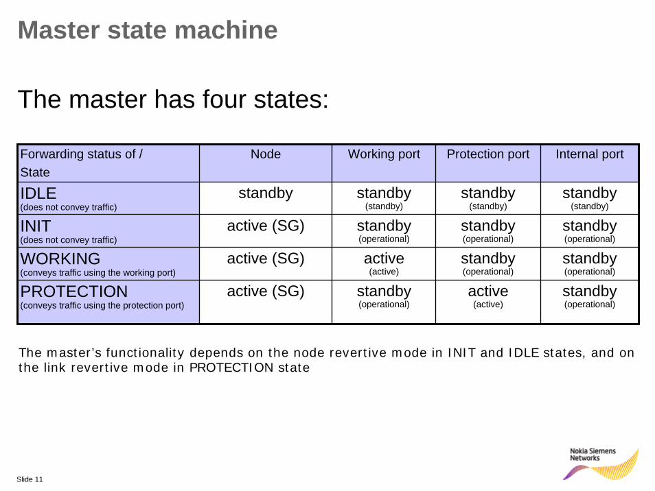
The master has four states:
Forwarding status of /State
Node Working port Protection port Internal port
IDLE (does not convey traffic)
standby standby(standby)
standby(standby)
standby(standby)
INIT(does not convey traffic)
active (SG) standby(operational)
standby(operational)
standby(operational)
WORKING(conveys traffic using the working port)
active (SG) active(active)
standby (operational)
standby(operational)
PROTECTION(conveys traffic using the protection port)
active (SG) standby(operational)
active(active)
standby(operational)
The master’s functionality depends on the node revertive mode in INIT and IDLE states, and on the link revertive mode in PROTECTION state
Slide 12
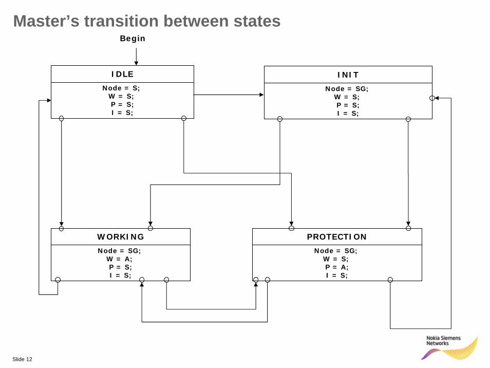
Begin
Node = S; W = S; P = S;I = S;
IDLE
Node = SG; W = A; P = S;I = S;
WORKING
Node = SG; W = S; P = A;I = S;
PROTECTION
Master’s transition between states
Node = SG; W = S; P = S;I = S;
INIT
Slide 13
Deputy state machine
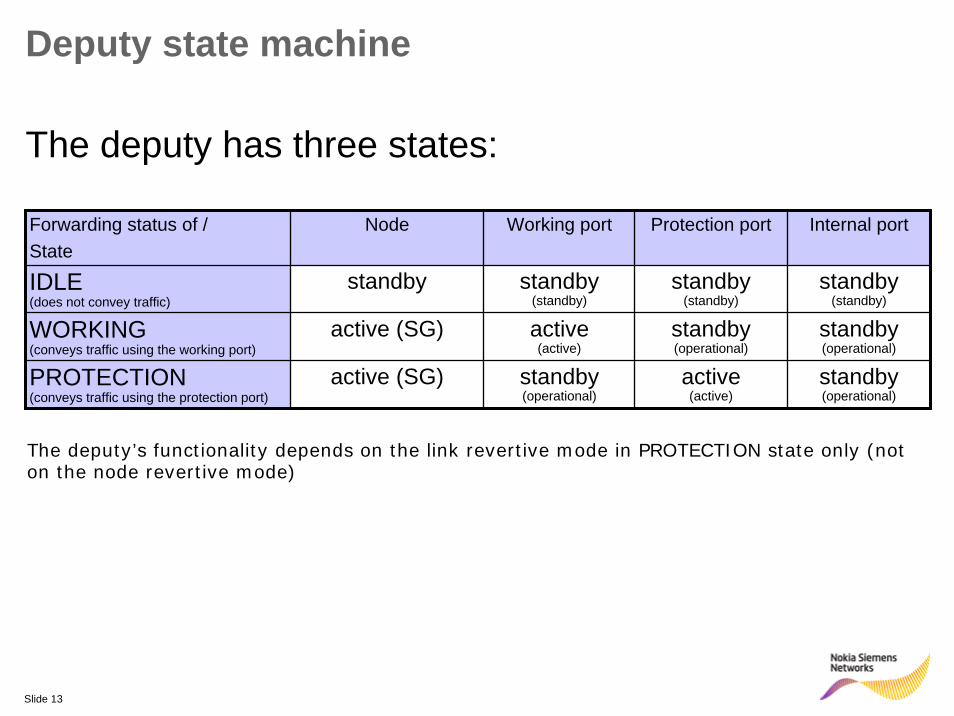
The deputy has three states:
Forwarding status of /State
Node Working port Protection port Internal port
IDLE (does not convey traffic)
standby standby(standby)
standby(standby)
standby(standby)
WORKING(conveys traffic using the working port)
active (SG) active(active)
standby (operational)
standby(operational)
PROTECTION(conveys traffic using the protection port)
active (SG) standby(operational)
active(active)
standby(operational)
The deputy’s functionality depends on the link revertive mode in PROTECTION state only (not on the node revertive mode)

Slide 14
Begin
Node = S; W = S; P = S;I = S;
IDLE
Node = SG; W = A; P = S;M = S;
WORKING
Node = SG; W = S; P = A;M= S;
PROTECTION
Deputy’s transition between states

Slide 15
Slave state machine
The slave has five states:Forwarding status ofState
Node Port Pi Port Pj Internal port
IDLE (do not convey traffic)
standby standby(standby)
standby(standby)
standby(standby)
INIT(Intermediate state to keep track of the SG do not convey traffic)
active (SG) standby(operational)
standby(operational)
standby(operational)
TUNNEL-Pi/j(Transfers traffic from/to P1 to/from the internal port )
standby active/ standby (tunnel)/(standby)
standby/active (standby)/(tunnel)
active(tunnel)
Pi/Pj(convey traffic using on of its ports)
active (SG) active/standby(active) / (operational)
standby/active(operational)/ (active)
standby(operational)
INTERNAL (convey traffic using the internal port)
active (SG) standby (operational)
standby(operational)
active(active)
The slave’s functionality does not depend on revertive mode.
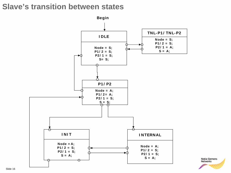
Slide 16
Begin
Node = S; P1/2 = S; P2/1 = S;
S= S;
IDLE
Node = A; P1/2 = S; P2/1 = S;
S = A;
INTERNAL
Node = A; P1/2= A; P2/1 = S;
S = S;
P1/P2
Node =A; P1/2 = S; P2/1 = S;
S = A;
INIT
Node = S; P1/2 = S; P2/1 = A;
S = A;
TNL-P1/TNL-P2
Slave’s transition between states


Slide 18
Backup slides

Slide 19
S1 failed
M failed
S2 failed || LRM && S1 recovered
D failed
D-S2 failed
M1-S1 failed
M-S1-S2
M S1
S2D
D-S1 failed
D-S2-S1
M S1
S2D
M-S1 failed ||S1-S2 failed || S1 failed
S1-S2 failed ||D-S2 failed || S2 failed
D-S1
M S1
D S2
M-S2-S1
M S1
S2D
S1 failed
D-S1-S2
M S1
S2D
M-S1
M S1
S2D
LRM && M-S1 recovered || S2 failed
M-S2
M S1
S2D
D-S2
M S1
D S2
NRM && M recovered ||D failed
M-S2 failed
D failed
S1 failed
D-S1 failed || S1-S2 failed || S1 failed
M-S2 failed || S1-S2 failed || S2 failed
M failedS1 failed
S2 failedD failed
M failed
M failed
S2 failed
Flow Chart
Slide 20
DMLinkrecovers
Link revertive mode
Mrecovers
Node revertive mode
D-S1M-S2
--
-
-
D-S2-S1
-
-
D-S2
-
M-S1
-
-
M-S1-S2
-
M-S1
-
-
-
M-S1
-
-
M-S1
M-S1-
D-S1
-
D-S1
-
D-S1
D-S1
M-DD-S2S1-S2M-S1 S2 D S1MFacility failure
State
-
-
-----M-S2-S1--M-S2 D-S1 M-S1
D-S1M-S2-D-S1-S2--D-S1M-S2--D-S2
M-S1-----M-S1 --D-S2 M-S2
-M-S1-----M-S1D-S2-D-S1
M-S1---M-S1-M-S1-M-S2D-S1M-S2-S1
----M-S2M-S2M-S1-M-S2D-S2M-S1-S2
-M-S2--D-S2-D-S1M-S2D-S2-D-S1-S2
D-S1M-S1-D-S1D-S1-D-S1M-S1D-S2-D-S2-S1
S2
M S1
D
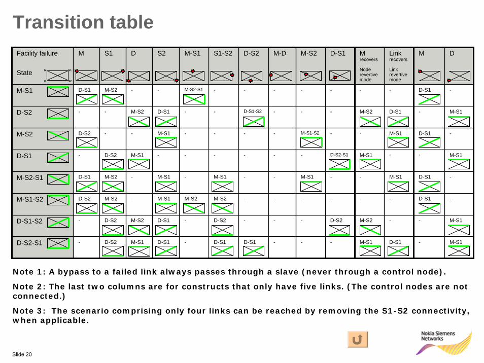
Transition table
Note 1: A bypass to a failed link always passes through a slave (never through a control node).
Note 2: The last two columns are for constructs that only have five links. (The control nodes are not connected.)
Note 3: The scenario comprising only four links can be reached by removing the S1-S2 connectivity, when applicable.

Slide 21
State machine
• The state machines of all node types are detailed in the INSP state machine.doc
• For each node type, the tables contain the state to which the machine can change and the triggers that cause this transition.
The event received on
the working
port from the peer
node
This column describes the current state of the master
Current State
Node Mode
Link Mode
RW RP RI New State Comment
S O D IDLE Link between master and deputy failed, Master took over (thought that the Deputy failed) but deputy is TG on protection. (Master should not have taken over) Slave did not change to active after WTTO, so deputy return to IDLE
S D Ab WORKING Protection failed
This column describes the node
mode: Revertive (RM) or Continued
Switched mode (CSM)
This column describes the link mode: Revertive
(RM) or Continued Switched mode
(CSM)
The event received on
the protection port from the peer
node
The event received on the
internal port from the peer
node
The new state of the master after processing the event
Explanations
The cause
Slide 22
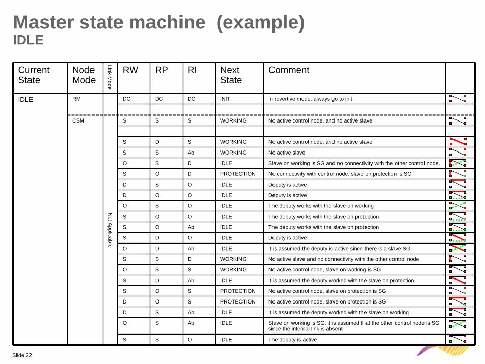
Master state machine (example)IDLE
Current State
Node Mode
Link Mode
RW RP RI Next State
Comment
DC DC DC INIT In revertive mode, always go to init
S D S WORKING No active control node, and no active slave
D S Ab IDLE It is assumed the deputy worked with the slave on working
O S Ab IDLE Slave on working is SG, it is assumed that the other control node is SG since the internal link is absent
S S S WORKING No active control node, and no active slave
S S Ab WORKING No active slave
O S D IDLE Slave on working is SG and no connectivity with the other control node.
S O D PROTECTION No connectivity with control node, slave on protection is SG
O S O IDLE The deputy works with the slave on working
S S D WORKING No active slave and no connectivity with the other control node
S O O IDLE The deputy works with the slave on protection
S O Ab IDLE The deputy works with the slave on protection
S D O IDLE Deputy is active
S S O IDLE The deputy is active
O D Ab IDLE It is assumed the deputy is active since there is a slave SG
D S O IDLE Deputy is active
D O O IDLE Deputy is active
O S S WORKING No active control node, slave on working is SG
S D Ab IDLE It is assumed the deputy worked with the slave on protection
S O S PROTECTION No active control node, slave on protection is SG
D O S PROTECTION No active control node, slave on protection is SG
CSM
Not A
pplicable
RMIDLE