insights and best practice automotive immunity
TRANSCRIPT

TECHNICAL NOTE 0102
VOLTAGE OFFSET TEST
AMETEK CTS GmbH Sternenhofstrasse 15 4153 Reinach, Switzerland [email protected]
AUTOMOTIVE IMMUNITY Insights and best practice
Author: Thomas HandschinProduct Manager - AMETEK CTS
Related standardsLV 123VW 80303VW 80300ISO 21498
The challenge
International and manufacturer standards define a set of EMC tests that must be performed on high voltage components of electric cars. During the Voltage Offset Test the insulation of the component is subjected to a DC offset voltage. The challenge is to keep the EUT supply voltage constant while the offset voltage undergoes various changes i.e. slow and fast slopes or triangular changes.
The solution
Ametek CTS offers a complete solution to performing EMC tests on electrical vehicle components. Two different methods are used to perform the voltage offset test, which are described in this applica-tion note.
AMETEK CTS GmbH Sternenhofstrasse 15 4153 Reinach, Switzerland [email protected]
AUTOMOTIVE IMMUNITY
TECHNICAL NOTE 0102
VOLTAGE OFFSET TESTInsights and best practice
Introduction
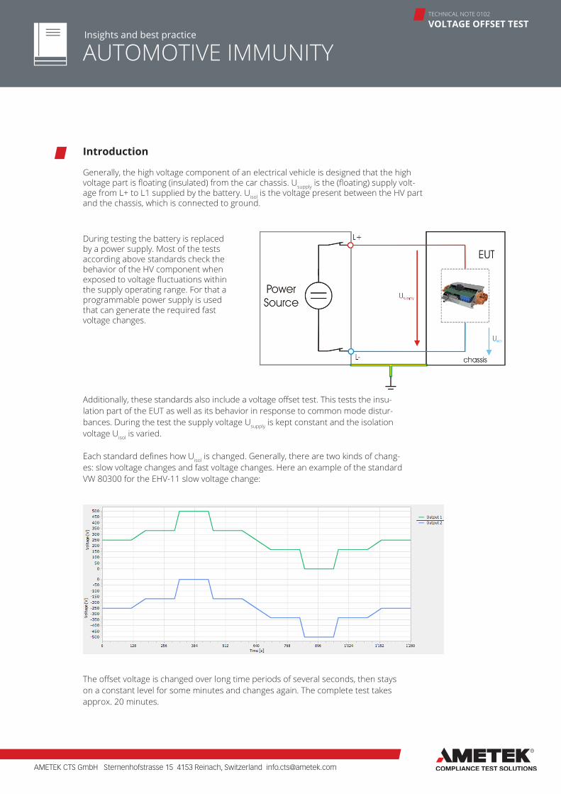
Generally, the high voltage component of an electrical vehicle is designed that the high voltage part is floating (insulated) from the car chassis. Usupply is the (floating) supply volt-age from L+ to L1 supplied by the battery. Uisol is the voltage present between the HV part and the chassis, which is connected to ground.
Additionally, these standards also include a voltage offset test. This tests the insu-lation part of the EUT as well as its behavior in response to common mode distur-bances. During the test the supply voltage Usupply is kept constant and the isolation voltage Uisol is varied.
Each standard defines how Uisol is changed. Generally, there are two kinds of chang-es: slow voltage changes and fast voltage changes. Here an example of the standard VW 80300 for the EHV-11 slow voltage change:
The offset voltage is changed over long time periods of several seconds, then stays on a constant level for some minutes and changes again. The complete test takes approx. 20 minutes.
During testing the battery is replaced by a power supply. Most of the tests according above standards check the behavior of the HV component when exposed to voltage fluctuations within the supply operating range. For that a programmable power supply is used that can generate the required fast voltage changes.
AMETEK CTS GmbH Sternenhofstrasse 15 4153 Reinach, Switzerland [email protected]
AUTOMOTIVE IMMUNITY
TECHNICAL NOTE 0102
VOLTAGE OFFSET TESTInsights and best practice
Another example from VW 80300 EHV-11 shows fast changing voltages:
The illustration above shows the overall test with a test time of approx. 6 minutes. The picture is magnified. It can be seen that it is a triangular voltage with a period of 10ms (100Hz).
There are several ways to perform the voltage offset test. Ametek CTS has imple-mented two methods in their NetWave power sources, which will be explained in the following chapters.
Method with 2 sources
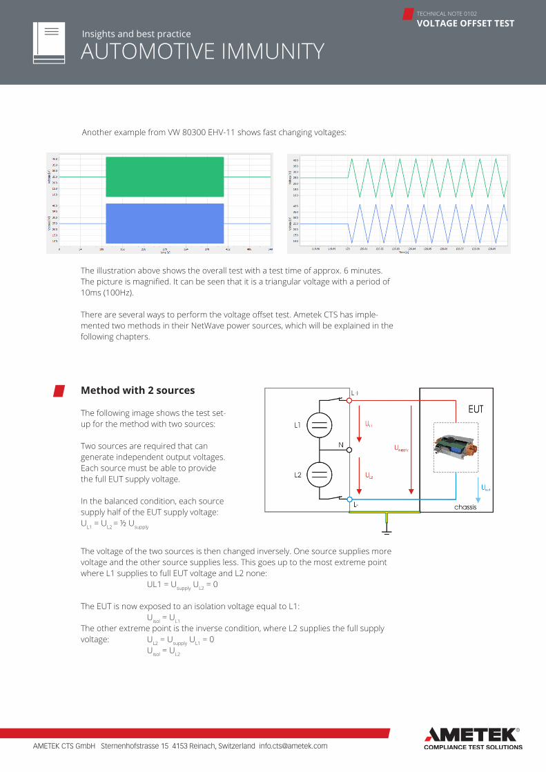
The following image shows the test set-up for the method with two sources:
Two sources are required that can generate independent output voltages. Each source must be able to provide the full EUT supply voltage.
In the balanced condition, each source supply half of the EUT supply voltage:UL1 = UL2 = ½ Usupply
The voltage of the two sources is then changed inversely. One source supplies more voltage and the other source supplies less. This goes up to the most extreme point where L1 supplies to full EUT voltage and L2 none:
UL1 = Usupply UL2 = 0
The EUT is now exposed to an isolation voltage equal to L1: Uisol = UL1
The other extreme point is the inverse condition, where L2 supplies the full supply voltage: UL2 = Usupply UL1 = 0 Uisol = UL2
AMETEK CTS GmbH Sternenhofstrasse 15 4153 Reinach, Switzerland [email protected]
AUTOMOTIVE IMMUNITY
TECHNICAL NOTE 0102
VOLTAGE OFFSET TESTInsights and best practice
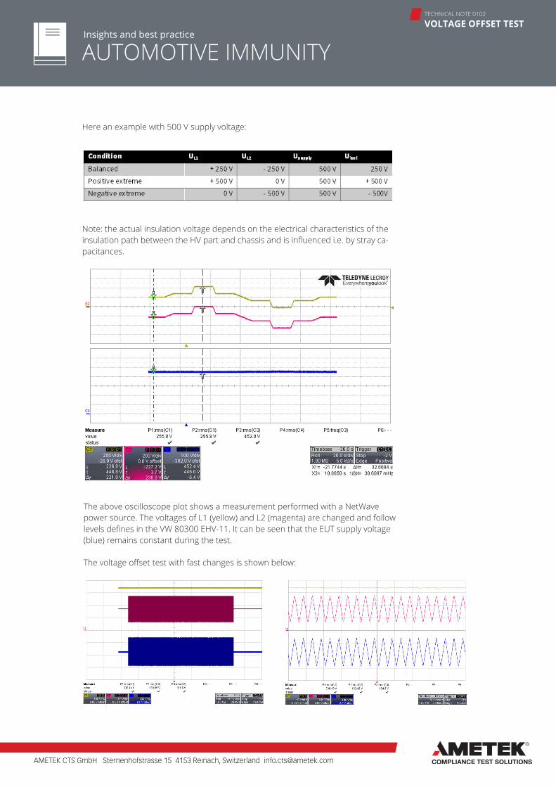
Here an example with 500 V supply voltage:
Note: the actual insulation voltage depends on the electrical characteristics of the insulation path between the HV part and chassis and is influenced i.e. by stray ca-pacitances.
The above oscilloscope plot shows a measurement performed with a NetWave power source. The voltages of L1 (yellow) and L2 (magenta) are changed and follow levels defines in the VW 80300 EHV-11. It can be seen that the EUT supply voltage (blue) remains constant during the test. The voltage offset test with fast changes is shown below:
AMETEK CTS GmbH Sternenhofstrasse 15 4153 Reinach, Switzerland [email protected]
AUTOMOTIVE IMMUNITY
TECHNICAL NOTE 0102
VOLTAGE OFFSET TESTInsights and best practice
The zoomed in plot shows the triangle voltage variations with a period of 10ms. Note the yellow line (EUT supply voltage) which is stable and flat. This is achieved by pre-cisely synchronized voltage supplies with negligible phase shift and minimal voltage unbalance.
There are two limiting factors for this method:a) each of the two sources must be able to generate the full EUT supply voltage. This is usually easily possible up to 500 V. For higher voltage levels i.e. 800 V (Porsche) the sources get expensive.b) To perform the tests, the output of the power sources must be floating. At the most extreme test points, the power source isolation is subjected to the full EUT supply voltage. Therefore, the isolation voltage of the source must be high enough to support this, which is not the case for all sources.
Ametek CTS power sources of the series NetWave .2 and NetWave .3 have this meth-od implemented. The voltage for the voltage offset test is limited to 560 VDC (EUT supply voltage).
Method with 3 phase source
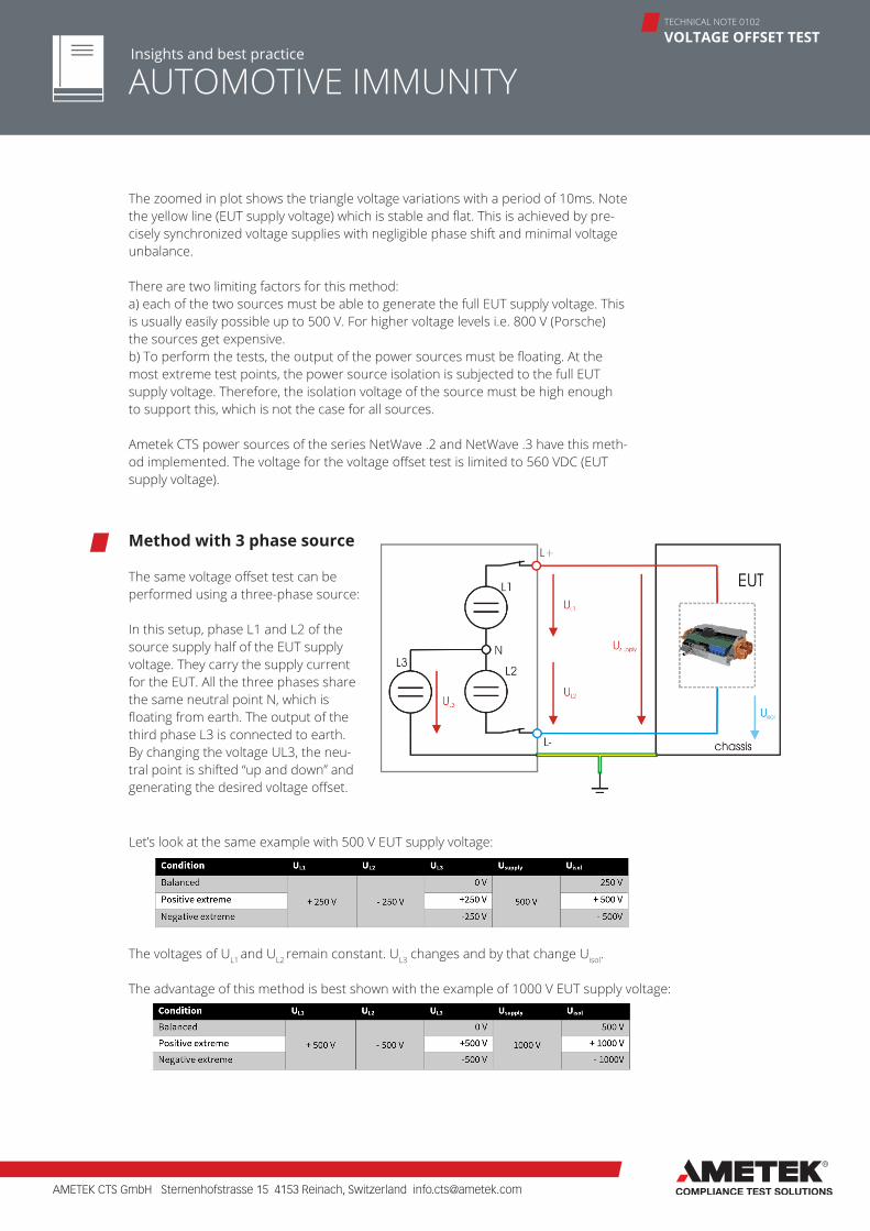
The same voltage offset test can be performed using a three-phase source:
In this setup, phase L1 and L2 of the source supply half of the EUT supply voltage. They carry the supply current for the EUT. All the three phases share the same neutral point N, which is floating from earth. The output of the third phase L3 is connected to earth. By changing the voltage UL3, the neu-tral point is shifted “up and down” and generating the desired voltage offset.
Let’s look at the same example with 500 V EUT supply voltage:
The voltages of UL1 and UL2 remain constant. UL3 changes and by that change Uisol.
The advantage of this method is best shown with the example of 1000 V EUT supply voltage:
AMETEK CTS GmbH Sternenhofstrasse 15 4153 Reinach, Switzerland [email protected]
AUTOMOTIVE IMMUNITY
TECHNICAL NOTE 0102
VOLTAGE OFFSET TESTInsights and best practice
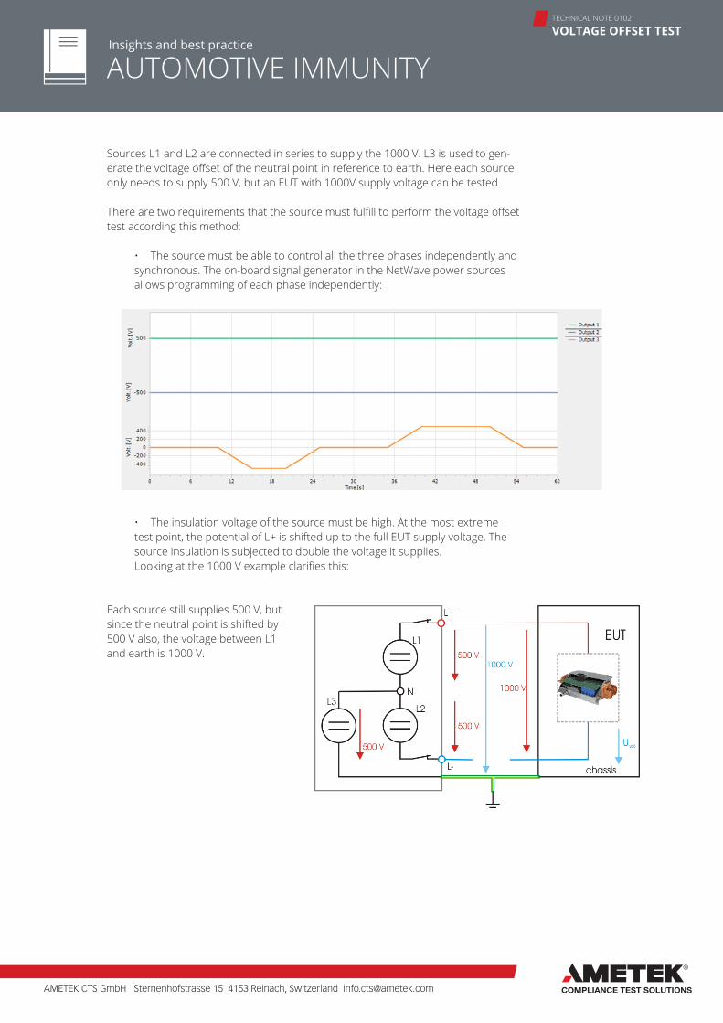
Sources L1 and L2 are connected in series to supply the 1000 V. L3 is used to gen-erate the voltage offset of the neutral point in reference to earth. Here each source only needs to supply 500 V, but an EUT with 1000V supply voltage can be tested.
There are two requirements that the source must fulfill to perform the voltage offset test according this method:
• The source must be able to control all the three phases independently and synchronous. The on-board signal generator in the NetWave power sources allows programming of each phase independently:
• The insulation voltage of the source must be high. At the most extreme test point, the potential of L+ is shifted up to the full EUT supply voltage. The source insulation is subjected to double the voltage it supplies.Looking at the 1000 V example clarifies this:
Each source still supplies 500 V, but since the neutral point is shifted by 500 V also, the voltage between L1 and earth is 1000 V.
AMETEK CTS GmbH Sternenhofstrasse 15 4153 Reinach, Switzerland [email protected]
AUTOMOTIVE IMMUNITY
TECHNICAL NOTE 0102
VOLTAGE OFFSET TESTInsights and best practice
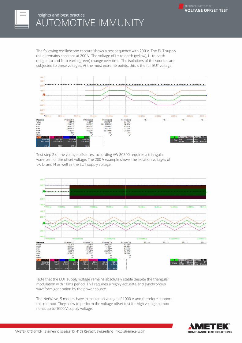
Test step 2 of the voltage offset test according VW 80300 requires a triangular waveform of the offset voltage. The 200 V example shows the isolation voltages of L+, L- and N as well as the EUT supply voltage:
Note that the EUT supply voltage remains absolutely stable despite the triangular modulation with 10ms period. This requires a highly accurate and synchronous waveform generation by the power source.
The NetWave .5 models have in insulation voltage of 1000 V and therefore support this method. They allow to perform the voltage offset test for high voltage compo-nents up to 1000 V supply voltage.
The following oscilloscope capture shows a test sequence with 200 V. The EUT supply (blue) remains constant at 200 V. The voltage of L+ to earth (yellow), L- to earth (magenta) and N to earth (green) change over time. The isolations of the sources are subjected to these voltages. At the most extreme points, this is the full EUT voltage.
AMETEK CTS GmbH Sternenhofstrasse 15 4153 Reinach, Switzerland [email protected]
AUTOMOTIVE IMMUNITY Insights and best practice
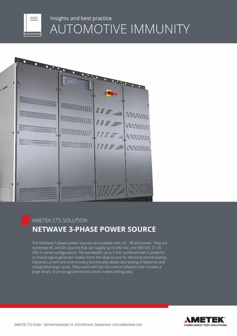
The NetWave 3-phase power sources are available with 20 – 90 kVA power. They are combined AC and DC sources that can supply up to 690 VAC and 560 VDC (1120 VDC in series configuration). The bandwidth up to 5 kHz combined with a powerful on-board signal generator makes them the ideal source for electrical vehicle testing. Optional current sink and recovery functionality allows also testing of batteries and charge/discharge cycles. They come with the net.control software that includes a large library of pre-programmed test which makes testing easy
AMETEK CTS SOLUTION
NETWAVE 3-PHASE POWER SOURCE