inside cisco ios software architecture -...
TRANSCRIPT


ii
Inside Cisco IOS Software ArchitectureVijay Bollapragada, Curtis Murphy, & Russ White
Copyright© 2000 Cisco Systems, Inc.
Cisco Press logo is a trademark of Cisco Systems, Inc.
Published by:Cisco Press800 East 96th StreetIndianapolis, IN 46240 USA
All rights reserved. No part of this book may be reproduced or transmitted in any form or by any means, electronic or mechanical, including photocopying, recording, or by any information storage and retrieval system, without written permission from the publisher, except for the inclusion of brief quotations in a review.
Printed in the United States of America 4 5 6 7 8 9 0
Fourth Printing May 2009
Library of Congress Cataloging-in-Publication Number: 99-64092
ISBN: 1-58705-816-2
Warning and DisclaimerThis book is designed to provide information about Cisco’s proprietary Internetwork Operating System (IOS) software architecture. Every effort has been made to make this book as complete and as accurate as possible, but no warranty or fitness is implied.
The information is provided on an “as is” basis. The author, Cisco Press, and Cisco Systems, Inc., shall have neither liability nor responsibility to any person or entity with respect to any loss or damages arising from the information contained in this book or from the use of the discs or programs that may accompany it.
The opinions expressed in this book belong to the author and are not necessarily those of Cisco Systems, Inc.
Trademark AcknowledgmentsAll terms mentioned in this book that are known to be trademarks or service marks have been appropriately capitalized. Cisco Press or Cisco Systems, Inc. cannot attest to the accuracy of this information. Use of a term in this book should not be regarded as affecting the validity of any trademark or service mark.
Feedback InformationAt Cisco Press, our goal is to create in-depth technical books of the highest quality and value. Each book is crafted with care and precision, undergoing rigorous development that involves the unique expertise of members from the professional technical community.
Readers’ feedback is a natural continuation of this process. If you have any comments regarding how we could improve the quality of this book, or otherwise alter it to better suit your needs, you can contact us through e-mail at [email protected]. Please make sure to include the book title and ISBN in your message.
We greatly appreciate your assistance.

iii
Publisher John WaitEditor-In-Chief John KaneCisco Systems Program Manager Jim LeValleyManaging Editor Patrick KanouseSenior Acquisitions Editor Brett BartowDevelopment Editor Christopher ClevelandProject Editor Jennifer NucklesCopy Editor Theresa WehrleTechnical Editors Mike Brown, Jennifer DeHaven Carroll,
Ron Long, Alexander MarholdTeam Coordinator Amy LewisBook Designer Gina RexrodeCover Designer Louisa AdairProduction Team ArgosyIndexer Kevin Fulcher
Cisco has more than 200 offices worldwide. Addresses, phone numbers, and fax numbers are listed on the Cisco Website at www.cisco.com/go/offices.
CCDE, CCENT, Cisco Eos, Cisco Lumin, Cisco Nexus, Cisco StadiumVision, the Cisco logo, DCE, and Welcome to the Human Network are trademarks.; Changing the Way We Work, Live, Play, and Learn is a service mark; and
Access Registrar, Aironet, AsyncOS, Bringing the Meeting To You, Catalyst, CCDA, CCDP, CCIE, CCIP, CCNA, CCNP, CCSP, CCVP, Cisco, the Cisco Certified Internetwork Expert logo, Cisco IOS, Cisco Press, Cisco Systems,
Cisco Systems Capital, the Cisco Systems logo, Cisco Unity, Collaboration Without Limitation, EtherFast, EtherSwitch, Event Center, Fast Step, Follow Me Browsing, FormShare, GigaDrive, HomeLink, Internet Quotient, IOS,
iPhone, iQ Expertise, the iQ logo, iQ Net Readiness Scorecard, iQuick Study, IronPort, the IronPort logo, LightStream, Linksys, MediaTone, MeetingPlace, MGX, Networkers, Networking Academy, Network Registrar, PCNow,
PIX, PowerPanels, ProConnect, ScriptShare, SenderBase, SMARTnet, Spectrum Expert, StackWise, The Fastest Way to Increase Your Internet Quotient, TransPath, WebEx, and the WebEx logo are registered trademarks of
Cisco Systems, Inc. and/or its affiliates in the United States and certain other countries.
All other trademarks mentioned in this document or Website are the property of their respective owners. The use of the word partner does not imply a partnership relationship between Cisco and any other company. (0805R)
Americas Headquarters Cisco Systems, Inc.
San Jose, CA
Asia Pacific Headquarters Cisco Systems (USA) Pte. Ltd.
Singapore
Europe Headquarters Cisco Systems International BV
Amsterdam, The Netherlands
xii
IntroductionVenture into any bookstore today and you can find numerous books on internetworking covering a wide range of topics from protocols to network design techniques. There’s no question that internetworking has become a popular field with the enormous growth of the Internet and the increasing convergence of voice, video, and data. Cisco has built a very successful business selling the equipment that forms the network infrastructure—by some accounts, Cisco has more than 85 percent of the market—and at the same time has seen its Cisco IOS Software become a de facto industry standard. Yet, although plenty of material is written about network design and the protocols IOS supports, very little information is available from sources other than Cisco.
This lack of information is understandable—IOS is proprietary, after all—but it nevertheless leaves network implementers at a disadvantage. During our experience helping design and troubleshoot IOS-based net-works, we’ve seen many cases where limited IOS architectural knowledge either contributed to a problem or made it more difficult to solve. In addition, we collectively have answered countless numbers of questions (and dispelled some myths) from bewildered Cisco customers about the workings of various IOS features.
This book is an attempt to bring together, in one place, the wealth of information about the architecture and the operation of IOS. Some of this information has been made public previously through forums, Cisco pre-sentations, and the Cisco Technical Assistance Center. Most of the information you cannot find in the Cisco IOS documentation.
ObjectivesInside Cisco IOS Software Architecture is intended to be an IOS “shop manual” for network designers, implementers, and administrators. The objective of this book is to describe key parts of the architecture and the operation of the IOS software. This book also covers the architecture of some of Cisco’s hardware plat-forms. Because IOS is a specialized embedded operating system tightly coupled to the underlying hardware, it’s difficult to describe the software without also considering the hardware architecture. Note, however, that this book is not meant to be an exhaustive manual for Cisco hardware. The hardware descriptions are pro-vided only to help illustrate unique features in the IOS software. You might notice that this book does not cover many of the Cisco platforms; in particular, this book does not cover any of the Catalyst switch prod-ucts, and it omits many of the access routers. In most cases, the missing platforms either are similar to ones that are covered or, in the case of the Catalyst switches, would be best treated in a separate text of their own.

xiii
OrganizationThe book is divided into three general sections. The first covers the general architecture of IOS, including its software infrastructure and packet switching architecture. The second section, beginning with Chapter 3, examines the IOS implementations on a few selected Cisco hardware platforms, covering the design and operation of the platform-specific features. Finally, Chapter 8 describes how IOS implements select Quality of Service (QoS) mechanisms. The book is organized into the following chapters:
• Chapter 1, “Fundamental IOS Software Architecture”—Provides an introduction to operating system concepts and then covers the IOS software infrastructure, including processes, memory management, CPU scheduling, packet buffers, and device drivers.
• Chapter 2, “Packet Switching Architecture”—Gives an overview of the switching architecture and describes the theory of operation of several platform-independent switching methods, includ-ing process switching, fast switching, optimum switching, and Cisco Express Forwarding.
• Chapter 3, “Shared Memory Routers”—Shows how the features discussed in Chapter 1 and Chapter 2 actually are implemented on a platform using the relatively simple shared memory rout-ers as an example.
• Chapter 4, “Early Cbus Routers”—Covers platform-specific switching features in the IOS implementation for the early Cbus routers. Describes the architecture of the AGS+ and Cisco 7000 routers.
• Chapter 5, “Particle-Based Systems”—Describes the particle-based packet buffering scheme using the Cisco 7200 router IOS implementation example. Covers the packet switching implemen-tation on the Cisco 7200.
• Chapter 6, “Cisco 7500 Routers”—Continues the description of the Cbus architecture focusing on the Cisco 7500 router IOS implementation. Also examines the IOS distributed switching imple-mentation on the Versatile Interface Processor (VIP).
• Chapter 7, “The Cisco Gigabit Switch Router: 12000”—Covers the IOS implementation on the Cisco 12000 series routers.
• Chapter 8, “Quality of Service”—Gives an overview of IOS Quality of Service (QoS) and describes several QoS methods, including priority queuing, custom queuing, weighted fair queu-ing, and modified deficit round robin.
• Appendix A, “NetFlow Switching”—Covers the NetFlow feature in IOS used for traffic monitor-ing and billing.

This chapter covers the following key topics:
• Hardware Architecture for Shared Memory Routers
• Packet Buffers for Shared Memory Routers
• Packet Switching on a Shared Memory Router

C H A P T E R 3
Shared Memory RoutersIn the previous two chapters, we covered IOS’ basic architecture and switching methods in the abstract. To understand how IOS actually works, though, it’s helpful to see how it operates on a real router. Because IOS is so closely coupled to the hardware on which it runs, each implementation has its own platform-specific features.
This chapter examines a very basic IOS implementation—the one for a group of routers known collectively as shared memory routers. Shared memory routers consist of several products, including the Cisco 1600, 2500, 4000, 4500, and 4700 series of routers. Although individually they all have their own unique features, together they have two major things in common: they all have a bare-bones architecture (just a CPU, main memory, and interfaces) and they all use the system buffers for packet buffering.
Hardware Architecture for Shared Memory RoutersLet’s examine the hardware architecture on these shared memory platforms in some detail. We start with an overview of the generic shared memory architecture in Figure 3-1, and then mention some of the unique hardware features of platforms within this group.
You can see the overall architecture is fairly basic, consisting of just three major components: the processor (CPU), memory (DRAM), and interface controllers, with the processor and the interface controllers connected to the memory via data busses. Figure 3-1 also shows memory is divided into logical regions, which we’ll examine later.

70 Chapter 3: Shared Memory Routers
Figure 3-1 Shared Memory Router Architecture
CPUThe processor in a shared memory router is truly the brains behind the entire show; it runs IOS and switches packets. The processor is responsible for executing all the switching methods supported on these platforms; there are no offload processors involved.
The type of processor used depends on the platform. For example, the Cisco 1600 and 2500 series use a Motorola 68000 series CPU while the 4500 and 4700 series use a MIPS RISC CPU. You can determine the specific type of processor by looking at the output of the show
TX ring RX ring TX ring RX ring
System buffers
Iomem
Main
Memory (DRAM)
CPU
Interface Interface

Hardware Architecture for Shared Memory Routers 71
version command. Example 3-1 shows the show version output from a Cisco 1600 router. Example 3-2 shows the show version output from a Cisco 4500 router.
MemoryShared memory platforms use dynamic random access memory (DRAM) to hold most of the data in the router. DRAM contains all the routing tables, the caches, the IOS data, the packet buffers, and, on many systems, the IOS code itself.
IOS divides the available DRAM into two logical memory classes: Local and Iomem (I/O memory). In most cases, Local memory is placed into the main region and I/O memory is placed into the iomem region, as illustrated by the show region command output in Example 3-3.
Example 3-1 show version Output from a Cisco 1600 Router
router-1600>show versionCisco Internetwork Operating System Software....cisco 1604 (68360) processor (revision C) with 17920K/512K bytes of memory.Processor board ID 05385389, with hardware revision 00972006....
Example 3-2 show version Output from a Cisco 4500 Router
router-4500#show versionCisco Internetwork Operating System Software ....cisco 4500 (R4K) processor (revision B) with 16384K/16384K bytes of memory.Processor board ID 01657190R4600 processor, Implementation 32, Revision 2.0....
Example 3-3 DRAM Memory Regions Revealed in show region Command Output
Router-4500#show regionRegion Manager:
Start End Size(b) Class Media Name 0x30000000 0x30FFFFFF 16777216 Flash R/O flash 0x38000000 0x383FFFFF 4194304 Flash R/O bootflash 0x40000000 0x40FFFFFF 16777216 Iomem R/W iomem 0x60000000 0x61FFFFFF 33554432 Local R/W main 0x600088A0 0x607229BF 7446816 IText R/O main:text 0x60726000 0x6096506F 2355312 IData R/W main:data 0x60965070 0x609DB1CF 483680 IBss R/W main:bss 0x609DB1D0 0x61FFFFFF 23219760 Local R/W main:mainheap 0x80000000 0x81FFFFFF 33554432 Local R/W main:(main_k0) 0x88000000 0x88FFFFFF 16777216 Iomem R/W iomem:(iomem_k0) 0xA0000000 0xA1FFFFFF 33554432 Local R/W main:(main_k1) 0xA8000000 0xA8FFFFFF 16777216 Iomem R/W iomem:(iomem_k1)

72 Chapter 3: Shared Memory Routers
The sizes of these two regions also are reflected in the output of show version, as illustrated in Example 3-4.
The number before the slash is the amount of Local memory present (32,768 Kb), and the number after the slash is the amount of I/O memory present (16,384 Kb). The total DRAM memory present is the sum of these two numbers (49,152 Kb). For the system in Example 3-3 and Example 3-4, the 32,768 Kb of Local memory is assigned to the region named main and the 16,384 Kb of I/O memory is assigned to the region named iomem.
On shared memory platforms, the main region is used for storing routing tables, caches, general IOS data structures, and often the IOS runtime code—but not for storing packet buffers. Packet buffers are stored in the iomem region, which often is called shared memorybecause it’s shared between the processor and the media interfaces.
On many systems, the DRAM used for Local memory is physically separate from the DRAM used for I/O memory—usually two different banks. On those systems, IOS simply assigns all the available memory in a bank to the appropriate memory regions, one bank for iomem and one bank for main. For the Cisco 1600 and 2500, however, I/O memory and Local memory are both allocated from the same DRAM bank. The amount of I/O memory carved from the installed DRAM depends on the total memory installed:
• 1MB—512 Kb of memory is used for I/O
• 2MB—1 MB of memory is used for I/O
• 4MB and above—2 MB of memory is used for I/O
Location of IOS Runtime Code on Shared Memory SystemsSome IOS shared memory platforms—in particular, the 1600 series and the 2500 series routers—can run IOS directly from Flash memory. If a system is running IOS from Flash, it doesn’t use the main memory region for the IOS runtime code. Instead, it stores the runtime code in a region named flash, as demonstrated in Example 3-5.
Example 3-4 show version Command Output Also Reveals Memory Region Sizes
Cisco Internetwork Operating System SoftwareIOS (tm) 4500 Software (C4500-J-M), Version 11.1(24), RELEASE SOFTWARE (fc1)....cisco 4500 (R4K) processor (revision E) with 32768K/16384K bytes of memory.Processor board ID 09337282....

Hardware Architecture for Shared Memory Routers 73
In Chapter 1, “Fundamental IOS Software Architecture,” you saw that the IText class is where the IOS runtime code is stored. In Example 3-5, the IText memory is assigned to a subregion of flash called flash:text, indicating the system is running IOS from Flash.
You also can determine whether a router is running IOS from Flash or Local memory by checking the image’s filename. The last one or two letters of the filename indicate whether the image is relocatable or run-from-DRAM. The run-from-DRAM images run in Local memory, while the relocatable images run from Flash memory.
The show version output in Example 3-6 is taken from a Cisco 2500, which runs IOS from Flash.
The last letter in the image name (L) means this image is relocatable, and therefore is running from Flash. On the other hand, if the image runs from Local memory (DRAM), the image name ends in either M or MZ, as you can see in the output of show version inExample 3-7.
Example 3-5 show region Output for a Run-from-Flash System
Router-2500#show regionRegion Manager:
Start End Size(b) Class Media Name 0x00000000 0x007FFFFF 8388608 Local R/W main 0x00001000 0x0001922F 98864 IData R/W main:data 0x00019230 0x000666B3 316548 IBss R/W main:bss 0x000666B4 0x007FEFFF 7965004 Local R/W main:heap 0x007FF000 0x007FFFFF 4096 Local R/W main:flhlog 0x00800000 0x009FFFFF 2097152 Iomem R/W iomem 0x03000000 0x03FFFFFF 16777216 Flash R/O flash 0x0304033C 0x037A7D37 7764476 IText R/O flash:text
Example 3-6 Flash-based IOS Image
router-2500>show versionCisco Internetwork Operating System Software IOS (tm) 2500 Software (C2500-JS-L), Version 12.0(7.3)T, MAINTENANCE INTERIM SECopyright (c) 1986-1999 by cisco Systems, Inc.....
Example 3-7 DRAM-based IOS Image
Router-4500>show versionCisco Internetwork Operating System Software IOS (tm) 4500 Software (C4500-P-M), Version 11.2(18)P, RELEASE SOFTWARE (fc1) Copyright (c) 1986-1999 by cisco Systems, Inc. ....

74 Chapter 3: Shared Memory Routers
Memory PoolsIOS creates two memory pools to manage allocation and de-allocation of memory within the DRAM regions. These two pools are named Processor and I/O, as demonstrated in the show memory output in Example 3-8.
The Processor memory pool is created from memory in the main:heap subregion of Local memory and the I/O pool is created from memory in the iomem region of I/O memory. The size of the I/O pool (the number in the Total column in Example 3-8) correlates closely to the size of iomem. However, the size of the Processor pool is always less than the size of the main memory region. The Processor pool gets only a subset of the memory in the mainregion because the remainder must be reserved for the IOS data, the BSS segments, and, on many platforms, the IOS runtime image itself.
NOTE Have you ever wondered why this collection of routers is called shared memory routers? All routers discussed in this book have shared memory, so why are these particular routers singled out? What’s unique about these systems is not that they have shared memory, but that they have only one region of shared memory (I/O memory) and it’s shared between a single main processor and all the interface controllers. In addition, that same memory is used for all packet switching—there’s no data copied between regions to pass a packet from fast to process switching like there is on other platforms.
Interface ControllersInterface controllers are responsible for transferring packets to and from the physical media. They have their own processors, called media controllers, but do not perform any switching or IOS processing operations. Interface controllers perform media control operations and move packets between I/O memory and the network media. Depending on the platform, interface controllers can be implemented as removable port modules or as components on the main system board.
Example 3-8 show memory Output Reveals Memory Pools
router-2500#show memory Head Total(b) Used(b) Free(b) Lowest(b) Largest(b)Processor 3BB08 16528632 878596 15650036 15564280 15630436 I/O 4000000 2097152 473468 1623684 1603060 1623232

Packet Buffers for Shared Memory Routers 75
Packet Buffers for Shared Memory RoutersYou might recall from Chapter 1 that IOS maintains a set of packet buffers called systembuffers that are used primarily for process switching packets. IOS on shared memory routers also uses system buffers, but in a distinct way—it uses the system buffers for allpacket switching, not just process switching.
In addition to the standard public buffer pools, IOS on shared memory platforms also creates some private system buffer pools and special buffer structures for the interface controllers called rings.
Private Buffer PoolsPrivate buffer pools are used for packet switching just like the public pools, but are intended to prevent interface buffer starvation. All interfaces must compete for buffers from the public pools, increasing the probability for buffer contention (which degrades performance) and raising the possibility that a single interface can starve out others needing buffers from a single pool. With the addition of private pools, each interface is given a number of buffers dedicated for its use, so contention is minimized. Although most interfaces receive their own private pool of buffers, some lower speed interfaces, such as asynchronous interfaces, do not.
Unlike the dynamic public pools, the private pools are static and are allocated with a fixed number of buffers at IOS initialization. New buffers cannot be created on demand for these pools. If a buffer is needed and one is not available in the private pool, IOS falls back to the public buffer pool for the size that matches the interface’s MTU.
The output of the show buffers command in Example 3-9 shows both the public and the private pools.
Example 3-9 show buffers Command Output
Router#show buffersBuffer elements: 500 in free list (500 max allowed) 57288024 hits, 0 misses, 0 created
Public buffer pools:Small buffers, 104 bytes (total 50, permanent 50): 50 in free list (20 min, 150 max allowed) 11256002 hits, 0 misses, 0 trims, 0 created 0 failures (0 no memory)Middle buffers, 600 bytes (total 25, permanent 25): 24 in free list (10 min, 150 max allowed) 3660412 hits, 12 misses, 36 trims, 36 created 0 failures (0 no memory)
continues

76 Chapter 3: Shared Memory Routers
Although most of these fields are explained in Chapter 1, some are unique to the interface buffer pools:
• fallbacks—The number of times the interface processor had to fall back to the public buffer pools to find a buffer in which to store a packet.
• max cache size—Some number of buffers in each private buffer pool are cached for faster access; this is the maximum number of buffers that can be cached.
• in cache—The number of cached private buffers.
Notice the private pools do not have a creates or a trims field; this is because these pools are static pools.
Big buffers, 1524 bytes (total 50, permanent 50): 50 in free list (5 min, 150 max allowed) 585512 hits, 14 misses, 12 trims, 12 created 2 failures (0 no memory)VeryBig buffers, 4520 bytes (total 10, permanent 10): 10 in free list (0 min, 100 max allowed) 0 hits, 0 misses, 0 trims, 0 created 0 failures (0 no memory)Large buffers, 5024 bytes (total 0, permanent 0): 0 in free list (0 min, 10 max allowed) 0 hits, 0 misses, 0 trims, 0 created 0 failures (0 no memory)Huge buffers, 18024 bytes (total 0, permanent 0): 0 in free list (0 min, 4 max allowed) 0 hits, 0 misses, 0 trims, 0 created 0 failures (0 no memory)Interface buffer pools:Ethernet0 buffers, 1524 bytes (total 32, permanent 32): 8 in free list (0 min, 32 max allowed) 3398 hits, 3164 fallbacks 8 max cache size, 7 in cacheSerial0 buffers, 1524 bytes (total 32, permanent 32): 7 in free list (0 min, 32 max allowed) 25 hits, 0 fallbacks 8 max cache size, 8 in cacheSerial1 buffers, 1524 bytes (total 32, permanent 32): 7 in free list (0 min, 32 max allowed) 25 hits, 0 fallbacks 8 max cache size, 8 in cache
Example 3-9 show buffers Command Output (Continued)
Packet Buffers for Shared Memory Routers 77
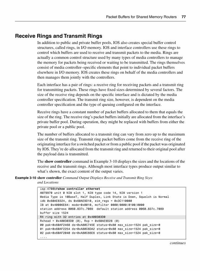
Receive Rings and Transmit RingsIn addition to public and private buffer pools, IOS also creates special buffer control structures, called rings, in I/O memory. IOS and interface controllers use these rings to control which buffers are used to receive and transmit packets to the media. Rings are actually a common control structure used by many types of media controllers to manage the memory for packets being received or waiting to be transmitted. The rings themselves consist of media controller–specific elements that point to individual packet buffers elsewhere in I/O memory. IOS creates these rings on behalf of the media controllers and then manages them jointly with the controllers.
Each interface has a pair of rings: a receive ring for receiving packets and a transmit ring for transmitting packets. These rings have fixed sizes determined by several factors. The size of the receive ring depends on the specific interface and is dictated by the media controller specification. The transmit ring size, however, is dependent on the media controller specification and the type of queuing configured on the interface.
Receive rings have a constant number of packet buffers allocated to them that equals the size of the ring. The receive ring’s packet buffers initially are allocated from the interface’s private buffer pool. During operation, they might be replaced with buffers from either the private pool or a public pool.
The number of buffers allocated to a transmit ring can vary from zero up to the maximum size of the transmit ring. Transmit ring packet buffers come from the receive ring of the originating interface for a switched packet or from a public pool if the packet was originated by IOS. They’re de-allocated from the transmit ring and returned to their original pool after the payload data is transmitted.
The show controller command in Example 3-10 displays the sizes and the locations of the receive and the transmit rings. Although most interface types produce output similar to what’s shown, the exact content of the output varies.
Example 3-10 show controller Command Output Displays Receive and Transmit Ring Sizes and Locations
isp-4700b#show controller ethernetAM79970 unit 0 NIM slot 1, NIM type code 14, NIM version 1Media Type is 10BaseT, Half Duplex, Link State is Down, Squelch is Normalidb 0x60AE8324, ds 0x60AE9D10, eim_regs = 0x3C110000IB at 0x40006E64: mode=0x0010, mcfilter 0000/0000/0100/0000station address 0060.837c.7089 default station address 0060.837c.7089buffer size 1524RX ring with 32 entries at 0x400303D0Rxhead = 0x400303D0 (0), Rxp = 0x60AE9D28 (0)00 pak=0x60AF2468 ds=0xA80C745E status=0x80 max_size=1524 pak_size=001 pak=0x60AF2254 ds=0xA80C6DA2 status=0x80 max_size=1524 pak_size=002 pak=0x60AF2040 ds=0xA80C66E6 status=0x80 max_size=1524 pak_size=0....
continues
78 Chapter 3: Shared Memory Routers
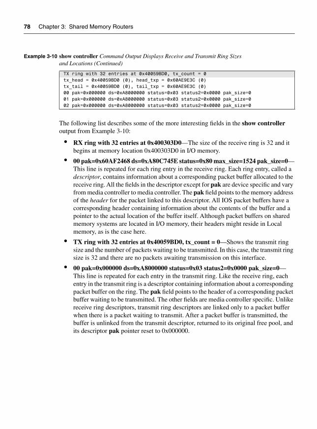
The following list describes some of the more interesting fields in the show controlleroutput from Example 3-10:
• RX ring with 32 entries at 0x400303D0—The size of the receive ring is 32 and it begins at memory location 0x400303D0 in I/O memory.
• 00 pak=0x60AF2468 ds=0xA80C745E status=0x80 max_size=1524 pak_size=0—This line is repeated for each ring entry in the receive ring. Each ring entry, called a descriptor, contains information about a corresponding packet buffer allocated to the receive ring. All the fields in the descriptor except for pak are device specific and vary from media controller to media controller. The pak field points to the memory address of the header for the packet linked to this descriptor. All IOS packet buffers have a corresponding header containing information about the contents of the buffer and a pointer to the actual location of the buffer itself. Although packet buffers on shared memory systems are located in I/O memory, their headers might reside in Local memory, as is the case here.
• TX ring with 32 entries at 0x40059BD0, tx_count = 0—Shows the transmit ring size and the number of packets waiting to be transmitted. In this case, the transmit ring size is 32 and there are no packets awaiting transmission on this interface.
• 00 pak=0x000000 ds=0xA8000000 status=0x03 status2=0x0000 pak_size=0—This line is repeated for each entry in the transmit ring. Like the receive ring, each entry in the transmit ring is a descriptor containing information about a corresponding packet buffer on the ring. The pak field points to the header of a corresponding packet buffer waiting to be transmitted. The other fields are media controller specific. Unlike receive ring descriptors, transmit ring descriptors are linked only to a packet buffer when there is a packet waiting to transmit. After a packet buffer is transmitted, the buffer is unlinked from the transmit descriptor, returned to its original free pool, and its descriptor pak pointer reset to 0x000000.
TX ring with 32 entries at 0x40059BD0, tx_count = 0tx_head = 0x40059BD0 (0), head_txp = 0x60AE9E3C (0)tx_tail = 0x40059BD0 (0), tail_txp = 0x60AE9E3C (0)00 pak=0x000000 ds=0xA8000000 status=0x03 status2=0x0000 pak_size=001 pak=0x000000 ds=0xA8000000 status=0x03 status2=0x0000 pak_size=002 pak=0x000000 ds=0xA8000000 status=0x03 status2=0x0000 pak_size=0
Example 3-10 show controller Command Output Displays Receive and Transmit Ring Sizes and Locations (Continued)

Packet Switching on a Shared Memory Router 79
Packet Switching on a Shared Memory RouterNow that we’ve looked at the general hardware architecture of the shared memory routers and how IOS divides their memory, let’s look at how IOS actually switches packets. IOS on shared memory routers supports the following:
• Process switching
• CEF switching
• Fast switching
There are three stages in IOS packet switching:
1 Receiving the packet
2 Switching the packet
3 Transmitting the packet
Receiving the PacketFigure 3-2 illustrates the steps of the packet receive stage.
Figure 3-2 Receiving the Packet
Processor
Route cache
Public bufferpool
Private bufferpool
InterfaceProcessor
InterfaceProcessor
Input queue Output queue
RX ring TX ring
DMA DMA
3.2
3.11
2

80 Chapter 3: Shared Memory Routers
Step 1 The interface media controller detects a packet on the network media and copies it into a buffer pointed to by the first free element in the receive ring (that is, the next buffer the media controller owns). Media controllers use the DMA (direct memory access) method to copy packet data into memory.
Step 2 The media controller changes ownership of the packet buffer back to the processor and issues a receive interrupt to the processor. The media controller does not have to wait for a response from the CPU and continues to receive incoming packets into other buffers linked to the receive ring.
NOTE Notice in Step 2 the media controller can continue to receive incoming packets into the receive ring. Therefore, it’s possible for the media controller to fill the receive ring before the processor processes all the new buffers in the ring. This condition is called an overrun;when it occurs, all incoming packets are dropped until the processor catches up.
Step 3 The CPU responds to the receive interrupt, and then attempts to remove the newly-filled buffer from the receive ring and replenish the ring from the interface’s private pool. Three outcomes are possible:
3.1 A free buffer is available in the interface’s private pool to replenish the receive ring: The free buffer is linked to the receive ring and packet switching continues with Step 4.
3.2 A free buffer is not available in the interface’s private pool, so the receive ring is replenished by falling back to the global pool that matches the interface’s MTU. The fallbackcounter is incremented for the private pool.
3.3 If a free buffer is not available in the public pool as well, the incoming packet is dropped and the ignore counter is incremented. Further, the interface is throttled, and all incoming traffic is ignored on this interface for some short period of time.

Packet Switching on a Shared Memory Router 81
Switching the PacketStep 4 After the receive ring is replenished, the CPU begins actually switching
the packet. This operation consists of locating information about where to send the packet (next hop) and the MAC header to rewrite onto the packet.
IOS attempts to switch the packet using the fastest method configured on the interface. On shared memory systems, it first tries CEF switching (if configured), then fast switching, and finally falls back to process switching if none of the others work. Figure 3-3 illustrates the steps of the packet switching stage and the list that follows describes the steps illustrated in the figure.
Figure 3-3 Switching the Packet
Processor
Route cache
Public bufferpool
Private bufferpool
Input queue Output queue
RX ring TX ring
4 & 5
6
Ip input7
InterfaceProcessor
InterfaceProcessor
DMA DMA

82 Chapter 3: Shared Memory Routers
Step 5 While still in the receive interrupt context, IOS attempts to use the CEF table (first) or fast switching cache (second) to make a switching decision.
5.1 CEF switching—If CEF switching is enabled on the interface, then CEF switching is attempted. Four different outcomes are possible:
5.1.1 If there are valid CEF and adjacency table entries, IOS rewrites the MAC header on the packet and begins transmitting it in Step 8, the packet transmit stage.
5.1.2 If the CEF adjacency entry for this destination points to a punt adjacency, IOS proceeds to try fast switching (see Step 5.2).
5.1.3 If the CEF table entry for this packet points to a receive adjacency, the packet is queued for process switching.
5.1.4 If there is no CEF entry for the destination, the packet is dropped.
5.2 Fast switching—If CEF is not enabled or the packet cannot be CEF switched, IOS attempts to fast switch the packet.
5.2.1 If there is a valid fast cache entry for this destination, IOS rewrites the MAC header information and begins transmitting the packet (Step 8, packet transmit stage).
5.2.2 If there is no valid fast cache entry, the packet is queued for process switching (Step 6).
Step 6 Process switching—If both CEF switching and fast switching fail, IOS falls back to process switching. The packet is placed in the input queue of the appropriate process (an IP packet is placed in the queue for the IP Input process, for instance), and the receive interrupt is dismissed.
Step 7 Eventually, the packet switching process runs, switching the packet and rewriting the MAC header as needed. Note the packet still has not moved from the buffer it was originally copied into. After the packet is switched, IOS continues to the packet transmit stage, for process switching (Step 9).

Packet Switching on a Shared Memory Router 83
Transmitting the PacketFigure 3-4 illustrates the steps of packet transmit stage.
Figure 3-4 Transmitting the Packet
Step 8 If the packet was CEF switched or fast switched, then while still in receive interrupt context IOS checks to see if there are packets on the output queue of the outbound interface.
8.1 If there are packets already on the output hold queue for the interface, IOS places the packet on the output hold queue instead of directly into the transmit ring to reduce the possibility of out-of-order packets, and then proceeds to Step 8.3.
8.2 If the output hold queue is empty, IOS places the packet on the transmit ring of the output interface by linking the packet buffer to a transmit ring descriptor. The receive interrupt is dismissed and processing continues with Step 11. If there is no room on the transmit ring, the packet is placed on the output hold queue instead and the receive interrupt is dismissed.
Processor
Cache
Public bufferpool
Private bufferpool
Input Q Output Q
RX ring/queue TX ring/queue
11
10
12
8
8.2
InterfaceProcessor
InterfaceProcessor
DMA DMA

84 Chapter 3: Shared Memory Routers
8.3 If the output hold queue is full, the packet is dropped, the output drop counter is incremented, and the receive interrupt is dismissed.
NOTE In Step 8 of the transmit stage, notice that IOS checks the output hold queue first before placing any CEF or fast switched packets on the transmit ring. This reduces the possibility of transmitting packets out of order. How can packets get out of order when they’re being switched as they’re received? Consider the following example.
Let’s assume the first packet in a given conversation (flow) between two hosts arrives at the router. IOS attempts to fast switch the packet and finds there is no fast cache entry. So, the packet is handed off to the IP Input process for process switching.
So far, everything is fine. In the process of switching the packet, IP Input builds a cache entry for this flow of packets and places the first packet on the output queue of the outbound interface.
Now, let’s assume that just at this moment a second packet arrives for the same flow. IOS fast switches the second packet (because the cache entry has now been built) and gets ready to transmit it. If IOS puts this second packet directly on the transmit ring, it is transmitted before the first packet, which is still waiting in the output queue. To prevent this situation from occurring, IOS always makes certain the output queue of the outbound interface is empty before placing any CEF-switched or fast-switched packets directly on the transmit ring.
Step 9 If the packet was process switched, the packet is placed on the output queue for the output interface. If the output queue is full, the packet is dropped and the output drop counter is incremented.
Step 10 IOS attempts to find a free descriptor in the output interface transmit ring. If a free descriptor exists, IOS removes the packet from the output hold queue and links the buffer to the transmit ring. If no free descriptor exists (that is, the ring is full), IOS leaves the packet in the output hold queue until the media controller transmits a packet from the ring and frees a descriptor.
Step 11 The outbound interface media controller polls its transmit ring periodically for packets that need to be transmitted. As soon as the media controller detects a packet, it copies the packet onto the network media and raises a transmit interrupt to the processor.

Summary 85
Step 12 IOS acknowledges the transmit interrupt, unlinks the packet buffer from the transmit ring, and returns the buffer to the pool of buffers from which it originally came. IOS then checks the output hold queue for the interface; if there are any packets waiting in the output hold queue, IOS removes the next one from the queue and links it to the transmit ring. Finally, the transmit interrupt is dismissed.
SummaryThis chapter covered the IOS implementation on Cisco’s shared memory architecture routers, including the 2500 series, of which there are more than 1 million in use today. You saw how IOS divides memory into regions and how it actually switches packets on these platforms.

I N D E X
Symbols* (asterisk)
process switching, 44show process command, 18
2-way radix trees (Fast Cache), 51–52256-way multiway tree (mtree), 56–577000 series routers, 87, 92–937200 series routers, 99–101
hardware, 101–104memory, 104–106packet switching, 106–111
7500 series routers, 113data buses, 114packet switching, 123
receiving packets, 124, 127switching packets, 126–129transmitting packets, 129–131
RSP (Route Switch Processor), 115–123CPUs (central processing units), 116main memory, 123MEMD (memory D), 116–122
troubleshooting, 142CPUs (central processing units), 142–144ignore counters, 145input drop counter, 144output drop counters, 145
VIP (Versatile Interface Processor), 131–140models, 134–135receive side buffering, 141–142
12000 series routers (Gigabit Switch Router), 147hardware, 147
GRP (Gigabit Route Processor), 154–155LCs (Line Cards), 155–161Maintenance Bus (MBUS), 154switching fabric, 148–154
MDRR (Modified Deficit Round Robin), 191–195
packet switching, 161–167
Aactive field (show queueing command), 183adapters
7200 series routers, 99, 104VIP (Versatile Interface Processor), 133
address space, virtual, 9addresses
memory regions, 11–12MMU (memory map unit), 6
adjacency tables, CEF (Cisco Express Forwarding), 60–62
aggregate queue limit field (show interface fair command), 191
aggregation, RBA (Router-Based Flow Aggregation Export), 205
aging cache entries, Fast Cache, 55AGS+ router, 87–89algorithms (MEMD buffer carving), 118–122aliases, memory regions, 11–12alignment errors (Cisco 7500 series routers),
142–143Allocated field (show process memory
command), 29alternate mode, MDRR (Modified Deficit Round
Robin), 192–193arbitration phase (12000 series routers), 148architecture (IOS), 7–8
device drivers, 38kernel, 20
memory manager, 24–31scheduler, 20–24watchdog timers, 23–24
memory, 9memory pools, 12–13regions, 9–12
operating systems, 3packet buffer management, 31
buffer pool manager, 31system buffers, 32–38
processes, 13life cycle stages, 14–16output, 17–19priorities, 16–17

208
shared memory routers, 69–70CPUs (central processing units), 70–71DRAM (dynamic random access
memory), 71–74interface controllers, 74
software infrastructure, 3virtual memory, 7
AS (Autonomous System), 204–205AS field (show ip cache verbose flow command),
204ASICs, Line Cards, 160–161asterisk (*)
process switching, 44show process command, 18
autonomous switching (Cbus), 90Autonomous System aggregation, 205average queue size, 196
Bbackbone routers, 59backing store, 131bad hop counts, 144balancing loads, 44–45bandwidth
12000 series routers switching fabric, 151–152file transfers, 169QoS (Quality of Service), 170–171terminal sessions, 169video, 169voice traffic, 169
bare-bones architecture (shared memory routers), 69blocks, memory
chunk manager, 28memory pool manager, 25–26
BMAs (Buffer Manager ASICs), 160–161broadcast storms, 144
buffers, 8buffer pools
buffer pool manager, 31–32Cisco 7500 series routers, 117–118
contiguous, 95MEMD, 120particle buffering, 95–97
coalescing, 99data blocks, 97headers, 97pools, 98
system buffers, 32–38VIP (Versatile Interface Processor), 141–142
burst memory, 163buses
7200 series routers, 92–93, 99–100, 103–1047500 series routers, 11412000 series routers, 148–149AGS+ routers, 89Cbus, 87
autonomous switching, 90Cisco 7000 Series router, 92–93controller, 88Fast Packet Memory, 91–92
Mutlibus, 87packet switching, 41VIP (Versatile Interface Processor), 133–134
CC character (show process command), 18cache
CEF (Cisco Express Forwarding), 58–59load sharing, 63–64tables, 59, 61–62
Fast Cache, 47–49cache maintenance, 53–55hash buckets, 50–51hash tables, 50–51
architecture (IOS)

209
load sharing, 55–56radix trees, 51–52storing IP prefixes, 52–53
NetFlow, 202–204optimum switching, 56–58
cache misses, 49Cached adjacency (CEF adjacency tables), 62calendar queues (DWFQ), 190CAR (Committed Access Rate), 199Cbus, 87
Cisco 7000 Series router, 92–93controller, 88packet switching, 90
autonomous, 90Fast Packet Memory, 91–92
CBWFQ (Class-Based Weighted Fair Queuing), 184–189
CEF (Cisco Express Forwarding), 58–597200 series routers, 106, 110–111dCEF (distributed Cisco Express Forwarding),
189load sharing, 63–64shared memory routers, 81–82tables, 59, 61–62
cells (12000 series routers), 154Chars In (Cisco 7500 series routers), 143chassis models (7200 series routers), 100Check heaps (show process command), 19chunk manager, 28Cisco Express Forwarding. See CEFCisco IOS. See architectureClass-Based Weighted Fair Queuing. See CBWFQclass command, 185class-default option (class command), 185class-map command, 185CLI (command-line interface)
CBWFQ (Class-Based WFQ), 184–186parsers, 14
Clock Scheduler card (CSC), 150coalescing, particle, 99
commandsclass, 185class-map, 185cos-queue-group, 194fair-queue, 179, 182ip route-cache flow, 202ip routing, 14no ip routing, 14queue-limit, 185random-detect, 185rx-cos-slot, 194service-policy, 185show adjacency, 62show align, 143show buffer, 32–33show buffers, 35–38, 75, 98show controller, 77show controller cbus, 119–122, 145show controller fia, 150show controller frfab queue, 160show controller tofab queue, 158show controller vip accumulator, 141show diag, 134, 157show interface, 144–145show interface random, 197show interface stat, 143–144show ip cache optimum, 58show ip cache verbose, 49–50show ip cache verbose flow, 203–204show ip cef summary, 59show ip route, 45show ip spd, 199show ip traffic, 144show memory, 12–13, 26–27, 31, 74show memory free, 27–28show memory summary, 123show policy interface, 186show policy policy-map, 186show process, 17–19show process cpu, 22–23, 142–143show process memory, 29–30
commands

210
show queueing, 182–183show region, 10, 71show version, 70–72, 115slot-table-cos, 194
Committed Access Rate (CAR), 199configuration commands
ip routing, 14no ip routing, 14
configuring, 173–1757200 series routers, 100MDRR (Modified Deficit Round Robin),
194–195NetFlow, 201RED (random early detection), 197–198WFQ (Weighted Fair Queuing), 182–183
congestion avoidance, 172, 195–198congestion management, 171–172
custom queuing, 175–178LLQ (Low Latency Queuing), 187–188MDRR (Modified Deficit Round Robin),
191–195priority queuing, 172–175Weighted Fair Queuing (WFQ), 178–179
CBWFQ (Class-Based WRQ), 184–187configuring, 182–183DWFQ (Distributed WFQ), 188–191Flow-Based WFQ, 179–182
congestive-discard-threshold (fair-queue command), 182context switches, 5
preemptive multitasking, 5processes, 13
contexts (threads), 4contiguous buffers, 95control store, 88controllers (7200 series routers), 104cos-queue-group command, 194cost, process switching, 44–45counters
load share, 44–45MEMD (memory D), 92output drop, 129show buffer command, 34
CPUs (central processing units)7500 series RSP (Route Switch Processor), 116,
142–144AGS+ routers, 89context switches, 5GRP (Gigabit Route Processor), 154–155interrupts, 7, 14multitasking operating systems, 4–5packet switching
shared memory routers, 80–81preemptive multitasking operating systems, 5–6processes, 22–23shared memory routers, 70–71VIP (Versatile Interface Processor), 133
created field (show buffer command), 34creation stage, 15Critical background (show process command), 19critical priorities, 16crossbar switching fabric (12000 series routers),
149–150CSC (Clock Scheduler card), 150CyBus, VIP (Versatile Interface Processor), 133–134
DD character (show process command), 18data blocks (particle buffering), 97data buses (Cisco 7500 series routers), 114datagrams, exporting flow data, 204Dead queue, 20dead state, 16Dead summary lines (show process memory
command), 30deficit counters, MDRR (Modified Deficit Round
Robin), 193delay
terminal sessions, 169video, 169voice traffic, 169
commands

211
Denial of Service attacks (Cisco 7500 series routers), 144
depth field (show queueing command), 183descriptors, 78Destination Prefix aggregation, RBA (Router-Based
Flow Aggregation Export), 205device drivers, 8, 38discards field
show policy interface command, 187show queueing command, 183
Distributed CBWFQ (DCBWFQ), 184, 189distributed Cisco Express Forwarding (dCEF), 189distributed switching, 135–140Distributed Weighted Fair Queuing (DWFQ),
171, 178DRAM
7200 series routers, 104–106shared memory routers, 71–74
drivers, device, 38drop counters, 84drops field (show queueing command), 183duplicate memory regions (aliases), 11DWFQ (Distributed Weighted Fair Queuing), 171,
178, 188–191dynamic packet buffer pools, 32dynamic-queues (fair-queue command), 182
EE character (show process command), 18EIGRP (Enhanced Interior Gateway Routing
Protocol), 45End addresses (memory regions), 10engine 0 LCs (Line Cards), 160–163engine 1 LCs (Line Cards), 160–163engine 2 LCs (Line Cards), 160–161, 164–165errors (Cisco 7500 series routers), 142–143exceptions (Cisco 7500 series routers), 143EXEC commands
parsers, 14show memory, 26–27
show memory free, 27–28show process, 19show region, 10
execution stage, 16exporting NetFlow data, 204
FFabric Interface ASIC (FIA), 160fair-queue command, 179, 182fallback counter, 80fallbacks field (show buffers command), 76Fast Cache, 47–49
cache maintenance, 53–55hash buckets, 50–51hash tables, 50–51load sharing, 55–56radix trees, 51–52storing IP prefixes, 52–53
fast memory pools (Cisco 7500 series router), 123Fast memory region, 9Fast Packet Memory
AGS+ routers, 89Cbus, 91–92MEMD. See MEMD (memory D)
fast switching, 8. See also Fast Cache7200 series routers, 106, 110–111shared memory routers, 82show process cpu command, 23
fast switching pools (particle buffers), 98FIA (packet switching ASIC), 160fields
show buffer command, 33–34show buffers command, 76show controller cbus command, 119–120show controller command, 78show controller tofab queue command, 159show interface fair command, 190show interface random command, 198show ip cache verbose flow command, 203–204show policy interface command, 187
fields

212
show process command, 18–19show process memory command, 29show queueing command, 183
FIFO (first-in, first-out)limitations, 170–171run-to-completion scheduling, 4–5
file transfers (Quality of Service), 169filenames, runtime memory locations, 73Flash memory, 9, 72–73Flgs field (show ip cache verbose flow
command), 204flow (NetFlow), 201–202
exporting data, 204flow cache, 202–204RBA (Router-Based Flow Aggregation
Export), 205Flow-Based DWFQ (Distributed Weighted Fair
Queuing), 188–189Flow-Based WFQ (Weighted Fair Queuing),
179–182fragmentation, memory, 25, 31free buffers, 80free function, 24Free output (show memory command), 13Freed field (show process memory command), 29FrFab SDRAM, 158full bandwidth mode (12000 series routers), 151functions
free, 24malloc, 24
GGeeks images, 59Generic Traffic Shaping (GTS), 199Getbufs field (show process memory command), 29Glean (CEF adjacency tables), 62global free queue (Cisco 7500 series router), 122global synchronization, 195–196GRP (Gigabit Route Processor), 154–155GSR (Gigabit Switch Router), 147
hardware, 147GRP (Gigabit Route Processor), 154–155LCs (Line Cards), 155–161
Maintenance Bus (MBUS), 154switching fabric, 148–154
MDRR (Modified Deficit Round Robin), 191–195
packet switching, 161–167GTS (Generic Traffic Shaping), 199
HH character (show process command), 18hardware
7200 series routers, 101–10412000 series routers (Gigabit Switch
Router), 147GRP (Gigabit Route Processor), 154–155LCs (Line Cards), 155–161MBUS (Maintenance Bus), 154switching fabric, 148–154
abstraction, 4, 38interrupts, 14shared memory routers, 69–70
CPUs (central processing units), 70–71DRAM (dynamic random access
memory), 71–74interface controllers, 74
hash buckets (Fast Cache), 50–51hash tables (Fast Cache), 50–51Head of Line blocking (HoLB), 152–153headers
MDRR (Modified Deficit Round Robin), 192particle buffering, 97
headroom, 199heap (memory), 6, 12–13hg character (show process command), 18high priorities, 16high queues (priority queuing), 173hits field (show buffer command), 33HoLB (Head of Line blocking), 152–153Holding field (show process memory command), 29hop counts, bad, 144Host-route (CEF adjacency tables), 62hot-swappable interface cards, 92
fields

213
I–JI/O
busses7200 series routers, 104packet switching, 41
controllers, 104memory
Fast Cache, 48process switching, 43–47memory pools, 12–13, 74
packet switching. See packet switchingpools, 104–106
IData memory region, 9IDBs (interface descriptor blocks), 38, 117idle CPU time, 23Idle queue, 20idle state, 16IEss memory region, 9ignore counter
7500 series routers, 145MEMD, 121packet switching, 80
IGRP (Interior Gateway Routing Protocol), 45image filenames, 73in cache field (show buffers command), 76in free list field (show buffer command), 33Incomplete (CEF adjacency tables), 62individual queue limit field (show interface fair
command), 191Init summary lines (show process memory
command), 30input drop counters (Cisco 7500 series routers), 144input hold queue count, 129input keyword, 185interactive voice traffic (Quality of Service), 169interface descriptor blocks (IDBs), 38, 117interfaces
7000 series routers, 92–937500 series router, 117, 123device drivers, 38shared memory routers, 74
Interior Gateway Routing Protocol (IGRP), 45interleaves field (show queueing command), 183
Internet backbone, CEF (Cisco Express Forwarding), 59
interrupts, 14interrupt handlers, 7interrupt throttling, 23process switching, 43processes, 14
invalidating cache entries (Fast Cache), 54Invoked field (show process command), 18Iomem (I/O memory), 71–72Iomem memory region, 9IOS. See architectureIP (Internet Protocol)
headers, 192prefixes, 52–53
ip route-cache flow command, 202ip routing command, 14ip_input process, 14IPC Queue field (show controller tofab queue
command), 159ISP Geeks images, 59IText memory region, 9, 73
KK character (show process command), 18kernel, 8, 20
memory manager, 24–31allocation request failures, 30–31chunk manager, 28memory pool manager, 24–28process utilization, 29–30region manager, 24
parsers, 14preemptive multitasking, 5scheduler, 20–24scheduling threads, 4–5watchdog timers, 23–24
keywordsinput, 185output, 185
keywords

214
LL character (show process command), 18Largest output (show memory command), 13LCs (Line Cards), 155–161
12000 series routers, 148packet forwarding engines, 156–160
leaks, memory, 30–31LLQ (Low Latency Queuing), 187–188load sharing
CEF (Cisco Express Forwarding), 63–64counters, 44–45Fast Cache packet switching, 55–56process switching, 44–45
local free queue (Cisco 7500 series router MEMD), 122
local memory (shared memory routers), 71–72Local memory region, 9, 11Logger (show process command), 19lookups, 47Low Latency Queuing (LLQ), 187–188low priorities, 17low queues, 173Lowest output (show memory command), 13
MM character (show process command), 18MAC (Media Access Control) headers, 43, 46–47main memory
packet forwarding engines, 156–157VIP (Versatile Interface Processor), 133
Maintenance Bus (MBUS), 154malloc function, 24management, resource, 6–7managers
buffer pool manager, 31–32memory manager, 24
allocation request failures, 30–31chunk manager, 28kernel, 24–31
memory pool manager, 24–28process utilization, 29–30region manager, 24
maps, memory, 10–11mark weight field (show interface random
command), 198max active field (show queueing command), 183max allowed field (show buffer command), 33max available buffers field
show interface fair command, 191show interface random command, 198
max buffer data size field (show controller tofab queue command), 159
max cache size field (show buffers command), 76Max Threshold field (show policy interface
command), 187max threshold field (show interface random
command), 198max total field (show queueing command), 183maximum threshold, RED (random early
detection), 196maxrxcurr (Cisco 7500 series routers), 122MBUS (Maintenance Bus), 154MDRR (Modified Deficit Round Robin), 171,
191–195media controllers, 74, 80medium priorities, 17medium queues, 173MEMD (memory D), 91–92
7500 series routers, 118–122buffers, 118–122, 141–142
memory7200 series routers, 104–1067500 series routers, 12312000 series routers, 148–149AGS+ routers, 89allocation request failures, 30–31fragmentation, 25, 31IOS management, 9leaks, 30–31memory pools, 12–13operating systems, 6–7packet forwarding engines, 156–160
L character (show process command)
215
particle data blocks, 97process switching, 43–47regions, 9–12shared memory routers, 69
CPUs (central processing units), 70–71DRAM (dynamic random access
memory), 71–74hardware architecture, 69–70interface controllers, 74packet buffers, 75–78packet switching, 79–85
VIP (Versatile Interface Processor), 133memory manager, 24
allocation request failures, 30–31chunk manager, 28kernel, 24–31memory pool manager, 24–28process utilization, 29–30region manager, 24
memory map, 10–11memory map unit (MMU), 6, 9memory paging, 9memory pools, 12–13
7200 series routers, 1047500 series router, 123DRAM regions, 74particle buffering, 96, 98
metrics (process switching), 44–45Middle buffers, 33midplanes (7200 series routers), 100min field (show buffer command), 33min threshold field (show interface random
command), 198minimum threshold, RED (random early detection),
196misses field (show buffer command), 33misses, cache, 49MMU (memory map unit), 6, 9modification stage, 15Modified Deficit Round Robin (MDRR), 171,
191–195modular command-line interface (CLI), 184–186
monitoring DWFQ (Distributed Weighted Fair Queuing), 190–191
mtree (256-way multiway tree), 56–57mtrie tables, 60–61MTU sizes, 117–118Multibus, 87-89Multiservice Interchange Connections, 100multitasking, 4, 13
non-preemptive, 16preempting threads, 5–6scheduling threads, 5
Nnesting memory regions, 9Net background (show process command), 19NetFlow, 201–202
exporting data, 204flow cache, 202–204RBA (Router-Based Flow Aggregation Export),
205network interfaces (device drivers), 38Network Processing Engine (NPE), 99–101,
103–106new state, 15no buffer drops field (show interface random
command), 198no ip routing command, 14no memory field (show buffer command), 34nobuffer drops field (show interface fair command),
190nodes, NULL, 58non-preemptive multitasking, 16normal pools (particle buffers), 98normal queues, priority queuing, 173NPE (Network Processing Engine), 99–101,
103–106NULL nodes, 58
NULL nodes

216
Ooperating systems, 3
CPUs (central processing units), 7hardware abstraction, 4IOS. See IOSmemory management, 6–7multitasking, 4, 13
non-preemptive, 16preempting threads, 5–6scheduling threads, 5
resource management, 4optimum switching, 56–58output
show buffer command, 32–33show buffers command, 35–38show controller cbus command, 119–122show diag command, 134show ip cache optimum command, 58show ip cache verbose command, 49–50show memory command, 12–13, 26–27show memory free command, 27–28show process command, 17–19show process cpu command, 22show process memory command, 29–30
output drop counter, 1297500 series routers, 145packet switching, 84
output keyword, 185
Ppacket buffering, 8
contiguous buffers, 95headers, 97management, 31–38
particle buffering, 95–97coalescing, 99data blocks, 97headers, 97pools, 98
pools, 31–327500 series routers, 117–118system buffers, 32–38
shared memory routers, 75private buffer pools, 75–76rings, 77–78
packet forwarding engines, 156–160packet memory
packet forwarding engines, 157–160VIP (Versatile Interface Processor), 133
packet switching, 41–42, 657200 series routers, 106–1117500 series, 123
receiving packets, 124, 127switching packets, 126, 128–129transmitting packets, 129, 131
12000 series routersengine 0 LC, 162–163engine 1 LC, 162–163engine 2 LC, 164–165transmitting packets, 165–167
AGS+ router, 87–89Cbus, 90
autonomous switching, 90Fast Packet Memory, 91–92
CEF (Cisco Express Forwarding), 58–59load sharing, 63–64tables, 59–62
Fast Cache, 47–49cache maintenance, 53–55hash buckets, 50–51hash tables, 50–51
operating systems

217
load sharing, 55–56radix trees, 51–52storing IP prefixes, 52–53
fast switching software, 8IOS design influence, 7–8optimum switching, 56–58paths, 65process switching, 42–44
load sharing, 44–45speed, 46–47
shared memory routersreceiving packets, 79–80switching packets, 81–82transmitting packets, 83–85
packet switching ASIC (PSA), 161Packets Matched field (show policy interface
command), 187Packets output field (show interface fair
command), 190packets output field (show interface random
command), 198paging memory, 9pak field (show controller command), 78parent-child relationships (memory regions), 9parsers, 14particle buffering, 95–97
coalescing, 99data blocks, 97headers, 97pools, 98
particle data blocks, 97particle header, 97particles, 95PAs (port adapters)
7200 series routers, 99, 104VIP (Versatile Interface Processor), 133
pathspacket switching, 65process switching, 44
PC field (show process command), 18PCI busses
7200 series routers, 99–100, 103VIP (Versatile Interface Processor), 134
PCI memory pool, 9, 12–13, 104, 106percent option (bandwidth command), 185
permanent buffers (packet buffer pools), 32permanent field (show buffer command), 33Per-minute jobs (show process command), 19Per-second jobs (show process command), 19PID (process identifier) field
show process command, 18show process memory command, 29
ping attacks (Cisco 7500 series routers), 144Pkts In (Cisco 7500 series routers), 143Pkts Out (Cisco 7500 series routers), 143platform-dependent congestion management, 171platform-independent congestion management,
171–172custom queuing, 175–178LLQ (Low Latency Queuing), 187–188priority queuing, 172–175WFQ (Weighted Fair Queuing), 178–179
CBWFQ (Class-Based WRQ), 184–187configuring, 182–183Flow-Based WFQ, 179–182
pool managermemory fragmentation, 31show process command, 19
pools7500 series router, 123buffer pools, 75–76memory pools, 12–13, 24–28particle buffering, 96-98
port adapters7200 series routers, 99, 104VIP (Versatile Interface Processor), 133
Pr field (show ip cache verbose flow command), 203preempting threads, 5preemptive multitasking operating systems, 5–6Prefix aggregation, 205priorities (processes), 13, 16–17priority queuing, 173–175priority run-to-completion model, 13priority scheduling (threads), 5private buffer pools (shared memory routers), 75–76private particle pools, 98Process field
show process command, 19show process memory command, 30
process queues, 20–21
process queus

218
processes, 4–5, 8, 13ip_input, 14life cycle stages, 14–16memory utilization, 29–30output, 17–19priorities, 16–17process switching, 42–44
7200 series routers, 106, 111load sharing, 44–45particle buffers, 99populating cache, 49speed, 46–47
scheduler, 20processor memory pools, 12–13
7200 series routers, 104–1057500 series router, 123DRAM regions, 74
processors7500 series, 116, 142–144AGS+ routers, 89context switches, 5GRP (Gigabit Route Processor), 154–155interrupts, 7multitasking operating systems, 4–5preemptive multitasking operating systems, 5–6shared memory routers, 70–71utilization, 22–23VIP (Versatile Interface Processor), 133
Protocol Port aggregation, 205PSA (packet switching ASIC), 161Public buffer pools, 33public dynamic pools, 98Punt (CEF adjacency tables), 62
QQoS (Quality of Service), 169–171
CAR (Committed Access Rate), 199congestion avoidance, 172, 195–198congestion management, 171–172
custom queuing, 175–178LLQ (Low Latency Queuing), 187–188
MDRR (Modified Deficit Round Robin), 191–195
priority queuing, 172–175WFQ. See WFQ (Weighted Fair Queuing)
GTS (Generic Traffic Shaping), 199RSVP (Resource Reservation Protocol), 199SPD (Selective Packet Discard), 198–199
QoS Group-Based DWFQ (Distributed Weighted Fair Queuing), 189
qsize field (show interface fair command), 191Qty field (show process command), 18quarter bandwidth mode (12000 series routers
switching fabric), 152queue average field (show interface random
command), 198queue-limit command, 185queuing, 171–172
7500 series router, 122custom queuing, 175–178FIFO (First-In, First-Out), 170–171LLQ (Low Latency Queuing), 187–188MDRR (Modified Deficit Round Robin),
191–195MEMD (memory D), 92priority queuing, 172–175scheduler, 20–21WFQ (Weighted Fair Queuing), 178–179
CBWFQ (Class-Based WRQ), 184–187configuring, 182–183DWFQ (Distributed WFQ), 188–191Flow-Based WFQ, 179–182
Rradix trees (Fast Cache), 51–52RAM (random access memory), 104–106random early detection (RED), 195–198random-detect command, 185Raw Queue field (show controller tofab queue
command), 159RBA (Router-Based Flow Aggregation Export), 205RBM (Receive Buffer Manager), 161rd character (show process command), 18
processes

219
ready queues, 20–21ready state, 16real-time applications, thread scheduling, 5recarves field (show controller cbus command), 120Receive Buffer Manager (RBM), 161receive interrupt, process switching, 43Receive Packet Memory (packet forwarding
engines), 158-159receive queue limit (RQL), 92receive rings, 77–80receive side buffering, 141–142receiving packets
7200 series routers, 106–1087500 series routers, 124, 127, 135–137shared memory routers, 79–80
recursive routing, 54RED (random early detection), 195–198region manager, 24regions, memory, 9–12requests (memory allocation), 30–31reservable-queue (fair-queue command), 182resource management, 4–7Resource Reservation Protocol (RSVP), 199Retbufs field (show process memory command), 30rings (shared memory routers), 77–80Route Processor (RP) card, 92Route Switch Processor. See RSPRouter-Based Flow Aggregation Export (RBA), 205routers
7000 series, 87, 92–937200 series, 99–101
hardware, 101–104memory, 104–106packet switching, 106–111
7500 series, 113data buses, 114routing loops, 144RSP (Route Switch Processor), 115–123
12000 series (Gigabit Switch Router), 147GRP (Gigabit Route Processor), 154–155hardware, 147LCs (Line Cards), 155–161Maintenance Bus (MBUS), 154MDRR (Modified Deficit Round Robin),
191–195
packet switching, 161–167switching fabric, 148–154
AGS+ router, 87–89recursive routing, 54shared memory routers, 69
CPUs (central processing units), 70–71DRAM (dynamic random access
memory), 71–74hardware architecture, 69–70interface controllers, 74packet buffers, 75–78packet switching, 79–85
show memory routers, 74RP (Route Processor) card, 92RQL (receive queue limit), 92RSP (Route Switch Processor), 115–123
CPUs (central processing units), 116main memory, 123MEMD (memory D), 116–122receiving packets, 124, 127switching packets, 126–129transmitting packets, 129, 131
RSVP (Resource Reservation Protocol), 199run state, 16runtime code (shared memory routers), 72–73Runtime field (show process command), 18run-to-completion priority scheduling (threads), 5run-to-completion scheduling (threads), 4–5rx-cos-slot command, 194rxcurr (Cisco 7500 series router), 122rxhi (Cisco 7500 series router), 122rxlo (Cisco 7500 series router), 122
SS character (show process command), 18sa character (show process command), 18Sched summary lines (show process memory
command), 30scheduler, 20–24scheduling threads, 4–5SDRAM, 104–106
SDRAM

220
SDRAM size field (show controller tofab queue command), 159
Selective Packet Discard (SPD), 198–199self termination, 16sequence numbers, 180service-policy command, 185SFC (Switch Fabric Card), 150shared memory routers, 69, 74
CPUs (central processing units), 70–71DRAM (dynamic random access memory),
71–74hardware architecture, 69–70interface controllers, 74packet buffers, 75
private buffer pools, 75–76rings, 77–78
packet switchingreceiving packets, 79–80switching packets, 81–82transmitting packets, 83–85
sharing traffic loadsCEF (Cisco Express Forwarding), 63–64Fast Cache packet switching, 55–56process switching, 44–45
show adjacency command, 62show align command, 143show buffer command, 32–33show buffers command, 35–38, 75, 98show controller cbus command, 119–122, 145show controller command, 77show controller fia command, 150show controller frfab queue command, 160show controller tofab queue command, 158show controller vip accumulator command, 141show diag command, 134, 157show interface command, 144–145show interface random command, 197show interface stat command, 143–144show ip cache optimum command, 58show ip cache verbose command, 49–50show ip cache verbose flow command, 203–204show ip cef summary command, 59show ip route command, 45show ip spd command, 199show ip traffic command, 144show memory command, 12–13, 26–27, 31, 74
show memory free command, 27–28show memory summary command, 123show policy interface command, 186show policy policy-map command, 186show process command, 17–19show process cpu command, 22–23, 142–143show process memory command, 29–30show queueing command, 182–183show region command, 10, 71show version command, 70–72, 115si character (show process command), 18size field (show queueing command), 183slots (7200 series routers), 100slot-table-cos command, 194Small buffers, 33software infrastructure, 3Source Prefix aggregation, 205SP (Switch Processor) card, 92sp character (show process command), 18SPD (Selective Packet Discard), 198–199speed
CEF (Cisco Express Forwarding), 58–59load sharing, 63–64tables, 59, 61–62
Fast Cache, 47–49cache maintenance, 53–55hash buckets, 50–51hash tables, 50–51load sharing, 55–56radix trees, 51–52storing IP prefixes, 52–53
optimum switching, 56–58process switching, 46–47
SRAM7200 series routers, 104–106DWFQ (Distributed Weighted Fair
Queuing), 191st character (show process command), 18Stacks field (show process command), 19stages (processes), 15–16Start addresses (memory regions), 10static packet buffer pools, 32strict priority mode, MDRR (Modified Deficit
Round Robin), 192subregions, memory, 9–12
SDRAM size field

221
summary lines (show process memory command), 30
swapping memory, 9Switch Fabric Card (SFC), 150Switch Processor (SP) card, 92switches
7200 series routers, 100context switches, 5
switching fabric (12000 series routers), 148–150bandwidth, 151–152cells, 154HoLB (Head of Line blocking), 152–153virtual output queues, 153
switching packets, 41–42, 657200 series routers, 106–1117500 series routers, 123, 126–129
receiving packets, 124, 127switching packets, 126, 128–129transmitting packets, 129, 131VIP (Versatile Interface Processor),
137–138AGS+ router, 87–89Cbus, 90
autonomous switching, 90Fast Packet Memory, 91–92
CEF (Cisco Express Forwarding), 58–59load sharing, 63–64tables, 59–62
Fast Cache, 47–49cache maintenance, 53–55hash buckets, 50–51hash tables, 50–51load sharing, 55–56radix trees, 51–52storing IP prefixes, 52–53
fast switching software, 8IOS design influence, 7–8optimum switching, 56–58paths, 65process switching, 42–44
load sharing, 44–45particle buffers, 99speed, 46–47
shared memory routers, 81–82synchronization, global, 195–196system buffers, 31–38
Ttables
CEF (Cisco Express Forwarding), 59–62hash tables (Fast Cache), 50–51
tail drops fieldshow policy interface command, 187show queueing command, 183
TBM (Transmit Buffer Manager), 161TDM (time division multiplexing), 100, 104terminal sessions (Quality of Service), 169termination stage, 16thrashing, cache, 49threads, 4–5
processes, 13life cycle stages, 14–16output, 17–19priorities, 16–17
scheduling, 5threshold
RED (random early detection), 196show interface random command, 198show queueing command, 183
throttling, interrupt, 23time division multiplexing (TDM), 100, 104timers
preemptive multitasking, 5watchdog timers, 23–24
ToFab Queues field (show controller tofab queue command), 159
ToFab SDRAM, 158TOS field (show ip cache verbose flow
command), 203ToS-Based DWFQ (Distributed Weighted Fair
Queuing), 182, 189total field (show buffer command), 33Total output (show memory command), 13TQL (transmit queue limit), 92traffic
load sharing (process switching), 44–45NetFlow, 201–202
exporting data, 204flow cache, 202–204RBA (Router-Based Flow Aggregation
Export), 205
traffic

222
Transmit Buffer Manager (TBM), 161Transmit Packet Memory, 160transmit queue (Cisco 7500 series router), 122transmit queue limit (TQL), 92transmit queue pointers, 122transmit rings
congestion management, 172shared memory routers, 77–78
transmitting packets7200 series routers, 109–1117500 series routers, 129, 131, 138–14012000 series routers, 165–167shared memory routers, 83–85
trees, radix, 51–52trims field (show buffer command), 34troubleshooting (Cisco 7500 series routers), 142
CPUs (central processing units), 142–144ignore counters, 145input drop counter, 144output drop counters, 145
TTY background (show process command), 19TTY field
show process command, 19show process memory command, 29
txlimit (Cisco 7500 series router), 122txq (Cisco 7500 series router), 122type of service (ToS), 182, 189
UUDP datagrams, exporting flow data, 204unequal cost paths, 45unused field (show controller cbus command), 120uSecs field (show process command), 19Used output (show memory command), 13
Vvideo (Quality of Service), 169VIP (Versatile Interface Processor), 131–134
distributed switching, 135–140models, 134–135receive side buffering, 141–142
virtual address space, 9virtual memory, 6–7virtual output queues, 153voice traffic (Quality of Service), 169VXR midplanes, 100
W–Zwatchdog timers, 23–24we character (show process command), 18weight field (show queueing command), 183WFQ (Weighted Fair Queuing), 178–179
CBWFQ (Class-Based WRQ), 184–187configuring, 182–183DWFQ (Distributed WFQ), 188–191Flow-Based WFQ, 179–182
wfq drops field (show interface fair command), 190WRED (weighted random early detection), 195–198wred drops field (show interface random
command), 198
X character (show process command), 18xx character (show process command), 18
Transmit Buffer Manager (TBM)