inrne-bas melcor pre -test calculation of boil-off test at quench facility 11th international quench...
TRANSCRIPT

INRNE-BASINRNE-BAS
MELCOR Pre -Test Calculation of MELCOR Pre -Test Calculation of Boil-off test at Quench facilityBoil-off test at Quench facility
11th International QUENCH Workshop11th International QUENCH Workshop Forschungszentrum Karlsruhe (FZK), October 25-27, 2005Forschungszentrum Karlsruhe (FZK), October 25-27, 2005
Antoaneta Stefanova & Pavlin GroudevAntoaneta Stefanova & Pavlin Groudev
Institute for Nuclear Research and Nuclear EnergyInstitute for Nuclear Research and Nuclear EnergyBulgarian Academy of SciencesBulgarian Academy of Sciences

INRNE-BASINRNE-BAS
INTRODUCTION This report presents the MELCOR pre-test
calculation, which was performed to investigate behavior of the parameters during the Boil-off test at QUENCH facility. MELCOR 1.8.5 computer code has been used to simulate the investigated transient.
OBJECTIVES OF THE CALCULATION One of the main objective of this calculation is
to demonstrate that this test can be conducted successfully at LACOMERA Quench facility.
Other objective is to investigate the boil off phase up to the time, when the water has dropped to the lower end of the bundle during the Boil-off test with Quench facility and further core reflood as a successful severe accident management guidance.
11th International QUENCH Workshop11th International QUENCH Workshop Forschungszentrum Karlsruhe (FZK), October 25-27, 2005Forschungszentrum Karlsruhe (FZK), October 25-27, 2005

INRNE-BASINRNE-BAS
DESCRIPTION OF THE QUENCH FACILITY
In radial direction the QUENCH fuel rod bundle is composed of one unheated rod at center position, an inner ring of 8 heated rods connected to an electric power supply, an outer ring of 12 heated rods connected to another electric power supply system, and a set of 4 corner rods at the vacant rod positions. In tis way the test section is made from 20 heated fuel rod simulators, approximately 2.5 m long, and an unheated rod in the center. They are filled with a mixture of 95 vol% Argon and 5 vol% krypton at a pressure slightly about fluid pressure in the bundle and connected to a compensating volume at room temperature.
11th International QUENCH Workshop11th International QUENCH Workshop Forschungszentrum Karlsruhe (FZK), October 25-27, 2005Forschungszentrum Karlsruhe (FZK), October 25-27, 2005

INRNE-BASINRNE-BAS
The bundle is enclosed in a shroud, which is composed of Zircaloy liner (2.38 mm thick), ZrO2 fiber insulation (37 mm thick) and the inner cooling jacket, made of stainless steel. The region between the shroud and the inner cooling jacket, i.e. the ZrO2 fiber insulation and the region (space) above this insulation are flooded with argon before the test, the pressure being about 2 bar. The main contribution of the radial heat losses is due to radiation.
11th International QUENCH Workshop11th International QUENCH Workshop Forschungszentrum Karlsruhe (FZK), October 25-27, 2005Forschungszentrum Karlsruhe (FZK), October 25-27, 2005

INRNE-BASINRNE-BAS
11th International QUENCH Workshop11th International QUENCH Workshop Forschungszentrum Karlsruhe (FZK), October 25-27, 2005Forschungszentrum Karlsruhe (FZK), October 25-27, 2005
H + Steam + Ar 2
Containment
insulation ZrO
Water bundle
2
(Ar-filled)
ocoling of head and foot
800 mm
DC power supply
Heated length ~ 1
m
HO
cooling of 2
off-gas pipe
Emergency cooling
Pre-flooding
Ar5%Kr (test rods)
Emergency cooling
DC power supply
Test bundle
Shroud Ar (filling-gas) Bottom quenching
Scheme of Quench test facility

INRNE-BASINRNE-BAS
MELCOR QUENCH FASILITY MODELThe Quench test facility is modeled by using
CVH, FL, COR, MP, HS, TF, EDF and CF Packages. The thermal-hydraulic behavior of liquid and
gases are modeled by CVH and FL Packages. It have been used 24 control volumes and 19 flow paths presented below. There are five types of control volumes:
1.Source – Time - dependent control volumes CV001-CV003, which are sources of argon, superheated steam and liquid water.
2.Sink – Time in - dependent control volume CV250, which collects off-gases and liquids;
11th International QUENCH Workshop11th International QUENCH Workshop Forschungszentrum Karlsruhe (FZK), October 25-27, 2005Forschungszentrum Karlsruhe (FZK), October 25-27, 2005
INRNE-BASINRNE-BAS
11th International QUENCH Workshop11th International QUENCH Workshop Forschungszentrum Karlsruhe (FZK), October 25-27, 2005Forschungszentrum Karlsruhe (FZK), October 25-27, 2005
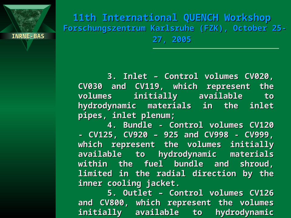
3. Inlet – Control volumes CV020, CV030 3. Inlet – Control volumes CV020, CV030 and CV119, which represent the volumes initially and CV119, which represent the volumes initially available to hydrodynamic materials in the inlet available to hydrodynamic materials in the inlet pipes, inlet plenum;pipes, inlet plenum;
4. Bundle - Control volumes CV120 - 4. Bundle - Control volumes CV120 - CV125, CV920 – 925 and CV998 - CV999, which CV125, CV920 – 925 and CV998 - CV999, which represent the volumes initially available to represent the volumes initially available to hydrodynamic materials within the fuel bundle and hydrodynamic materials within the fuel bundle and shroud, limited in the radial direction by the inner shroud, limited in the radial direction by the inner cooling jacket.cooling jacket.
5. Outlet – Control volumes CV126 and 5. Outlet – Control volumes CV126 and CV800, which represent the volumes initially CV800, which represent the volumes initially available to hydrodynamic materials in the outlet available to hydrodynamic materials in the outlet plenum and off-gas, pipe.plenum and off-gas, pipe.

INRNE-BASINRNE-BAS
11th International QUENCH Workshop11th International QUENCH Workshop Forschungszentrum Karlsruhe (FZK), October 25-27, 2005Forschungszentrum Karlsruhe (FZK), October 25-27, 2005
The Quench fuel rod bundle and Zircaloy The Quench fuel rod bundle and Zircaloy shroud are modeled with the Core (COR) Package. shroud are modeled with the Core (COR) Package. In the modeling of the COR package are used 88 In the modeling of the COR package are used 88 cells, in 4 rings, each with axial 22 levels. cells, in 4 rings, each with axial 22 levels.
The Axial COR Nodalization is divided into The Axial COR Nodalization is divided into 16 axial levels, each axial level having a height of 16 axial levels, each axial level having a height of 100 mm. The computational model includes two 100 mm. The computational model includes two additional levels below –300 mm and 4 additional additional levels below –300 mm and 4 additional levels above 1300 mm, to allow the proper of axial levels above 1300 mm, to allow the proper of axial boundary conditions. Another represents the 100 boundary conditions. Another represents the 100 mm section of the fuel rod simulators above the mm section of the fuel rod simulators above the outlet plenum that contain molybdenum outlet plenum that contain molybdenum electrodes. The uppermost and lowermost levels, electrodes. The uppermost and lowermost levels, with height 50 mm, represent the portion of the with height 50 mm, represent the portion of the fuel rod simulator, which are cooled by water. fuel rod simulator, which are cooled by water.

INRNE-BASINRNE-BAS
11th International QUENCH Workshop11th International QUENCH Workshop Forschungszentrum Karlsruhe (FZK), October 25-27, 2005Forschungszentrum Karlsruhe (FZK), October 25-27, 2005
The MELCOR HS Package calculates heat The MELCOR HS Package calculates heat condition within intact, solid structure and energy condition within intact, solid structure and energy transfer across its boundary surfaces into control transfer across its boundary surfaces into control volumes. There are 15 HS in COR Package. volumes. There are 15 HS in COR Package.
Boundary structures above insulation are 5 Boundary structures above insulation are 5 HS and below the jacket the numbers of HS are 3. HS and below the jacket the numbers of HS are 3.
If the heat structure is located at the outer If the heat structure is located at the outer radial boundary of the COR Package cells, the left radial boundary of the COR Package cells, the left boundary fluid temperature is calculated by the boundary fluid temperature is calculated by the COR Package. COR Package. Convective boundary conditions and Convective boundary conditions and radiation heat transfers are calculated on all radiation heat transfers are calculated on all surfaces, which are not insulated or cooled by surfaces, which are not insulated or cooled by water or argon. water or argon.
INRNE-BASINRNE-BAS
11th International QUENCH Workshop11th International QUENCH Workshop Forschungszentrum Karlsruhe (FZK), October 25-27, 2005Forschungszentrum Karlsruhe (FZK), October 25-27, 2005
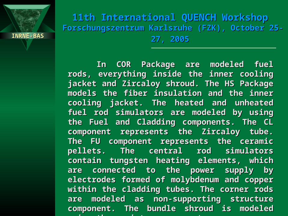
In COR Package are modeled fuel rods, In COR Package are modeled fuel rods, everything inside the inner cooling jacket and everything inside the inner cooling jacket and Zircaloy shroud. The HS Package models the fiber Zircaloy shroud. The HS Package models the fiber insulation and the inner cooling jacket. The heated insulation and the inner cooling jacket. The heated and unheated fuel rod simulators are modeled by and unheated fuel rod simulators are modeled by using the Fuel and Cladding components. The CL using the Fuel and Cladding components. The CL component represents the Zircaloy tube. The FU component represents the Zircaloy tube. The FU component represents the ceramic pellets. The component represents the ceramic pellets. The central rod simulators contain tungsten heating central rod simulators contain tungsten heating elements, which are connected to the power supply elements, which are connected to the power supply by electrodes formed of molybdenum and copper by electrodes formed of molybdenum and copper within the cladding tubes. The corner rods are within the cladding tubes. The corner rods are modeled as non-supporting structure component. modeled as non-supporting structure component. The bundle shroud is modeled using the canister The bundle shroud is modeled using the canister components. components.

INRNE-BASINRNE-BAS
CV119
CV120
CV121
CV122
C V 9 9 9
C V 9 9 8CV123
CV004
CV250
CV124
CV125
CV920
CV921
CV922
CV923
CV924
CV925
CV126
CV130
CV150
CV050
Ar source
CV001
CV002
CV003
Ar Source
SteamSource to LP
QuenchWater to LP
W
Mo
FL121
CV020
CV030
Ar
co olin
g jac
ket
Water cooling jacket CV800
FL001
FL002
FL003FL031
FL021
Lower Plenum
Upper Plenum
FL122
FL123
FL124
FL25
FL120
FL126
FL921
FL922
FL923
FL924
FL925
FL004
FL201
-475 mm
-300 mm
0 mm
300 mm
600 mm
800 mm
1024 mm
1300 mm
1500 mm
INRNE-BASINRNE-BAS
11th International QUENCH Workshop11th International QUENCH Workshop Forschungszentrum Karlsruhe (FZK), October 25-27, 2005Forschungszentrum Karlsruhe (FZK), October 25-27, 2005
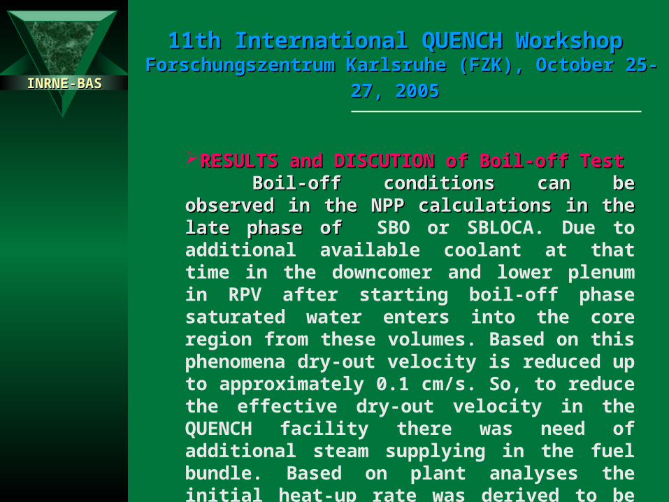
RESULTS and DISCUTION of Boil-off TestRESULTS and DISCUTION of Boil-off TestBoil-off conditions can be observed in the Boil-off conditions can be observed in the
NPP calculations in the late phase of NPP calculations in the late phase of SBO or SBLOCA. Due to additional available coolant at that time in the downcomer and lower plenum in RPV after starting boil-off phase saturated water enters into the core region from these volumes. Based on this phenomena dry-out velocity is reduced up to approximately 0.1 cm/s. So, to reduce the effective dry-out velocity in the QUENCH facility there was need of additional steam supplying in the fuel bundle. Based on plant analyses the initial heat-up rate was derived to be approximately 0.5 K/s.

INRNE-BASINRNE-BAS
11th International QUENCH Workshop11th International QUENCH Workshop Forschungszentrum Karlsruhe (FZK), October 25-27, 2005Forschungszentrum Karlsruhe (FZK), October 25-27, 2005
It have been used for calculation presented below input data based on draft test protocol of Quench L-Q2. Some insignificant deviation have been done based on discussions from previous slide. Water injection (g/s) Heaters power (W) Auxiliary heaters power (W)0.0 0.100 0.0 100.0 0.0 0.090.0 0.100 8.0 100.0 49.0 0.091.0 0.0 10.0 2500.0 50.0 1000.03299.0 0.0 1999.0 2500.0 3000.0 1000.03500.0 0.001 2000.0 5500.0 3300.0 3000.08300.0 0.001 3599.0 5500 5400.0 3000.08301.0 0.020 3600.0 6200.0 5499.0 3000.08569.0 0.020 4809.0 6200.0 5500.0 2200.08570.0 0.003 4810.0 6000.0 6600.0 2200.08700.0 0.003 4890.0 6500.0 8299.0 2200.08850.1 0.001 5000.0 7500.0 8300.0 2300.09000.0 0.0 8299.0 7500.0 8301.0 0.0
8300.0 7000.0 9000.0 0.08301.0 4000.08700.0 4000.08710.0 100.09000.0 100.0

INRNE-BASINRNE-BAS
11th International QUENCH Workshop11th International QUENCH Workshop Forschungszentrum Karlsruhe (FZK), October 25-27, 2005Forschungszentrum Karlsruhe (FZK), October 25-27, 2005
Some of important parameters during the Boil-off test are shown in next three figures. The calculation was performed up to 9000.0 sec into the transient time.
Coolant temperature in the Bundle Fuel Cladding Temperature

INRNE-BASINRNE-BAS
11th International QUENCH Workshop11th International QUENCH Workshop Forschungszentrum Karlsruhe (FZK), October 25-27, 2005Forschungszentrum Karlsruhe (FZK), October 25-27, 2005
The test section is filled up from 0 s to 90 s at approximately 1.1 m water level with flow rate of 100 g/s cold water (initial temperature is 363 K) and heat up with initial bundle power 2.5 kW to the saturated temperature, which is approximately 393 K. The pressure in the bundle is 0.2 MPa. There is injection of 3g hot Ar at the top from 0 s during the whole transient, and injection from the bottom with approximately of 2-3 g/s hot Ar to 8300 s.
The test starts with initial boil-off phase, which is controlled with the bundle heating system. To avoid increasing of cladding temperature in the upper part of bundle, start injection of additional water 1.0 g/s (the temperature of injected water is 363 K) at 3500 s and heated up injected water with 3 kW auxiliary heaters power.

INRNE-BASINRNE-BAS
11th International QUENCH Workshop11th International QUENCH Workshop Forschungszentrum Karlsruhe (FZK), October 25-27, 2005Forschungszentrum Karlsruhe (FZK), October 25-27, 2005
The auxiliary heaters are located at the lower plenum of the test facility. In this phase a Boil-off velocity is approximately 0.1 cm/s until reaching water level of 0.25 m at the lower end of the bundle. The heated rate is 0.45 K/s.
The reflood phase is initiated with injections of 20 g/s reflood water from quenching pump (See Table 1) at 8300 s, when peak bundle temperature reached value > 1837 K. The temperature in bundle didn’t reach the desired value > 1900 K. Reflood water temperature at lower end of the bundle is approximately 363 K. Cold water from the quench pump is heated up in the quench pipe and enters the lower plenum volumes.

INRNE-BASINRNE-BAS
11th International QUENCH Workshop11th International QUENCH Workshop Forschungszentrum Karlsruhe (FZK), October 25-27, 2005Forschungszentrum Karlsruhe (FZK), October 25-27, 2005
During reflood phase, the auxiliary heaters were terminated and the bundle heaters power was reduced to the decay heat level of 4 kW. Injection of reflood water is terminated when water level in the bundle reached 1.1 m.
Water Level in the Bundle

INRNE-BASINRNE-BAS
11th International QUENCH Workshop11th International QUENCH Workshop Forschungszentrum Karlsruhe (FZK), October 25-27, 2005Forschungszentrum Karlsruhe (FZK), October 25-27, 2005
CONCLUSIONS
This pre-test calculation shows that this test can be conducted successfully and observe the degraded core reflood and includes the preceding of boil-off phase up to the time, when the water has dropped to the lower end of the bundle during the Boil-off test with Quench facility.