input and output devices - people at vt computer...
TRANSCRIPT

Input and Output Devices
Joseph J. LaViola Jr. Input and Output Devices
Input and Output DevicesJoseph J. LaViola Jr.Brown University Compter Graphics Lab
Input and Output Devices for 3D Interaction
Joseph J LaViola Jr
Ph.D Student
Brown University,
Department of Computer Science
Providence, Rhode Island
Lead Consultant and Founder
JJL Interface Consultants, Inc.
http: http://www.cs.brown.edu/people/jjl
email: [email protected]

Input and Output Devices
Joseph J. LaViola Jr. Input and Output Devices2
Goals• Provide practical introduction to the
hardware required for Virtual Environment and 3D interaction
• Examine common and state of the art I/O devices
• Advantages and disadvantages • Discuss how different I/O devices affect
interface design
In this lecture we will discuss the various input and output devices that are used in 3D user interfaces and virtual environment applications.

Input and Output Devices
Joseph J. LaViola Jr. Input and Output Devices3
Lecture Outline• Output devices
• visual displays
• audio output
• tactile and haptic output
• Input devices• discrete event devices
• continuous event devices
• combination devices
• speech input
The first part of the lecture will describe a number of output devices that stimulate the human visual, auditory, haptic, and tactile systems. In the second part of the lecture, we will look at the many different ways a user can interface to a 3D world. With each device, we will discuss the advantages, disadvantages, and its effects on interface design.

Input and Output Devices
Joseph J. LaViola Jr. Input and Output Devices4
Visual Displays• Fully Immersive displays
• head mounted display
• arm mounted display (BOOM)
• virtual retinal display
• Semi Immersive (e.g. Fish Tank) displays• surround screen virtual environment (SSVR)
• Immersadesk and variants
• stereo monitor
• Other displays
In virtual environment applications, there have been two traditional methods for presenting the user with visual information. The first method, fully immersive display, completely blocks out the real world from the user. The second method, “fish tank” display, gives the user the ability to see both the real world and the virtual world. We will see that there are advantages and disadvantages to both these display methods.

Input and Output Devices
Joseph J. LaViola Jr. Input and Output Devices5
Head Mounted Displays• Device has either two
CRT or LCD screens plus special optics in front of the users eyes
• User cannot naturally see the real world
• Provides a stereoscopic view that moves relative to the user
One of the most common display devices used for virtual environment applications is the head mounted display (HMD). With a tracking device attached to the device, it produces a stereoscopic view that moves relative to the user’s head position and orientation.
Although the user cannot naturally see the real world, cameras are sometimes mounted on the HMD which allows it to display both real world video and graphical objects. This type of technology is used in some augmented reality systems.
References:
www.nvis.com
www.virtualresearch.com
www.stereo3d.com
Input and Output Devices
Joseph J. LaViola Jr. Input and Output Devices6
HMDs – Advantages• Provides an immersive experience by
blocking out the real world• Fairly easy to set up• Does not restrict user from moving around
in the real world• Average quality HMD is relatively
inexpensive• Can achieve good stereo quality
Since each eye is presented with one screen, HMDs allow for good stereoscopic viewing. These two screens are very close to the user’s eyes (1 to 2 inches). As a result, all viewable objects are behind the screen so any object clipping will appear to the user as being outside his/her field of view. The other advantages are shown in the slide.
Input and Output Devices
Joseph J. LaViola Jr. Input and Output Devices7
HMDs – Disadvantages• Average quality HMDs have poor
resolution and field of view (FOV)• Does not take advantage of peripheral
vision• Isolation and fear of real world events• Good quality devices cost in the 100,000
dollar range• Heavy and do not fit well
A big disadvantage of HMDs is that can get heavy very quickly and, unfortunately, the higher the HMD’s quality, the heavier it usually is. Although HMDs are still popular in many VR labs and entertainment centers, researchers and practitioners are rapidly moving towards projection-based display devices.

Input and Output Devices
Joseph J. LaViola Jr. Input and Output Devices8
HMDs – Interface Design• Physical objects require a graphical
representation• Limits the types of input devices that can
be used
Since the real world is completely blocked out of the user’s view, interaction while wearing an HMD requires the user to have some type of graphical representation of either one or both hands or the input device used. These graphical representations can be as simple as a cube or as complicated as a hand model containing 50000 or more polygons. HMDs also put a strain on the types of input devices that can be used since the user cannot physically see the device in order to use it.

Input and Output Devices
Joseph J. LaViola Jr. Input and Output Devices9
Arm Mounted Display (BOOM)• Like a HMD but
mounted on an articulated arm
• Mostly use CRT technology
• Most common arm mounted displays developed byFakespace
The arm mounted display shown in the picture is called a BOOM developed byFakespace. It has a counter weight on the the opposite side of the display to make the device easier to manipulate. The device also uses mechanical tracking technology to track the user’s head position and orientation.
References:
www.fakespace.com

Input and Output Devices
Joseph J. LaViola Jr. Input and Output Devices10
BOOM – Advantages• Provides better resolution than HMDs and
generally a higher FOV• Light weight relative to the user• Excellent tracking with minimal lag• Easy to set up and switch users • Good stereo quality
The latest version of the BOOM supports resolutions of 1280x1024 pixels per eye which is better than most average quality HMDs. Since the user does not have to wear the device, it is easy to operate and allows for different users to trade places quickly. As with the HMD, providing one screen per eye allows for good stereo quality.

Input and Output Devices
Joseph J. LaViola Jr. Input and Output Devices11
BOOM – Disadvantages• Limited user movement• Like looking through binoculars• Does not take advantage of peripheral
vision• Requires the user to hold onto the BOOM
for control
Since the BOOM is physically attached to a large stand, the user’s movement is limited. Users can move in about a six foot diameter around the center of the stand.

Input and Output Devices
Joseph J. LaViola Jr. Input and Output Devices12
BOOM – Interface Design• Must have at least one hand on the device
which limits two-handed interaction• Physical objects require graphical
representation
As with HMDs, physical objects require graphical representations.
Input and Output Devices
Joseph J. LaViola Jr. Input and Output Devices13
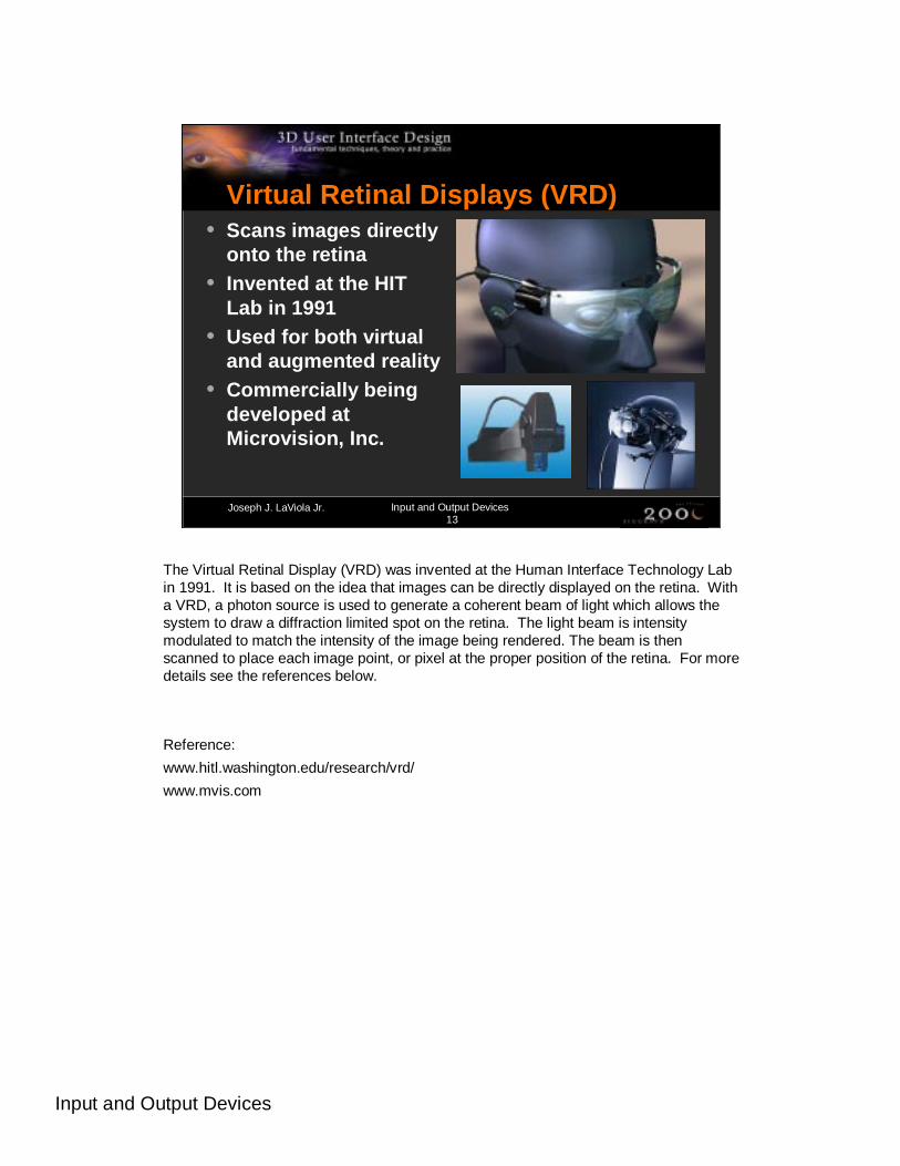
Virtual Retinal Displays (VRD)• Scans images directly
onto the retina• Invented at the HIT
Lab in 1991• Used for both virtual
and augmented reality • Commercially being
developed atMicrovision, Inc.
The Virtual Retinal Display (VRD) was invented at the Human Interface Technology Lab in 1991. It is based on the idea that images can be directly displayed on the retina. With a VRD, a photon source is used to generate a coherent beam of light which allows the system to draw a diffraction limited spot on the retina. The light beam is intensity modulated to match the intensity of the image being rendered. The beam is then scanned to place each image point, or pixel at the proper position of the retina. For more details see the references below.
Reference:
www.hitl.washington.edu/research/vrd/
www.mvis.com
Input and Output Devices
Joseph J. LaViola Jr. Input and Output Devices14
VRDs – Advantages• Lightweight relative to the user• Ability for high resolution and FOV• Potential for complete visual immersion• Can achieve good stereo quality
The biggest advantage of VRDs is that they theoretically could encompass the user’s entire visual field which would provide complete visual immersion.

Input and Output Devices
Joseph J. LaViola Jr. Input and Output Devices15
VRDs – Disadvantages• Currently has low resolution and FOV is
small• Displays are currently monochrome
VRD technology is still in its infancy and, as a result, the available devices are no better than HMDs in terms of visual quality. However, they do show promise as an ideal virtual reality display device.
Input and Output Devices
Joseph J. LaViola Jr. Input and Output Devices16
VRDs – Interface Design• Avenue of research• Questions arise about eye movement
Since VRDs are so new and generally uncommon in most academic, industrial, and government VR research labs, interface design issues with these devices have been relatively unexplored.
Input and Output Devices
Joseph J. LaViola Jr. Input and Output Devices17
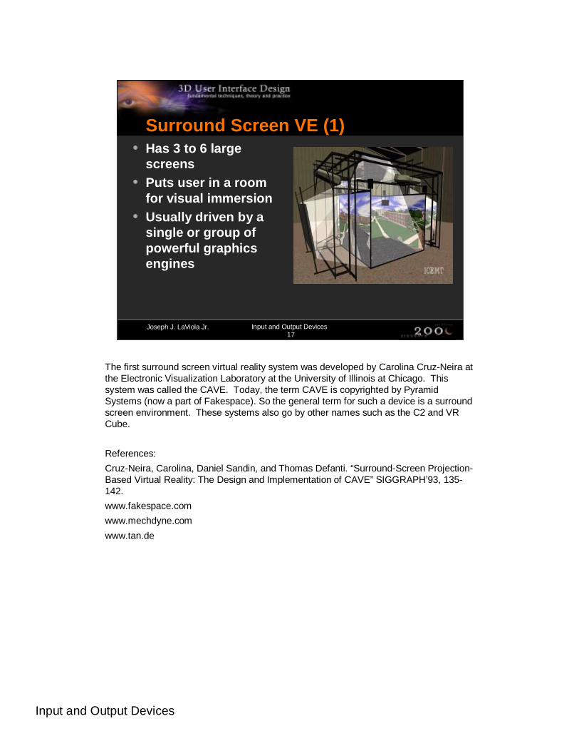
Surround Screen VE (1)• Has 3 to 6 large
screens• Puts user in a room
for visual immersion• Usually driven by a
single or group of powerful graphics engines
The first surround screen virtual reality system was developed by Carolina Cruz-Neira at the Electronic Visualization Laboratory at the University of Illinois at Chicago. This system was called the CAVE. Today, the term CAVE is copyrighted by Pyramid Systems (now a part of Fakespace). So the general term for such a device is a surround screen environment. These systems also go by other names such as the C2 and VR Cube.
References:
Cruz-Neira, Carolina, Daniel Sandin, and Thomas Defanti. “Surround-Screen Projection-Based Virtual Reality: The Design and Implementation of CAVE” SIGGRAPH’93, 135-142.
www.fakespace.com
www.mechdyne.com
www.tan.de

Input and Output Devices
Joseph J. LaViola Jr. Input and Output Devices18
Surround Screen VE (2)
The picture shows a 6-sided TAN VR Cube installed at the VR-Center Nord, Alborg, Denmark. The Royal Institute for Parallel Computing in Stockholm, Sweden also has a 6-sided VR Cube. Iowa State University is also developing a 6 sided surround screen VE called the C6.

Input and Output Devices
Joseph J. LaViola Jr. Input and Output Devices19
Surround Screen VE (3)
The figures in the slide show the RAVE, a reconfigurable advanced visualization environment developed by Fakespace. It is designed to be a flexible display device which can be used as a 30 foot flat wall, a 30 foot variable angle immersive theatre, a Cave-like three wall and floor immersive environment, an L-shaped cove with separate 10 foot wall, and three separate 10 foot review walls.

Input and Output Devices
Joseph J. LaViola Jr. Input and Output Devices20
SSVR – Advantages• Provides high resolution and large FOV• User only needs a pair of light weight shutter
glasses for stereo viewing• User has freedom to move about the device• Environment is not evasive• Real and virtual objects can be mixed in the
environment• A group of people can inhabit the space
simultaneously
There are a number of advantages of SSVR systems as shown in the slide.
Input and Output Devices
Joseph J. LaViola Jr. Input and Output Devices21
SSVR – Disadvantages• Very expensive (approximately 1 million
dollars)• Requires a large amount of physical space• Projector calibration must be maintained• No more that two users can be head
tracked• Stereo viewing can be problematic• Physical objects can get in the way of
graphical objects
One of the biggest disadvantages of SSVR systems is the fact that they are so expensive and require such a large amount of physical space. Another problem with an SSVR system, as well as any projection-based display system, is stereo viewing can be problematic. When the user gets close to the display or when objects appear to be right in front of the user, it becomes more and more difficult to fuse the two images together. Eye strain is a common problem in these situations.
Input and Output Devices
Joseph J. LaViola Jr. Input and Output Devices22
SSVR – Interface Design• Do not need to represent physical objects
(i.e. hands) as graphical objects• Can take advantage of the user’s
peripheral vision• Do not want the user to get too close to
the screens• Developer can take advantage of the
space for using physical props (i.e. car, motion platform)
Although physical objects do not have to be represented as graphical objects in SSVR systems, an important issue arises when a physical object passes in front of graphical objects that should appear in front of the said physical object. This is a common problem with any projection-based display device and can hinder the immersive experience.
In most cases the user wears a pair of shutter glasses for stereo viewing. These glasses are synched to flicker at a rate equal to the refresh rate of the graphics engine. These signals are sent to the glasses by infrared signal. So, if the signal is blocked, the shutter glasses will stop working and the stereo effect will be disrupted. As a general guideline, it is a good idea to never have the user move his/her hands or other physical objects in the line of sight of the glasses and emitters.
Input and Output Devices
Joseph J. LaViola Jr. Input and Output Devices23
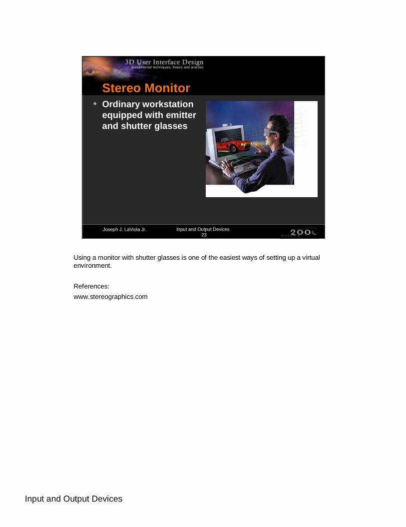
Stereo Monitor• Ordinary workstation
equipped with emitter and shutter glasses
Using a monitor with shutter glasses is one of the easiest ways of setting up a virtual environment.
References:
www.stereographics.com

Input and Output Devices
Joseph J. LaViola Jr. Input and Output Devices24
Stereo Monitor – Advantages• Least expensive in terms of additional
hardware over other output devices• Allows usage of virtually any input device• Good resolution• User can take advantage of keyboard and
mouse
Stereo monitors have the advantages shown in the slide.

Input and Output Devices
Joseph J. LaViola Jr. Input and Output Devices25
Stereo Monitor – Disadvantages• Not very immersive• User really cannot move around• Does not take advantage of peripheral
vision• Stereo can be problematic• Occlusion from physical objects can be
problematic
Stereo monitors have a number of disadvantages shown in the slide.

Input and Output Devices
Joseph J. LaViola Jr. Input and Output Devices26
Stereo Monitor – Interface Design• Allows for more flexibility in interface
mappings from input device to task
The nice thing about stereo monitors is that there a great number of interface mappings from device to task. The big reason for this is that the users have the keyboard in front of them.
Input and Output Devices
Joseph J. LaViola Jr. Input and Output Devices27
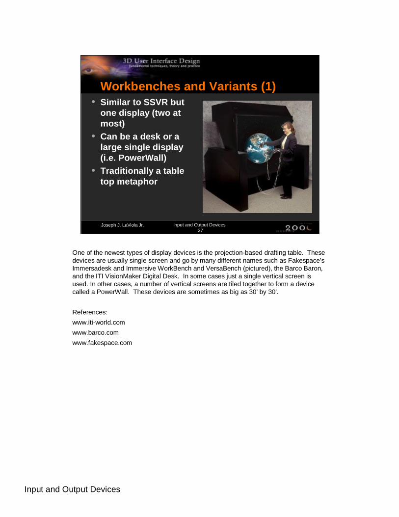
Workbenches and Variants (1)• Similar to SSVR but
one display (two at most)
• Can be a desk or a large single display (i.e. PowerWall)
• Traditionally a table top metaphor
One of the newest types of display devices is the projection-based drafting table. These devices are usually single screen and go by many different names such as Fakespace’s Immersadesk and Immersive WorkBench and VersaBench (pictured), the Barco Baron, and the ITI VisionMaker Digital Desk. In some cases just a single vertical screen is used. In other cases, a number of vertical screens are tiled together to form a device called a PowerWall. These devices are sometimes as big as 30’ by 30’.
References:
www.iti-world.com
www.barco.com
www.fakespace.com
Input and Output Devices
Joseph J. LaViola Jr. Input and Output Devices28
Workbenches and Variants (2)
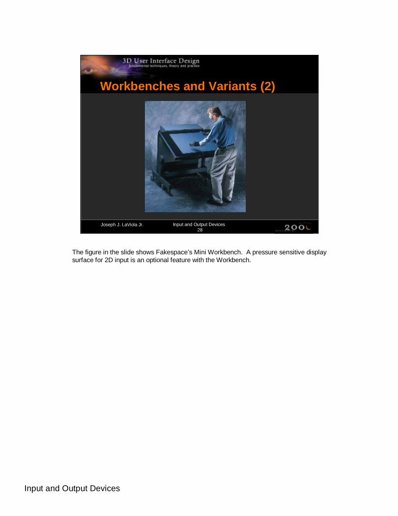
The figure in the slide shows Fakespace’s Mini Workbench. A pressure sensitive display surface for 2D input is an optional feature with the Workbench.

Input and Output Devices
Joseph J. LaViola Jr. Input and Output Devices29
Workbenches and Variants (3)
The figures in the slide show the TAN Holobench, an L-shaped desk which provides a holographic impression since objects appear to be raised above the desk.

Input and Output Devices
Joseph J. LaViola Jr. Input and Output Devices30
Workbenches – Advantages• High resolution• For certain applications, makes for an
intuitive display• Can be shared by several users
Even though a number of users can gather around these projection tables, no more than 2 users can view the desk in head-tracked stereo.

Input and Output Devices
Joseph J. LaViola Jr. Input and Output Devices31
Workbenches – Disadvantages• Limited movement• At most two users can be head tracked• No surrounding screens• Physical objects can get in the way of
graphical objects• Stereo can be problematic
There are a number of disadvantages with projection-based table devices as shown in the slide.

Input and Output Devices
Joseph J. LaViola Jr. Input and Output Devices32
Workbenches – Interface Design• Ergonomics are important especially when
designing interfaces for table displays• User can take advantage of direct pen-
based input if display surface permits• No need to make graphical
representations of physical objects
These types of display devices have the same problem with stereo viewing and physical/graphical object conflict that SSVR and stereo monitors have.
Input and Output Devices
Joseph J. LaViola Jr. Input and Output Devices33
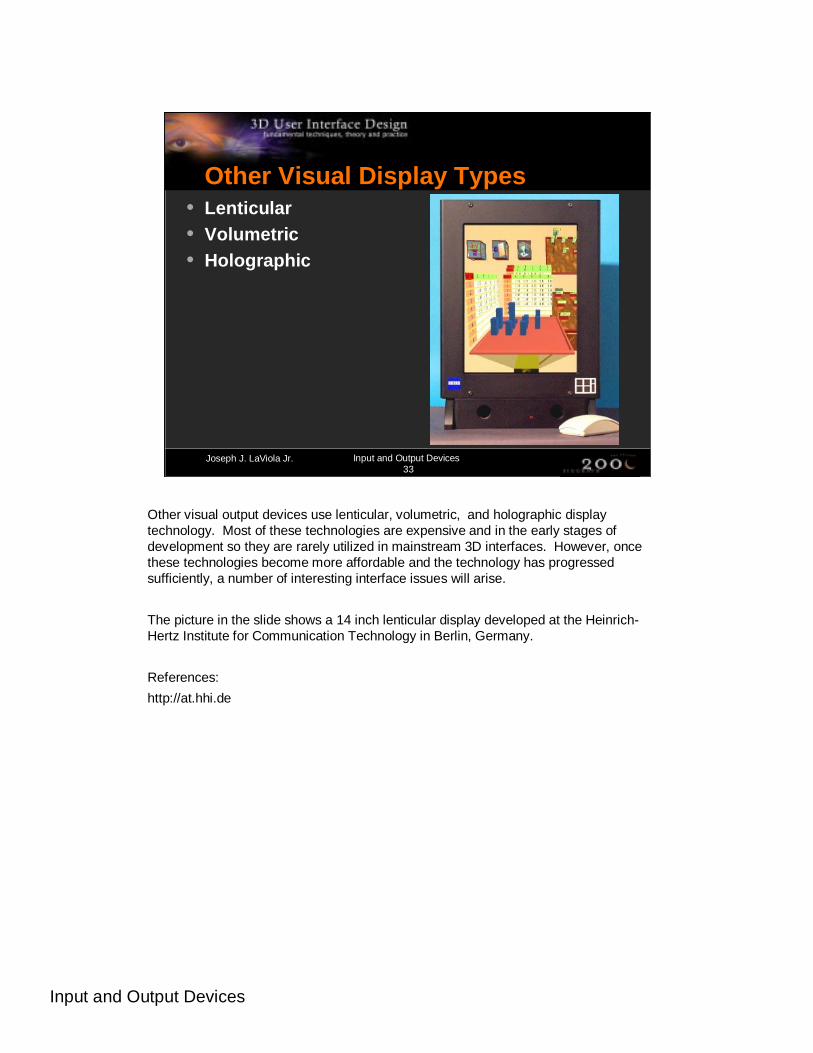
Other Visual Display Types• Lenticular• Volumetric• Holographic
Other visual output devices use lenticular, volumetric, and holographic display technology. Most of these technologies are expensive and in the early stages of development so they are rarely utilized in mainstream 3D interfaces. However, once these technologies become more affordable and the technology has progressed sufficiently, a number of interesting interface issues will arise.
The picture in the slide shows a 14 inch lenticular display developed at the Heinrich-Hertz Institute for Communication Technology in Berlin, Germany.
References:
http://at.hhi.de

Input and Output Devices
Joseph J. LaViola Jr. Input and Output Devices34
Auditory Displays• Main Challenges
• localization
• sonification
• Many different types of setups
There are two different ways, localization and sonification, in which sound can be used as an output medium in virtual environment applications. In localization, the goal is to generate three dimensional sound. In sonification, the goal is to turn certain types of information into sounds.
There are a number of different ways in which an auditory system can be setup. A simple setup is to use stereo head phones. However, this restricts usage to only one person at a time. Another setup is to place speakers in certain logistic areas around the environment. This setup allows for more than one user to take part in the experience but is somewhat more complicated to setup and write software for.
Reference:
Begault, Durand R. 3D Sound For Virtual Reality and Multimedia. Academic Press, 1994.

Input and Output Devices
Joseph J. LaViola Jr. Input and Output Devices35
Auditory Output – Interface Design• If used properly can be a powerful tool• Tells user something important is
happening and where to look for it• Provides sensory substitution
Auditory output can be very powerful when applied correctly in 3D virtual environments. It is especially useful in collaborative applications where participants can get a sense for where others are in the environment. It also can be used for sensory substitution which is important when, for example, no haptic or tactile feedback is present. A sound could substitute the feel of a button press or the moving of an object in the virtual space.

Input and Output Devices
Joseph J. LaViola Jr. Input and Output Devices36
Haptic and Tactile Feedback (1)• “For every action there is
an equal and opposite reaction”• Sir Issac Newton
• Main forms of feedback• ground referenced
(ex. Phantom)
• body referenced (ex. CyberGrasp)
• tactile (ex. CyberTouch)
• dermal tactile (ex. None)
Haptics represents a critical component in virtual environment interaction. Allowing a user to touch and feel in the virtual world in the same way that they do in the physical world is extremely powerful. Unfortunately, haptic and tactile output device research is still in its early stages.
There are essentially four different methods in which haptic and tactile feedback is generated. The first method is ground-referenced feedback which creates a physical link between the user and ground with the feedback relative to a single contact point. An example shown in the bottom picture is Virtual Technologies’ CyberForce. The second method is body-referenced feedback which places a device on some part of the user’s body. An example of a body-referenced haptic device is Virtual Technologies’ CyberGrasp which is shown in the top picture. The third method for generating feedback is tactile which uses some type of oscillatory or vibrating device to stimulate the user’s tactile sense. Finally, the last method of generating feedback is via dermal tactile which stimulates the user’s nerves in the fingertips.
References:
www.sensable.com
www.virtex.com
Input and Output Devices
Joseph J. LaViola Jr. Input and Output Devices37
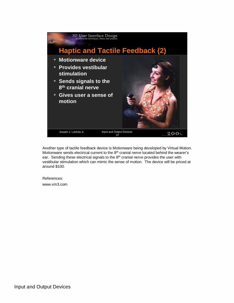
Haptic and Tactile Feedback (2)• Motionware device• Provides vestibular
stimulation• Sends signals to the
8th cranial nerve• Gives user a sense of
motion
Another type of tactile feedback device is Motionware being developed by Virtual Motion. Motionware sends electrical current to the 8th cranial nerve located behind the wearer’s ear. Sending these electrical signals to the 8th cranial nerve provides the user with vestibular stimulation which can mimic the sense of motion. The device will be priced at around $100.
References:
www.vm3.com

Input and Output Devices
Joseph J. LaViola Jr. Input and Output Devices38
Haptics – Interface Design• Useful for object
manipulation• Problem with these
devices is they are very intimidating
• Mimic real world interaction
Haptic feedback from devices like the CyberGrasp are very good for grabbing objects and moving them around and they can provide a limited form of real world interaction. The main problem with these devices is that they are somewhat intimidating to the user. People are commonly afraid to put these devices on and once they do they’re afraid they’ll break them or get injured. The picture shows the Phantom 3.0 from SensableTechnologies. This device is less intrusive than the CyberGrasp.
References:
Burdea, Grigore C. Force and Touch Feedback for Virtual Reality. Wiley Interscience, 1996.
Input and Output Devices
Joseph J. LaViola Jr. Input and Output Devices39
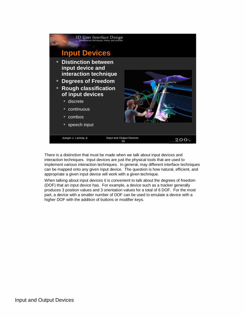
Input Devices• Distinction between
input device and interaction technique
• Degrees of Freedom• Rough classification
of input devices• discrete
• continuous
• combos
• speech input
There is a distinction that must be made when we talk about input devices and interaction techniques. Input devices are just the physical tools that are used to implement various interaction techniques. In general, may different interface techniques can be mapped onto any given input device. The question is how natural, efficient, and appropriate a given input device will work with a given technique.
When talking about input devices it is convenient to talk about the degrees of freedom (DOF) that an input device has. For example, a device such as a tracker generally produces 3 position values and 3 orientation values for a total of 6 DOF. For the most part, a device with a smaller number of DOF can be used to emulate a device with a higher DOF with the addition of buttons or modifier keys.
Input and Output Devices
Joseph J. LaViola Jr. Input and Output Devices40
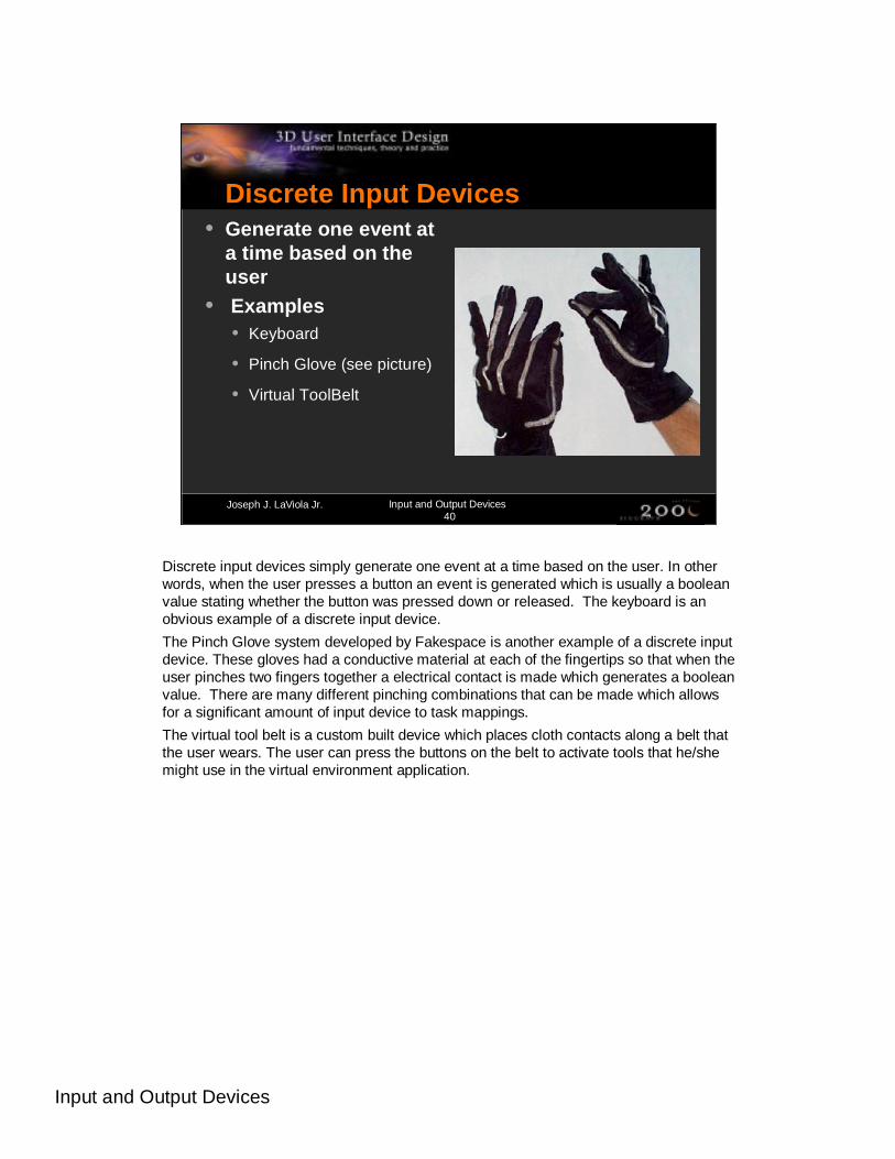
Discrete Input Devices• Generate one event at
a time based on the user
• Examples• Keyboard
• Pinch Glove (see picture)
• Virtual ToolBelt
Discrete input devices simply generate one event at a time based on the user. In other words, when the user presses a button an event is generated which is usually a booleanvalue stating whether the button was pressed down or released. The keyboard is an obvious example of a discrete input device.
The Pinch Glove system developed by Fakespace is another example of a discrete input device. These gloves had a conductive material at each of the fingertips so that when the user pinches two fingers together a electrical contact is made which generates a booleanvalue. There are many different pinching combinations that can be made which allows for a significant amount of input device to task mappings.
The virtual tool belt is a custom built device which places cloth contacts along a belt that the user wears. The user can press the buttons on the belt to activate tools that he/she might use in the virtual environment application.

Input and Output Devices
Joseph J. LaViola Jr. Input and Output Devices41
Continuous Input Devices• Continuously
generate events in isolation or in response to user action
• Examples• trackers
• datagloves
• Cyberlink
Continuous input devices generate a continual stream of events in isolation (no user manipulation) or in response to user action. For example, a tracker is a device which will continually output position and orientation records even if the device is not moving. These types of devices are important when we want to know where something is in the virtual space and we do not want to have to keep asking for it. A perfect example of this is head tracking. Two of the most common continuous devices are trackers anddatagloves. Data gloves transmit records on the bend angles of the fingers.
Another type of continuous input device is the Cyberlink, a brain-body actuated control technology that combines eye-movement, facial muscle, and brain wave bio-potentials to generate input signals. The Cyberlink has three sensors in a headband and its interface unit amplifies and translates the brain wave, facial muscle and eye-movement data into separate frequencies and transmits them to an PC serial port. The Cyberlink software processes and displays theses frequencies and 10 continuous command signals called Brainfingers.
References:
www.brainfingers.com

Input and Output Devices
Joseph J. LaViola Jr. Input and Output Devices42
Trackers• Goals and importance
• provide correct viewing perspective
• correspondence between physical and virtual worlds
• Types of trackers• magnetic
• mechanical
• acoustic
• inertial
• vision/camera
• hybrids
One of the most important aspects of 3D interaction in virtual worlds is providing a correspondence between the physical and virtual environments. As a result, having accurate tracking is extremely important to making the VE usable. Currently there are a number of different tracking technologies in the marketplace. The different types are shown in the slide. The next few slides will go over each type of technology.

Input and Output Devices
Joseph J. LaViola Jr. Input and Output Devices43
Magnetic Trackers• Example: Ascension Bird• Advantages
• good range
• no line of sight issues
• moderately priced
• Disadvantages• metal or conductive material
will distort the magnetic field
• magnetic field can interfere with nearby monitors
Magnetic tracking uses a transmitting device that emits a low frequency magnetic field that a small sensor, the receiver, uses to determine its position and orientation relative to a magnetic source. These trackers can use extended range transmitters which increase the range of the device from around an 8 foot radius to anywhere from a 15 to 30 foot radius. The tracker shown in the picture is called the Ascension MiniBird. It uses a smaller emitter and receivers and has better accuracy than the regular system. However it’s range is limited to about a 4 foot radius. It is primarily used in medical applications where range of the device is not a factor.
References:
www.ascension-tech.com
www.polhemus.com

Input and Output Devices
Joseph J. LaViola Jr. Input and Output Devices44
Mechanical Trackers• Example: Fakespace BOOM tracker• Advantages
• low latency
• very accurate
• Disadvantages• big and bulky
• usually only one sensor
• reduced mobility
• expensive
Mechanical trackers have a rigid structure with a number of joints. One end is fixed in place while the other is attached to the object to be tracked (usually the user’s head). The joint angles are used to obtain position and orientation records. The FakespaceBOOM uses this type of tracking technology.
References:
www.fakespace.com
Input and Output Devices
Joseph J. LaViola Jr. Input and Output Devices45
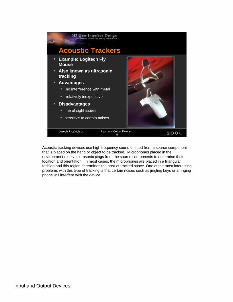
Acoustic Trackers• Example: Logitech Fly
Mouse• Also known as ultrasonic
tracking• Advantages
• no interference with metal
• relatively inexpensive
• Disadvantages• line of sight issues
• sensitive to certain noises
Acoustic tracking devices use high frequency sound emitted from a source component that is placed on the hand or object to be tracked. Microphones placed in the environment receive ultrasonic pings from the source components to determine their location and orientation. In most cases, the microphones are placed in a triangular fashion and this region determines the area of tracked space. One of the most interesting problems with this type of tracking is that certain noises such as jingling keys or a ringing phone will interfere with the device.

Input and Output Devices
Joseph J. LaViola Jr. Input and Output Devices46
Inertial Tracking• Example: InterSense
IS300• Advantages
• no interference with metal
• long range
• no need for transmitter
• Disadvantages• subject to error accumulation
• sensors are somewhat larger than magnetic sensors
• only track orientation
Inertial tracking systems use a variety of inertial measurement devices such as gyroscopes, servo accelerometers, and micro-machined quartz tuning forks. Since the tracking system is in the sensor, range is limited to the length of the cord which attaches the sensor to the electronics box. Two of the big limitations of these devices is that they only track orientation and are subject to error accumulation. The InterSense IS300 (pictured) handles error accumulation by using a gravitometer and compass measurements to prevent accumulation of gyroscopic drift and also uses motion prediction to predict motion up to 50 milliseconds into the future.
Reference:
www.isense.com

Input and Output Devices
Joseph J. LaViola Jr. Input and Output Devices47
Camera/Vision Tracking• Example: video camera and workstation• Advantages
• accurate
• can capture a large volume
• allow for unobtrusive tracking
• Disadvantages• may require light emitting diodes(LEDs)
• may require image processing techniques
• suffers from the occlusion problem
Camera/vision based tracking takes one or more cameras and places them in the physical environment. The cameras then grab video of the user or object to be tracked. Usually image processing techniques, such as edge detection algorithms, are used to identify the position and/or orientation of various body parts such as the head and hands. Setting up vision-based tracking systems can be difficult since there are many parameters that must be fixed in order to track the user properly. These parameters include the number of cameras, the placement of the camera, what background (what is in back of the user) is put up, and if the user will be wearing special optical tools such asLEDs or colored gloves to aid in tracking.
The pictures in the slide shows Ascension’s laserBIRD optical tracking device. laserBIRD delivers accurate position and orientation tracking without environmental interference or distortion. Its miniaturized scanner reflects laser beams throughout the work space. Each sensor, attached to a tracked object, instantly picks up the laser beams. Signals are then directed back to the scanner’s DSP electronics for processing and transmission to a host PC or workstation.
References:
www.ascension-tech.com

Input and Output Devices
Joseph J. LaViola Jr. Input and Output Devices48
Hybrid Tracking• Example InterSense
IS600• Advantages
• puts two or more technologies together to improve accuracy, reduce latency, etc…
• Disadvantages• adds complexity
Hybrid trackers attempt to put more than one tracking technology together to help increase accuracy, reduce latency, and, in general, provide a better virtual environment experience. The device shown in the picture is the InterSense IS600. It combines inertial and ultrasonic tracking technologies which enables the device to attain 6 DOF. The major difficulty with hybrid trackers is that the more components added to the system, the more complex the device becomes.
Other types of hybrid tracking include the combination of video cameras and structured digital light projectors. Combining these two technologies allow for the capture of depth, color, and surface reflectance information for objects and participants in the environment. This approach is currently being used at the University of North Carolina, Chapel Hill in their Office of the Future project.
References:
www.isense.com
Raskar, Ramesh, Welch, Greg, et al. “The Office of the Future: A Unifyed Approach to Image-Based Modeling and Spatially Immersive Displays” SIGGRAPH ’98, ACM Press, 179-188.
Input and Output Devices
Joseph J. LaViola Jr. Input and Output Devices49
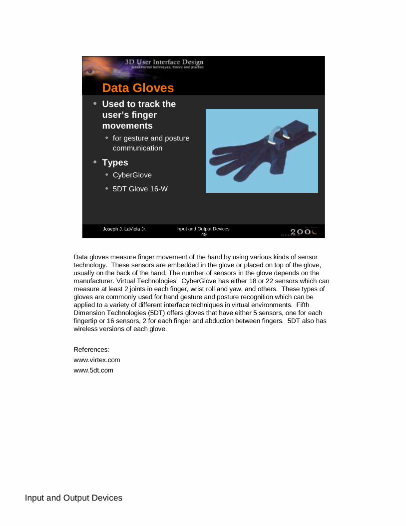
Data Gloves• Used to track the
user’s finger movements• for gesture and posture
communication
• Types• CyberGlove
• 5DT Glove 16-W
Data gloves measure finger movement of the hand by using various kinds of sensor technology. These sensors are embedded in the glove or placed on top of the glove, usually on the back of the hand. The number of sensors in the glove depends on the manufacturer. Virtual Technologies’ CyberGlove has either 18 or 22 sensors which can measure at least 2 joints in each finger, wrist roll and yaw, and others. These types of gloves are commonly used for hand gesture and posture recognition which can be applied to a variety of different interface techniques in virtual environments. Fifth Dimension Technologies (5DT) offers gloves that have either 5 sensors, one for each fingertip or 16 sensors, 2 for each finger and abduction between fingers. 5DT also has wireless versions of each glove.
References:
www.virtex.com
www.5dt.com
Input and Output Devices
Joseph J. LaViola Jr. Input and Output Devices50
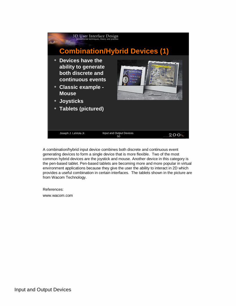
Combination/Hybrid Devices (1)• Devices have the
ability to generate both discrete and continuous events
• Classic example -Mouse
• Joysticks• Tablets (pictured)
A combination/hybrid input device combines both discrete and continuous event generating devices to form a single device that is more flexible. Two of the most common hybrid devices are the joystick and mouse. Another device in this category is the pen-based tablet. Pen-based tablets are becoming more and more popular in virtual environment applications because they give the user the ability to interact in 2D which provides a useful combination in certain interfaces. The tablets shown in the picture are from Wacom Technology.
References:
www.wacom.com
Input and Output Devices
Joseph J. LaViola Jr. Input and Output Devices51
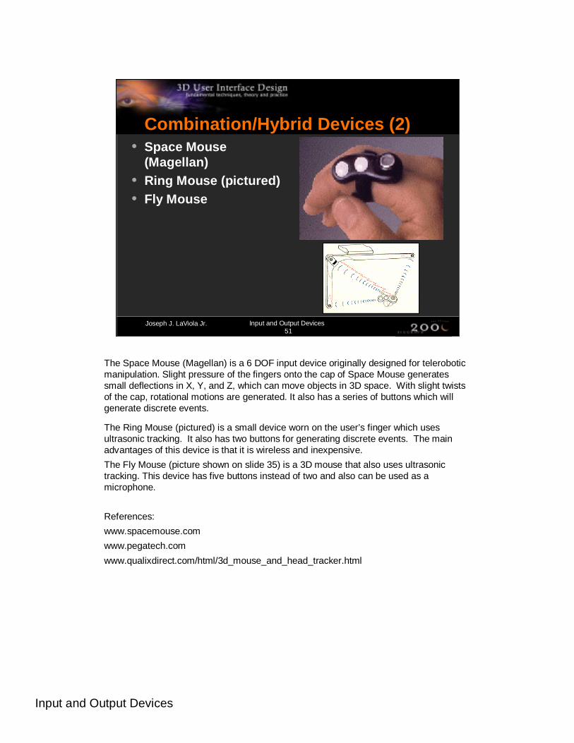
Combination/Hybrid Devices (2)• Space Mouse
(Magellan)• Ring Mouse (pictured)• Fly Mouse
The Space Mouse (Magellan) is a 6 DOF input device originally designed for teleroboticmanipulation. Slight pressure of the fingers onto the cap of Space Mouse generates small deflections in X, Y, and Z, which can move objects in 3D space. With slight twists of the cap, rotational motions are generated. It also has a series of buttons which will generate discrete events.
The Ring Mouse (pictured) is a small device worn on the user’s finger which uses ultrasonic tracking. It also has two buttons for generating discrete events. The main advantages of this device is that it is wireless and inexpensive.
The Fly Mouse (picture shown on slide 35) is a 3D mouse that also uses ultrasonic tracking. This device has five buttons instead of two and also can be used as a microphone.
References:
www.spacemouse.com
www.pegatech.com
www.qualixdirect.com/html/3d_mouse_and_head_tracker.html
Input and Output Devices
Joseph J. LaViola Jr. Input and Output Devices52
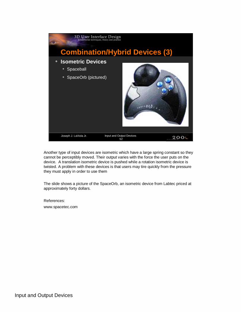
Combination/Hybrid Devices (3)• Isometric Devices
• Spaceball
• SpaceOrb (pictured)
Another type of input devices are isometric which have a large spring constant so they cannot be perceptibly moved. Their output varies with the force the user puts on the device. A translation isometric device is pushed while a rotation isometric device is twisted. A problem with these devices is that users may tire quickly from the pressure they must apply in order to use them
The slide shows a picture of the SpaceOrb, an isometric device from Labtec priced at approximately forty dollars.
References:
www.spacetec.com

Input and Output Devices
Joseph J. LaViola Jr. Input and Output Devices53
Combination/Hybrid Devices (4)• BAT• Wand• Flex and Pinch
(pictured)• Lego Interface Toolkit
The BAT is a device that was developed by Colin Ware in the late 1980’s. It essentially is just a tracking device with three buttons attached to it. It’s similar to the other 3D mice mentioned in the previous slide except it is rather easy to build one with a few electrical components (provided you have the tracking device). The Wand is a device that is commonly seen in SSVR environments. It is simply a more elegant version of the BAT that is commercially developed. The Flex and Pinch input system is a custom built device which takes the functionality of the Pinch Glove system and combines it with the bend sensing technology of a data glove. The pinch buttons are made from conductive cloth and can be placed anywhere on the bend sensing glove. The Lego Interface Toolkit is a rapid prototyping system for physical interaction devices in immersive environments. It utilizes Lego bricks because they are easily obtained and support a variety of physical configurations.
References:
Ware, Colin and Danny R. Jessome. “Using the Bat: A Six Dimensional Mouse for Object Placement.” Proceedings of Graphics Interface’88, 119-124.
LaViola, Joseph and Robert Zeleznik. “Flex and Pinch: A Case Study of Whole-Hand Input Design for Virtual Environment Interaction.” Proceedings of the IASTED International Conference on Computer Graphics and Imaging ’99, 221-225.
Ayers, Matthew and Robert Zeleznik. “The Lego Interface Toolkit.” Proceedings of User Interface Software and Technology, 1996, 97-98.
Input and Output Devices
Joseph J. LaViola Jr. Input and Output Devices54
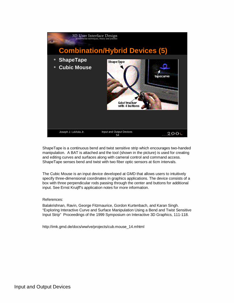
Combination/Hybrid Devices (5)• ShapeTape• Cubic Mouse
ShapeTape is a continuous bend and twist sensitive strip which encourages two-handed manipulation. A BAT is attached and the tool (shown in the picture) is used for creating and editing curves and surfaces along with cameral control and command access.ShapeTape senses bend and twist with two fiber optic sensors at 6cm intervals.
The Cubic Mouse is an input device developed at GMD that allows users to intuitively specify three-dimensional coordinates in graphics applications. The device consists of a box with three perpendicular rods passing through the center and buttons for additional input. See Ernst Kruijff’s application notes for more information.
References:
Balakrishnan, Ravin, George Fitzmaurice, Gordon Kurtenbach, and Karan Singh. “Exploring Interactive Curve and Surface Manipulation Using a Bend and Twist Sensitive Input Strip” Proceedings of the 1999 Symposium on Interactive 3D Graphics, 111-118.
http://imk.gmd.de/docs/ww/ve/projects/cub.mouse_14.mhtml

Input and Output Devices
Joseph J. LaViola Jr. Input and Output Devices55
Speech Input (1)• Provides complement to other modes of
interaction• Ideal for multimodal interaction
Speech input provides a nice complement to other input devices. As a result, it is a natural way to combine different modes of input (e.g. multimodal interaction) to form a more cohesive and natural interface. In general, when functioning properly speech input can be a valuable tool in virtual environment applications especially when both of the user’s hands are occupied.

Input and Output Devices
Joseph J. LaViola Jr. Input and Output Devices56
Speech Input (2)• Myth - Having a good speech recognizer
solves all problems• many other issues to consider
• continuous vs. one-time recognition• choice and placement of microphone• training vs. no training• handling of false positive recognition• surrounding noise interference
• Guideline – Use Implicit Push-to-talk
There are many issues to consider when dealing with speech input besides what speech recognition engine to use. There are tradeoffs that must be made when dealing with speech input. An important issue is where the microphone is to be placed. Ideally, a wide area mike would be best so that the user does not have to wear a headset. Placing such a microphone in the physical environment could be problematic since it might pick up noise from other people or machines in the room. One of the big problems with using speech input is having the computer know when to and not to listen to the user’s voice. Often, a user is conversing with a collaborator with no intention of issuing voice commands but the applications “thinks’’ the user is speaking to it. This misinterpretation can be very problematic. One of the best ways to avoid this problem is to use an implicit or invisible push-to-talk scheme. A push-to-talk scheme lets the user tell the application when he/she is speaking to it or someone else. In order to keep the naturalness of the speech interface, we do not want to have to add to the user’s cognitive load. The goal of implicit push-to-talk is to imbed the “push’’ into existing interaction techniques so the user does not have the burden of remembering to signal the application that a voice command is about to be issued.

Input and Output Devices
Joseph J. LaViola Jr. Input and Output Devices57
General Guidelines for Choosing I/O• Money is a big factor• Think about what interaction techniques
are required• Choosing input device restricts the choice
of output device• Choosing output device restricts the
choice of input device• Creativity is important
Obviously when choosing input and output devices for creating virtual environment applications and systems, money is a big issue. However, getting the most expensive I/O devices does not necessarily guarantee that the VE will be usable. In general, when selecting I/O device, think about what the user is going to be doing in the VE and what sorts of interaction techniques will be required. At that point, thinking about the physical devices that are best suited for the required techniques.
Finally, none of the input or output devices described in this lecture are perfect. As a result, there is a lot or research left to be done to develop better I/O devices. Creativity is important when thinking about them. If you can’t find a commercially available device to suit you needs then build one that will.
General Reference:
Carolina Cruz-Niera, “Applied Virtual Reality.” Course #14. Siggraph 1998.
Youngblut, C. R.E. Johnson, S.H. Nash, R.A. Wienclaw, and C.A. Will, “Review of Virtual Environment Interface Technology.” Technical Report IDA Paper P-3186, Log:H96-001239. Institute for Defense Analysis. 1996.