innovative flash control in inertia welding
TRANSCRIPT

WSRC-MS-2003-00170Rev 0
Innovative Flash Control in Inertia Welding
By
P. S. Korinko and H. B. Peacock
Westinghouse Savannah River CompanySavannah River SiteAiken, SC
A document prepared for the
DOE Contract No. DE-AC09-96SR18500_______________________________________________________________________
This paper was prepared in connection with work done under the above contract number with the U.S. Department of Energy. Byacceptance of this paper, the publisher and/or recipient acknowledges the U.S. Government’s right to retain a nonexclusive, royalty-free license in and to any copyright covering this paper, along with the right to reproduce and to authorize others to reproduce all orpart of the copyrighted paper.

This document was prepared in conjunction with work accomplished under Contract No.DE-AC09-96SR18500 with the U. S. Department of Energy.
DISCLAIMER
This report was prepared as an account of work sponsored by an agency of the United StatesGovernment. Neither the United States Government nor any agency thereof, nor any of theiremployees, makes any warranty, express or implied, or assumes any legal liability or responsibilityfor the accuracy, completeness, or usefulness of any information, apparatus, product or processdisclosed, or represents that its use would not infringe privately owned rights. Reference herein toany specific commercial product, process or service by trade name, trademark, manufacturer, orotherwise does not necessarily constitute or imply its endorsement, recommendation, or favoring bythe United States Government or any agency thereof. The views and opinions of authors expressedherein do not necessarily state or reflect those of the United States Government or any agencythereof.
This report has been reproduced directly from the best available copy.
Available for sale to the public, in paper, from: U.S. Department of Commerce, National TechnicalInformation Service, 5285 Port Royal Road, Springfield, VA 22161,phone: (800) 553-6847,fax: (703) 605-6900email: [email protected] ordering: http://www.ntis.gov/help/index.asp
Available electronically at http://www.osti.gov/bridgeAvailable for a processing fee to U.S. Department of Energy and its contractors, in paper, from: U.S.Department of Energy, Office of Scientific and Technical Information, P.O. Box 62, Oak Ridge, TN37831-0062,phone: (865)576-8401,fax: (865)576-5728email: [email protected]

WSRC-MS-2003-00170 1 Copyright © 2003 by ASME
Proceedings of ASME-PVP 20032003 Pressure Vessels and Piping Conference
Cleveland, OH USA
Innovative Flash Control in Inertia Welding
P. S. KorinkoWestinghouse Savannah River Company
Aiken, SC 29803
H. B. PeacockWestinghouse Savannah River Company
Aiken, SC 29803
ABSTRACTInertia welding is widely used to join cylindrically shaped
objects such as disks and shafts in turbine engines,turbochargers, etc. Flash control in many of these applicationsis not critical because the excess material is on externalsurfaces and can readily be removed by machining. Internalflash on hollow vessels, however, may be difficult orimpossible to remove and may be either controlled by the useof flash traps or the part can be used as welded. Both internalflash and flash traps reduce internal volume and the conditionsare not always acceptable. To address this short-coming,several innovative methods have been tested to determine theireffect on flash control in inertia welding of hollow vessels. Themethods include introduction of high pressure inert gas andincorporation of an expendable mandrel to divert the flash.Both gas and internal mandrels appear promising methods fordiverting flash.
Keywords: Inertia welding, flash control, mandrels, internalpressure
BODYInertia welding is a solid-state welding process. Fixing one
piece and rotating the other to an appropriate speed joins thetwo rotationally symmetric components. The drive motor isdisengaged and the parts are brought into contact at theprogrammed force. Frictional contact generates heat as theparts are brought together under load. When the upset force isapplied, the metal is deformed and plastically flows bothinward and outward for a tubular weld. ; This extruded metal iscalled the flash. There are options to deal with upset materialremaining on the external surface of a part and include eitherusing the part in the “as-welded” condition or removing theflash by machining . Internal surfaces of parts without readyaccess must be used as-welded or alternative methods to director control the flash must be implemented.
Conventional flash control uses “flash traps”. Theseconstructs are generally machined features that either deflectthe metal flow or be of a size and geometry to fully capture theupset material. The knowledge to effectively implement flashtraps has been developed over the years. The geometricrequirements are well understood1.
The Savannah River Technology Center (SRTC) hasdetermined that alternative methods to control flash should beinvestigated. These methods include the use of internal gas athigh pressure and expendable mandrels. The preliminarytesting and optimization of these techniques are the topic of thispaper.
NOMENCLATURECD Ceramic DiskMR Metal RingEDM Electro-Discharge MachineFEM Finite Element ModelIW Inertia WeldingRPM Revolutions per minuteSS Stainless SteelSRTC Savannah River Technology CenterWk2 Flywheel Mass
EXPERIMENTALType 304 stainless steel (SS) bar stock was machined into
test components that simulate the geometry of an actualcomponent. Sub-size components were not required since theactual components are of a reasonable size. The typicalgeometry for the weld samples is shown in Figure 1. Weldsamples that were used in conjunction with pressurizationcontained pipe threads, while the internal mandrel sampleswere closed at both ends.
Review of the literature indicates that a weld energy ofabout 30,000 ft-lbs and a force of approximately 20,000 lbs arerequired to successfully weld stainless steel2. Weld energy is

WSRC-MS-2003-00170 2 Copyright © 2003 by ASME
related to equipment set-up parameters (flywheel inertia) androtational speed by the following equation3.
Energy (Ft-Lbs) = Wk2 * RPM2 / 5873. (eq. 1)Wk2 is dependent on the mass and diameter of the headstockand flywheel assembly. Thus there are two variables thatshould be used for development, force and RPM, flywheelinertia is part of the machine. For the work reported, aflywheel with a Wk2 of 8.5 was used. The rotational speed andcalculated energy are shown in Table 1.
Table 1. Welding conditions used with a flywheelhaving a Wk2 of 8.5
WeldID
RPM(1000)
Energy(Ft-Lb)
Force(lb)
Gas Pres(psi)Mandrel
Upset(in)
1 5100 37,600 37,420 None 0.0502 5,000 36,200 37,420 350 0.053
5500 43,800 11,0003* 4000 23,200 37,000 2500 0.016
4 6775 66,400 20,000 CD 0.0386275 57,000 4,0005* 4440 28,500 20,000 MR 0.013
Notes: CD denotes ceramic disk. MR denotes metal ring.* refers to two step weld.
The weld upset was targeted at 0.02 inch, which issignificantly less than that typically used in industry. Thegeneral rule of thumb is to have the upset twice the wallthickness for tube welds. For this application the associated
flash volume associated with a large upset is unacceptable.Tests were conducted at a variety of conditions, several arelisted in Table 1.
A Caterpillar manufactured model 100 inertia welder wasused to perform the work. The welder was modified to increasethe ram load capacity in the headstock from a maximum of30,000 to 37,000 lbs of force. A photograph of the inertiawelder is shown in Figure 2. This welder rotates the headstock,which moves forward to apply the upset force. All welds weremade by having the distance between the part approximately0.06 inches.
The weld sequence is that the head stock moves to thestarting position and rotates to the desired RPM; the drivemechanism disengages and the weld force is applied and whenrotation stops, the parts are held for a few seconds during whichthe weld cools. The collets are released automatically. Theentire weld process takes about 1 minute.
Argon gas was introduced either continuously or“instantaneously” during weld tests. For continuous gas flow,samples achieved a maximum pressure of about 1600 psi whilethe instantaneous pressure method achieved a limit of 2500 psi.A schematic of the pressurization system is shown in Figure 3.Gas injection is controlled manually shortly after “red heat”was visually detected.
The internal mandrels were machined to withinapproximately 0.003 inch of the weld sample internal diameterand inserted into the stationary tailstock pieces. The mandrelsused the step on the tailstock part as a locating feature. Glass,ceramic, and metal rings and disks were evaluated in this study.
ResultsA cross-section of a typical weld made with neither
internal pressure nor a mandrel is shown in Figure 4. Theinternal surface exhibits some oxidation and a uniform internaland external flash. The axial upset was approximately 0.05
Figure 2. Inertia welder used for developmentwork.
To Boost Pump
Accumulator
Valve
Pressure Transducer
Sample
Tailstock
Gas path
Figure 3. Pressurization system used fordevelopment work.
1.911
2.400
1.500
1.75
0.250
1.0
Figure 1. Weld sample geometry, note “step”0.25“ from open end.
WSRC-MS-2003-00170 3 Copyright © 2003 by ASME
inch. These results are typical for welding parameters used forthese hollow, pipe-like, samples.
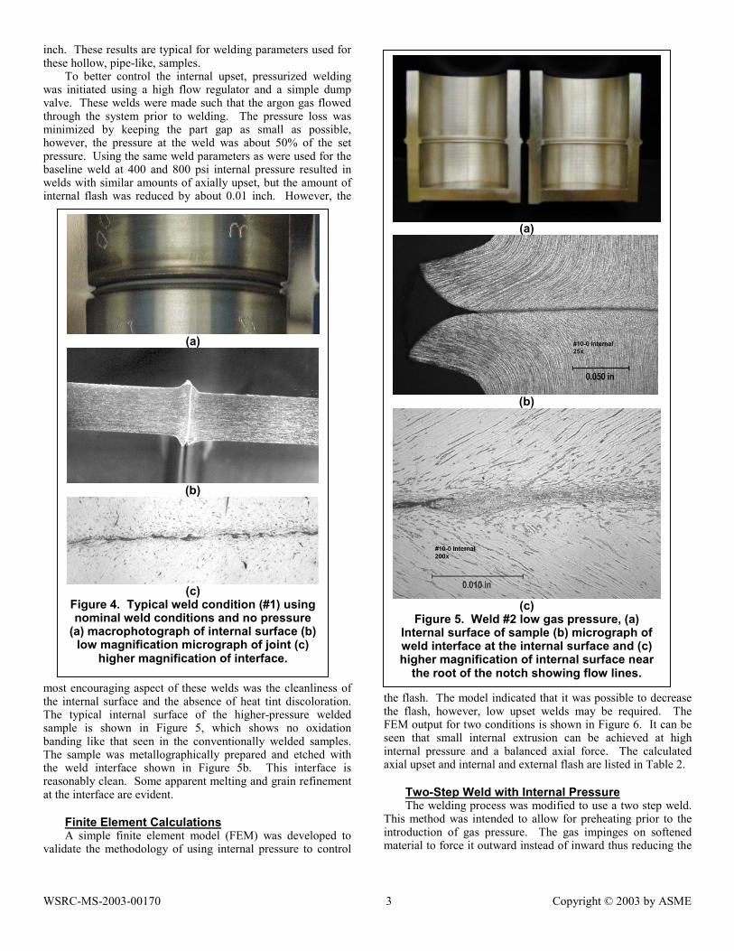
To better control the internal upset, pressurized weldingwas initiated using a high flow regulator and a simple dumpvalve. These welds were made such that the argon gas flowedthrough the system prior to welding. The pressure loss wasminimized by keeping the part gap as small as possible,however, the pressure at the weld was about 50% of the setpressure. Using the same weld parameters as were used for thebaseline weld at 400 and 800 psi internal pressure resulted inwelds with similar amounts of axially upset, but the amount ofinternal flash was reduced by about 0.01 inch. However, the
most encouraging aspect of these welds was the cleanliness ofthe internal surface and the absence of heat tint discoloration.The typical internal surface of the higher-pressure weldedsample is shown in Figure 5, which shows no oxidationbanding like that seen in the conventionally welded samples.The sample was metallographically prepared and etched withthe weld interface shown in Figure 5b. This interface isreasonably clean. Some apparent melting and grain refinementat the interface are evident.
Finite Element CalculationsA simple finite element model (FEM) was developed to
validate the methodology of using internal pressure to control
the flash. The model indicated that it was possible to decreasethe flash, however, low upset welds may be required. TheFEM output for two conditions is shown in Figure 6. It can beseen that small internal extrusion can be achieved at highinternal pressure and a balanced axial force. The calculatedaxial upset and internal and external flash are listed in Table 2.
Two-Step Weld with Internal PressureThe welding process was modified to use a two step weld.
This method was intended to allow for preheating prior to theintroduction of gas pressure. The gas impinges on softenedmaterial to force it outward instead of inward thus reducing the
(a)
(b)
(c)Figure 5. Weld #2 low gas pressure, (a)
Internal surface of sample (b) micrograph ofweld interface at the internal surface and (c)higher magnification of internal surface near
the root of the notch showing flow lines.
(a)
(b)
(c)Figure 4. Typical weld condition (#1) usingnominal weld conditions and no pressure
(a) macrophotograph of internal surface (b)low magnification micrograph of joint (c)
higher magnification of interface.

WSRC-MS-2003-00170 4 Copyright © 2003 by ASME
internal flash. Welding force was determined based on the FEmodel and previous tests. The applied axial force mustovercome the force exerted by the internal gas pressure. Inorder to decease the time needed to reach the final pressure anaccumulator was incorporated into the gas train as indicated inFigure 3.
Several samples were welded using this pressurizationsystem. Initially samples were welded at forces just largeenough to overcome the back force from the internal gaspressure. The welds formed using these parameters wereunacceptable having minimal bonding, less than 50% across theinterface. The upset was near zero, which is not unexpectedbased on prior tests. The internal surfaces were oxidized, muchlike the samples welded without internal gas pressure. Theinternal surface oxidized since the region of the weld washeated in laboratory air rather than under argon as occurred forthe continuously flowing gas. A typical sample that waswelded with increased pressure is shown in Fig. 7. Thebeneficial effects of internal gas pressure are not patentlyobvious. The bond-line is not visible in the EDM cut surface.The amount of upset is approximately 0.016 inch as indicatedin Table 1. Additional tests and continuing efforts will bereported in subsequent articles.
Flash Trap / MandrelsAn integral flash strap, machined step, or other feature, on
the internal surface often is used to contain internal flash. Theincorporation of these features must be anticipated during thepreliminary development stages to ensure that adequatematerial is provided in forgings or other raw materials used forthe component. For instance, additional stock on the internaldiameter from 0.05 to 0.150 inch may be necessary to divertflash and to prevent bending in stainless steel joints of the sizebeing developed. This internal flash trap may affect criticalinternal dimensions and internal volume.
Flash traps can be complex features with rings and groovesin addition to undercuts and various radii. These features maybe needed depending on whether the flash trap’s purpose iscontain and control flash or if it’s to change flow direction andavoid open notches on the internal surface.
To minimize the size of forgings and to reduce machiningcomplexity, a novel approach to integral flash traps has beentested internal mandrels. In this concept, the mandrels are of adifferent material that may be removed without adverselyaffecting the weld quality.
As a first approach, sacrificial glass, ceramic and metalrings as well as solid discs were tried. Both glass and ceramicrings lacked adequate impact strength to withstand the weldprocess. A machinable ceramic disk was subsequently tried. Itwithstood the welding forces but lacked adequate strength topreclude deformation during welding. A cross-section of theweld sample with the ceramic disc mandrel is shown in Fig. 8.It is apparent from this photograph that the upset material is notsymmetric as is typically observed for normal inertia welds.There appears to be more upset on the head stock piece, to theright in Fig. 8. In addition, the disk lacked the strength to avoidbeing deformed by the weld material. It is apparent that astiffer and stronger material is needed for this internal mandrelconcept.
A ferritic stainless steel mandrel was also evaluated. Theconcept behind using this material is that it would be lesscorrosion resistant than the austenitic material. Thus, it may bepossible to chemically etch the mandrel out of the vessel usingan appropriate chemical. A macrophotograph of the weldsample made with the ferritic SS mandrel is shown in Fig. 9a.The ring, which was originally placed flush against the tail-stock piece, has migrated towards the head-stock piece, i.e., to
(a)
(b)
Figure 6. FEM output for (a) low and (b) highinternal pressures.
Table 2. Calculated resutls from the FEM.
Force(lb)
Int. Pres.(psi)
Upset(in)
Int. Flash(in)
Ext. Flash(in)
10,000 2000 0.006 0.019 0.03413,600 2000 0.013 0.047 0.05515,800 4000 0.003 0.002 0.02418,100 4000 0.008 0.02 0.050
Figure 7. Sample #3 that was welded withincreased pressure.

WSRC-MS-2003-00170 5 Copyright © 2003 by ASME
the right. There is also some evidence of frictional heating onthe ring since it exhibits some discoloration on both the macroscale as well as on the microscale as shown in Fig. 9b. Themandrel apparently bonded to the flash as shown in themicrograph presented in Fig. 9c
DISCUSSIONTwo innovative methods of controlling flash in hollow
inertia welds are under development. These techniques areadvanced methods of controlling flash in inertia welds. Thetests reported in this document indicate that both pressure andmandrels have demonstrated utility for modifying the flash.Additional optimization of the techniques is required for
introduction of either method into a production setting.
SUMMARYPreliminary work discussed in this paper reveals that it
may be possible to control flash in inertia welds by using highpressure gas or expendable mandrels as alternatives toconventional flash traps. Additional testing and conceptydevelopment is needed.
ACKNOWLEDGMENTSThe authors would like to thank G. Chapman for operating
the welder, cutting samples, and assisting in other ways. Wewould also like to thank Z. Nelson, C. Foreman, V.Timmerman, J. Wilderman, and T. Curtis for metallographicsample preparation and N. Gupta for developing the FEMmodel. We would like acknowledge the guidance and supportof K. Hicken, M. Balmforth, and C. Pretzel of Sandia NationalLaboratories. This document was prepared in connection withwork done at Westinghouse Savannah River Company underContract No. DE-AC09-89SR18035 and DE-AC09-96SR18500with the U.S. Department of Energy.
REFERENCES1. H. B. Peacock, Method and device for frictional
welding, U.S. Patent No. 5,154,340, Oct. 1992.2. A. S. Wadleigh, Inertia Welding Industrial Energy
Saver, National Defense Magazine, July-August 1978.3. Inertia Welding Application Principles, Interface
Welding.
(a)
(b)Figure 8. Sample #4 welded with machinable
ceramic disk mandrel (a) macrophotograph (b)microphotograph showing flash and disk
interaction.
(a)
(b)
(c)Figure 9. Sample 5 welded with metal ring (a)
macrophotograph (b) microphotograph showinginteraction with metal ring (c) higher magnification
of the ring vessel interface.