innovative element technology for installation in hydac
TRANSCRIPT
E 7
.221
.4/1
1.16
43
Innovative Element Technologyfor installation in HYDAC filters
- Quick Selection -
E 7
.221
.4/1
1.16
43
44
E 7
.221
.4/1
1.16
High Quality Element Technology for Hydraulic Oils and Lubricants
DesignAs the core of the filter, it is the filter element which performs the actual filtration and/or dewatering function in the housing. Elements consist of several pleated filtration and support layers which are placed as a cylinder around or inside the stabilizing support tube. These mesh packs are sealed by the end-caps. Depending on the type of filter, flow direction through the filter elements is from the outside to the inside, or from the inside to the outside. Depending on the filter material, the filter mesh pack is encased in an additional outer plastic wrap.
Innovation Stat-Free® technologyWith the new Stat-Free® filter elements, HYDAC has for the first time succeeded in combining excellent electrostatic characteristics with filtration performance. Unprecedented low charge generation in the filter element and in the fluid in the system is achieved with a new type of filter element mat and element design.
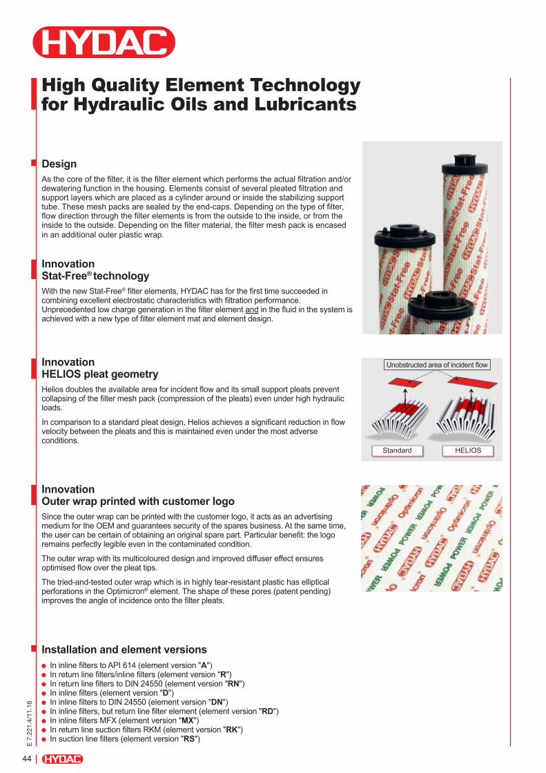
Innovation HELIOS pleat geometryHelios doubles the available area for incident flow and its small support pleats prevent collapsing of the filter mesh pack (compression of the pleats) even under high hydraulic loads.
In comparison to a standard pleat design, Helios achieves a significant reduction in flow velocity between the pleats and this is maintained even under the most adverse conditions.
Innovation Outer wrap printed with customer logo Since the outer wrap can be printed with the customer logo, it acts as an advertising medium for the OEM and guarantees security of the spares business. At the same time, the user can be certain of obtaining an original spare part. Particular benefit: the logo remains perfectly legible even in the contaminated condition.
The outer wrap with its multicoloured design and improved diffuser effect ensures optimised flow over the pleat tips.
The tried-and-tested outer wrap which is in highly tear-resistant plastic has elliptical perforations in the Optimicron® element. The shape of these pores (patent pending) improves the angle of incidence onto the filter pleats.
Installation and element versions In inline filters to API 614 (element version "A") In return line filters/inline filters (element version "R") In return line filters to DIN 24550 (element version "RN") In inline filters (element version "D") In inline filters to DIN 24550 (element version "DN") In inline filters, but return line filter element (element version "RD") In inline filters MFX (element version "MX") In return line suction filters RKM (element version "RK") In suction line filters (element version "RS")
Unobstructed area of incident flow
Standard HELIOS
E 7
.221
.4/1
1.16
45
Multipass-Filter Efficiency Data to ISO 16889
Dynamic Multipass Test = Hydraulic Load Cycle Test (HLCT)
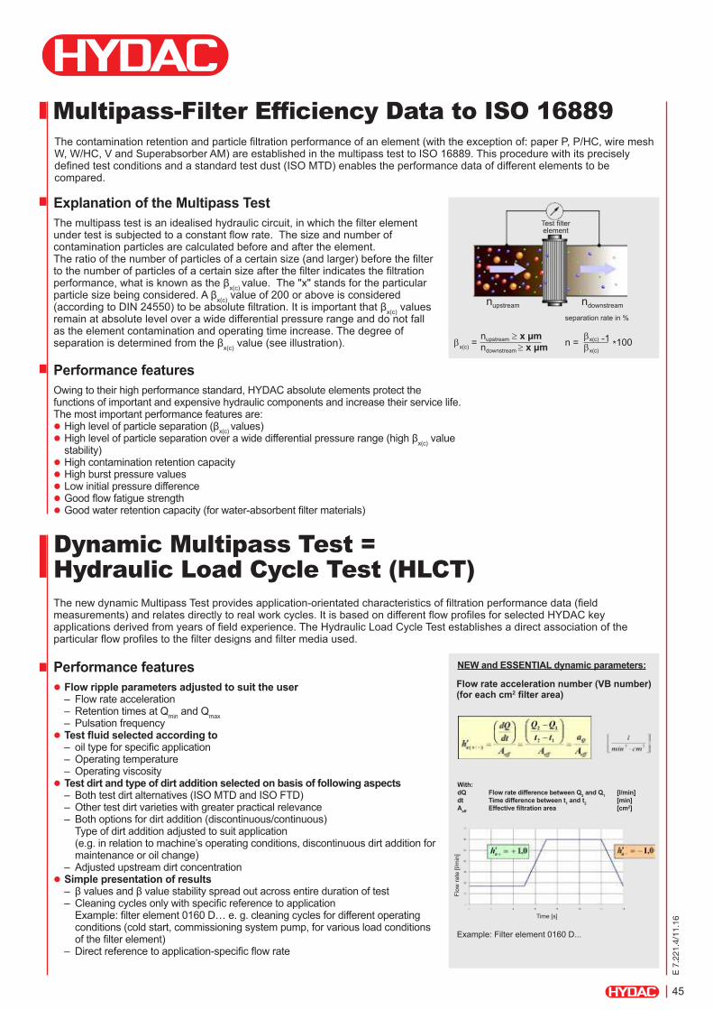
Explanation of the Multipass TestThe multipass test is an idealised hydraulic circuit, in which the filter element under test is subjected to a constant flow rate. The size and number of contamination particles are calculated before and after the element. The ratio of the number of particles of a certain size (and larger) before the filter to the number of particles of a certain size after the filter indicates the filtration performance, what is known as the βx(c) value. The "x" stands for the particular particle size being considered. A βx(c) value of 200 or above is considered (according to DIN 24550) to be absolute filtration. It is important that βx(c) values remain at absolute level over a wide differential pressure range and do not fall as the element contamination and operating time increase. The degree of separation is determined from the βx(c) value (see illustration).
The contamination retention and particle filtration performance of an element (with the exception of: paper P, P/HC, wire mesh W, W/HC, V and Superabsorber AM) are established in the multipass test to ISO 16889. This procedure with its precisely defined test conditions and a standard test dust (ISO MTD) enables the performance data of different elements to be compared.
The new dynamic Multipass Test provides application-orientated characteristics of filtration performance data (field measurements) and relates directly to real work cycles. It is based on different flow profiles for selected HYDAC key applications derived from years of field experience. The Hydraulic Load Cycle Test establishes a direct association of the particular flow profiles to the filter designs and filter media used.
Performance featuresOwing to their high performance standard, HYDAC absolute elements protect the functions of important and expensive hydraulic components and increase their service life. The most important performance features are:
High level of particle separation (βx(c) values) High level of particle separation over a wide differential pressure range (high βx(c) value stability)
High contamination retention capacity High burst pressure values Low initial pressure difference Good flow fatigue strength Good water retention capacity (for water-absorbent filter materials)
Performance features Flow ripple parameters adjusted to suit the user
– Flow rate acceleration – Retention times at Qmin and Qmax – Pulsation frequency
Test fluid selected according to – oil type for specific application – Operating temperature – Operating viscosity
Test dirt and type of dirt addition selected on basis of following aspects – Both test dirt alternatives (ISO MTD and ISO FTD) – Other test dirt varieties with greater practical relevance – Both options for dirt addition (discontinuous/continuous) Type of dirt addition adjusted to suit application (e.g. in relation to machine’s operating conditions, discontinuous dirt addition for maintenance or oil change)
– Adjusted upstream dirt concentration Simple presentation of results
– β values and β value stability spread out across entire duration of test – Cleaning cycles only with specific reference to application Example: filter element 0160 D… e. g. cleaning cycles for different operating conditions (cold start, commissioning system pump, for various load conditions of the filter element)
– Direct reference to application-specific flow rateExample: Filter element 0160 D...
Test filter element
βx(c) = nupstream ≥ x µm
ndownstream ≥ x µm n = βx(c) -1
*100 βx(c)
nupstream ndownstream
separation rate in %
Time [s]
Flow
rate
[l/m
in]
Flow rate acceleration number (VB number) (for each cm2 filter area)
With: dQ dt Aeff
Flow rate difference between Q2 and Q1 [l/min] Time difference between t1 and t2 [min] Effective filtration area [cm2]
NEW and ESSENTIAL dynamic parameters:

46
E 7
.221
.4/1
1.16
A large choice of filter elements.
Optimicron® Power Designation: ON/PO Filter material: plastic fibre, multi-layer support Filtration rating: 5, 10, 20 µm Collapse stability: 10 bar Flow direction: outside to inside. Plastic shell: yes Element version: A, R Element type: single-use element Brochure no.: 7.213../..
Optimicron® Pulse Designation: ON/PS, OH/PS Filter material: glass fibre, single-layer support Filtration rating: 3, 5, 10, 20 µm Collapse stability: 20 / 210 bar Flow direction: outside to inside. Plastic shell: yes Element version: D Element type: single-use element Brochure no.: 7.222../..
Optimicron® Pulp & Paper Designation: ON/PP Filter material: glass fibre, multi-layer support Filtration rating: 5 µm Collapse stability: 10 bar Flow direction: outside to inside. Plastic shell: yes Element version: R Element type: single-use element Brochure no.: 7.223../..
AFL
D
AFL
S
DF
DF.
.. M
P
DF.
..M A
D
F...
MH
A
DF.
..Q E
D
F...M
HE
DFD
K
DFD
KN
DFF
DFF
X
DFM
DFN
DFN
F
Optimicron® Power A A
Optimicron® Pulse D D D D D
Optimicron® Pulp & Paper
Optimicron® D D D D D D D D
Betamicron® D D D D D DN D D D DN DN
Mobilemicron®
Ecomicron®
Stainless steel wire mesh D D D D D DN D D DN DN
Paper
Metal fibre D D D D D D D
Aquamicron®
Aquamicron®/ Betamicron®
E 7
.221
.4/1
1.16
47
Betamicron®
Designation: BN4HC, BH4HC Filter material: glass fibre, multi-layer support Filtration rating: 3, 5, 6, 10, 20, 25 µm Collapse stability: 20 / 210 bar Flow direction: outside to inside. Plastic shell: yes Element version: D, DN, MX, R, RD, RN Element type: single-use element Brochure no.: 7.210../..
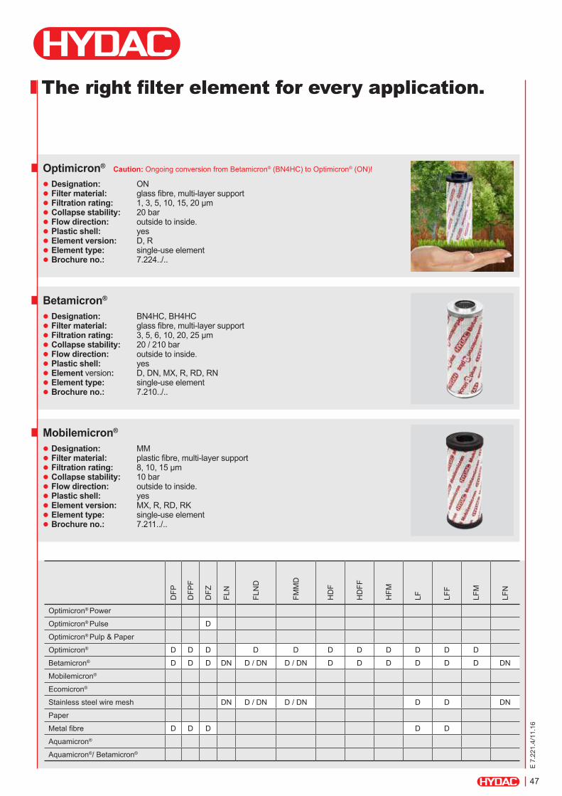
Optimicron®
Designation: ON Filter material: glass fibre, multi-layer support Filtration rating: 1, 3, 5, 10, 15, 20 µm Collapse stability: 20 bar Flow direction: outside to inside. Plastic shell: yes Element version: D, R Element type: single-use element Brochure no.: 7.224../..
Mobilemicron®
Designation: MM Filter material: plastic fibre, multi-layer support Filtration rating: 8, 10, 15 µm Collapse stability: 10 bar Flow direction: outside to inside. Plastic shell: yes Element version: MX, R, RD, RK Element type: single-use element Brochure no.: 7.211../..
DFP
DFP
F
DFZ
FLN
FLN
D
FMM
D
HD
F
HD
FF
HFM
LF LFF
LFM
LFN
Optimicron® Power
Optimicron® Pulse D
Optimicron® Pulp & Paper
Optimicron® D D D D D D D D D D D
Betamicron® D D D DN D / DN D / DN D D D D D D DN
Mobilemicron®
Ecomicron®
Stainless steel wire mesh DN D / DN D / DN D D DN
Paper
Metal fibre D D D D D
Aquamicron®
Aquamicron®/ Betamicron®
The right filter element for every application.
Caution: Ongoing conversion from Betamicron® (BN4HC) to Optimicron® (ON)!

48
E 7
.221
.4/1
1.16
Stainless steel wire mesh Designation: W, W/HC Filter material: stainless steel wire mesh Filtration rating: 25, 50, 100, 200 µm Collapse stability: 20 bar Flow direction: outside to inside (D, DN, R, RN) inside to outside (RS)
Plastic shell: no Element version: D, DN, R, RN, RS Element type: cleanable to some extent Brochure no.: 7.215../..
Stainless steel fibre Designation: V Filter material: metal fibre Filtration rating: 3, 5, 10, 20 µm Collapse stability: 210 bar Flow direction: outside to inside. Plastic shell: no Element version: D, R Element type: cleanable to some extent Brochure no.: 7.216../..
Ecomicron®
Designation: ECON2 Filter material: glass fibre, multi-layer support Filtration rating: 3, 5, 10, 20 µm Collapse stability: 10 bar Flow direction: outside to inside. Plastic shell: yes Element version: MX, R Element type: single-use element Brochure no.: 7.212../..
LFN
F
LPF
LPF.
..GG
A
LPF.
../-T
H
MD
F
MFM
MFM
...L
MFM
.../
-OIU
MFX
NF
NFD
RF
Optimicron® Power
Optimicron® Pulse
Optimicron® Pulp & Paper R R
Optimicron® D D D D D R R R
Betamicron® DN D RD RD D D D D MX R R R
Mobilemicron® RD RD MX
Ecomicron® MX R R
Stainless steel wire mesh DN D D R R R
Paper R R R
Metal fibre D R R R
Aquamicron® R R
Aquamicron®/ Betamicron® R R R
Better Quality, Performance and Efficiency.
E 7
.221
.4/1
1.16
49
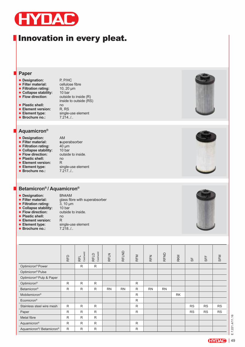
Aquamicron®
Designation: AM Filter material: superabsorber Filtration rating: 40 µm Collapse stability: 10 bar Flow direction: outside to inside. Plastic shell: no Element version: R Element type: single-use element Brochure no.: 7.217../..
Betamicron® / Aquamicron®
Designation: BN4AM Filter material: glass fibre with superabsorber Filtration rating: 3, 10 µm Collapse stability: 10 bar Flow direction: outside to inside. Plastic shell: no Element version: R Element type: single-use element Brochure no.: 7.218../..
Paper Designation: P, P/HC Filter material: cellulose fibre Filtration rating: 10, 20 µm Collapse stability: 10 bar Flow direction: outside to inside (R) inside to outside (RS)
Plastic shell: no Element version: R, RS Element type: single-use element Brochure no.: 7.214../..
RFD
RFL
C
ast/w
eld
RFL
D
Cas
t/wel
d
RFL
N
RFL
ND
RFM
RFN
RFN
D
RKM
SF
SFF
SFM
Optimicron® Power R R
Optimicron® Pulse
Optimicron® Pulp & Paper
Optimicron® R R R R
Betamicron® R R R RN RN R RN RN
Mobilemicron® R RK
Ecomicron® R
Stainless steel wire mesh R R R R RS RS RS
Paper R R R R RS RS RS
Metal fibre R R R
Aquamicron® R R R R
Aquamicron®/ Betamicron® R R R R
Innovation in every pleat.
50
E 7
.221
.4/1
1.16
IndustriegebietD-66280 Sulzbach/SaarGermanyTel.: +49 6897 509-01Fax: +49 6897 509-577e-mail: [email protected]: www.hydac.com
NOTICEThe information in this brochure relates to the operating conditions and applications described.For applications or operating conditions not described, please contact the relevant technical department. For applications or operating conditions not described please contact the relevant technical department.All technical details are subject to change without notice.
HYDAC FILTERTECHNIK GMBH
Bypass valve curves
∆p [b
ar]
Q [l/min]
30
∆p [b
ar]
Q [l/min]
60, 90, 110, 140, 150
∆p [b
ar]
Q [l/min]
75, 160, 165, 185, 240, 280
∆p [b
ar]
Q [l/min]
210, 270, 330, 500, 750
∆p [b
ar]
Q [l/min]
660, 850, 1700
∆p [b
ar]
Q [l/min]
950, 1300, 2600
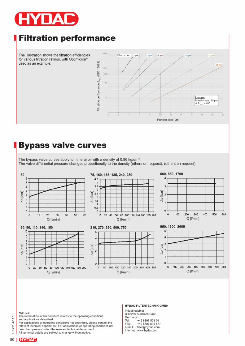
The bypass valve curves apply to mineral oil with a density of 0.86 kg/dm³. The valve differential pressure changes proportionally to the density (others on request). (others on request)
Filtration performance
The illustration shows the filtration efficiencies for various filtration ratings, with Optimicron®
used as an example:
Filtr
atio
n pe
rform
ance
βx(
C) (
ISO
168
89)
Particle size [µm]
Example: Filtration rate: 10 µm ß10 (c) = 400
Filtration rate:

E 7.
017.
2/11
.16
[Geben Sie Text ein]
Innovative Element Technology
Stat-Free®
51
E 7.
017.
2/11
.16
1. Introduction
The use of modern environmentally-friendly hy-draulic and lubrication oils, together with the trend towards ever more compact systems and finer filtra-tion, has in the past few years exacerbated the prob-lem of electrostatic charge and discharge. As a re-sult, the components integrated into the system be-come severely restricted in their function or are even damaged. Electrostatic discharges destroy filter ele-ments, damage valves and sensors and can even cause explosions in the hydraulic tank. In addition, they accelerate oil ageing.
To ensure that the whole system operates eco-nomically and without risk, it is essential to use filter systems which are capable of absorbing oil ageing products and which can prevent dangerous electro-static discharges from occurring. Unscheduled and costly oil changes can be avoided by using this sys-tem of filters.
We have recognized the long-term problem of
electrostatic discharge and with our innovative Stat-Free® series of elements have developed an effec-tive solution to the occurrence of charging and dis-charging in the hydraulic and lube circuit.
With findings drawn from the specifically designed Electrostatic Test Rig which has been verified by TÜV as well as numerous field tests, we have been able to create an element technology which inhibits the phenomenon of electrostatic discharge in the filter element as well as significantly reducing the charge in the oil.
In the following pages, the principles and conse-
quences of electrostatic charge and discharge in the hydraulic circuit are examined more closely and the advantages of the new Stat-Free® element technolo-gy are demonstrated.
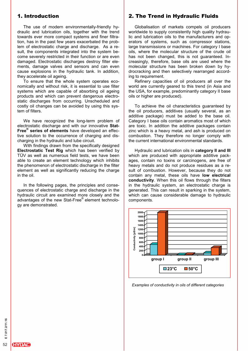
2. The Trend in Hydraulic Fluids
Globalisation of markets compels oil producers worldwide to supply consistently high quality hydrau-lic and lubrication oils to the manufacturers and op-erators of systems, such as compressor stations, large transmissions or machines. For category I base oils, where the molecular structure of the crude oil has not been changed, this is not guaranteed. In-creasingly, therefore, base oils are used where the molecular structure has been broken down by hy-drocracking and then selectively rearranged accord-ing to requirement.
Refinery capacities of oil producers all over the world are currently geared to this trend (in Asia and the USA, for example, predominantly category II base oils or higher are produced).
To achieve the oil characteristics guaranteed by
the oil producers, additives (usually several, as an additive package) must be added to the base oil. Category I base oils contain aromatics most of which are toxic. In addition the additive packages contain zinc which is a heavy metal, and ash is produced on combustion. They therefore no longer comply with the current international environmental standards.
Hydraulic and lubrication oils in category II and III
which are produced with appropriate additive pack-ages, contain no toxins or carcinogens, are free of heavy metals and do not produce residues as a re-sult of combustion. However, because they do not contain any metal, these oils have low electrical conductivity. When this oil flows through the filters in the hydraulic system, an electrostatic charge is generated. This can result in sparking in the system, which can cause considerable damage to hydraulic components.
Examples of conductivity in oils of different categories
0200400600800
100012001400160018002000
Con
duct
ivity
[pS/
m]
group I group II group III
23°C 50°C
52
E 7.
017.
2/11
.16

3. Theoretical Principles
3.1 Electrostatic charging of solid par-ticles
Every substance or material has a certain electron work function, i.e. the tendency to accept or release electrons. If two substances which have different electron work functions are then brought together (distance < 10-9m) at the same temperature, then at the point of interface, electrons are transferred from the material with low work function to the material with higher work function. An electrical double layer is produced with a certain charge Q. There does not have to be any friction between the two materials. Friction merely reduces the distance between the substances involved.
If the two materials are separated and the dis-
tance between them is therefore increased, the ca-pacitance is reduced and the potential difference (= voltage) is increased. Both materials are electrostati-cally charged.
The amount of charge is dependent on the speed
of separation, amongst other things. If separated slowly, charge can be equalized over the last point of contact. The faster the separation occurs, the higher will be the charge.
If the voltage generated exceeds the specific limit of dielectric strength (in air approx. 3 kV/mm), there will be a sudden equalization of voltage which is usu-ally in the form of discharge sparking.
3.2 Charging of fluids In fluid/solid systems as is the case in hydraulic
systems (filter medium/oil) a double charging layer is also formed here at the phase boundary, as shown in the following diagram. Near the boundary, this dou-ble layer consists of a linked layer of charge carriers (in this case positively charged). In the oil there is a diffuse layer of opposing (negative) charge carriers.
When the fluid then flows, the charge is carried downstream and creates a difference in potential. The faster the fluid is flowing, the higher the potential difference will be. If the voltage exceeds the dielectric strength of the oil, it will discharge in the form of sparking.
The precondition for charge generation is that the
fluid has a sufficiently low conductivity, otherwise the charges of the diffuse layer can flow back and can be equalized.
hydraulic fluid
- -
-
- -
-
-
-
-
-
- + + + + + + + + + + + + +
flow
sparking
filter media
filter media hydraulic fluid
-
-
-
- -
-
-
-
-
-
-
negative charge
positive charge + + + + + + + + + + + + +
2
1
a < 1 nm
double layer
electron migration
1
2
Development of the double layer
Separation of the two materials
Distribution of charge in fluid/solid systems
Sparking
53
E 7.
017.
2/11
.16
3.3 Main factors The main factors influencing the electrostatic
behaviour in hydraulic systems:
Electric conductivity The lower the conductivity, the higher the charge
Filter medium Different materials produce different charges depending on the electron work function
Temperature In general the charge falls as the temperature rises
Flow velocity The higher the flow velocity, the higher the charge
Contamination Conductive particles or water increase the con-ductivity of the fluid which results in a lower charge
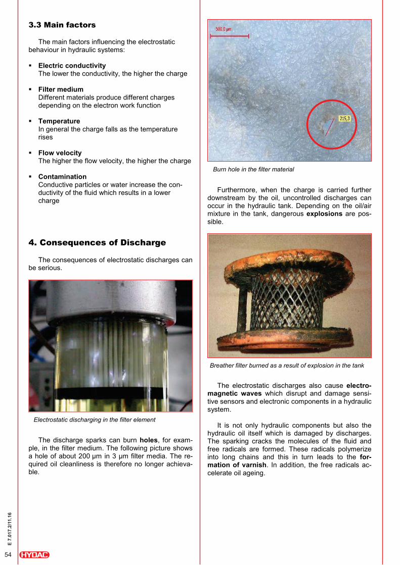
4. Consequences of Discharge The consequences of electrostatic discharges can
be serious.
The discharge sparks can burn holes, for exam-
ple, in the filter medium. The following picture shows a hole of about 200 µm in 3 µm filter media. The re-quired oil cleanliness is therefore no longer achieva-ble.
Furthermore, when the charge is carried further
downstream by the oil, uncontrolled discharges can occur in the hydraulic tank. Depending on the oil/air mixture in the tank, dangerous explosions are pos-sible.
The electrostatic discharges also cause electro-
magnetic waves which disrupt and damage sensi-tive sensors and electronic components in a hydraulic system.
It is not only hydraulic components but also the
hydraulic oil itself which is damaged by discharges. The sparking cracks the molecules of the fluid and free radicals are formed. These radicals polymerize into long chains and this in turn leads to the for-mation of varnish. In addition, the free radicals ac-celerate oil ageing.
Breather filter burned as a result of explosion in the tank
Burn hole in the filter material
Electrostatic discharging in the filter element
54
E 7.
017.
2/11
.16
5. Measuring Equipment
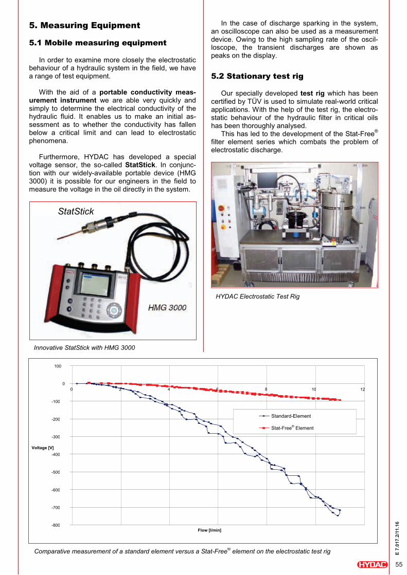
5.1 Mobile measuring equipment In order to examine more closely the electrostatic
behaviour of a hydraulic system in the field, we have a range of test equipment.
With the aid of a portable conductivity meas-
urement instrument we are able very quickly and simply to determine the electrical conductivity of the hydraulic fluid. It enables us to make an initial as-sessment as to whether the conductivity has fallen below a critical limit and can lead to electrostatic phenomena.
Furthermore, HYDAC has developed a special
voltage sensor, the so-called StatStick. In conjunc-tion with our widely-available portable device (HMG 3000) it is possible for our engineers in the field to measure the voltage in the oil directly in the system.
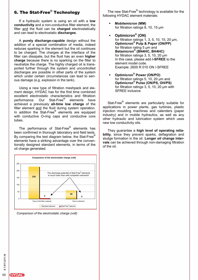
In the case of discharge sparking in the system, an oscilloscope can also be used as a measurement device. Owing to the high sampling rate of the oscil-loscope, the transient discharges are shown as peaks on the display. 5.2 Stationary test rig
Our specially developed test rig which has been certified by TÜV is used to simulate real-world critical applications. With the help of the test rig, the electro-static behaviour of the hydraulic filter in critical oils has been thoroughly analysed.
This has led to the development of the Stat-Free® filter element series which combats the problem of electrostatic discharge.
StatStick
Innovative StatStick with HMG 3000
HYDAC Electrostatic Test Rig
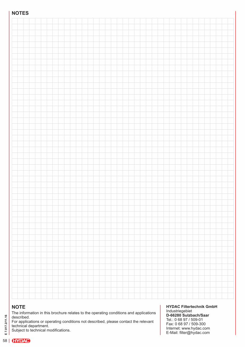
Comparative measurement of a standard element versus a Stat-Free® element on the electrostatic test rig
-800
-700
-600
-500
-400
-300
-200
-100
0
100
0 2 4 6 8 10
12
Flow [l/min]
Voltage [V]
Standard-Element Stat-Free® Element
55
E 7.
017.
2/11
.16
6. The Stat-Free® Technology If a hydraulic system is using an oil with a low
conductivity and a non-conductive filter element, the filter and the fluid can be charged electrostatically and can lead to electrostatic discharges.
A purely discharge-capable design without the
addition of a special combination of media, indeed reduces sparking in the element but the oil continues to be charged. The charges at the interface of the filter can dissipate, but the fluid has an even higher charge because there is no sparking on the filter to neutralize the charge. The highly charged oil is trans-ported further through the system and uncontrolled discharges are possible in other parts of the system which under certain circumstances can lead to seri-ous damage (e.g. explosion in the tank).
Using a new type of filtration meshpack and ele-
ment design, HYDAC has for the first time combined excellent electrostatic characteristics and filtratioin performance. Our Stat-Free® elements have achieved a previously all-time low charge of the filter element and the fluid during system operation. In addition the Stat-Free® elements are equipped with conductive O-ring caps and conductive core tubes.
The performance of Stat-Free® elements has
been confirmed in thorough laboratory and field tests. By comparing the test diagram below, the Stat-Free® elements have a striking advantage over the conven-tionally designed standard elements, in terms of the oil charge generated.
The new Stat-Free® technology is available for the following HYDAC element materials:
Mobilemicron (MM)
for filtration ratings 8, 10, 15 µm Optimicron® (ON)
for filtration ratings 1, 3, 5, 10, 15, 20 µm, Optimicron® Pulp & Paper (ON/PP) for filtration rating 5 µm and Betamicron® (BN4HC, BH4HC) for filtration ratings 3, 5, 10, 20 µm In this case, please add /-SFREE to the element model code. Example: 2600 R 010 ON /-SFREE
Optimicron® Power (ON/PO)
for filtration ratings 5, 10, 20 µm and Optimicron® Pulse (ON/PS, OH/PS) for filtration ratings 3, 5, 10, 20 µm with SFREE inclusive
Stat-Free® elements are particularly suitable for
applications in power plants, gas turbines, plastic injection moulding machines and calenders (paper industry) and in mobile hydraulics, as well as any other hydraulic and lubrication system which uses new low conductivity oils.
They guarantee a high level of operating relia-
bility, since they prevent sparks, deflagration and sludge formation in the oil. Longer oil change inter-vals can be achieved through non-damaging filtration of the oil.
Comparison of the electrostatic charge (volt)
4 0
230
60 0
50
100
150
200
250
Test on flat filter material Test on element Standard element Stat-Free® element
The discharge potential of Stat-Free® elements is much lower than with competitor elements!
Comparison of the electrostatic charge (volt)
56
E 7.
017.
2/11
.16

7. Real-World Example and Reference HYDAC became aware of the possibility of explo-
sions in the hydraulic tank of a large hydraulic system after breather filters were burned out. The filters con-cerned were competitor's filters which were not opti-mized for electrostatic charging. Measurements made on site using the StatStick revealed voltage peaks of up to 17,000 Volt and dangerous discharge sparks in the tank. Once retro-fitted with Stat-Free® elements, no further discharges could be detected and the voltage was just 2-3 Volt.
A number of established companies in sectors
such as turbine lubrication, presses, plastic injection moulding machines and mobile hydraulics have al-ready named HYDAC as a reference with regard to finding a solution to the problem of electrostatic dis-charge, as indicated by the following quotation:
"Due to numerous, frequently recurring difficulties on actual systems, we urgently recommend using filter cartridges which inhibit electrostatic charging in oils
with low electrical conductivity. These filters are available from HYDAC under the same model
code, by adding "/-SFREE"."
Moreover, the functionality of the Stat-Free® filter elements has been analysed by DEKRA EXAM GmbH, the German specialist unit for explosion protection at the mining test facility (BVS). The efficiency of the elements was confirmed in the expert report 13EXAM 10666 BVS-BI by DEKRA EXAM GmbH, Explosion Protection Department. 8. Summary
The charge separation in low conductivity oils
results in electrostatic charging and discharging.
Electrostatic discharges can cause the following damage, amongst others:
- Explosions in the hydraulic tank - Accelerated oil ageing - Damage to the filter element - Destruction of electronic components - Damage to cooler units
A conductive design of filter element is not suffi-
cient to reduce oil charging.
HYDAC Stat-Free® elements ensure a very low charge in the filter element and the hydraulic fluid
Advantages:
High level of operating reliability because discharge sparking, deflagration and sludge formation in the oil is eliminated
Longer oil change intervals because filtration of the oil is non-damaging
Conclusion: These developments prove that at HYDAC we will always find a solution to a customer problem. We not only provide an efficient result, but we will see you through the whole diagnostic process, especially in challenging cases.
We look forward to hearing about your new
projects!
Voltage measurement using StatStick (above: competitor's standard element voltage peaks up to 17kV [scaling: 5kV]; below: Hydac Stat-Free® element 2-3V [scaling: 5V])
57
E 7.
017.
2/11
.16
NOTEThe information in this brochure relates to the operating conditions and applications described. For applications or operating conditions not described, please contact the relevant technical department. Subject to technical modifications.
HYDAC Filtertechnik GmbH Industriegebiet D-66280 Sulzbach/Saar Tel.: 0 68 97 / 509-01 Fax: 0 68 97 / 509-300 Internet: www.hydac.com E-Mail: [email protected]
NOTES
58
E 7.
017.
2/11
.16

Energy efficient filtration. Our contribution to sustainability.
E 7
.220
.2/1
1.16
59
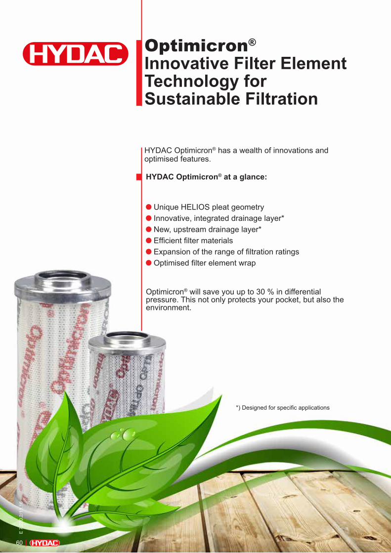
Optimicron®
Innovative Filter Element Technology for Sustainable Filtration
HYDAC Optimicron® has a wealth of innovations and optimised features.
HYDAC Optimicron® at a glance:
Unique HELIOS pleat geometry Innovative, integrated drainage layer* New, upstream drainage layer* Efficient filter materials Expansion of the range of filtration ratings Optimised filter element wrap
Optimicron® will save you up to 30 % in differential pressure. This not only protects your pocket, but also the environment.
*) Designed for specific applications
60
E 7
.220
.2/1
1.16

Optimicron®
Innovative Filter Element Technology for Sustainable Filtration
Optimicron®
Innovative Filter Element Technology for Sustainable Filtration
Resources are increasingly scarce, energy prices are rising and the environment is suffering. Energy efficiency is the key to counteracting this trend and to saving both costs and valuable resources.
HYDAC Optimicron® shows the way!
These innovative filter elements can make substantial savings on energy and costs for machine and system operators . The savings apply over the entire service life and the elements offer superior performance at the same time. The high energy efficiency of the new filter elements therefore reduces CO2 emissions.
Our contribution to sustainability!
Optimicron®
E 7
.220
.2/1
1.16
61

Optimicron® shows the wayEnergy and cost savings over the entire service life with superior performance at the same time.
Performance data
β-values for Optimicron®
∆p/Q Gradient coefficients in mbar / l/minOptimicron® D elements Optimicron® R elements
Size Filtration rating
1 µm 3 µm 5 µm 10 µm 15 µm 20 µm
0030 77.8 63.9 43.3 22.8 14.0 11.3
0035 50.2 21.3 17.1 13.7 10.0 7.44
0055 26.0 12.3 9.90 7.90 5.17 3.84
0060 53.5 26.0 18.3 12.1 9.78 6.32
0075 16.7 8.40 6.75 5.40 3.33 2.48
0095 13.2 6.74 5.40 4.33 2.62 1.92
0110 25.8 13.4 9.61 6.06 4.63 2.99
0140 19.9 11.5 7.39 4.38 3.54 2.29
0160 18.5 11.0 7.70 4.10 3.71 3.18
0240 11.5 6.90 5.34 3.19 2.44 2.10
0260 8.18 4.96 3.87 2.31 1.83 1.44
0280 5.54 3.37 2.74 1.49 1.36 1.17
0300 14.6 8.90 7.13 4.88 2.80 2.61
0330 8.23 4.19 3.37 2.46 1.55 1.22
0450 7.30 4.45 3.52 2.39 1.40 1.26
0500 5.05 2.57 2.07 1.23 0.949 0.747
0650 4.46 2.69 2.20 1.47 0.855 0.810
0660 3.78 1.93 1.56 0.93 0.710 0.562
0900 3.37 2.10 1.67 1.10 0.647 0.630
0990 2.51 1.280 1.031 0.613 0.472 0.372
1320 1.85 0.966 0.759 0.451 0.348 0.274
1500 1.64 0.968 0.704 0.480 0.360 0.284
Size Filtration rating
1 µm 3 µm 5 µm 10 µm 15 µm 20 µm
0030 89.8 68.4 43.9 26.8 16.8 14.7
0060 47.2 23.6 17.2 9.82 9.01 6.85
0075 25.6 19.4 13.4 7.31 4.80 4.40
0090 22.5 13.1 9.49 6.07 4.30 3.21
0110 22.3 13.1 8.87 5.40 4.26 3.24
0150 13.4 7.80 5.65 3.61 2.55 1.91
0160 16.0 8.00 5.68 3.22 2.69 2.32
0165 14.1 9.44 7.37 4.02 2.25 2.42
0185 10.4 7.44 5.74 2.93 1.65 1.41
0195 7.66 5.48 4.22 2.16 1.22 1.04
0210 5.66 3.28 2.55 1.53 1.00 0.88
0240 10.4 5.18 3.66 2.27 1.84 1.41
0270 3.66 2.12 1.65 0.993 0.649 0.568
0280 5.10 2.57 2.08 1.43 1.06 0.804
0330 8.09 3.72 2.73 1.48 1.28 1.02
0450 6.33 3.17 2.30 1.40 1.00 0.850
0500 5.27 2.60 1.90 1.09 0.835 0.685
0580 2.49 1.23 0.900 0.525 0.395 0.340
0600 2.35 1.23 1.10 0.613 0.416 0.340
0660 3.57 1.69 1.21 0.671 0.566 0.447
0750 2.11 1.12 0.924 0.529 0.335 0.322
0850 2.77 1.31 1.001 0.576 0.439 0.360
0950 2.39 1.03 0.793 0.476 0.379 0.311
1300 1.72 0.723 0.585 0.350 0.320 0.223
1700 1.35 0.640 0.527 0.281 0.252 0.176
2600 0.841 0.362 0.292 0.176 0.157 0.111
Filtr
atio
n pe
rform
ance
βx(
C) (
ISO
168
89)
Particle size [µm]
Example: Filtration rate: 10 µm ß10 (c) = 400
Filtration rate:
62
E 7
.220
.2/1
1.16
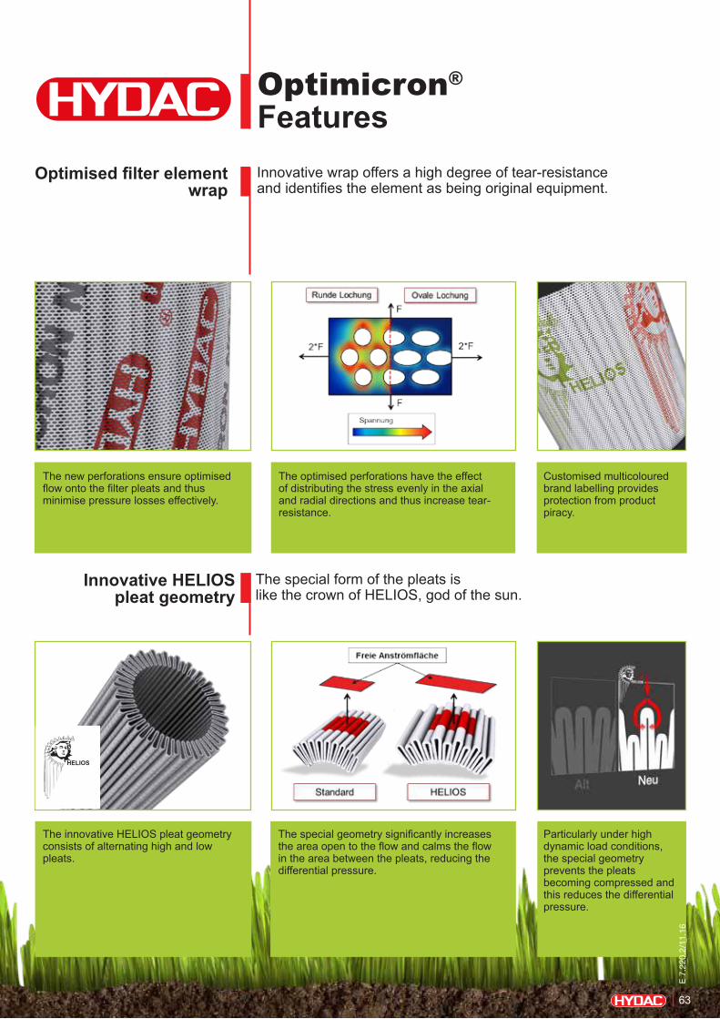
Optimicron® FeaturesInnovative wrap offers a high degree of tear-resistance and identifies the element as being original equipment.
The special form of the pleats is like the crown of HELIOS, god of the sun.
Optimised filter element wrap
Innovative HELIOS pleat geometry
HELIOS
Particularly under high dynamic load conditions, the special geometry prevents the pleats becoming compressed and this reduces the differential pressure.
The special geometry significantly increases the area open to the flow and calms the flow in the area between the pleats, reducing the differential pressure.
The innovative HELIOS pleat geometry consists of alternating high and low pleats.
The new perforations ensure optimised flow onto the filter pleats and thus minimise pressure losses effectively.
The optimised perforations have the effect of distributing the stress evenly in the axial and radial directions and thus increase tear-resistance.
Customised multicoloured brand labelling provides protection from product piracy.
E 7
.220
.2/1
1.16
63
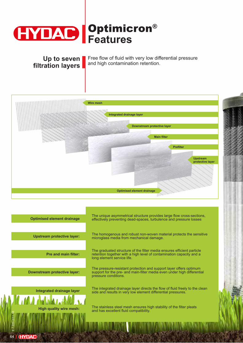
Optimicron® FeaturesFree flow of fluid with very low differential pressure and high contamination retention.
Up to seven filtration layers
Optimised element drainage
High quality wire mesh:
Integrated drainage layer
Downstream protective layer:
Pre and main filter:
Upstream protective layer:
The unique asymmetrical structure provides large flow cross-sections, effectively preventing dead-spaces, turbulence and pressure losses
The homogenous and robust non-woven material protects the sensitive microglass media from mechanical damage.
The graduated structure of the filter media ensures efficient particle retention together with a high level of contamination capacity and a long element service life.
The pressure-resistant protection and support layer offers optimum support for the pre- and main-filter media even under high differential pressure conditions.
The integrated drainage layer directs the flow of fluid freely to the clean side and results in very low element differential pressures.
The stainless steel mesh ensures high stability of the filter pleats and has excellent fluid compatibility.
Wire mesh
Upstream protective layer
Prefilter
Downstream protective layer
Main filter
Integrated drainage layer
Optimised element drainage
Protects the environment and
your pocket
64
E 7
.220
.2/1
1.16
Optimicron® Features
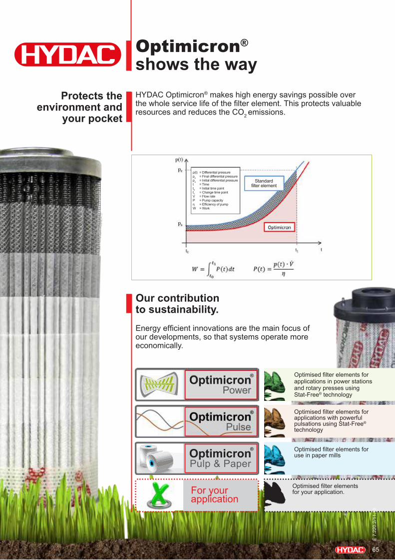
Optimicron® shows the wayHYDAC Optimicron® makes high energy savings possible over the whole service life of the filter element. This protects valuable resources and reduces the CO2 emissions.
Protects the environment and
your pocket
Our contribution to sustainability.Energy efficient innovations are the main focus of our developments, so that systems operate more economically.
OptimicronPulp & Paper
®
Optimised filter elements for applications in power stations and rotary presses using Stat-Free® technology
Optimised filter elements for applications with powerful pulsations using Stat-Free® technology
Optimised filter elements for use in paper mills
Optimised filter elements for your application.For your
application
p(t) = Differential pressure pe = Final differential pressure pa = Initial differential pressure t = Time t0 = Initial time point t1 = Change time point V = Flow rate P = Pump capacity η = Efficiency of pump W = Work
Standard filter element
E 7
.220
.2/1
1.16
65
NOTEThe information in this brochure relates to the operating conditions and applications described. For applications and operating conditions not described, please contact the proper HYDAC department. All technical details are subject to change without notice.
HYDAC Filtertechnik GmbH Industriegebiet D-66280 Sulzbach/Saar Tel.: 0 68 97 / 509-01 Fax: 0 68 97 / 509-300 Internet: www.hydac.com E-Mail: [email protected]
NOTES
66
E 7
.220
.2/1
1.16
67
E 7.
213.
2/11
.16
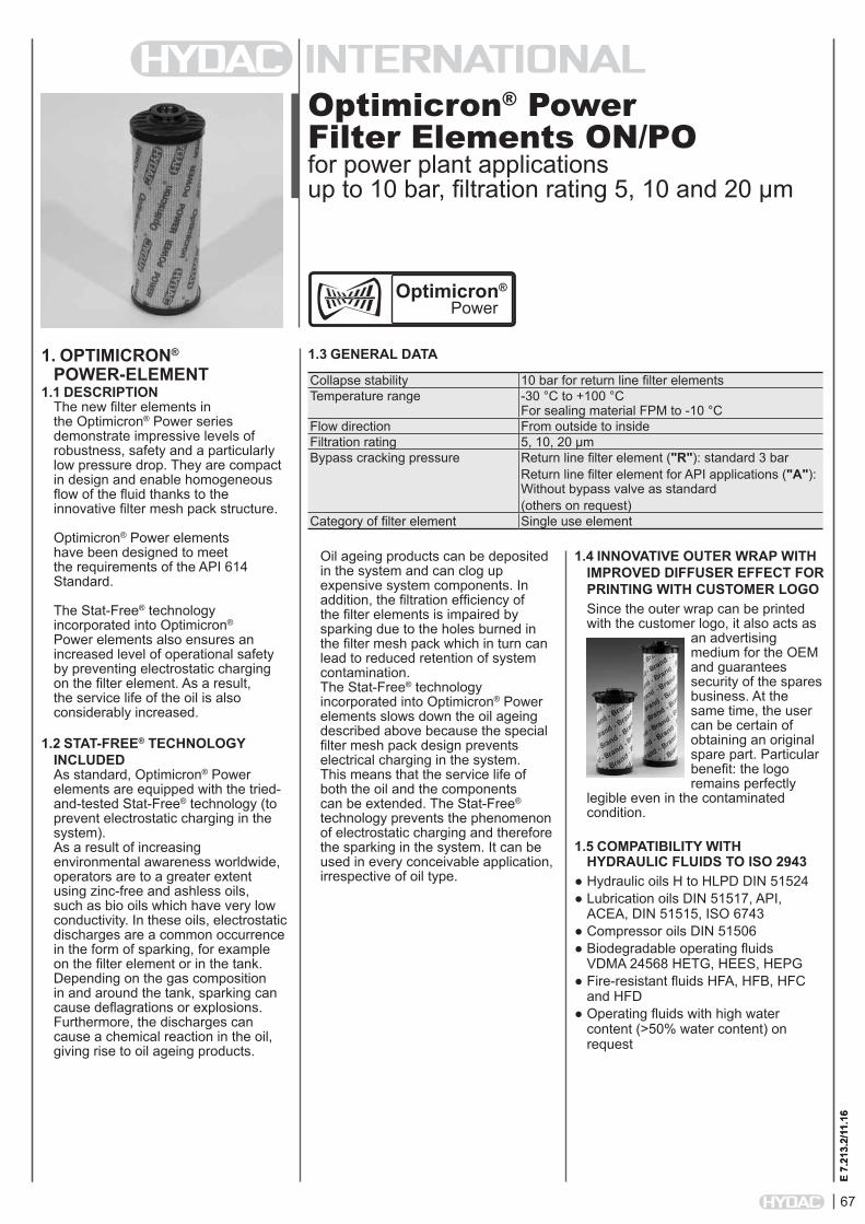
Optimicron® Power Filter Elements ON/POfor power plant applications up to 10 bar, filtration rating 5, 10 and 20 µm
1. OPTIMICRON® POWER-ELEMENT
1.1 DESCRIPTIONThe new filter elements in the Optimicron® Power series demonstrate impressive levels of robustness, safety and a particularly low pressure drop. They are compact in design and enable homogeneous flow of the fluid thanks to the innovative filter mesh pack structure.
Optimicron® Power elements have been designed to meet the requirements of the API 614 Standard.
The Stat-Free® technology incorporated into Optimicron® Power elements also ensures an increased level of operational safety by preventing electrostatic charging on the filter element. As a result, the service life of the oil is also considerably increased.
1.2 STAT-FREE® TECHNOLOGY INCLUDEDAs standard, Optimicron® Power elements are equipped with the tried-and-tested Stat-Free® technology (to prevent electrostatic charging in the system).As a result of increasing environmental awareness worldwide, operators are to a greater extent using zinc-free and ashless oils, such as bio oils which have very low conductivity. In these oils, electrostatic discharges are a common occurrence in the form of sparking, for example on the filter element or in the tank. Depending on the gas composition in and around the tank, sparking can cause deflagrations or explosions. Furthermore, the discharges can cause a chemical reaction in the oil, giving rise to oil ageing products.
1.3 GENERAL DATA
E 7.
213.
2/11
.16
Collapse stability 10 bar for return line filter elementsTemperature range -30 °C to +100 °C
For sealing material FPM to -10 °CFlow direction From outside to insideFiltration rating 5, 10, 20 µmBypass cracking pressure Return line filter element ("R"): standard 3 bar
Return line filter element for API applications ("A"): Without bypass valve as standard(others on request)
Category of filter element Single use element
1.4 INNOVATIVE OUTER WRAP WITH IMPROVED DIFFUSER EFFECT FOR PRINTING WITH CUSTOMER LOGOSince the outer wrap can be printed with the customer logo, it also acts as
an advertising medium for the OEM and guarantees security of the spares business. At the same time, the user can be certain of obtaining an original spare part. Particular benefit: the logo remains perfectly
legible even in the contaminated condition.
1.5 COMPATIBILITY WITH HYDRAULIC FLUIDS TO ISO 2943
● Hydraulic oils H to HLPD DIN 51524● Lubrication oils DIN 51517, API,
ACEA, DIN 51515, ISO 6743● Compressor oils DIN 51506● Biodegradable operating fluids
VDMA 24568 HETG, HEES, HEPG● Fire-resistant fluids HFA, HFB, HFC
and HFD ● Operating fluids with high water
content (>50% water content) on request
Oil ageing products can be deposited in the system and can clog up expensive system components. In addition, the filtration efficiency of the filter elements is impaired by sparking due to the holes burned in the filter mesh pack which in turn can lead to reduced retention of system contamination. The Stat-Free® technology incorporated into Optimicron® Power elements slows down the oil ageing described above because the special filter mesh pack design prevents electrical charging in the system. This means that the service life of both the oil and the components can be extended. The Stat-Free® technology prevents the phenomenon of electrostatic charging and therefore the sparking in the system. It can be used in every conceivable application, irrespective of oil type.
Optimicron®
Power

68
E 7.
213.
2/11
.16
2. MODEL CODE
0660 R 010 ON/PO /-KBSize 0110, 0240, 0330, 0500, 0660, 0850, 0950, 1300, 1700, 2600, 2700Type R Return line filter elementFiltration rating in µm 005, 010, 020Filter material of element ON/PO Optimicron® Power, collapse stability up to 10 barSupplementary details V FPM (Viton) seal KB without bypass valve
2.1 MODEL CODE FOR STANDARD RETURN LINE FILTER ELEMENTS(Can be used in the following filters: RFL, RFLD)
0880 A 010 ON/PO /-VSize 0110, 0120, 0230, 0240, 0330, 0500, 0540, 0880, 1400, 2700Type A Filter elements to API standardsFiltration rating in µm 010Filter material of element ON/PO Optimicron® Power, collapse stability up to 10 barSupplementary details V FPM (Viton) seal
2.2 MODEL CODE FOR RETURN LINE FILTER ELEMENTS IN AFLD AND ALFS FILTERS
3. FILTER CALCULATION / SIZINGThe total pressure drop of a filter at a certain flow rate Q is the sum of the housing ∆p and the element ∆p and is calculated as follows:∆ptotal = ∆phousing + ∆pelement
∆phousing = see housing curve in the relevant filter brochure
∆pelement = Q • SK* • viscosity 1000 30 (*see point 4.1)
4. ELEMENT CHARACTERISTICS
4.1 GRADIENT COEFFICIENTS FOR FILTER ELEMENTSThe gradient coefficients in mbar/(l/min) apply to mineral oils with a kinematic viscosity of 30 mm²/s. The pressure drop changes proportionally to the change in viscosity.
Return line filter element "R"...ON/POSize 5 µm 10 µm 20 µm0110 3.63 3.08 2.030240 1.32 1.12 0.720330 0.81 0.69 0.440500 0.53 0.45 0.290660 0.35 0.30 0.190850 0.28 0.24 0.160950 0.25 0.21 0.141300 0.18 0.15 0.101700 0.13 0.11 0.072600 0.08 0.07 0.052700 0.08 0.07 0.05
Return line filter element "A"...ON/POSize 10 µm0110 3.080120 1.370230 0.680240 1.120330 0.690500 0.450540 0.330880 0.141400 0.092700 0.07
For information on bypass valve curves, please see Filter Element (Quick Selection) brochure no.: E 7.221../..
NOTEThe information in this brochure relates to the operating conditions and applications described. For applications or operating conditions not described, please contact the relevant technical department. Subject to technical modifications.
HYDAC Filtertechnik GmbH Industriegebiet D-66280 Sulzbach/Saar Tel.: 0 68 97 / 509-01 Fax: 0 68 97 / 509-300 Internet: www.hydac.com E-Mail: [email protected]

69
E 7.
222.
2/11
.16
Optimicron® Pulse Filter Elements ON/PS / OH/PSfor applications with strong pulsationsup to 210 bar, filtration rating 3, 5, 10 and 20 µm
1. OPTIMICRON® PULSE ELEMENT
1.1 DESCRIPTIONThe new application-specific filter elements in the Optimicron® Pulse series are notable for their special fatigue strength in applications which are subject to extreme pulsations.
Pressure fluctuations in hydraulic systems can occur, for example, when cylinder pistons move or accumulators are charged. The frequency of pressure fluctuations varies considerably depending on the application. On injection moulding machines, the movement of the clamping unit causes large pressure fluctuations, often with an extremely high cycle rate. The new HYDAC Optimicron® Pulse filter element can withstand these dynamic stresses. Special flexible materials in the filter mesh pack provide the filter element with a high fatigue strength. Fatigue fractures in the filter mesh pack and penetration of contamination to the clean side are therefore prevented.
The innovative HELIOS pleat geometry ensures a free cross-sectional area even at high flow rates and as a result delivers a lower differential pressure.
Additionally, the Optimicron® Pulse filter element is fitted with the tried and tested Stat-Free® technology, which effectively prevents electrostatic discharges in the hydraulic system.
1.2 GENERAL DATA
E 7.
222.
2/11
.16
Collapse stability ON/PS: 20 bar OH/PS: 210 bar
Temperature range -30 °C to +100 °C For sealing material FPM to -10 °C
Flow direction From outside to insideFiltration rating 3, 5, 10, 20 µmBypass cracking pressure Pressure filter element ("D"):
Without bypass valve as standard (bypass valve on request)
Category of filter element Single use element
1.4 INNOVATIVE OUTER WRAP WITH INCREASED ROBUSTNESS AND IMPROVED DIFFUSER EFFECT FOR PRINTING WITH CUSTOMER LOGOSince the outer wrap can be printed with the customer logo, it also acts as
an advertising medium for the OEM and guarantees security of the spares business. At the same time, the user can be certain of obtaining an original spare part. Particular benefit: the logo remains perfectly
legible even in the contaminated condition.
1.5 COMPATIBILITY WITH HYDRAULIC FLUIDS TO ISO 2943
● Hydraulic oils H to HLPD DIN 51524● Lubrication oils DIN 51517, API,
ACEA, DIN 51515, ISO 6743● Compressor oils DIN 51506● Biodegradable operating fluids
VDMA 24568 HETG, HEES, HEPG● Fire-resistant fluids HFA, HFB, HFC
and HFD ● Operating fluids with high water
content (>50% water content) on request
1.3 STAT-FREE TECHNOLOGY INCLUDEDAs standard, Optimicron® Pulse elements are equipped with the tried-and-tested Stat-Free® technology (to prevent electrostatic charging in the system).As a result of increasing environmental awareness worldwide, operators are to a greater extent using zinc-free and ashless oils, such as bio oils which have very low conductivity. In these oils, electrostatic discharges are a common occurrence in the form of sparking, for example on the filter element or in the tank. Depending on the gas composition in and around the tank, sparking can cause deflagrations or explosions. Oil ageing products can be deposited in the system and can clog up expensive system components. In addition, the filtration efficiency of the filter elements is impaired by sparking due to the holes burned in the filter mesh pack which in turn can lead to reduced retention of system contamination. The Stat-Free® technology incorporated into Optimicron® Pulse elements slows down the oil ageing described above because the special filter mesh pack design prevents electrical charging in the system. This means that the service life of both the oil and the components can be extended. The Stat-Free® technology prevents the phenomenon of electrostatic charging and therefore the sparking in the system. It can be used in every conceivable application, irrespective of oil type.
Optimicron ® Pulse

70
E 7.
222.
2/11
.16
2. MODEL CODE
0660 D 010 ON/PS /-VSize 0030, 0060, 0110, 0140, 0160, 0240, 0260, 0280, 0330, 0500, 0660, 0990, 1320, 1500Type D Pressure filter elementFiltration rating in µm 003, 005, 010, 020Filter material of element ON/PS Optimicron® Pulse, collapse stability up to 20 bar OH/PS Optimicron® Pulse, collapse stability up to 210 barSupplementary details V FPM (Viton) seal
2.1 MODEL CODE FOR STANDARD PRESSURE FILTER ELEMENTS(For use in filters: LF, LFF, LPF, DF, DFF, DF…MHA, DF…MHE, DFZ)
3. FILTER CALCULATION / SIZINGThe total pressure drop of a filter at a certain flow rate Q is the sum of the housing ∆p and the element ∆p and is calculated as follows:∆ptotal = ∆phousing + ∆pelement
∆phousing = see housing curve in the relevant filter brochure
∆pelement = Q • SK* • viscosity 1000 30 (*see Point 4.1)
4. ELEMENT CHARACTERISTICS
4.1 GRADIENT COEFFICIENTS FOR FILTER ELEMENTSThe gradient coefficients in mbar/(l/min) apply to mineral oils with a kinematic viscosity of 30 mm²/s. The pressure drop changes proportionally to the change in viscosity.
Pressure filter element "D"...ON/PSSize 3 µm 5 µm 10 µm 20 µm0030 63.9 43.3 25.1 11.30035 23.6 19.0 16.3 9.30055 13.7 11.0 8.9 4.80060 28.9 20.4 14.5 7.90110 14.9 10.7 7.3 3.70140 12.8 8.2 5.3 2.90160 13.1 8.8 5.5 3.50240 8.2 6.1 4.3 2.30260 1.7 7.3 4.8 2.50280 4.0 3.1 2.0 1.30330 8.6 3.9 3.0 1.70500 3.0 2.4 1.5 1.10660 2.3 1.8 1.1 0.80990 2.0 1.2 0.7 0.51320 1.1 0.9 0.5 0.41500 1.1 0.9 0.5 0.4
Pressure filter element "D"...OH/PSSize 3 µm 5 µm 10 µm 20 µm0030 87.5 59.3 34.4 15.50035 32.3 26.0 22.3 12.70055 18.8 15.1 12.2 6.60060 39.6 28.0 19.9 10.80110 20.4 14.7 10.0 5.10140 17.5 11.2 7.2 4.00160 18.0 12.1 7.6 4.80240 11.2 8.4 5.9 3.20260 2.3 10.0 6.6 3.40280 5.5 4.3 2.8 1.80330 6.7 5.3 4.1 2.30500 4.1 3.3 2.1 1.50660 3.1 2.5 1.5 1.10990 2.0 1.6 1.0 0.71320 1.5 1.2 0.7 0.61500 1.5 1.2 0.7 0.6
For information on bypass valve curves, please see Filter Element (Quick Selection) brochure no.: E 7.221../..
NOTEThe information in this brochure relates to the operating conditions and applications described. For applications or operating conditions not described, please contact the relevant technical department. Subject to technical modifications.
HYDAC Filtertechnik GmbH Industriegebiet D-66280 Sulzbach/Saar Tel.: 0 68 97 / 509-01 Fax: 0 68 97 / 509-300 Internet: www.hydac.com E-Mail: [email protected]
71
E 7.
223.
2/11
.16
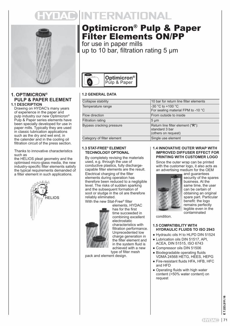
Optimicron® Pulp & Paper Filter Elements ON/PPfor use in paper millsup to 10 bar, filtration rating 5 µm
1. OPTIMICRON® PULP & PAPER ELEMENT
1.1 DESCRIPTIONDrawing on HYDAC's many years of experience in the paper and pulp industry our new Optimicron® Pulp & Paper series elements have been specially developed for use in paper mills. Typically they are used in classic lubrication applications such as the dry and wet end, in the calender and in the cooling oil filtration circuit of the press section.
Thanks to innovative characteristics such asthe HELIOS pleat geometry and the optimised micro-glass media, the new industry-specific filter elements satisfy the typical requirements demanded of a filter element in such applications.
1.2 GENERAL DATA
E 7.
223.
2/11
.16
Collapse stability 10 bar for return line filter elementsTemperature range -30 °C to +100 °C
For sealing material FPM to -10 °CFlow direction From outside to insideFiltration rating 5 µmBypass cracking pressure Return line filter element ("R"):
standard 3 bar (others on request)
Category of filter element Single use element
Optimicron®
Pulp & Paper
1.4 INNOVATIVE OUTER WRAP WITH IMPROVED DIFFUSER EFFECT FOR PRINTING WITH CUSTOMER LOGOSince the outer wrap can be printed with the customer logo, it also acts as an advertising medium for the OEM
and guarantees security of the spares business. At the same time, the user can be certain of obtaining an original spare part. Particular benefit: the logo remains perfectly legible even in the contaminated
condition.
1.5 COMPATIBILITY WITH HYDRAULIC FLUIDS TO ISO 2943
● Hydraulic oils H to HLPD DIN 51524● Lubrication oils DIN 51517, API,
ACEA, DIN 51515, ISO 6743● Compressor oils DIN 51506● Biodegradable operating fluids
VDMA 24568 HETG, HEES, HEPG● Fire-resistant fluids HFA, HFB, HFC
and HFD ● Operating fluids with high water
content (>50% water content) on request
1.3 STAT-FREE® ELEMENT TECHNOLOGY OPTIONALBy completely revising the materials used, e.g. through the use of conductive plastics, fully discharge-capable filter elements are the result. Electrical charging of the filter elements during operation has therefore been reduced to a negligible level. The risks of sudden sparking and the subsequent formation of soot or sludge in the oil are therefore reliably eliminated.With the new Stat-Free® filter
elements, HYDAC has for the first time succeeded in combining excellent electrostatic characteristics with filtration performance. Unprecedented low charge generation in the filter element and in the system fluid is achieved with a new
type of filter mesh pack and element design.

72
E 7.
223.
2/11
.16
2. MODEL CODE
1300 R 005 ON/PP /-KBSize 1300, 2600Type R Return line filter elementFiltration rating in µm 005Filter material of element ON/PP Optimicron® Pulp & Paper, collapse stability up to 10 barSupplementary details V FPM (Viton) seal KB without bypass valve SFREE Stat-Free® element technology
2.1 MODEL CODE FOR STANDARD RETURN LINE FILTER ELEMENTS(Can be used in filters: NF und NFD, starting at size 1340)
3. FILTER CALCULATION / SIZINGThe total pressure drop of a filter at a certain flow rate Q is the sum of the housing ∆p and the element ∆p and is calculated as follows:∆ptotal = ∆phousing + ∆pelement
∆phousing = see housing curve in the relevant filter brochure
∆pelement = Q • SK* • viscosity 1000 30 (*see Point 4.1)
4. ELEMENT CHARACTERISTICS
4.1 GRADIENT COEFFICIENTS FOR FILTER ELEMENTSThe gradient coefficients in mbar/(l/min) apply to mineral oils with a kinematic viscosity of 30 mm²/s. The pressure drop changes proportionally to the change in viscosity.
Return line filter element "R"...ON/PPSize 5 µm1300 1.002600 0.45
For information on bypass valve curves, please see Filter Element (Quick Selection) brochure no.: E 7.221../..
NOTEThe information in this brochure relates to the operating conditions and applications described. For applications or operating conditions not described, please contact the relevant technical department. Subject to technical modifications.
HYDAC Filtertechnik GmbH Industriegebiet D-66280 Sulzbach/Saar Tel.: 0 68 97 / 509-01 Fax: 0 68 97 / 509-300 Internet: www.hydac.com E-Mail: [email protected]
73
E 7.
224.
2/11
.16
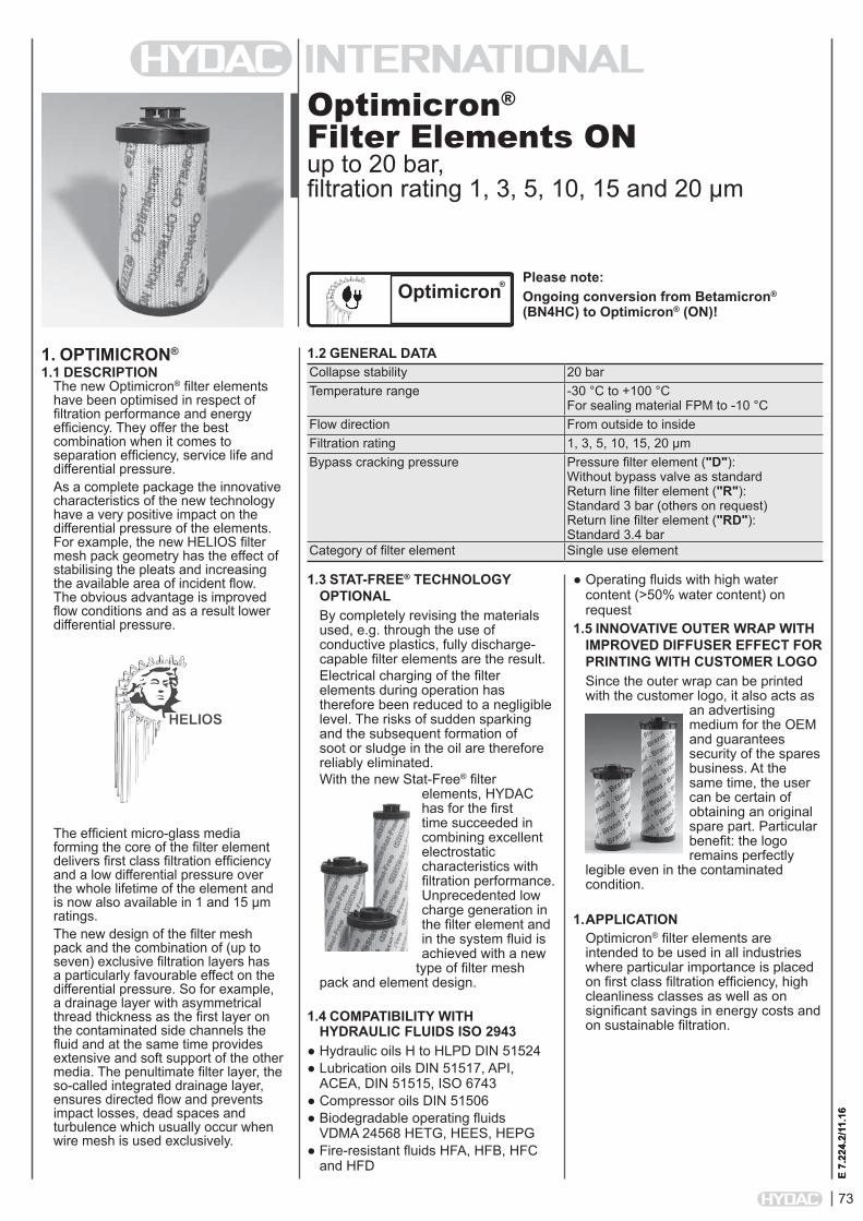
Optimicron® Filter Elements ONup to 20 bar, filtration rating 1, 3, 5, 10, 15 and 20 µm
1. OPTIMICRON®
1.1 DESCRIPTIONThe new Optimicron® filter elements have been optimised in respect of filtration performance and energy efficiency. They offer the best combination when it comes to separation efficiency, service life and differential pressure.As a complete package the innovative characteristics of the new technology have a very positive impact on the differential pressure of the elements. For example, the new HELIOS filter mesh pack geometry has the effect of stabilising the pleats and increasing the available area of incident flow. The obvious advantage is improved flow conditions and as a result lower differential pressure.
The efficient micro-glass media forming the core of the filter element delivers first class filtration efficiency and a low differential pressure over the whole lifetime of the element and is now also available in 1 and 15 µm ratings.The new design of the filter mesh pack and the combination of (up to seven) exclusive filtration layers has a particularly favourable effect on the differential pressure. So for example, a drainage layer with asymmetrical thread thickness as the first layer on the contaminated side channels the fluid and at the same time provides extensive and soft support of the other media. The penultimate filter layer, the so-called integrated drainage layer, ensures directed flow and prevents impact losses, dead spaces and turbulence which usually occur when wire mesh is used exclusively.
1.2 GENERAL DATA
E 7.
224.
2/11
.16
Collapse stability 20 barTemperature range -30 °C to +100 °C
For sealing material FPM to -10 °CFlow direction From outside to insideFiltration rating 1, 3, 5, 10, 15, 20 µmBypass cracking pressure Pressure filter element ("D"):
Without bypass valve as standard Return line filter element ("R"): Standard 3 bar (others on request) Return line filter element ("RD"): Standard 3.4 bar
Category of filter element Single use element
Please note:Ongoing conversion from Betamicron® (BN4HC) to Optimicron® (ON)!
Optimicron®
1.3 STAT-FREE® TECHNOLOGY OPTIONALBy completely revising the materials used, e.g. through the use of conductive plastics, fully discharge-capable filter elements are the result. Electrical charging of the filter elements during operation has therefore been reduced to a negligible level. The risks of sudden sparking and the subsequent formation of soot or sludge in the oil are therefore reliably eliminated.With the new Stat-Free® filter
elements, HYDAC has for the first time succeeded in combining excellent electrostatic characteristics with filtration performance. Unprecedented low charge generation in the filter element and in the system fluid is achieved with a new
type of filter mesh pack and element design.
1.4 COMPATIBILITY WITH HYDRAULIC FLUIDS ISO 2943
● Hydraulic oils H to HLPD DIN 51524● Lubrication oils DIN 51517, API,
ACEA, DIN 51515, ISO 6743● Compressor oils DIN 51506● Biodegradable operating fluids
VDMA 24568 HETG, HEES, HEPG● Fire-resistant fluids HFA, HFB, HFC
and HFD
● Operating fluids with high water content (>50% water content) on request
1.5 INNOVATIVE OUTER WRAP WITH IMPROVED DIFFUSER EFFECT FOR PRINTING WITH CUSTOMER LOGOSince the outer wrap can be printed with the customer logo, it also acts as
an advertising medium for the OEM and guarantees security of the spares business. At the same time, the user can be certain of obtaining an original spare part. Particular benefit: the logo remains perfectly
legible even in the contaminated condition.
1. APPLICATIONOptimicron® filter elements are intended to be used in all industries where particular importance is placed on first class filtration efficiency, high cleanliness classes as well as on significant savings in energy costs and on sustainable filtration.

74
E 7.
224.
2/11
.16
2. MODEL CODE
0660 D 010 ON /-VSize 0030, 0035, 0055, 0060, 0075, 0095, 0110, 0140, 0160, 0240, 0260, 0280, 0300, 0330, 0450, 0500, 0650, 0660, 0900, 0990, 1320, 1500Type D Pressure filter elementFiltration rating in µm 001, 003, 005, 010, 015, 020Filter material of element ON Collapse stability up to 20 barSupplementary details V FPM (Viton) seal SFREE Stat-Free® element technology
2.1 MODEL CODE FOR STANDARD PRESSURE FILTER ELEMENTS(Can be used in the following filters: LFM, MFM, MFM…/-OIU, MFM..L.., DFM, HFM, LPF, LF, LFF, MDF, HDF, HDFF, DF, DFF, DFFX, FLND, FMND, DFDK, DF…MHA, DF…MHE, DF…M A, DF…M P, DFZ, DF…Q E, DFP, DFPF)
0660 R 010 ON /-VSize 0030, 0060, 0075, 0090, 0110, 0150, 0160, 0165, 0185, 0195, 0210, 0240, 0260, 0270, 0280, 0330, 0450, 0500, 0580, 0600, 0660, 0750, 0850, 0950, 1300, 1700, 2600Type R Return line filter elementFiltration rating in µm 001, 003, 005, 010, 015, 020Filter material of element ON Collapse stability up to 20 barSupplementary details V FPM (Viton) seal KB without bypass valve SFREE Stat-Free® element technology
2.2 MODEL CODE FOR STANDARD RETURN LINE FILTER ELEMENTS(Can be used in the following filters: RFM, RF, RFD, RFL, RFLD, NF, NFD)
0241 RD 010 ON /-VSize 0161, 0241, 0261, 0281Type RD Return line filter element for pressure filtersFiltration rating in µm 001, 003, 005, 010, 015, 020Filter material of element ON Collapse stability up to 20 barSupplementary details V FPM (Viton) seal
2.3 MODEL CODE FOR RETURN LINE FILTER ELEMENTS IN PRESSURE FILTERS(Can be used in the following filters: LPF…/-TH, LPF…GGA)

75
E 7.
224.
2/11
.16
3. FILTER CALCULATION / SIZINGThe total pressure drop of a filter at a certain flow rate Q is the sum of the housing ∆p and the element ∆p and is calculated as follows:∆ptotal = ∆phousing + ∆pelement
∆phousing = see housing curve in the relevant filter brochure
∆pelement = Q • SK* • viscosity 1000 30 (*see Point 4.1)
4. ELEMENT CHARACTERISTICS4.1 GRADIENT COEFFICIENTS FOR FILTER ELEMENTS
The gradient coefficients in mbar/(l/min) apply to mineral oils with a kinematic viscosity of 30 mm²/s. The pressure drop changes proportionally to the change in viscosity.
Pressure filter element "D"...ONSize 1 µm 3 µm 5 µm 10 µm 15 µm 20 µm0030 77.8 63.9 43.3 22.8 14.0 11.30035 50.2 21.3 17.1 13.7 10.0 7.440055 26.0 12.3 9.90 7.90 5.17 3.840060 53.5 26.0 18.3 12.1 9.78 6.320075 16.7 8.40 6.75 5.40 3.33 2.480095 13.2 6.74 5.40 4.33 2.62 1.920110 25.8 13.4 9.61 6.06 4.63 2.990140 19.9 11.5 7.39 4.38 3.54 2.290160 18.5 11.0 7.70 4.10 3.71 3.180240 11.5 6.90 5.34 3.19 2.44 2.100260 8.18 4.96 3.87 2.31 1.83 1.440280 5.54 3.37 2.74 1.49 1.36 1.170300 14.6 8.90 7.13 4.88 2.80 2.610330 8.23 4.19 3.37 2.46 1.55 1.220450 7.30 4.45 3.52 2.39 1.40 1.260500 5.05 2.57 2.07 1.23 0.95 0.750650 4.46 2.69 2.20 1.47 0.86 0.810660 3.78 1.93 1.56 0.93 0.71 0.560900 3.37 2.10 1.67 1.10 0.65 0.630990 2.51 1.28 1.03 0.61 0.47 0.371320 1.85 0.97 0.76 0.45 0.35 0.271500 1.64 0.97 0.70 0.48 0.36 0.28
Return line element "R"...ONSize 1 µm 3 µm 5 µm 10 µm 15 µm 20 µm0030 89.8 68.4 43.9 26.8 16.8 14.70060 47.2 23.6 17.2 9.82 9.01 6.850075 25.6 19.4 13.4 7.31 4.80 4.400090 22.5 13.1 9.49 6.07 4.30 3.210110 22.3 13.1 8.87 5.40 4.26 3.240150 13.4 7.80 5.65 3.61 2.55 1.910160 16.0 8.00 5.68 3.22 2.69 2.320165 14.1 9.44 7.37 4.02 2.25 2.420185 10.4 7.44 5.74 2.93 1.65 1.410195 7.66 5.48 4.22 2.16 1.22 1.040210 5.66 3.28 2.55 1.53 1.00 0.880240 10.4 5.18 3.66 2.27 1.84 1.410270 3.66 2.12 1.65 0.99 0.65 0.570280 5.10 2.57 2.08 1.43 1.06 0.800330 8.09 3.72 2.73 1.48 1.28 1.020450 6.33 3.17 2.30 1.40 1.00 0.850500 5.27 2.60 1.90 1.09 0.84 0.690580 2.49 1.23 0.90 0.53 0.40 0.340600 2.35 1.23 1.10 0.61 0.42 0.340660 3.57 1.69 1.21 0.67 0.57 0.450750 2.11 1.12 0.92 0.53 0.34 0.320850 2.77 1.31 1.00 0.58 0.44 0.360950 2.39 1.03 0.79 0.48 0.38 0.311300 1.72 0.72 0.59 0.35 0.32 0.221700 1.35 0.64 0.53 0.28 0.25 0.182600 0.84 0.36 0.29 0.18 0.16 0.112700 0.91 0.35 0.30 0.18 0.17 0.08
Return line element "RD"...ONSize 1 µm 3 µm 5 µm 10 µm 15 µm 20 µm0161 17.71 10.67 8.76 4.97 3.41 3.040241 10.86 6.54 5.37 3.05 2.09 1.870261 7.19 4.33 3.56 2.02 1.38 1.240281 4.47 2.69 2.21 1.25 0.86 0.77
For information on bypass valve curves, please see Filter Element (Quick Selection) brochure no.: E 7.221../..

76
E 7.
224.
2/11
.16
NOTEThe information in this brochure relates to the operating conditions and applications described. For applications or operating conditions not described, please contact the relevant technical department. Subject to technical modifications.
HYDAC Filtertechnik GmbH Industriegebiet D-66280 Sulzbach/Saar Tel.: 0 68 97 / 509-01 Fax: 0 68 97 / 509-300 Internet: www.hydac.com E-Mail: [email protected]
NOTES
77
E 7.
210.
2/11
.16
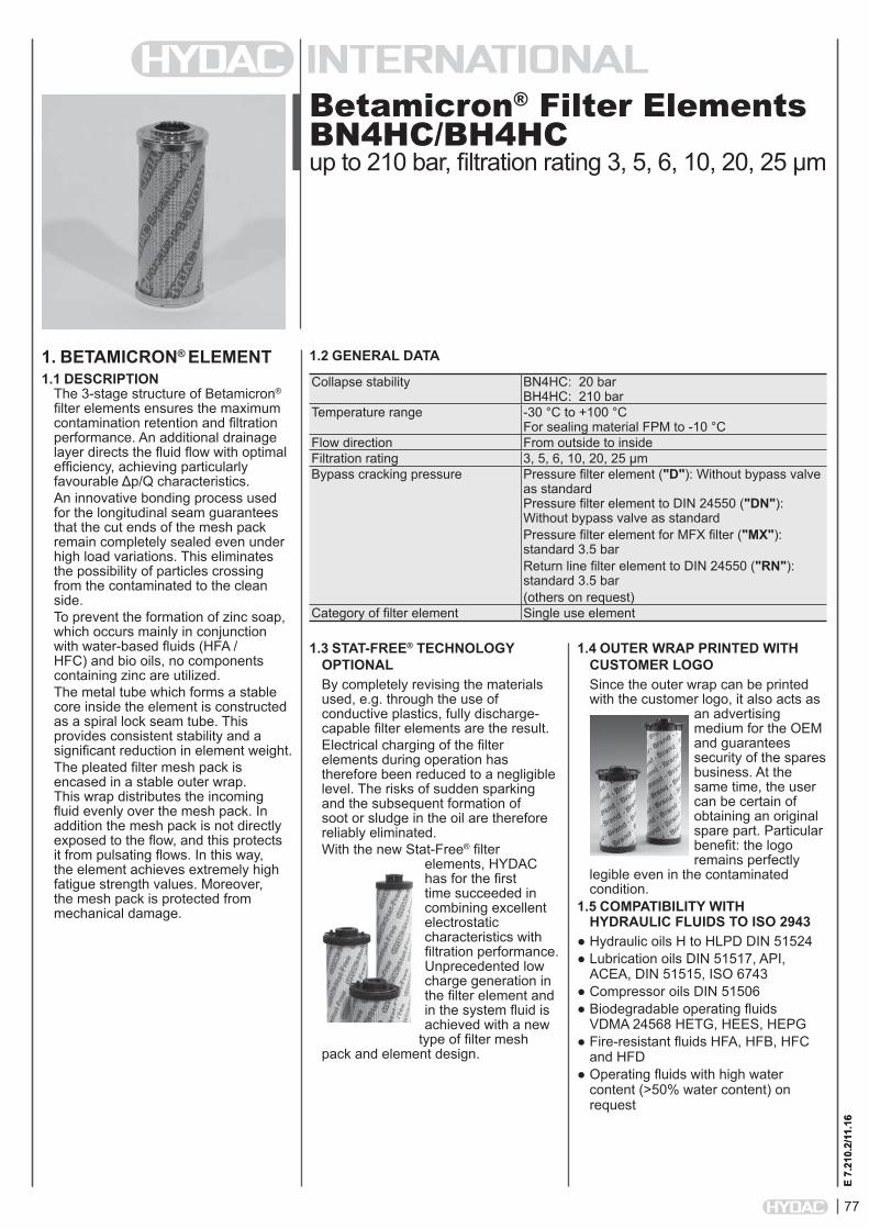
Betamicron® Filter Elements BN4HC/BH4HCup to 210 bar, filtration rating 3, 5, 6, 10, 20, 25 µm
1. BETAMICRON® ELEMENT1.1 DESCRIPTION
The 3-stage structure of Betamicron®
filter elements ensures the maximum contamination retention and filtration performance. An additional drainage layer directs the fluid flow with optimal efficiency, achieving particularly favourable Δp/Q characteristics. An innovative bonding process used for the longitudinal seam guarantees that the cut ends of the mesh pack remain completely sealed even under high load variations. This eliminates the possibility of particles crossing from the contaminated to the clean side.To prevent the formation of zinc soap, which occurs mainly in conjunction with water-based fluids (HFA / HFC) and bio oils, no components containing zinc are utilized. The metal tube which forms a stable core inside the element is constructed as a spiral lock seam tube. This provides consistent stability and a significant reduction in element weight.The pleated filter mesh pack is encased in a stable outer wrap. This wrap distributes the incoming fluid evenly over the mesh pack. In addition the mesh pack is not directly exposed to the flow, and this protects it from pulsating flows. In this way, the element achieves extremely high fatigue strength values. Moreover, the mesh pack is protected from mechanical damage.
1.2 GENERAL DATA
E 7.
210.
2/11
.16
1.3 STAT-FREE® TECHNOLOGY OPTIONALBy completely revising the materials used, e.g. through the use of conductive plastics, fully discharge-capable filter elements are the result. Electrical charging of the filter elements during operation has therefore been reduced to a negligible level. The risks of sudden sparking and the subsequent formation of soot or sludge in the oil are therefore reliably eliminated.With the new Stat-Free® filter
elements, HYDAC has for the first time succeeded in combining excellent electrostatic characteristics with filtration performance. Unprecedented low charge generation in the filter element and in the system fluid is achieved with a new
type of filter mesh pack and element design.
Collapse stability BN4HC: 20 bar BH4HC: 210 bar
Temperature range -30 °C to +100 °C For sealing material FPM to -10 °C
Flow direction From outside to insideFiltration rating 3, 5, 6, 10, 20, 25 µmBypass cracking pressure Pressure filter element ("D"): Without bypass valve
as standard Pressure filter element to DIN 24550 ("DN"): Without bypass valve as standardPressure filter element for MFX filter ("MX"): standard 3.5 barReturn line filter element to DIN 24550 ("RN"): standard 3.5 bar(others on request)
Category of filter element Single use element
1.4 OUTER WRAP PRINTED WITH CUSTOMER LOGOSince the outer wrap can be printed with the customer logo, it also acts as
an advertising medium for the OEM and guarantees security of the spares business. At the same time, the user can be certain of obtaining an original spare part. Particular benefit: the logo remains perfectly
legible even in the contaminated condition.
1.5 COMPATIBILITY WITH HYDRAULIC FLUIDS TO ISO 2943
● Hydraulic oils H to HLPD DIN 51524● Lubrication oils DIN 51517, API,
ACEA, DIN 51515, ISO 6743● Compressor oils DIN 51506● Biodegradable operating fluids
VDMA 24568 HETG, HEES, HEPG● Fire-resistant fluids HFA, HFB, HFC
and HFD ● Operating fluids with high water
content (>50% water content) on request
78
E 7.
210.
2/11
.16
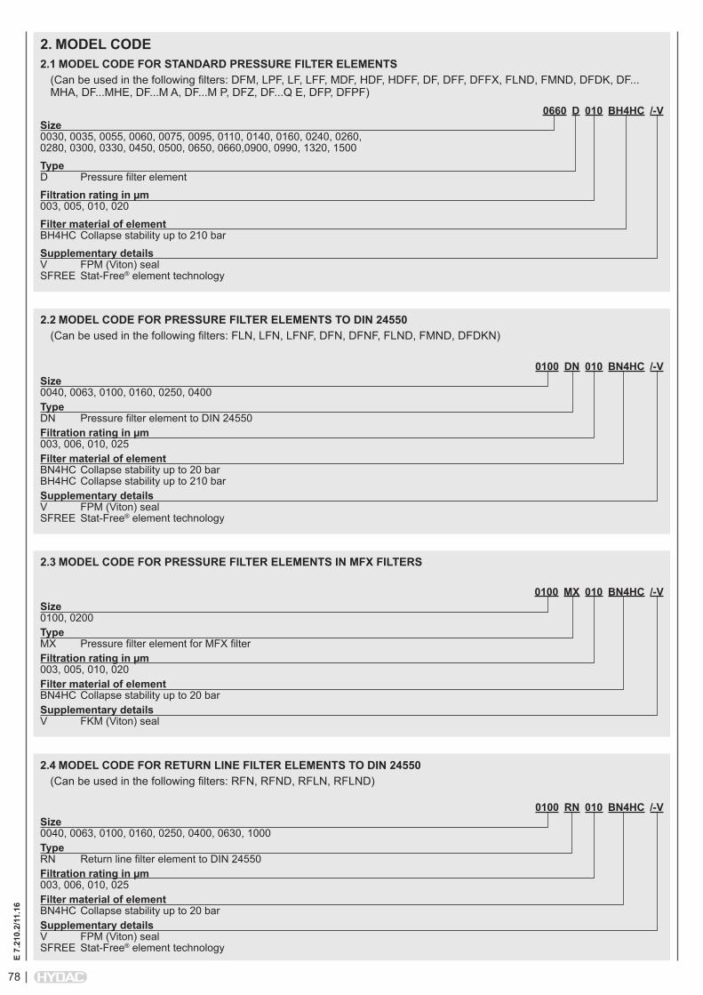
0660 D 010 BH4HC /-VSize 0030, 0035, 0055, 0060, 0075, 0095, 0110, 0140, 0160, 0240, 0260, 0280, 0300, 0330, 0450, 0500, 0650, 0660,0900, 0990, 1320, 1500
Type D Pressure filter element
Filtration rating in µm 003, 005, 010, 020
Filter material of element BH4HC Collapse stability up to 210 bar
Supplementary details V FPM (Viton) seal SFREE Stat-Free® element technology
2.1 MODEL CODE FOR STANDARD PRESSURE FILTER ELEMENTS(Can be used in the following filters: DFM, LPF, LF, LFF, MDF, HDF, HDFF, DF, DFF, DFFX, FLND, FMND, DFDK, DF...MHA, DF...MHE, DF...M A, DF...M P, DFZ, DF...Q E, DFP, DFPF)
2. MODEL CODE
0100 DN 010 BN4HC /-VSize 0040, 0063, 0100, 0160, 0250, 0400Type DN Pressure filter element to DIN 24550Filtration rating in µm 003, 006, 010, 025Filter material of element BN4HC Collapse stability up to 20 bar BH4HC Collapse stability up to 210 barSupplementary details V FPM (Viton) seal SFREE Stat-Free® element technology
2.2 MODEL CODE FOR PRESSURE FILTER ELEMENTS TO DIN 24550(Can be used in the following filters: FLN, LFN, LFNF, DFN, DFNF, FLND, FMND, DFDKN)
0100 MX 010 BN4HC /-VSize 0100, 0200Type MX Pressure filter element for MFX filterFiltration rating in µm 003, 005, 010, 020Filter material of element BN4HC Collapse stability up to 20 barSupplementary details V FKM (Viton) seal
2.3 MODEL CODE FOR PRESSURE FILTER ELEMENTS IN MFX FILTERS
0100 RN 010 BN4HC /-VSize 0040, 0063, 0100, 0160, 0250, 0400, 0630, 1000Type RN Return line filter element to DIN 24550Filtration rating in µm 003, 006, 010, 025Filter material of element BN4HC Collapse stability up to 20 barSupplementary details V FPM (Viton) seal SFREE Stat-Free® element technology
2.4 MODEL CODE FOR RETURN LINE FILTER ELEMENTS TO DIN 24550(Can be used in the following filters: RFN, RFND, RFLN, RFLND)
79
E 7.
210.
2/11
.16
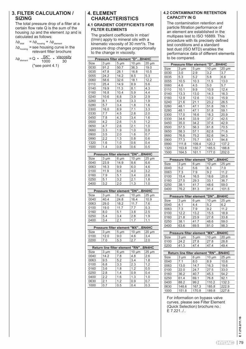
3. FILTER CALCULATION / SIZINGThe total pressure drop of a filter at a certain flow rate Q is the sum of the housing ∆p and the element ∆p and is calculated as follows:∆ptotal = ∆phousing + ∆pelement
∆phousing = see housing curve in the relevant filter brochure
∆pelement = Q • SK* • viscosity 1000 30 (*see point 4.1)
4.2 CONTAMINATION RETENTION CAPACITY IN GThe contamination retention and particle filtration performance of an element are established in the multipass test to ISO 16889. This procedure with its precisely defined test conditions and a standard test dust (ISO MTD) enables the performance data of different elements to be compared.
Pressure filter element "D"...BH4HCSize 3 µm 5 µm 10 µm 20 µm0030 3.0 2.9 3.2 3.70035 5.3 5.2 5.8 6.60055 10.5 10.3 11.5 13.00060 4.6 4.5 5.0 5.70110 10.1 9.9 10.9 12.40140 13.3 13.0 14.3 16.30160 12.9 12.6 13.9 15.90240 21.6 21.1 23.2 26.50260 48.1 47.1 51.8 59.10280 48.1 47.1 51.8 59.10300 17.0 16.6 18.3 20.90330 34.6 33.9 37.2 42.50450 35.0 34.2 37.6 42.90500 57.5 56.3 61.8 70.50650 58.3 57.1 62.8 71.60660 76.8 75.2 82.6 94.30900 77.3 75.7 83.1 94.80990 111.8 109.4 120.2 137.21320 153.8 150.7 165.5 188.81500 164.5 161.1 177.0 202.0
Pressure filter element "DN"...BN4HCSize 3 µm 6 µm 10 µm 25 µm0040 5.2 5.6 6.3 7.00063 7.3 7.9 9.2 11.20100 15.4 16.5 18.6 20.60160 27.5 29.3 33.1 36.70250 38.1 41.7 48.6 59.00400 76.2 81.3 91.4 101.5
Pressure filter element "DN"...BH4HCSize 3 µm 6 µm 10 µm 25 µm0040 4.1 4.4 5.2 6.20063 7.3 7.9 9.2 11.20100 12.2 13.2 15.5 18.90160 21.8 23.9 27.8 33.80250 38.1 41.7 48.6 59.00400 63.6 69.5 81.0 98.3
Pressure filter element "MX"...BN4HCSize 3 µm 5 µm 10 µm 20 µm0100 24.2 27.8 27.8 28.80200 41.3 47.4 47.4 49.4
Return line filter element "RN"...BN4HCSize 3 µm 6 µm 10 µm 25 µm0040 7.1 8.0 8.9 10.60063 13.0 14.7 16.3 19.60100 22.0 24.7 27.5 33.00160 36.2 40.7 45.3 54.20250 61.4 69.1 76.8 92.10400 88.2 99.2 110.2 132.30630 148.6 167.3 185.8 222.91000 151.8 170.8 189.8 227.8
For information on bypass valve curves, please see Filter Element (Quick Selection) brochure no.: E 7.221../..
4. ELEMENT CHARACTERISTICS
4.1 GRADIENT COEFFICIENTS FOR FILTER ELEMENTSThe gradient coefficients in mbar/(l/min) apply to mineral oils with a kinematic viscosity of 30 mm²/s. The pressure drop changes proportionally to the change in viscosity.
Pressure filter element "D"...BH4HCSize 3 µm 5 µm 10 µm 20 µm0030 91.2 50.7 36.3 19.00035 47.8 28.1 16.8 10.50055 24.2 14.2 8.5 5.30060 58.6 32.6 18.1 12.20110 25.4 14.9 8.9 5.60140 19.9 11.3 8.1 4.30160 16.8 10.4 5.9 4.40240 10.6 6.8 3.9 2.90260 8.1 4.8 3.3 1.90280 5.7 3.4 1.8 1.60300 16.0 8.9 7.1 3.30330 7.7 4.5 2.8 2.00450 7.8 4.3 3.4 1.60500 4.2 2.6 1.5 1.20650 4.7 2.6 2.1 1.00660 3.3 1.9 1.0 0.90900 3.5 2.0 1.6 0.70990 2.2 1.3 0.8 0.61320 1.6 1.0 0.6 0.41500 1.4 0.8 0.6 0.5
Pressure filter element "DN"...BN4HCSize 3 µm 6 µm 10 µm 25 µm0040 23.9 14.9 8.6 6.60063 16.3 9.9 6.0 4.60100 11.9 6.6 4.0 3.20160 7.9 5.1 3.4 2.60250 5.1 3.2 2.1 1.80400 3.2 2.0 1.3 1.0
Pressure filter element "DN"...BH4HCSize 3 µm 6 µm 10 µm 25 µm0040 40.4 24.8 16.4 10.90063 29.0 18.2 11.7 7.60100 19.0 11.7 7.7 5.30160 8.0 5.1 3.8 2.50250 5.4 3.4 2.8 1.90400 3.4 2.1 1.7 1.1
Pressure filter element "MX"...BN4HCSize 3 µm 5 µm 10 µm 20 µm0100 12.0 9.0 4.6 3.40200 7.0 5.3 2.7 2.0
Return line filter element "RN"...BN4HCSize 3 µm 6 µm 10 µm 25 µm0040 14.2 7.8 4.8 2.60063 9.5 5.2 3.4 1.80100 6.8 3.3 2.3 1.20160 3.6 1.8 1.2 0.50250 2.8 1.4 0.9 0.40400 2.2 1.6 1.3 1.00630 2.1 1.2 0.9 0.71000 0.7 0.5 0.4 0.3

80
E 7.
210.
2/11
.16
NOTEThe information in this brochure relates to the operating conditions and applications described. For applications or operating conditions not described, please contact the relevant technical department. Subject to technical modifications.
HYDAC Filtertechnik GmbH Industriegebiet D-66280 Sulzbach/Saar Tel.: 0 68 97 / 509-01 Fax: 0 68 97 / 509-300 Internet: www.hydac.com E-Mail: [email protected]
NOTES

81
E 7.
211.
2/11
.16
Mobilemicron®
Filter Elements MMup to 10 bar, filtration rating 8, 10, 15 µm
1. MOBILEMICRON® ELEMENT1.1 DESCRIPTION
The use of Mobilemicron® element technology guarantees safe, reliable operation of your mobile machine.The Mobilemicron® series of filter elements is characterized by an especially low pressure drop which makes them particularly suitable for use wherever high-viscosity oil is likely - especially at low temperatures during a cold start. When Mobilemicron® elements are used, compared to conventional hydraulic elements under the same ambient conditions, the Δp produced is lower and the flow rate is higher which results in a lower energy requirement.
Filtered flow during cold start
Thanks to its excellent cold start behaviour the Mobilemicron® element technology is used primarily in mobile applications but is also typically recommended for gear lubrication applications in systems with high temperature fluctuations and high-viscosity oils (>ISO VG 100).
1.2 GENERAL DATA
E 7.
211.
2/11
.16
1.3 STAT-FREE® ELEMENT TECHNOLOGY OPTIONALBy completely revising the materials used, e.g. through the use of conductive plastics, fully discharge-capable filter elements are the result. Electrical charging of the filter elements during operation has therefore been reduced to a negligible level. The risks of sudden sparking and the subsequent formation of soot or sludge in the oil are therefore reliably eliminated.With the new Stat-Free® filter
elements, HYDAC has for the first time succeeded in combining excellent electrostatic characteristics with filtration performance. Unprecedented low charge generation in the filter element and in the system fluid is achieved with a new
type of filter mesh pack and element design.
Collapse stability 10 bar for return line filter elements 20 bar for pressure filter elements
Temperature range -30 °C to +100 °C For sealing material FPM to -10 °C
Flow direction From outside to insideFiltration rating 8, 10, 15 µmBypass cracking pressure Return line filter element ("R"): standard 3 bar
Pressure filter element for MFX filter ("MX"): standard 3.5 barReturn line filter element for RKM filter ("RK"): standard without bypass valveReturn line filter element pressure filter ("RD"): standard without bypass valve(others on request)
Category of filter element Single use element
1.4 OUTER WRAP PRINTED WITH CUSTOMER LOGOSince the outer wrap can be printed with the customer logo, it also acts as
an advertising medium for the OEM and guarantees security of the spares business. At the same time, the user can be certain of obtaining an original spare part. Particular benefit: the logo remains perfectly
legible even in the contaminated condition.
1.5 COMPATIBILITY WITH HYDRAULIC FLUIDS TO ISO 2943
● Hydraulic oils H to HLPD DIN 51524● Lubrication oils DIN 51517, API,
ACEA, DIN 51515, ISO 6743● Compressor oils DIN 51506● Biodegradable operating fluids VDMA
24568 HETG, HEES, HEPG● Fire-resistant fluids HFA, HFB, HFC
and HFD ● Operating fluids with high water
content (>50% water content) on request
∆p[bar]
Mobilemicron
Standard
Q[l/min]
[bar]
[l/min]

82
E 7.
211.
2/11
.16
2. MODEL CODE
0660 R 010 MM /-VSize 0075, 0090, 0150, 0165, 0185, 0195, 0210, 0270, 0330, 0500, 0660, 0850Type R Return line filter elementFiltration rating in µm 008, 010, 015Filter material of element MM Mobilemicron®, collapse stability up to 10 barSupplementary details V FPM (Viton) seal KB without bypass valve SFREE Stat-Free® element technology
2.1 MODEL CODE FOR STANDARD RETURN LINE FILTER ELEMENTS(Can be used in the following filters: RF, RFD, RFM, RFL, RFLD)
0300 RK 010 MM /-VSize 0080, 0100, 0120, 0151, 0201, 0251, 0300, 0350, 0400, 0800Type RK Return line filter element for RKM filterFiltration rating in µm 008, 010, 015Filter material of element MM Mobilemicron®, collapse stability up to 10 barSupplementary details V FPM (Viton) seal SFREE Stat-Free® element technology
2.2 MODEL CODE FOR RETURN LINE FILTER ELEMENTS IN RKM FILTERS
0251 RD 010 MM /-VSize 0161, 0241, 0261, 0281Type RD Pressure filter elementFiltration rating in µm 008, 010, 015Filter material of element MM Mobilemicron®, collapse stability up to 20 barSupplementary details V FPM (Viton) seal SFREE Stat-Free® element technology
2.3 MODEL CODE FOR RD PRESSURE FILTER ELEMENTS(Can be used in the following filters: LPF…/-TH, LPF…GGA)

83
E 7.
211.
2/11
.16
0100 MX 010 MM /-VSize 0100, 0200Type MX Pressure filter element for MFX filterFiltration rating in µm 008, 010, 015Filter material of element MM Mobilemicron®, collapse stability up to 20 barSupplementary details V FPM (Viton) seal KB without bypass valve SFREE Stat-Free® element technology
2.4 MODEL CODE FOR PRESSURE FILTER ELEMENTS IN MFX FILTERS
3. FILTER CALCULATION / SIZINGThe total pressure drop of a filter at a certain flow rate Q is the sum of the housing ∆p and the element ∆p and is calculated as follows:∆ptotal = ∆phousing + ∆pelement
∆phousing = see housing curve in the relevant filter brochure
∆pelement = Q • SK* • viscosity 1000 30 (*see point 4.1)
4. ELEMENT CHARACTERISTICS
4.1 GRADIENT COEFFICIENTS FOR FILTER ELEMENTSThe gradient coefficients in mbar/(l/min) apply to mineral oils with a kinematic viscosity of 30 mm²/s. The pressure drop changes proportionally to the change in viscosity.
Return line filter element "R"...MMSize 8 µm 10 µm 15 µm0075 4.83 4.83 3.020090 4.60 4.60 2.150150 2.08 2.08 1.300165 2.66 2.66 1.660185 1.97 1.97 1.230195 1.45 1.13 0.690210 0.95 0.95 0.590270 0.58 0.58 0.360330 1.43 1.43 0.890500 0.94 0.94 0.590660 0.55 0.55 0.340850 0.42 0.42 0.26
Return line filter element "RK"...MMSize 8 µm 10 µm 15 µm0080 2.48 2.48 1.590100 1.74 1.74 1.110120 1.40 1.40 0.900151 1.00 1.00 0.650201 0.75 0.75 0.470251 0.58 0.58 0.360300 0.62 0.62 0.390350 0.30 0.30 0.200400 0.56 0.56 0.350800 0.44 0.44 0.27
Pressure filter element "RD"...MMSize 8 µm 10 µm 15 µm0161 3.53 3.53 2.290241 2.03 2.03 1.320261 1.31 1.31 0.850281 0.82 0.82 0.53
Pressure filter element "MX"...MMSize 8 µm 10 µm 15 µm0100 2.70 2.70 2.200200 1.60 1.60 1.30
4.2 CONTAMINATION RETENTION CAPACITY IN GThe contamination retention and particle filtration performance of an element are established in the multipass test to ISO 16889. This procedure with its precisely defined test conditions and a standard test dust (ISO MTD) enables the performance data of different elements to be compared.
Return line filter element "R"...MMSize 8 µm 10 µm 15 µm0075 5.4 5.4 6.40090 7.4 7.4 8.80150 11.8 11.8 13.90165 9.9 9.9 11.60185 13.6 13.6 16.00195 18.5 18.5 21.70210 32.8 32.8 38.70270 50.8 50.8 59.90330 21.8 21.8 25.70500 33.4 33.4 39.40660 53.7 53.7 63.30850 69.1 69.1 81.4
Return line filter element "RK"...MMSize 8 µm 10 µm 15 µm0080 11.0 11.0 13.30100 16.3 16.3 19.60120 20.7 20.7 25.00151 26.6 26.6 31.40201 50.9 50.9 61.40251 61.9 61.9 74.70300 55.6 55.6 67.10350 87.0 87.0 105.00400 67.4 67.4 81.30800 86.3 86.3 104.2
Pressure filter element "RD"...MMSize 8 µm 10 µm 15 µm0161 11.3 11.3 13.70241 18.7 18.7 22.60261 29.0 29.0 35.00281 46.6 46.6 56.2
Pressure filter element "MX"...MMSize 8 µm 10 µm 15 µm0100 13.3 13.3 15.70200 22.7 22.7 26.8
For information on bypass valve curves, please see Filter Element (Quick Selection) brochure no.: E 7.221../..

84
E 7.
211.
2/11
.16
NOTEThe information in this brochure relates to the operating conditions and applications described. For applications or operating conditions not described, please contact the relevant technical department. Subject to technical modifications.
HYDAC Filtertechnik GmbH Industriegebiet D-66280 Sulzbach/Saar Tel.: 0 68 97 / 509-01 Fax: 0 68 97 / 509-300 Internet: www.hydac.com E-Mail: [email protected]
NOTES

85
E 7.
212.
2/11
.16
Ecomicron®
Filter Elements ECON2up to 10 bar, filtration rating 3, 5, 10, 20 µm
1. ECOMICRON® ELEMENT1.1 DESCRIPTION
With the introduction of the new Betamicron® element technology HYDAC has broken new ground in the field of filter technology: with its markedly improved filtration performance the new glass fibre technology delivers a significant reduction in operating costs of both machine and system.
In the second step we were able to incorporate the outstanding values of the new Betamicron®4 technology into the environmentally friendly all-plastic variant Ecomicron®. The result was the new filter element generation Ecomicron®2 with tried-and-tested full-plastic structure and improved performance data.
The typical HYDAC element construction has been retained: the unique outer wrap ensures optimum flow control and protects the high-grade filter medium; the pleated filter mesh pack stabilises the filter element for flow from outside to inside and makes maximum use of the glass fibre capacity.
1.2 GENERAL DATA
E 7.
212.
2/11
.16
Collapse stability 10 barTemperature range -30 °C to +100 °C
For sealing material FPM to -10 °CFlow direction From outside to insideFiltration rating 3, 5, 10, 20 µmBypass cracking pressure Return line filter element ("R"): standard 3 bar
Pressure filter element for MFX filter ("MX"): standard 3.5 bar(others on request)
Category of filter element Single use element
1.3 OUTER WRAP PRINTED WITH CUSTOMER LOGOSince the outer wrap can be printed with the customer logo, it also acts as
an advertising medium for the OEM and guarantees security of the spares business. At the same time, the user can be certain of obtaining an original spare part. Particular benefit: the logo remains perfectly
legible even in the contaminated condition.
1.4 COMPATIBILITY WITH HYDRAULIC FLUIDS ISO 2943
● Hydraulic oils H to HLPD DIN 51524● Lubrication oils DIN 51517, API,
ACEA, DIN 51515, ISO 6743● Compressor oils DIN 51506● Biodegradable operating fluids
VDMA 24568 HETG, HEES, HEPG● Fire-resistant fluids HFA, HFB, HFC
and HFD ● Operating fluids with high water
content (>50% water content) on request
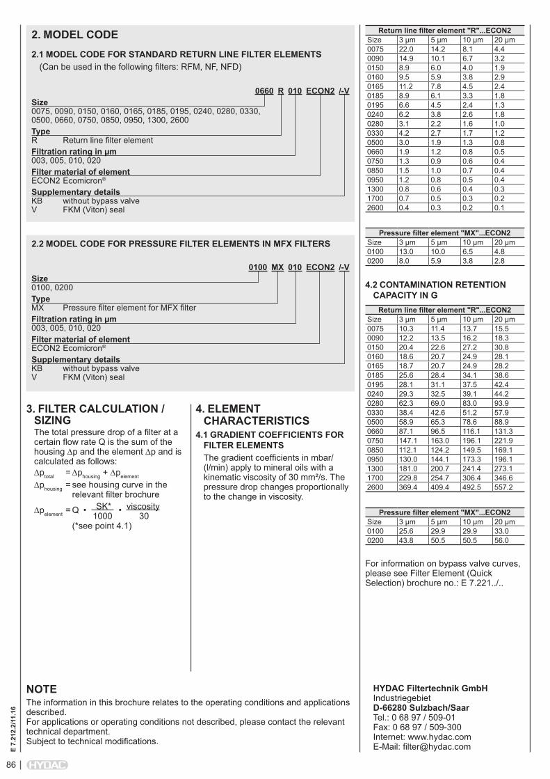
86
E 7.
212.
2/11
.16
2. MODEL CODE
0660 R 010 ECON2 /-VSize 0075, 0090, 0150, 0160, 0165, 0185, 0195, 0240, 0280, 0330, 0500, 0660, 0750, 0850, 0950, 1300, 2600Type R Return line filter elementFiltration rating in µm 003, 005, 010, 020Filter material of element ECON2 Ecomicron®
Supplementary details KB without bypass valve V FKM (Viton) seal
2.1 MODEL CODE FOR STANDARD RETURN LINE FILTER ELEMENTS(Can be used in the following filters: RFM, NF, NFD)
0100 MX 010 ECON2 /-VSize 0100, 0200Type MX Pressure filter element for MFX filterFiltration rating in µm 003, 005, 010, 020Filter material of element ECON2 Ecomicron®
Supplementary details KB without bypass valve V FKM (Viton) seal
2.2 MODEL CODE FOR PRESSURE FILTER ELEMENTS IN MFX FILTERS
3. FILTER CALCULATION / SIZINGThe total pressure drop of a filter at a certain flow rate Q is the sum of the housing ∆p and the element ∆p and is calculated as follows:∆ptotal = ∆phousing + ∆pelement
∆phousing = see housing curve in the relevant filter brochure
∆pelement = Q • SK* • viscosity 1000 30 (*see point 4.1)
Return line filter element "R"...ECON2Size 3 µm 5 µm 10 µm 20 µm0075 22.0 14.2 8.1 4.40090 14.9 10.1 6.7 3.20150 8.9 6.0 4.0 1.90160 9.5 5.9 3.8 2.90165 11.2 7.8 4.5 2.40185 8.9 6.1 3.3 1.80195 6.6 4.5 2.4 1.30240 6.2 3.8 2.6 1.80280 3.1 2.2 1.6 1.00330 4.2 2.7 1.7 1.20500 3.0 1.9 1.3 0.80660 1.9 1.2 0.8 0.50750 1.3 0.9 0.6 0.40850 1.5 1.0 0.7 0.40950 1.2 0.8 0.5 0.41300 0.8 0.6 0.4 0.31700 0.7 0.5 0.3 0.22600 0.4 0.3 0.2 0.1
Pressure filter element "MX"...ECON2Size 3 µm 5 µm 10 µm 20 µm0100 13.0 10.0 6.5 4.80200 8.0 5.9 3.8 2.8
4.2 CONTAMINATION RETENTION CAPACITY IN G
Return line filter element "R"...ECON2Size 3 µm 5 µm 10 µm 20 µm0075 10.3 11.4 13.7 15.50090 12.2 13.5 16.2 18.30150 20.4 22.6 27.2 30.80160 18.6 20.7 24.9 28.10165 18.7 20.7 24.9 28.20185 25.6 28.4 34.1 38.60195 28.1 31.1 37.5 42.40240 29.3 32.5 39.1 44.20280 62.3 69.0 83.0 93.90330 38.4 42.6 51.2 57.90500 58.9 65.3 78.6 88.90660 87.1 96.5 116.1 131.30750 147.1 163.0 196.1 221.90850 112.1 124.2 149.5 169.10950 130.0 144.1 173.3 196.11300 181.0 200.7 241.4 273.11700 229.8 254.7 306.4 346.62600 369.4 409.4 492.5 557.2
Pressure filter element "MX"...ECON2Size 3 µm 5 µm 10 µm 20 µm0100 25.6 29.9 29.9 33.00200 43.8 50.5 50.5 56.0
For information on bypass valve curves, please see Filter Element (Quick Selection) brochure no.: E 7.221../..
NOTEThe information in this brochure relates to the operating conditions and applications described. For applications or operating conditions not described, please contact the relevant technical department. Subject to technical modifications.
HYDAC Filtertechnik GmbH Industriegebiet D-66280 Sulzbach/Saar Tel.: 0 68 97 / 509-01 Fax: 0 68 97 / 509-300 Internet: www.hydac.com E-Mail: [email protected]
4. ELEMENT CHARACTERISTICS
4.1 GRADIENT COEFFICIENTS FOR FILTER ELEMENTSThe gradient coefficients in mbar/(l/min) apply to mineral oils with a kinematic viscosity of 30 mm²/s. The pressure drop changes proportionally to the change in viscosity.
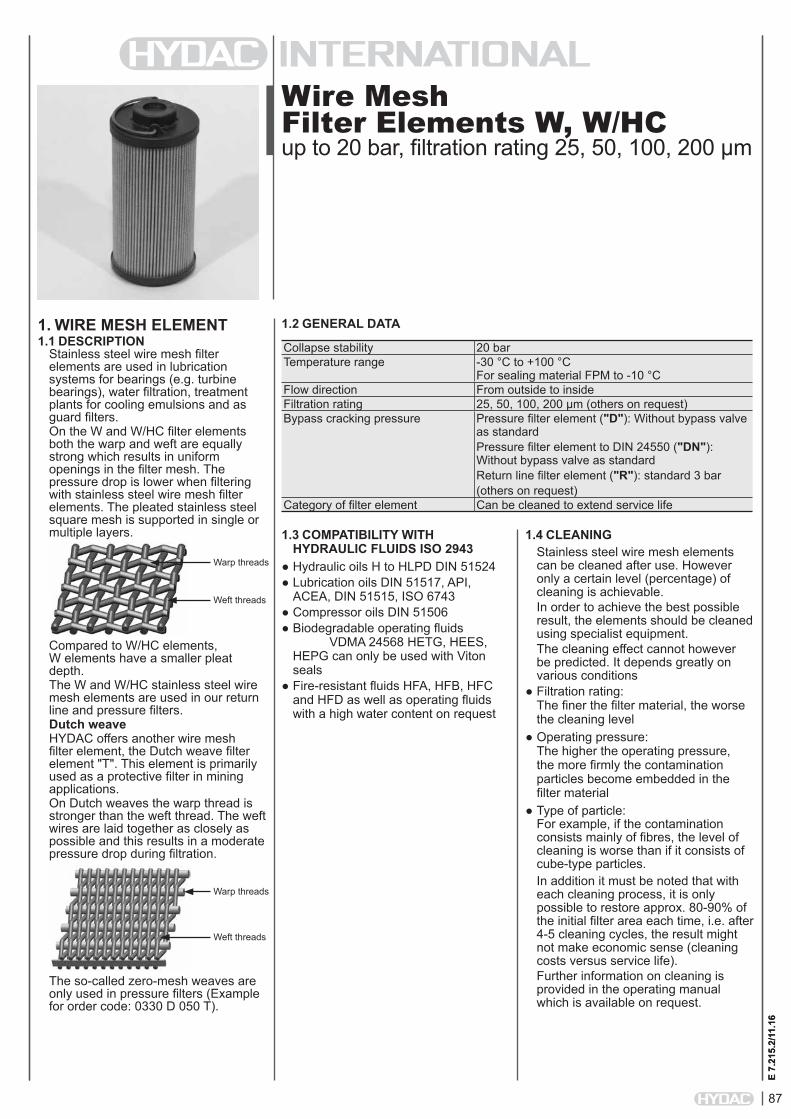
87
E 7.
215.
2/11
.16
Wire Mesh Filter Elements W, W/HCup to 20 bar, filtration rating 25, 50, 100, 200 µm
1. WIRE MESH ELEMENT1.1 DESCRIPTION
Stainless steel wire mesh filter elements are used in lubrication systems for bearings (e.g. turbine bearings), water filtration, treatment plants for cooling emulsions and as guard filters.On the W and W/HC filter elements both the warp and weft are equally strong which results in uniform openings in the filter mesh. The pressure drop is lower when filtering with stainless steel wire mesh filter elements. The pleated stainless steel square mesh is supported in single or multiple layers.
Compared to W/HC elements, W elements have a smaller pleat depth.The W and W/HC stainless steel wire mesh elements are used in our return line and pressure filters.Dutch weaveHYDAC offers another wire mesh filter element, the Dutch weave filter element "T". This element is primarily used as a protective filter in mining applications. On Dutch weaves the warp thread is stronger than the weft thread. The weft wires are laid together as closely as possible and this results in a moderate pressure drop during filtration.
The so-called zero-mesh weaves are only used in pressure filters (Example for order code: 0330 D 050 T).
1.2 GENERAL DATA
E 7.
215.
2/11
.16
1.4 CLEANINGStainless steel wire mesh elements can be cleaned after use. However only a certain level (percentage) of cleaning is achievable.In order to achieve the best possible result, the elements should be cleaned using specialist equipment. The cleaning effect cannot however be predicted. It depends greatly on various conditions
● Filtration rating: The finer the filter material, the worse the cleaning level
● Operating pressure: The higher the operating pressure, the more firmly the contamination particles become embedded in the filter material
● Type of particle: For example, if the contamination consists mainly of fibres, the level of cleaning is worse than if it consists of cube-type particles.In addition it must be noted that with each cleaning process, it is only possible to restore approx. 80-90% of the initial filter area each time, i.e. after 4-5 cleaning cycles, the result might not make economic sense (cleaning costs versus service life).Further information on cleaning is provided in the operating manual which is available on request.
Collapse stability 20 barTemperature range -30 °C to +100 °C
For sealing material FPM to -10 °CFlow direction From outside to insideFiltration rating 25, 50, 100, 200 µm (others on request)Bypass cracking pressure Pressure filter element ("D"): Without bypass valve
as standardPressure filter element to DIN 24550 ("DN"): Without bypass valve as standardReturn line filter element ("R"): standard 3 bar(others on request)
Category of filter element Can be cleaned to extend service life
1.3 COMPATIBILITY WITH HYDRAULIC FLUIDS ISO 2943
● Hydraulic oils H to HLPD DIN 51524● Lubrication oils DIN 51517, API,
ACEA, DIN 51515, ISO 6743● Compressor oils DIN 51506● Biodegradable operating fluids
VDMA 24568 HETG, HEES, HEPG can only be used with Viton seals
● Fire-resistant fluids HFA, HFB, HFC and HFD as well as operating fluids with a high water content on request
Warp threads
Weft threads
Warp threads
Weft threads

88
E 7.
215.
2/11
.16
2. MODEL CODE
0660 D 025 W/HC /-VSize W: 0030, 0060, 0110, 0140, 0160, 0240, 0280, 0330, 0500, 0660, 0990, 1320, 1500 W/HC: 0060, 0110, 0140, 0160, 0240, 0260, 0280, 0330, 0500, 0660, 0990, 1320Type D Pressure filter elementFiltration rating in µm 025, 050, 100, 200Filter material of element W, W/HCSupplementary details V FPM (Viton) seal W suitable for oil-water emulsions (HFA, HFC)
2.1 MODEL CODE FOR STANDARD PRESSURE FILTER ELEMENTS(Can be used in the following filters: LPF, LF, LFF, MDF, DF, DFF, DFFX, DFDK)
0660 R 010 W/HC /-VSize 0030, 0060, 0075, 0090, 0110, 0150, 0160, 0165, 0185, 0195, 0210, 0240, 0270, 0280, 0330, 0450, 0500, 0580, 0660, 0750, 0850, 0950, 1300, 1700, 2600, 2700Type R Return line filter elementFiltration rating in µm 025, 050, 100, 200Filter material of element W/HC Collapse stability up to 20 barSupplementary details KB without bypass valve V FKM (Viton) seal W suitable for oil-water emulsions (HFA, HFC)
2.3 MODEL CODE FOR STANDARD RETURN LINE FILTER ELEMENTS(Can be used in the following filters: RFM, RF, RFD, RFL, RFLD, NF, NFD)
0100 DN 025 W/HC /-VSize W: 0040, 0063, 0100 (only for FLND and FMND) W/HC: 0040, 0063, 0100, 0160, 0250, 0400Type DN Pressure filter element to DIN 24550Filtration rating in µm 025, 050, 100, 200Filter material of element W, W/HCSupplementary details V FPM (Viton) seal W suitable for oil-water emulsions (HFA, HFC)
2.2 MODEL CODE FOR PRESSURE FILTER ELEMENTS TO DIN 24550(Can be used in the following filters: FLN, LFN, LFNF, DFN, DFNF, FLND, FMND)

89
E 7.
215.
2/11
.16
3. FILTER CALCULATION / SIZINGThe total pressure drop of a filter at a certain flow rate Q is the sum of the housing ∆p and the element ∆p and is calculated as follows:∆ptotal = ∆phousing + ∆pelement
∆phousing = see housing curve in the relevant filter brochure
∆pelement = Q • SK* • viscosity 1000 30 (*see point 4.1)
4. ELEMENT CHARACTERISTICS
4.1 GRADIENT COEFFICIENTS FOR FILTER ELEMENTSThe gradient coefficients in mbar/(l/min) apply to mineral oils with a kinematic viscosity of 30 mm²/s. The pressure drop changes proportionally to the change in viscosity.Details for 25, 50, 100, 200 µm
Pressure filter element "D"...Size W W/HC0030 3.030 -0060 0.757 0.7570110 0.413 0.4130140 0.324 0.3240160 0.284 0.2840240 0.189 0.1890260 0.131 0.1310280 0.089 0.0890330 0.138 0.1380500 0.091 0.0910660 0.069 0.0690990 0.046 0.0461320 0.035 0.0351500 0.020 -
Pressure filter element "DN"...Size W W/HC0040 0.602 0.7270063 0.374 0.4160100 0.232 0.2510160 - 0.1270250 - 0.0800400 - 0.046
Return line filter element "R"...Size W/HC0030 1.2120060 0.6120075 0.3620090 0.3120110 0.300150 0.1850160 0.1930165 0.1990185 0.9070195 0.6680210 0.0680240 0.1230270 0.0440280 0.0600330 0.1950450 0.1650500 0.1280580 0.0650660 0.0670750 0.0550850 0.0520950 0.0481300 0.0341700 0.0252600 0.0172700 0.020
4.2 FILTRATION AREA [CM²]Pressure filter element "D"...
Size W W/HC0030 256 -0060 330 4180110 672 9100140 884 12000160 857 11440240 1348 19110280 2862 42640330 1795 31330500 2891 51070660 3795 69580990 5431 100911320 7378 139161500 12966 -
Pressure filter element "DN"...Size W W/HC0040 415 4270063 743 7450100 1234 12340160 - 24390250 - 38670400 - 6726
Return line filter element "R"...Size W/HC0030 2560060 5070075 8570090 9940110 10340150 16740160 16070165 15560185 21130195 28700210 45560240 25270270 70420280 51880330 36950450 44130500 56510580 112030660 82320750 132170850 105990950 115211300 160991700 217302600 328472700 28328
For information on bypass valve curves, please see Filter Element (Quick Selection) brochure no.: E 7.221../..
90
E 7.
215.
2/11
.16
NOTEThe information in this brochure relates to the operating conditions and applications described. For applications or operating conditions not described, please contact the relevant technical department. Subject to technical modifications.
HYDAC Filtertechnik GmbH Industriegebiet D-66280 Sulzbach/Saar Tel.: 0 68 97 / 509-01 Fax: 0 68 97 / 509-300 Internet: www.hydac.com E-Mail: [email protected]
NOTES

91
E 7.
216.
2/11
.16
Metal Fibre Filter Elements Vup to 210 bar, filtration rating 3, 5, 10, 20 µm
1. METAL FIBRE ELEMENT1.1 DESCRIPTION
Metal fibre filter elements are used primarily as protective filters in highly dynamic applications.
The filter element is constructed from randomly laid stainless steel wires. This stainless steel wire meshpack which is pleated, produces a low pressure drop and is suitable for all operating fluids.
The "V" metal fibre elements are used in our return line and pressure filters.
Additional metal fibre version "VB"An additional metal fibre filter element offered by HYDAC is the "VB" element. This element is used primarily in test rig systems for test cycles where temperatures exceed 100°C and as working filters in highly dynamic applications. VB filter elements are used mainly in HYDAC pressure filters. (Order code example: 0110 D 005 VB).
1.3 GENERAL DATA
E 7.
216.
2/11
.16
Collapse stability 210 barTemperature range -30 °C to +100 °C
For sealing material FPM to -10 °CFlow direction From outside to insideFiltration rating 3, 5, 10, 20 µm (others on request)Bypass cracking pressure Pressure filter element ("D"): Without bypass valve
as standardReturn line filter element ("R"): standard 3 bar(others on request)
Category of filter element Can be cleaned to extend service life
1.4 CLEANINGStainless steel wire mesh elements can be cleaned after use. However only a certain level (percentage) of cleaning is achievable.In order to achieve the best possible result, the elements should be cleaned using specialist equipment. The cleaning effect cannot however be predicted. It depends greatly on various conditions
● Filtration rating: The finer the filter material, the worse the cleaning level
● Operating pressure: The higher the operating pressure, the more firmly the contamination particles become embedded in the filter material
● Type of particle: For example, if the contamination consists mainly of fibres, the level of cleaning is worse than if it consists of cube-type particles.In addition it must be noted that with each cleaning process, it is only possible to restore approx. 80-90% of the initial filter area each time, i.e. after 4-5 cleaning cycles, the result might not make economic sense (cleaning costs versus service life).Further information on cleaning is provided in the operating manual which is available on request.
1.3 COMPATIBILITY WITH HYDRAULIC FLUIDS ISO 2943
● Hydraulic oils H to HLPD DIN 51524● Lubrication oils DIN 51517, API,
ACEA, DIN 51515, ISO 6743● Compressor oils DIN 51506● Biodegradable operating fluids
VDMA 24568 HETG, HEES, HEPG● Fire-resistant fluids HFA, HFB, HFC
and HFD ● Operating fluids with high water
content (>50% water content) on request
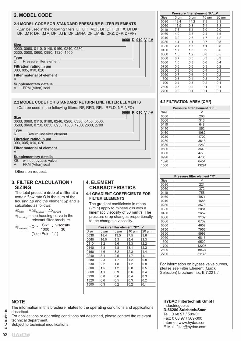
92
E 7.
216.
2/11
.16
2. MODEL CODE
0660 D 010 V /-VSize 0030, 0060, 0110, 0140, 0160, 0240, 0280, 0330, 0500, 0660, 0990, 1320, 1500Type D Pressure filter elementFiltration rating in µm 003, 005, 010, 020Filter material of element VSupplementary details V FPM (Viton) seal
2.1 MODEL CODE FOR STANDARD PRESSURE FILTER ELEMENTS(Can be used in the following filters: LF, LFF, MDF, DF, DFF, DFFX, DFDK, DF…M P, DF…M A, DF…Q E, DF…MHA, DF…MHE, DFZ, DFP, DFPF)
0660 R 010 V /-VSize 0030, 0060, 0110, 0160, 0240, 0280, 0330, 0450, 0500, 0580, 0660, 0750, 0850, 0950, 1300, 1700, 2600, 2700Type R Return line filter elementFiltration rating in µm 003, 005, 010, 020Filter material of element VSupplementary details KB without bypass valve V FKM (Viton) seal
2.2 MODEL CODE FOR STANDARD RETURN LINE FILTER ELEMENTS(Can be used in the following filters: RF, RFD, RFL, RFLD, NF, NFD)
3. FILTER CALCULATION / SIZINGThe total pressure drop of a filter at a certain flow rate Q is the sum of the housing ∆p and the element ∆p and is calculated as follows:∆ptotal = ∆phousing + ∆pelement
∆phousing = see housing curve in the relevant filter brochure
∆pelement = Q • SK* • viscosity 1000 30 (*see Point 4.1)
Pressure filter element "R"...VSize 3 µm 5 µm 10 µm 20 µm0030 19.4 14.2 7.9 3.80060 15.9 9.3 5.4 3.30110 7.6 5.1 3.0 2.00160 4.9 3.5 2.4 1.50240 3.2 2.6 1.7 1.20280 1.4 1.1 0.7 0.50330 2.1 1.7 1.1 0.80450 1.7 1.3 0.9 0.60500 1.5 1.2 0.8 0.50580 0.7 0.5 0.3 0.30660 1.0 0.8 0.6 0.40750 0.6 0.5 0.3 0.20850 0.8 0.6 0.4 0.30950 0.7 0.6 0.4 0.21300 0.5 0.4 0.3 0.21700 0.4 0.3 0.2 0.12600 0.3 0.2 0.1 0.12700 0.2 0.1 0.1 0.1
4.2 FILTRATION AREA [CM²]Pressure filter element "D"...
Size V0030 2680060 3180110 6480140 8520160 10820240 17020280 36150330 22600500 36400660 47700990 47351320 64541500 13294
Pressure filter element "R"Size V0030 2210060 3720110 7580160 10710240 16850280 35780330 20810450 26520500 31820580 67320660 46590750 79560850 59990950 68131300 95201700 122972600 194242700 31175
For information on bypass valve curves, please see Filter Element (Quick Selection) brochure no.: E 7.221../..
NOTEThe information in this brochure relates to the operating conditions and applications described. For applications or operating conditions not described, please contact the relevant technical department. Subject to technical modifications.
HYDAC Filtertechnik GmbH Industriegebiet D-66280 Sulzbach/Saar Tel.: 0 68 97 / 509-01 Fax: 0 68 97 / 509-300 Internet: www.hydac.com E-Mail: [email protected]
Others on request.
4. ELEMENT CHARACTERISTICS
4.1 GRADIENT COEFFICIENTS FOR FILTER ELEMENTSThe gradient coefficients in mbar/(l/min) apply to mineral oils with a kinematic viscosity of 30 mm²/s. The pressure drop changes proportionally to the change in viscosity.
Pressure filter element "D"...VSize 3 µm 5 µm 10 µm 20 µm0030 18.4 13.5 7.5 3.60060 16.0 9.3 5.4 3.30110 8.2 5.6 3.3 2.20140 5.8 4.8 3.1 2.30160 4.6 3.2 2.3 1.40240 3.1 2.5 1.7 1.10280 2.3 1.7 1.2 0.80330 2.2 1.8 1.2 0.80500 1.5 1.2 0.8 0.50660 1.1 0.9 0.6 0.40990 0.8 0.6 0.4 0.31320 0.6 0.5 0.3 0.21500 0.3 0.2 0.2 0.1
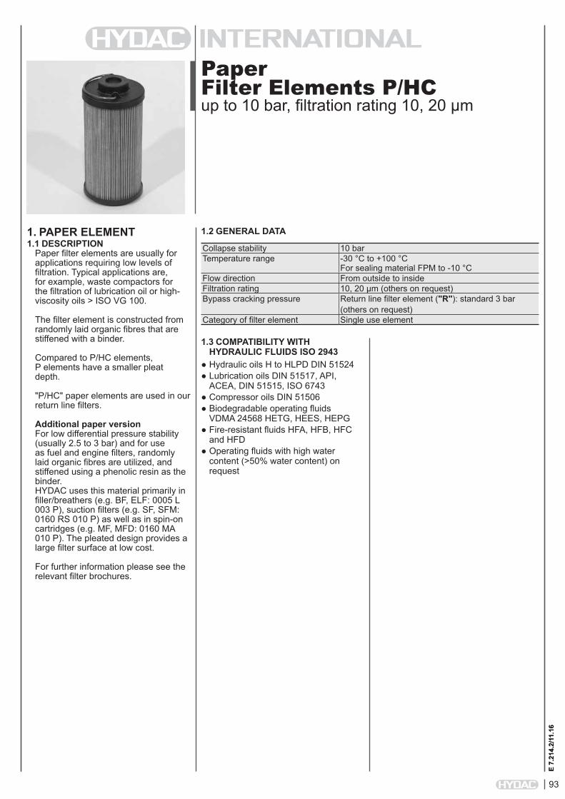
93
E 7.
214.
2/11
.16
Paper Filter Elements P/HCup to 10 bar, filtration rating 10, 20 µm
1. PAPER ELEMENT1.1 DESCRIPTION
Paper filter elements are usually for applications requiring low levels of filtration. Typical applications are, for example, waste compactors for the filtration of lubrication oil or high-viscosity oils > ISO VG 100.
The filter element is constructed from randomly laid organic fibres that are stiffened with a binder.
Compared to P/HC elements, P elements have a smaller pleat depth.
"P/HC" paper elements are used in our return line filters.
Additional paper versionFor low differential pressure stability (usually 2.5 to 3 bar) and for use as fuel and engine filters, randomly laid organic fibres are utilized, and stiffened using a phenolic resin as the binder. HYDAC uses this material primarily in filler/breathers (e.g. BF, ELF: 0005 L 003 P), suction filters (e.g. SF, SFM: 0160 RS 010 P) as well as in spin-on cartridges (e.g. MF, MFD: 0160 MA 010 P). The pleated design provides a large filter surface at low cost.
For further information please see the relevant filter brochures.
1.2 GENERAL DATA
E 7.
214.
2/11
.16
Collapse stability 10 barTemperature range -30 °C to +100 °C
For sealing material FPM to -10 °CFlow direction From outside to insideFiltration rating 10, 20 µm (others on request)Bypass cracking pressure Return line filter element ("R"): standard 3 bar
(others on request)Category of filter element Single use element
1.3 COMPATIBILITY WITH HYDRAULIC FLUIDS ISO 2943
● Hydraulic oils H to HLPD DIN 51524● Lubrication oils DIN 51517, API,
ACEA, DIN 51515, ISO 6743● Compressor oils DIN 51506● Biodegradable operating fluids
VDMA 24568 HETG, HEES, HEPG● Fire-resistant fluids HFA, HFB, HFC
and HFD ● Operating fluids with high water
content (>50% water content) on request
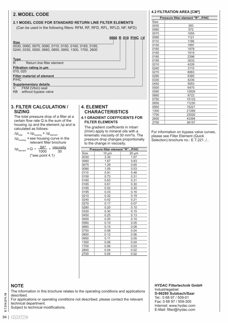
94
E 7.
214.
2/11
.16
2. MODEL CODE
0660 R 010 P/HC /-VSize 0030, 0060, 0075, 0090, 0110, 0150, 0160, 0165, 0185, 0240, 0330, 0500, 0660, 0850, 0950, 1300, 1700, 2600
Type R Return line filter elementFiltration rating in µm 010, 020Filter material of element P/HCSupplementary details V FKM (Viton) seal KB without bypass valve
2.1 MODEL CODE FOR STANDARD RETURN LINE FILTER ELEMENTS(Can be used in the following filters: RFM, RF, RFD, RFL, RFLD, NF, NFD)
3. FILTER CALCULATION / SIZINGThe total pressure drop of a filter at a certain flow rate Q is the sum of the housing ∆p and the element ∆p and is calculated as follows:∆ptotal = ∆phousing + ∆pelement
∆phousing = see housing curve in the relevant filter brochure
∆pelement = Q • SK* • viscosity 1000 30 (*see point 4.1)
4.2 FILTRATION AREA [CM²]Pressure filter element "R"...P/HC
Size0030 2830060 5720075 10550090 11210110 11660150 18970160 19780165 19150185 23980195 35330210 42260240 31100270 80630280 63850330 42300450 50530500 64700580 128260660 87220750 151330850 112300950 152211300 212691700 230202600 433942700 36157
For information on bypass valve curves, please see Filter Element (Quick Selection) brochure no.: E 7.221../..
NOTEThe information in this brochure relates to the operating conditions and applications described. For applications or operating conditions not described, please contact the relevant technical department. Subject to technical modifications.
HYDAC Filtertechnik GmbH Industriegebiet D-66280 Sulzbach/Saar Tel.: 0 68 97 / 509-01 Fax: 0 68 97 / 509-300 Internet: www.hydac.com E-Mail: [email protected]
4. ELEMENT CHARACTERISTICS
4.1 GRADIENT COEFFICIENTS FOR FILTER ELEMENTSThe gradient coefficients in mbar/(l/min) apply to mineral oils with a kinematic viscosity of 30 mm²/s. The pressure drop changes proportionally to the change in viscosity.
Pressure filter element "R"...P/HCSize 10 µm 20 µm0030 3.30 1.670060 1.67 0.830075 1.29 0.650090 1.05 0.530110 0.91 0.460150 0.73 0.310160 0.63 0.310165 0.61 0.300185 0.52 0.300195 0.33 0.160210 0.32 0.190240 0.42 0.210270 0.17 0.070280 0.20 0.100330 0.30 0.150450 0.25 0.130500 0.20 0.100580 0.10 0.050660 0.15 0.080750 0.08 0.040850 0.12 0.060950 0.11 0.051300 0.08 0.041700 0.06 0.032600 0.04 0.022700 0.05 0.02

95
E 7.
217.
2/11
.16
Aquamicron®- Filter Elements AMup to 10 bar, filtration rating 40 µm
1. AQUAMICRON® ELEMENT1.1 DESCRIPTION
The presence of water in hydraulic media is a frequent cause of failures, for example, blinding of very fine filters or jamming of valves, and these problems are often incorrectly attributed to excessive levels of solid contamination. In addition, the formation of rust and the reduction in lubricity on bearings and slideways can result in significant deterioration in system function. In other words, water is itself a serious "contaminant" of the hydraulic medium. Since the conventional methods of dewatering are in most cases uneconomical in relation to the purchase price of the system, HYDAC Aquamicron® technology provides an economically acceptable, yet effective method of separating water from hydraulic media.Aquamicron® filter elements are specifically designed to separate water from mineral oils, HFD-R oils and biodegradable oils. They are only available in the dimensions to suit HYDAC return line filter elements, size 330 and above. They can therefore be installed in all HYDAC filter housings, size 330 and above, which are equipped with return line filter elements.The increasing pressure drop across the filter element which is becoming "saturated" with water indicates, with the aid of standard clogging indicators, that it is time to change the element. As an added bonus when using the Aquamicron® technology, solid contamination is also filtered out of the hydraulic medium. This means the Aquamicron® element also doubles as a safety filter. The filtration rating is 40 µm absolute. To guarantee maximum efficiency it is recommended that they are installed offline.
1.2 GENERAL DATA
E 7.
217.
2/11
.16
Max. permitted operating pressure 25 barMax. permitted Δp across element 10 barTemperature range 0 °C to +100 °CFlow direction From outside to insideFiltration rating 40 µmBypass cracking pressure Return line filter element ("R"): standard 3 bar
(others on request)Category of filter element Single use element
1.3 PRINCIPLES OF AQUAMICRON® TECHNOLOGYThe separation of water from hydraulic fluids with the aid of the superabsorber embedded in the filter material is based on a physico-chemical reaction. The superabsorber reacts with the water present in the medium and expands to form a gel. This reaction is not reversible, even under increased pressure. The Aquamicron® technology is capable of absorbing circulating water, be it emulsified or free. These filter elements cannot remove dissolved water from the system, i.e. water below the saturation level of the hydraulic medium.
1.4 COMPATIBILITY WITH HYDRAULIC FLUIDS ISO 2943
● Hydraulic oils H to HLPD DIN 51524● Lubrication oils DIN 51517, API,
ACEA, DIN 51515, ISO 6743● Compressor oils DIN 51506● Biodegradable operating fluids
VDMA 24568 HETG, HEES, HEPG● Fire-resistant pressure fluid HFD
The following principles apply to Aquamicron® technology:
High water content High absorption rateLow water content Low absorption rateUnsaturated filter element High absorption rateSaturated filter element Low absorption rateHydraulic filter area load (l/min/cm²)
Absorption rate Water absorption capacity Residual water content
Static pressure Absorption rate Water absorption capacity Residual water content
= =
Pressure and flow rate fluctuations present
Absorption rate Water absorption capacity Residual water content
Dispersant/detergent additives present
Absorption rate Water absorption capacity Residual water content
=
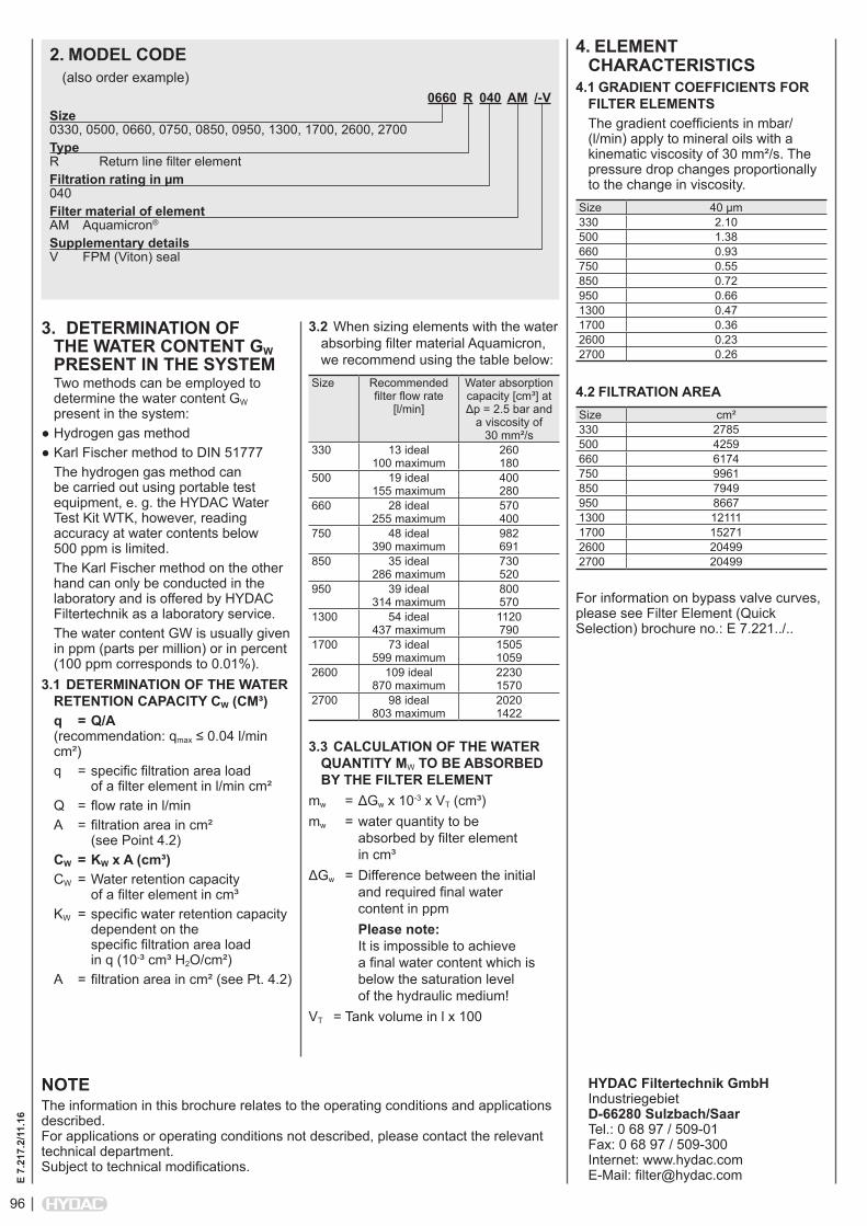
96
E 7.
217.
2/11
.16
2. MODEL CODE
0660 R 040 AM /-VSize 0330, 0500, 0660, 0750, 0850, 0950, 1300, 1700, 2600, 2700Type R Return line filter elementFiltration rating in µm 040Filter material of element AM Aquamicron®
Supplementary details V FPM (Viton) seal
(also order example)
3. DETERMINATION OF THE WATER CONTENT GW PRESENT IN THE SYSTEMTwo methods can be employed to determine the water content GW present in the system:
● Hydrogen gas method ● Karl Fischer method to DIN 51777
The hydrogen gas method can be carried out using portable test equipment, e. g. the HYDAC Water Test Kit WTK, however, reading accuracy at water contents below 500 ppm is limited.The Karl Fischer method on the other hand can only be conducted in the laboratory and is offered by HYDAC Filtertechnik as a laboratory service.The water content GW is usually given in ppm (parts per million) or in percent (100 ppm corresponds to 0.01%).
3.1 DETERMINATION OF THE WATER RETENTION CAPACITY CW (CM³)q = Q/A (recommendation: qmax ≤ 0.04 l/min cm²)q = specific filtration area load of a filter element in l/min cm² Q = flow rate in l/minA = filtration area in cm² (see Point 4.2)CW = KW x A (cm³)CW = Water retention capacity of a filter element in cm³KW = specific water retention capacity dependent on the specific filtration area load in q (10-³ cm³ H2O/cm²) A = filtration area in cm² (see Pt. 4.2)
NOTEThe information in this brochure relates to the operating conditions and applications described. For applications or operating conditions not described, please contact the relevant technical department. Subject to technical modifications.
HYDAC Filtertechnik GmbH Industriegebiet D-66280 Sulzbach/Saar Tel.: 0 68 97 / 509-01 Fax: 0 68 97 / 509-300 Internet: www.hydac.com E-Mail: [email protected]
4. ELEMENT CHARACTERISTICS
4.1 GRADIENT COEFFICIENTS FOR FILTER ELEMENTSThe gradient coefficients in mbar/(l/min) apply to mineral oils with a kinematic viscosity of 30 mm²/s. The pressure drop changes proportionally to the change in viscosity.
Size 40 µm330 2.10500 1.38660 0.93750 0.55850 0.72950 0.661300 0.471700 0.362600 0.232700 0.26
4.2 FILTRATION AREASize cm²330 2785500 4259660 6174750 9961850 7949950 86671300 121111700 152712600 204992700 20499
For information on bypass valve curves, please see Filter Element (Quick Selection) brochure no.: E 7.221../..
3.2 When sizing elements with the water absorbing filter material Aquamicron, we recommend using the table below:
Size Recommended filter flow rate
[l/min]
Water absorption capacity [cm³] at Δp = 2.5 bar and
a viscosity of 30 mm²/s
330 13 ideal 100 maximum
260 180
500 19 ideal 155 maximum
400 280
660 28 ideal 255 maximum
570 400
750 48 ideal 390 maximum
982 691
850 35 ideal 286 maximum
730 520
950 39 ideal 314 maximum
800 570
1300 54 ideal 437 maximum
1120 790
1700 73 ideal 599 maximum
1505 1059
2600 109 ideal 870 maximum
2230 1570
2700 98 ideal 803 maximum
2020 1422
3.3 CALCULATION OF THE WATER QUANTITY MW TO BE ABSORBED BY THE FILTER ELEMENT
mw = ΔGw x 10-3 x VT (cm³)mw = water quantity to be
absorbed by filter element in cm³
ΔGw = Difference between the initial and required final water content in ppm
Please note: It is impossible to achieve a final water content which is below the saturation level of the hydraulic medium!
VT = Tank volume in l x 100
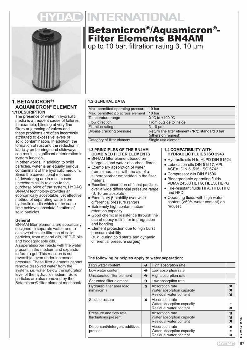
97
E 7.
218.
2/11
.16
Betamicron®/Aquamicron®- Filter Elements BN4AMup to 10 bar, filtration rating 3, 10 µm
1. BETAMICRON®/AQUAMICRON® ELEMENT
1.1 DESCRIPTIONThe presence of water in hydraulic media is a frequent cause of failures, for example, blinding of very fine filters or jamming of valves and these problems are often incorrectly attributed to excessive levels of solid contamination. In addition, the formation of rust and the reduction in lubricity on bearings and slideways can result in significant deterioration in system function. In other words, in addition to solid particles, water is an equally serious contaminant of the hydraulic medium. Since the conventional methods of dewatering are in most cases uneconomical in relation to the purchase price of the system, HYDAC BN4AM technology provides an economically acceptable, yet effective method of separating water from hydraulic media which at the same time achieves absolute filtration of solid particles.
GeneralBN4AM filter elements are specifically designed to separate water, and to achieve absolute filtration of solid particles, from mineral oils, HFD-R oils and biodegradable oils.A superabsorber reacts with the water present in the medium and expands to form a gel. This reaction is not reversible, even under increased pressure. These filter elements cannot remove dissolved water from the system, i.e. water below the saturation level of the hydraulic medium. Solid particles are also removed by the Betamicron® filter element meshpack.
1.2 GENERAL DATA
E 7.
218.
2/11
.16
Max. permitted operating pressure 10 barMax. permitted Δp across element 10 barTemperature range 0 °C to +100 °CFlow direction From outside to insideFiltration rating 3, 10 µmBypass cracking pressure Return line filter element ("R"): standard 3 bar
(others on request)Category of filter element Single use element
1.3 PRINCIPLES OF THE BN4AM COMBINED FILTER ELEMENTS
● BN4AM filter element based on inorganic and water-absorbent fibres
● Exemplary absorption of water from mineral oils with the aid of a superabsorber embedded in the filter material
● Excellent absorption of finest particles over a wide differential pressure range (3, 10 µm absolute)
● Exemplary β-stability over wide differential pressure ranges
● Extremely high contamination retention capacity
● Good chemical resistence through the use of epoxy resins for impregnation and bonding
● Element protection due to high burst pressure stability (e. g. during cold starts and dynamic differential pressure surges)
1.4 COMPATIBILITY WITH HYDRAULIC FLUIDS ISO 2943
● Hydraulic oils H to HLPD DIN 51524● Lubrication oils DIN 51517, API,
ACEA, DIN 51515, ISO 6743● Compressor oils DIN 51506● Biodegradable operating fluids
VDMA 24568 HETG, HEES, HEPG● Fire-resistant fluids HFA, HFB, HFC
and HFD ● Operating fluids with high water
content (>50% water content) on request
The following principles apply to water separation:
High water content High absorption rateLow water content Low absorption rateUnsaturated filter element High absorption rateSaturated filter element Low absorption rateHydraulic filter area load (l/min/cm²)
Absorption rate Water absorption capacity Residual water content
Static pressure Absorption rate Water absorption capacity Residual water content
= =
Pressure and flow rate fluctuations present
Absorption rate Water absorption capacity Residual water content
Dispersant/detergent additives present
Absorption rate Water absorption capacity Residual water content
=

98
E 7.
218.
2/11
.16
2. MODEL CODE
0660 R 010 BN4AM /-VSize 0330, 0500, 0660, 0750, 0850, 0950, 1300, 1700, 2600, 2700Type R Return line filter elementFiltration rating in µm 003, 010Filter material of element BN4AM Betamicron®/Aquamicron®
Supplementary details V FPM (Viton) seal
(also order example)
NOTEThe information in this brochure relates to the operating conditions and applications described. For applications or operating conditions not described, please contact the relevant technical department. Subject to technical modifications.
HYDAC Filtertechnik GmbH Industriegebiet D-66280 Sulzbach/Saar Tel.: 0 68 97 / 509-01 Fax: 0 68 97 / 509-300 Internet: www.hydac.com E-Mail: [email protected]
3. DETERMINATION OF THE WATER CONTENT GW PRESENT IN THE SYSTEMTwo methods can be employed to determine the water content GW present in the system:
● Hydrogen gas method ● Karl Fischer method to DIN 51777
The hydrogen gas method can be carried out using portable test equipment, e. g. the HYDAC Water Test Kit WTK, however, reading accuracy at water contents below 500 ppm is limited.The Karl Fischer method on the other hand can only be conducted in the laboratory and is offered by HYDAC Filtertechnik as a laboratory service. The water content GW is usually given in ppm (parts per million) or in percent (100 ppm corresponds to 0.01%).
3.1 WATER ABSORPTION - QUICK SIZING TABLE
Size Recommended filter flow rate
[l/min]
Water absorption capacity [cm³] at Δp = 2.5 bar and
a viscosity of 30 mm²/s
330 13 180500 19 280660 28 400750 48 691850 35 520950 39 5701300 54 7901700 73 10592600 109 15702700 98 1422
5. ELEMENT CHARACTERISTICS
5.1 GRADIENT COEFFICIENTS FOR FILTER ELEMENTSThe gradient coefficients in mbar/(l/min) apply to mineral oils with a kinematic viscosity of 30 mm²/s. The pressure drop changes proportionally to the change in viscosity.
Size 3 µm 10 µm330 8.7 3.0500 5.7 2.0660 3.5 1.2750 2.3 0.8850 2.8 0.9950 2.4 0.81300 1.6 0.61700 1.3 0.52600 0.8 0.32700 1.0 0.3
5.2 CONTAMINATION RETENTION CAPACITY IN GThe contamination retention and particle filtration performance of an element are established in the multipass test to ISO 16889. This procedure with its precisely defined test conditions and a standard test dust (ISO MTD) enables the performance data of different elements to be compared.
Size 3 µm 10 µm330 55.0 60.0500 83.9 93.9660 120.0 140.0750 209.3 234.5850 156.5 175.3950 170.0 190.01300 240.0 270.01700 320.8 359.42600 490.0 540.02700 430.7 482.5
For information on bypass valve curves, please see Filter Element (Quick Selection) brochure no.: E 7.221../..
4. FILTER CALCULATION / SIZINGThe total pressure drop of a filter at a certain flow rate Q is the sum of the housing ∆p and the element ∆p and is calculated as follows:∆ptotal = ∆phousing + ∆pelement
∆phousing = see housing curve in the relevant filter brochure
∆pelement = Q • SK* • viscosity 1000 30 (*see Point 5.1)
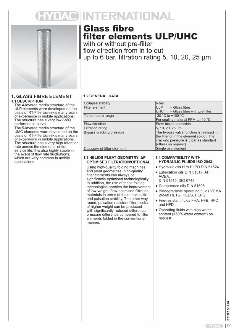
99
E 7.
227.
0/11
.16
Glass fibre filter elements ULP/UHCwith or without pre-filter flow direction from in to out up to 6 bar, filtration rating 5, 10, 20, 25 µm
1. GLASS FIBRE ELEMENT1.1 DESCRIPTION
The 4-layered media structure of the ULP elements were developed on the basis of RT-Filtertechnik’s many years of experience in mobile applications. The structure has a very low Δp/Q performance curve.The 5-layered media structure of the UMC elements were developed on the basis of RT-Filtertechnik’s many years of experience in mobile applications. The structure has a very high retention rate across the elements’ entire service life. It is also highly stable in the event of flow rate fluctuations, which are very common in mobile applications.
1.2 GENERAL DATA
E 7.
227.
0/11
.16
1.3 HELIOS PLEAT GEOMETRY: ΔP OPTIMISED FILTRATION/OPTIONALUsing high-quality folding machines and pleat geometries, high-quality filter elements can always be significantly optimised technologically. In addition, the use of these folding technologies enables the improvement of low-weight, flow-optimised filtration materials in terms of their service life and pulsation stability. The other way round, pulsation resistant filter media of higher weight can be produced with significantly reduced differential pressure difference compared to filter elements folded in the conventional manner.
Collapse stability 6 barFilter element ULP = Glass fibre
UHC = Glass fibre with pre-filterTemperature range -30 °C to +100 °C
For sealing material FPM to -10 °CFlow direction From inside to outsideFiltration rating 5, 10, 20, 25 µmBypass cracking pressure The bypass valve function is realised in
the filter or in the element spigot. The cracking pressure is 3 bar as standard (others on request)
Category of filter element Single use element
1.4 COMPATIBILITY WITH HYDRAULIC FLUIDS ISO 2943
● Hydraulic oils H to HLPD DIN 51524 ● Lubrication oils DIN 51517, API, ACEA, DIN 51515, ISO 6743
● Compressor oils DIN 51506 ● Biodegradable operating fluids VDMA 24568 HETG, HEES, HEPG
● Fire-resistant fluids FHA, HFB, HFC and HFD
● Operating fluids with high water content (>50% water content) on request

100
E 7.
227.
0/11
.16
2. MODEL CODE
0080 D 010 ULP /-VSize 0020, 0045, 0080, 0150, 0250
Type D Pressure filter element
Filtration rating in µm 005, 010, 025
Filter material of element ULP Collapse stability up to 6 bar
Supplementary details V FPM (Viton) seal
2.1 MODEL CODE FOR STANDARD PRESSURE FILTER ELEMENTS(Can be used in the following filters: LFR, LPFR, MDFR)
0600 RMT 010 ULP /-VSize 0600, 0800, 1200
Type R Return line filter element
Filtration rating in µm 005, 010, 025
Filter material of element ULP Collapse stability up to 6 bar
Supplementary details V FPM (Viton) seal
2.3 MODEL CODE FOR RETURN LINE FILTER ELEMENTS RMTR(Can be used in the following filters: RMTR)
0400 R 010 ULP /-VSize 0170, 0230, 0300, 0310, 0400, 0500, 0600, 0800, 1200
Type R Return line filter element
Filtration rating in µm 005, 010, 025
Filter material of element ULP Collapse stability up to 6 bar
Supplementary details V FPM (Viton) seal
2.2 MODEL CODE FOR RETURN LINE FILTER ELEMENTS(Can be used in the following filters: RMER, RPER, RKMR)
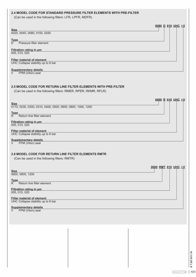
101
E 7.
227.
0/11
.16
0080 D 010 UHC /-VSize 0020, 0045, 0080, 0150, 0250
Type D Pressure filter element
Filtration rating in µm 005, 010, 020
Filter material of element UHC Collapse stability up to 6 bar
Supplementary details V FPM (Viton) seal
2.4 MODEL CODE FOR STANDARD PRESSURE FILTER ELEMENTS WITH PRE-FILTER(Can be used in the following filters: LFR, LPFR, MDFR)
0600 RMT 010 UHC /-VSize 0600, 0800, 1200
Type R Return line filter element
Filtration rating in µm 005, 010, 020
Filter material of element UHC Collapse stability up to 6 bar
Supplementary details V FPM (Viton) seal
2.6 MODEL CODE FOR RETURN LINE FILTER ELEMENTS RMTR(Can be used in the following filters: RMTR)
0400 R 010 UHC /-VSize 0170, 0230, 0300, 0310, 0400, 0500, 0600, 0800, 1000, 1200
Type R Return line filter element
Filtration rating in µm 005, 010, 020
Filter material of element UHC Collapse stability up to 6 bar
Supplementary details V FPM (Viton) seal
2.5 MODEL CODE FOR RETURN LINE FILTER ELEMENTS WITH PRE-FILTER(Can be used in the following filters: RMER, RPER, RKMR, RFLR)

102
E 7.
227.
0/11
.16
3. FILTER CALCULATION / SIZINGThe total pressure drop of a filter at a certain flow rate Q is the sum of the housing ∆p and the element ∆p and is calculated as follows:∆ptotal = ∆phousing + ∆pelement
∆phousing = see housing curve in the relevant filter brochure
∆pelement = Q • SK* • viscosity 1000 30 (* gradient coefficient see Point 4.1)
4.2 CONTAMINATION RETENTION CAPACITY IN GThe contamination retention and particle filtration performance of an element are established in the multipass test to ISO 16889. This procedure with its precisely defined test conditions and a standard test dust (ISO MTD) enables the performance data of different elements to be compared.
Pressure filter element "D"...ULPFilter size 5 µm 10 µm 25 µm0020 1.5 2.61 2.90045 3.4 6.03 6.70080 4.2 7.51 8.40150 5.3 9.45 10.50250 8.5 15.3 17.0
Return line filter element "R"...ULPFilter size 5 µm 10 µm 25 µm0170 12.4 22.3 27.20230 17.4 31.3 38.10300 31.9 57.4 70.00310 27.1 48.8 59.50400 36.9 65.2 79.50500 43.8 78.9 96.20600 85.0 153.0 170.00800 115.0 207.0 230.01200 170.0 306.0 340.0
Pressure filter element "D"...UHCFilter size 5 µm 10 µm 20 µm0020 4.6 6.9 7.80045 10.7 16.1 18.10080 13.4 20.0 22.60150 16.8 25.2 28.40250 27.2 40.8 45.9
Return line filter element "R"...UHCFilter size 5 µm 10 µm 20 µm0170 24.3 36.4 44.40230 31.7 47.6 58.10300 51.8 77.7 94.80310 51.8 77.7 83.30400 60.8 91.2 111.30500 78.0 117.0 142.70600 272.0 408.0 459.00800 368.0 552.0 621.01000 438.0 658.0 739.01200 544.0 816.0 918.0
4. ELEMENT CHARACTERISTICS
4.1 GRADIENT COEFFICIENTS FOR FILTER ELEMENTSThe gradient coefficients in mbar/(l/min) apply to mineral oils with a kinematic viscosity of 30 mm²/s. The pressure drop changes proportionally to the change in viscosity.
Pressure filter element "D"...ULPFilter size 5 µm 10 µm 25 µm0020 32.4 17.6 8.00045 14.2 7.2 2.90080 11.3 5.5 2.20150 6.8 3.3 1.30250 4.2 2.0 0.8
Return line filter element "R"...ULPFilter size 5 µm 10 µm 25 µm0170 3.23 1.70 0.790230 2.39 1.26 0.590300 1.79 0.94 0.440310 1.79 0.94 0.440400 1.37 0.72 0.330500 1.25 0.66 0.310600 0.50 0.25 0.080800 0.40 0.18 0.061200 0.24 0.10 0.03
Pressure filter element "D"...UHCFilter size 5 µm 10 µm 20 µm0020 40.8 22.2 10.60045 18.0 9.0 4.50080 14.2 7.1 3.50150 8.6 4.3 2.00250 5.3 2.6 1.3
Return line filter element "R"...UHCFilter size 5 µm 10 µm 20 µm0170 3.1 1.86 1.020230 2.9 1.38 0.760300 2.0 1.02 0.560310 2.0 1.02 0.560400 1.64 0.78 0.430500 1.51 0.72 0.400600 0.70 0.35 0.150800 0.54 0.26 0.091000 0.35 0.15 0.081200 0.28 0.13 0.06
Others on request!
NOTEThe information in this brochure relates to the operating conditions and applications described. For applications or operating conditions not described, please contact the relevant technical department. All technical details are subject to change without notice.
HYDAC Filtertechnik GmbH Industriegebiet D-66280 Sulzbach/Saar Tel.: 0 68 97 / 509-01 Fax: 0 68 97 / 509-300 Internet: www.hydac.com e-mail: [email protected]
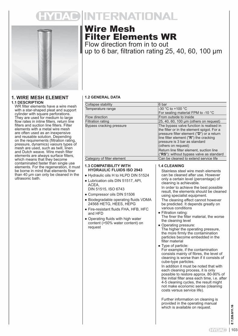
103
E 7.
226.
0/11
.16
Wire Mesh Filter Elements WRFlow direction from in to out up to 6 bar, filtration rating 25, 40, 60, 100 µm
1. WIRE MESH ELEMENT1.1 DESCRIPTION
WR filter elements have a wire mesh with a star-shaped pleat and support cylinder with square perforations. They are used for medium to large flow rates in inline filters, return line filters and suction line filters. Filter elements with a metal wire mesh are often used as an inexpensive and reusable solution. Depending on the requirements (filtration rating, pressure, dynamics) vaiours types of mesh are used, such as twill, linen and Dutch weave. Wire mesh filter elements are always surface filters, which means that they become contaminated faster than single use elements. For the regeneration, it must be borne in mind that elements finer than 40 µm can only be cleaned in the ultrasonic bath.
1.2 GENERAL DATA
E 7.
226.
0/11
.16
1.4 CLEANINGStainless steel wire mesh elements can be cleaned after use. However only a certain level (percentage) of cleaning is achievable.In order to achieve the best possible result, the elements should be cleaned using specialist equipment.The cleaning effect cannot however be predicted. It depends greatly on various conditions
● Filtration rating: The finer the filter material, the worse the cleaning level
● Operating pressure: The higher the operating pressure, the more firmly the contamination particles become embedded in the filter material
● Type of particle: For example, if the contamination consists mainly of fibres, the level of cleaning is worse than if it consists of cube-type particles.In addition it must be noted that with each cleaning process, it is only possible to restore approx. 80-90% of the initial filter area each time, i.e. after 4-5 cleaning cycles, the result might not make economic sense (cleaning costs versus service life).
Further information on cleaning is provided in the operating manual which is available on request.
Collapse stability 6 barTemperature range -30 °C to +100 °C
For sealing material FPM to -10 °CFlow direction From outside to insideFiltration rating 25, 40, 60, 100 µm (others on request)Bypass cracking pressure The bypass valve function is realised in
the filter or in the element spigot. For a pressure filter element ("D") or a return line filter element ("R") the cracking pressure is 3 bar as standard (others on request)Return line filter element, suction line ("RS"): without bypass valve as standard
Category of filter element Can be cleaned to extend service life
1.3 COMPATIBILITY WITH HYDRAULIC FLUIDS ISO 2943
● Hydraulic oils H to HLPD DIN 51524 ● Lubrication oils DIN 51517, API, ACEA, DIN 51515, ISO 6743
● Compressor oils DIN 51506 ● Biodegradable operating fluids VDMA 24568 HETG, HEES, HEPG
● Fire-resistant fluids FHA, HFB, HFC and HFD
● Operating fluids with high water content (>50% water content) on request

104
E 7.
226.
0/11
.16
2. MODEL CODE
0080 D 040 WR /-VSize 0020, 0045, 0080, 0150, 0250
Type D Pressure filter element
Filtration rating in µm 025, 040, 060
Filter material of element WR Collapse stability up to 6 bar
Supplementary details V FKM (Viton) seal
2.1 MODEL CODE FOR PRESSURE FILTER ELEMENTS(Can be used in the following filters: LFR, LPFR, MDFR)
0180 RS 100 WR /-VSize 0100, 0150, 0180, 200, 250
Type RS Return line filter element, suction line filter
Filtration rating in µm 100
Filter material of element WR Collapse stability up to 3 bar
Supplementary details V FKM (Viton) seal
2.3 MODEL CODE FOR RETURN LINE FILTER ELEMENTS, SUCTION LINE FILTER(Can be used in the following filters: SFAR)
0800 R 040 WR /-VSize 0170, 0230, 0300, 0310, 0400, 0500, 0600, 0800, 1000, 1200
Type R Return line filter element
Filtration rating in µm 025, 040, 060
Filter material of element WR Collapse stability up to 6 bar
Supplementary details V FKM (Viton) seal
2.2 MODEL CODE FOR RETURN LINE FILTER ELEMENTS(Can be used in the following filters: RMER; RMTR, RPER, RFLR)
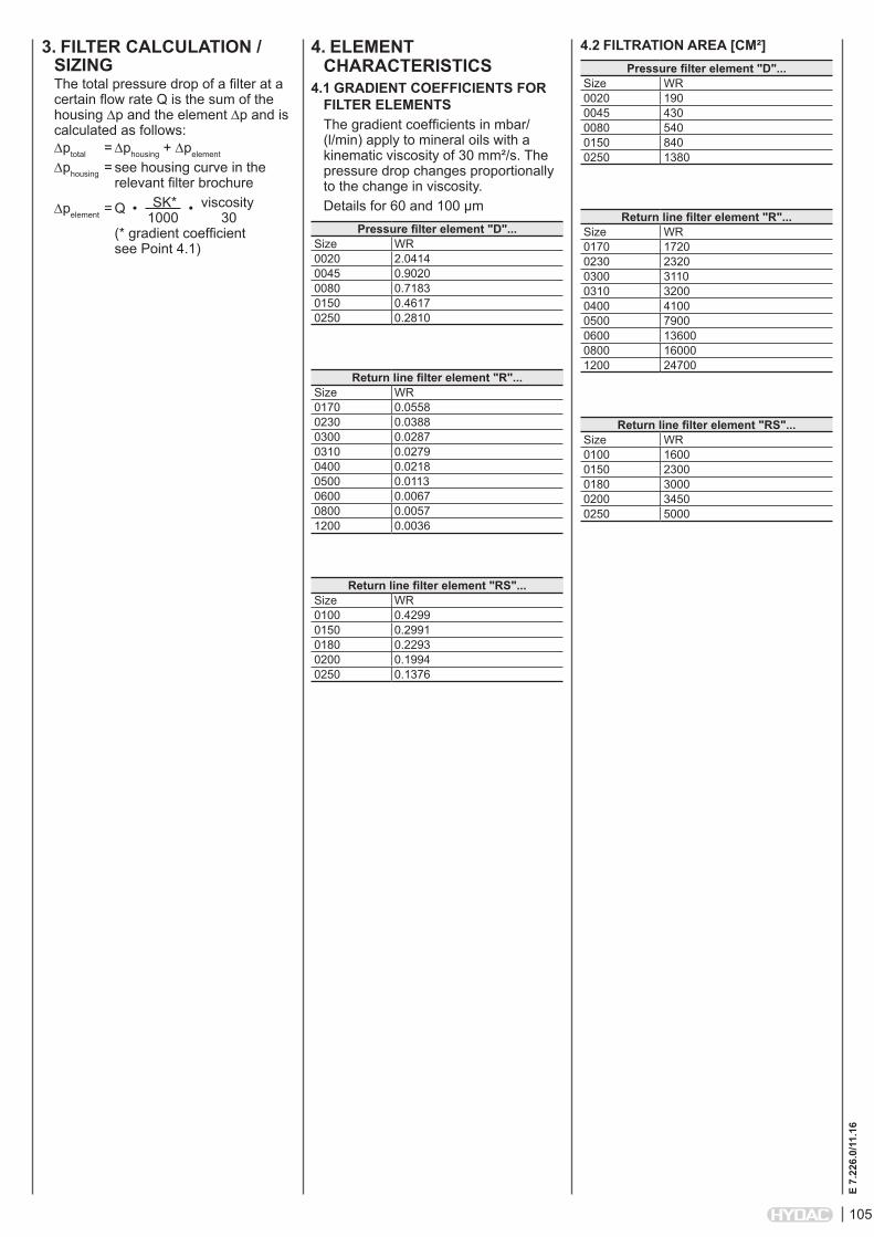
105
E 7.
226.
0/11
.16
3. FILTER CALCULATION / SIZINGThe total pressure drop of a filter at a certain flow rate Q is the sum of the housing ∆p and the element ∆p and is calculated as follows:∆ptotal = ∆phousing + ∆pelement
∆phousing = see housing curve in the relevant filter brochure
∆pelement = Q • SK* • viscosity 1000 30 (* gradient coefficient see Point 4.1)
4.2 FILTRATION AREA [CM²]Pressure filter element "D"...
Size WR0020 1900045 4300080 5400150 8400250 1380
Return line filter element "R"...Size WR0170 17200230 23200300 31100310 32000400 41000500 79000600 136000800 160001200 24700
Return line filter element "RS"...Size WR0100 16000150 23000180 30000200 34500250 5000
4. ELEMENT CHARACTERISTICS
4.1 GRADIENT COEFFICIENTS FOR FILTER ELEMENTSThe gradient coefficients in mbar/(l/min) apply to mineral oils with a kinematic viscosity of 30 mm²/s. The pressure drop changes proportionally to the change in viscosity.Details for 60 and 100 µm
Pressure filter element "D"...Size WR0020 2.04140045 0.90200080 0.71830150 0.46170250 0.2810
Return line filter element "R"...Size WR0170 0.05580230 0.03880300 0.02870310 0.02790400 0.02180500 0.01130600 0.00670800 0.00571200 0.0036
Return line filter element "RS"...Size WR0100 0.42990150 0.29910180 0.22930200 0.19940250 0.1376
106
E 7.
226.
0/11
.16
NOTEThe information in this brochure relates to the operating conditions and applications described. For applications or operating conditions not described, please contact the relevant technical department. All technical details are subject to change without notice.
HYDAC Filtertechnik GmbH Industriegebiet D-66280 Sulzbach/Saar Tel.: 0 68 97 / 509-01 Fax: 0 68 97 / 509-300 Internet: www.hydac.com e-mail: [email protected]
NOTES
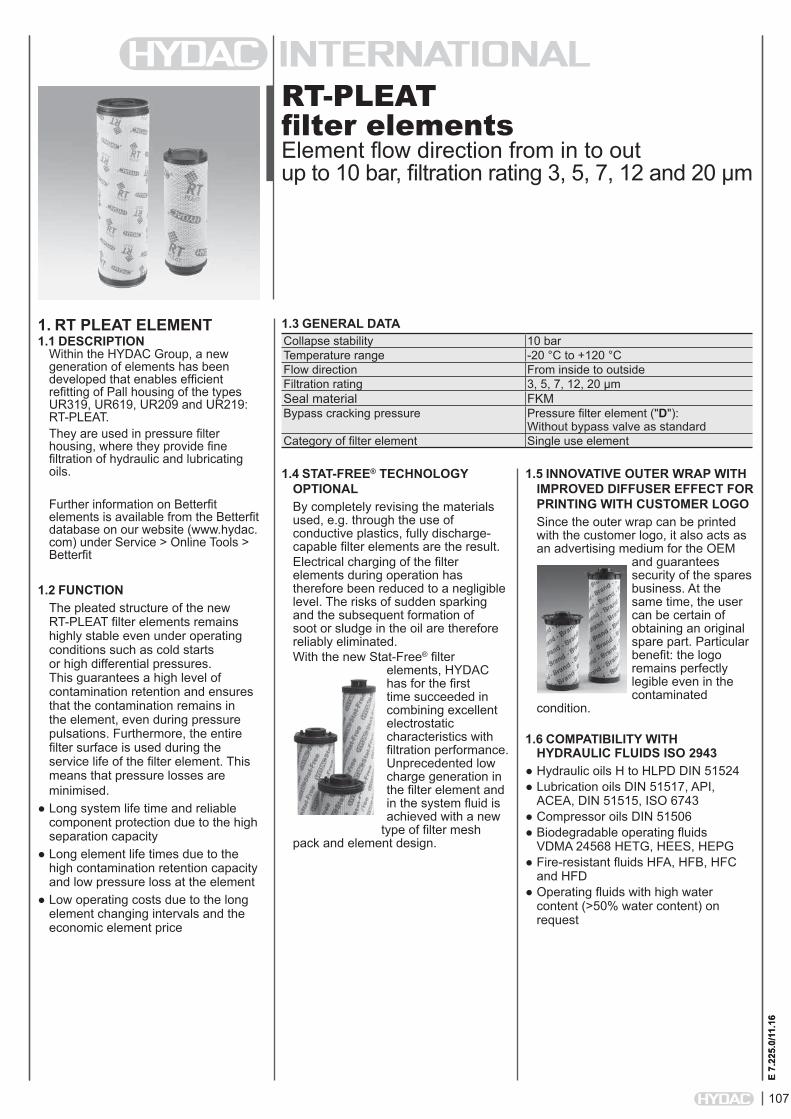
107
E 7.
225.
0/11
.16
RT-PLEAT filter elementsElement flow direction from in to outup to 10 bar, filtration rating 3, 5, 7, 12 and 20 µm
1. RT PLEAT ELEMENT1.1 DESCRIPTION
Within the HYDAC Group, a new generation of elements has been developed that enables efficient refitting of Pall housing of the types UR319, UR619, UR209 and UR219: RT-PLEAT.They are used in pressure filter housing, where they provide fine filtration of hydraulic and lubricating oils.
Further information on Betterfit elements is available from the Betterfit database on our website (www.hydac.com) under Service > Online Tools > Betterfit
1.2 FUNCTIONThe pleated structure of the new RT-PLEAT filter elements remains highly stable even under operating conditions such as cold starts or high differential pressures. This guarantees a high level of contamination retention and ensures that the contamination remains in the element, even during pressure pulsations. Furthermore, the entire filter surface is used during the service life of the filter element. This means that pressure losses are minimised.
● Long system life time and reliable component protection due to the high separation capacity
● Long element life times due to the high contamination retention capacity and low pressure loss at the element
● Low operating costs due to the long element changing intervals and the economic element price
1.3 GENERAL DATA
E 7.
225.
0/11
.16
Collapse stability 10 barTemperature range -20 °C to +120 °CFlow direction From inside to outsideFiltration rating 3, 5, 7, 12, 20 µmSeal material FKMBypass cracking pressure Pressure filter element ("D"):
Without bypass valve as standardCategory of filter element Single use element
1.4 STAT-FREE® TECHNOLOGY OPTIONALBy completely revising the materials used, e.g. through the use of conductive plastics, fully discharge-capable filter elements are the result. Electrical charging of the filter elements during operation has therefore been reduced to a negligible level. The risks of sudden sparking and the subsequent formation of soot or sludge in the oil are therefore reliably eliminated.With the new Stat-Free® filter
elements, HYDAC has for the first time succeeded in combining excellent electrostatic characteristics with filtration performance. Unprecedented low charge generation in the filter element and in the system fluid is achieved with a new
type of filter mesh pack and element design.
1.5 INNOVATIVE OUTER WRAP WITH IMPROVED DIFFUSER EFFECT FOR PRINTING WITH CUSTOMER LOGOSince the outer wrap can be printed with the customer logo, it also acts as an advertising medium for the OEM
and guarantees security of the spares business. At the same time, the user can be certain of obtaining an original spare part. Particular benefit: the logo remains perfectly legible even in the contaminated
condition.
1.6 COMPATIBILITY WITH HYDRAULIC FLUIDS ISO 2943
● Hydraulic oils H to HLPD DIN 51524● Lubrication oils DIN 51517, API,
ACEA, DIN 51515, ISO 6743● Compressor oils DIN 51506● Biodegradable operating fluids
VDMA 24568 HETG, HEES, HEPG● Fire-resistant fluids HFA, HFB, HFC
and HFD ● Operating fluids with high water
content (>50% water content) on request
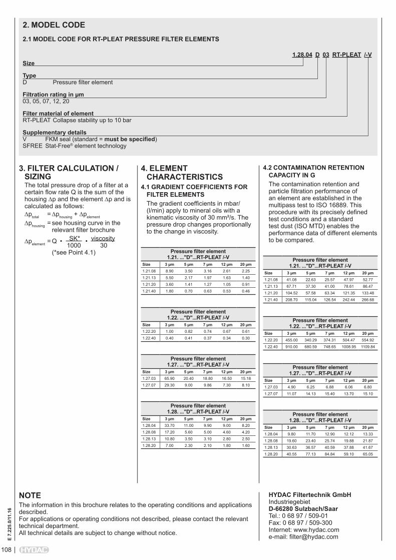
108
E 7.
225.
0/11
.16
2. MODEL CODE
1.28.04 D 03 RT-PLEAT /-VSize
Type D Pressure filter element
Filtration rating in µm 03, 05, 07, 12, 20
Filter material of element RT-PLEAT Collapse stability up to 10 bar
Supplementary details V FKM seal (standard = must be specified) SFREE Stat-Free® element technology
2.1 MODEL CODE FOR RT-PLEAT PRESSURE FILTER ELEMENTS
3. FILTER CALCULATION / SIZINGThe total pressure drop of a filter at a certain flow rate Q is the sum of the housing ∆p and the element ∆p and is calculated as follows:∆ptotal = ∆phousing + ∆pelement
∆phousing = see housing curve in the relevant filter brochure
∆pelement = Q • SK* • viscosity 1000 30 (*see Point 4.1)
4. ELEMENT CHARACTERISTICS
4.1 GRADIENT COEFFICIENTS FOR FILTER ELEMENTSThe gradient coefficients in mbar/(l/min) apply to mineral oils with a kinematic viscosity of 30 mm²/s. The pressure drop changes proportionally to the change in viscosity.
Pressure filter element 1.21. ..."D"...RT-PLEAT /-V
Size 3 µm 5 µm 7 µm 12 µm 20 µm1.21.08 8.90 3.50 3.16 2.61 2.25
1.21.13 5.50 2.17 1.97 1.63 1.40
1.21.20 3.60 1.41 1.27 1.05 0.91
1.21.40 1.80 0.70 0.63 0.53 0.46
Pressure filter element 1.22. ..."D"...RT-PLEAT /-V
Size 3 µm 5 µm 7 µm 12 µm 20 µm1.22.20 1.00 0.82 0.74 0.67 0.61
1.22.40 0.40 0.41 0.37 0.34 0.30
Pressure filter element 1.27. ..."D"...RT-PLEAT /-V
Size 3 µm 5 µm 7 µm 12 µm 20 µm1.27.03 65.90 20.40 18.80 16.50 15.18
1.27.07 29.30 9.00 9.86 7.30 8.10
Pressure filter element 1.28. ..."D"...RT-PLEAT /-V
Size 3 µm 5 µm 7 µm 12 µm 20 µm1.28.04 33.70 11.00 9.90 9.00 8.20
1.28.08 17.20 5.60 5.00 4.60 4.20
1.28.13 10.80 3.50 3.10 2.80 2.50
1.28.20 7.00 2.30 2.10 1.80 1.60
NOTEThe information in this brochure relates to the operating conditions and applications described. For applications or operating conditions not described, please contact the relevant technical department. All technical details are subject to change without notice.
HYDAC Filtertechnik GmbH Industriegebiet D-66280 Sulzbach/Saar Tel.: 0 68 97 / 509-01 Fax: 0 68 97 / 509-300 Internet: www.hydac.com e-mail: [email protected]
4.2 CONTAMINATION RETENTION CAPACITY IN GThe contamination retention and particle filtration performance of an element are established in the multipass test to ISO 16889. This procedure with its precisely defined test conditions and a standard test dust (ISO MTD) enables the performance data of different elements to be compared.
Pressure filter element 1.21. ..."D"...RT-PLEAT /-V
Size 3 µm 5 µm 7 µm 12 µm 20 µm1.21.08 41.08 22.63 25.57 47.97 52.77
1.21.13 67.71 37.30 41.00 78.61 86.47
1.21.20 104.52 57.58 63.34 121.35 133.48
1.21.40 208.70 115.04 126.54 242.44 266.68
Pressure filter element 1.22. ..."D"...RT-PLEAT /-V
Size 3 µm 5 µm 7 µm 12 µm 20 µm1.22.20 455.00 340.29 374.31 504.47 554.92
1.22.40 910.00 680.59 748.65 1008.95 1109.84
Pressure filter element 1.27. ..."D"...RT-PLEAT /-V
Size 3 µm 5 µm 7 µm 12 µm 20 µm1.27.03 4.90 6.25 6.88 6.06 6.80
1.27.07 11.07 14.13 15.40 13.70 15.10
Pressure filter element 1.28. ..."D"...RT-PLEAT /-V
Size 3 µm 5 µm 7 µm 12 µm 20 µm1.28.04 9.80 11.70 12.90 12.12 13.33
1.28.08 19.60 23.40 25.74 19.88 21.87
1.28.13 30.63 36.57 40.59 37.88 41.67
1.28.20 40.55 77.13 84.84 59.10 65.05
The HYDAC Betterfit Range With our Investment, You Can't Lose.
E 7.
208.
2/11
.16
109
E 7.
208.
2/11
.16
The HYDAC Betterfit Range: The Royal Flush in Filter Elements.The Best Combination. Every Time. On Paper and in Practice. With HYDAC and the HYDAC Betterfit Range you hold all the aces when it comes to conditioning your fluids:
Global Presence. HYDAC forges close links with its customers by providing engineering advice and fluid engineering in over 45 international subsidiaries and over 500 distributors and service partners worldwide.
Specialist expertise. HYDAC has developed expertise in the research, development and production of filter housings, filter systems and filter elements over many decades.
Industry competence. HYDAC industry competence forged through close cooperation with the most exacting international clients in almost all industries in the world.
Complete range. HYDAC filter elements provide a comprehensive range to suit all applications and also almost all competitor filters. Our customer-focused service package is included, ranging from specialist advice to availability at short notice.
Quality from the ground up. In the HYDAC Fluid Care Center, which is our own state-of-the-art industrial laboratory for basic research, functionality and quality testing as well as application-specific development, we explore the most efficient fluid technology solutions. This results in high-end quality filters and elements with maximum efficiency.
Strongest link in the chain. As a system partner with wide-ranging industrial experience, HYDAC does its utmost to ensure each filter element is one of the most efficient links in the functionality chain of fluid technology systems. HYDAC therefore guarantees the greatest possible component protection for the longest possible service life.
Better is better than good enough. The HYDAC Betterfit range combines the best ideas and the best in fluid engineering – filter elements which stand up to every comparison and every challenge.
110
E 7.
208.
2/11
.16
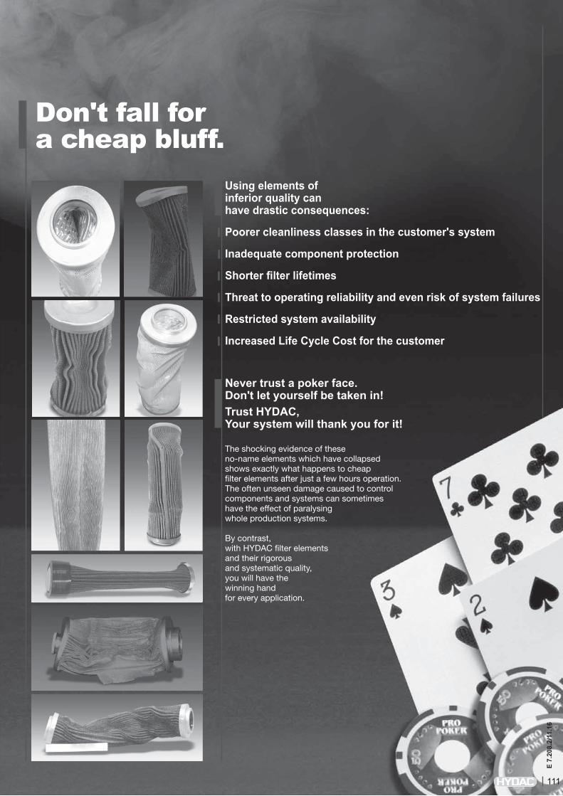
Using elements of inferior quality can have drastic consequences:
Poorer cleanliness classes in the customer's system
Inadequate component protection
Shorter filter lifetimes
Threat to operating reliability and even risk of system failures
Restricted system availability
Increased Life Cycle Cost for the customer
Never trust a poker face. Don't let yourself be taken in! Trust HYDAC, Your system will thank you for it! The shocking evidence of these no-name elements which have collapsed shows exactly what happens to cheap filter elements after just a few hours operation. The often unseen damage caused to control components and systems can sometimes have the effect of paralysing whole production systems. By contrast, with HYDAC filter elements and their rigorous and systematic quality, you will have the winning handfor every application.
Don't fall for a cheap bluff.
111
E 7.
208.
2/11
.16

BETAMICRON®4 Decades of experience and ongoing further development in the field of hydraulic and lubrication oil filtration have given HYDAC the technological edge in top quality filter element technology.The high performance Betamicron®4 is the predominant material used in the Betterfit element product range. This innovative glass fibre media will convince you with its exceptionally high contamination retention capacities, excellent filtration efficiency and optimized ∆p/Q characteristics. Particular customer benefits of HYDAC filter elements:Energy cost savings thanks to particularly low pressure dropsHigh quality component protection and long system life due to excellent filtration efficiencyLong service life and low operating costs due to particularly high contamination retention capacitiesHigh degree of operating reliability because of compact and robust construction
EFFICIENCYGlobal and yet local.45 overseas companies and over 500 sales and service partners provide a worldwide presence on the ground. We provide efficient support on demand.
TOTAL CLEANLINESS And your system will thank you for it.
Here you are guaranteed to find the right element.The HYDAC Betterfit range covers a wide variety of replacement elements in the dimensions used by competitors, particularly all well-known filter element manufacturers. Our Betterfit elements are made predominantly from the tried-and-tested Betamicron4 element technology (other materials, such as synthetic fibre or wire mesh are also available). Put your money on genuine quality equipment and opt for Hydac replacement elements – your system will thank you for it!By using our Betterfit elements you will benefit from the whole Hydac service package – from oil sampling to oil analysis. This also includes identifying the source of faults and designing filtration concepts. Hydac supports you at every stage and in all aspects of fluid service. Just as our motto says "With our investment, you can't lose" we will take care of your system, leaving you to concentrate fully on your core competence.
Steady expansion of the Betterfit range.Since launching the Betterfit range the number of replacement filter elements has increased daily. We respond to your request. If the required element is not yet available, we will endeavour to add it to the Betterfit product range as quickly as possible once we have examined the design. Today there are approximately 23,000 replacement elements in the Betterfit line of elements and the number is growing day by day.
FLUID MANAGEMENTWith HYDAC, your fluid is in safe handsWe know your fluid and welcome the opportunity to help you reduce the burden of fluid service. You will see for yourself the clear benefit of having a hydraulic or lubrication system that works perfectly, leaving you to concentrate fully on your specialism. Entrust us with your fluid and benefit from our Fluid Engineering package since this ensures:
A long system life thanks to better component protection.
A definite cost saving due to reduced operating and downtime costs.
TECHNICAL SUPPORTSkilled advisors in the regional offices and overseas subsidiaries.
ONE FOR ALLAll from one supplier.HYDAC can supply you with the whole spectrum of products including outstanding Fluid Service. Specifically in the area of filtration, we can supply you with every filter element used in your production processes from our Betterfit range - just tell us your filter cartridge requirement and you will receive the complete package from one supplier. In short: we take care of your filtration needs whilst you concentrate fully on your core competence.
CLEANLINESSSystem cleanliness assured by professionalism and quality.
Betterfit Range
B-E-T-T-E-R-F-I-T Better for quality and efficiency.
112
E 7.
208.
2/11
.16
TREND: SYSTEM EXPERTISESub-systems and systems.HYDAC is not only a component specialist, but also has decades of experience in power unit and system engineering. The filter component is therefore never viewed in isolation, but always as an important part of the whole system. This practice is followed through to the complete system!With this wealth of expertise in applications and systems, HYDAC automatically sees its individual components, such as filters and filter elements, in conjunction with the whole system and understands how they can best be configured to suit the particular system requirements.
INTELLIGENT FLUID SERVICEBy making use of HYDAC fluid service specialists.In fluid service, too, you can benefit from decades of experience and development. How HYDAC's excellent fluid service benefits you:On-site diagnostics with our laboratory vehicles Specialist staff available on demand Lower costs thanks to professional oil sample analysis, monitoring and support (condition-based maintenance)Lower maintenance and spare part costsIncreased operating reliability due to fewer breakdowns
Within the framework of Fluid Engineering HYDAC guarantees you the right filter and the right filter element in the right location – because for HYDAC, this is not just wishful thinking, but an everyday reality.
And fits all housings, fluids and cleanliness classes.
113
E 7.
208.
2/11
.16

Don't gamble with your components. Our advice: Invest in genuine quality!The many years' development in the area of element technology is your guarantee of first class quality in Hydac filter elements and this applies equally to the Betterfit range.
By using Betterfit elements, the Life Cycle Cost of your system will be optimized, thereby reducing the total costs of the machine or a component, from procurement right through to disposal. Reducing these costs is one of the megatrends pursued by large-scale end users in machine building.
Leading automotive manufacturers demand, for example, authoritative data on the Life Cycle Cost and the values derived from it – e.g. for machine tools for 10 years life, for presses even up to 30 years life. New investments by machinery manufacturers are decided on the basis of the machine prices and the Life Cycle Cost calculation provided.
Cost progression during the whole life cycle of the machine / system
The winners in terms of system properties
114
E 7.
208.
2/11
.16
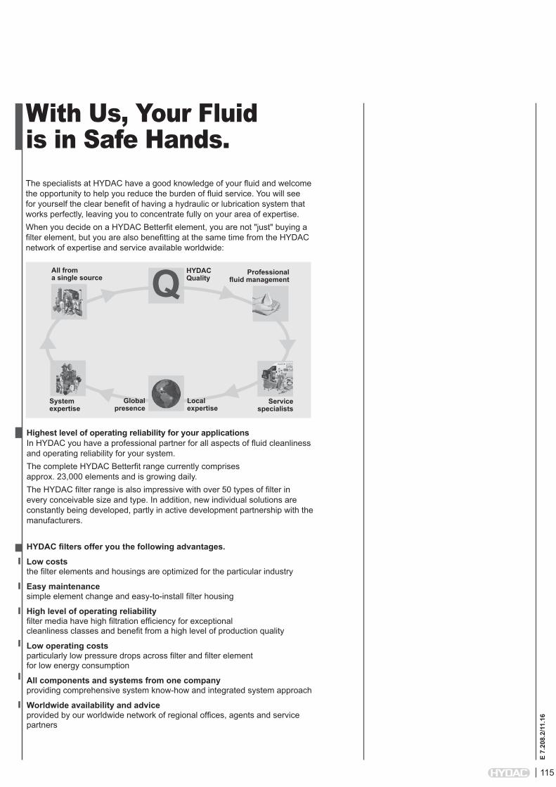
With Us, Your Fluid is in Safe Hands.
Highest level of operating reliability for your applicationsIn HYDAC you have a professional partner for all aspects of fluid cleanliness and operating reliability for your system.The complete HYDAC Betterfit range currently comprises approx. 23,000 elements and is growing daily.The HYDAC filter range is also impressive with over 50 types of filter in every conceivable size and type. In addition, new individual solutions are constantly being developed, partly in active development partnership with the manufacturers.
HYDAC filters offer you the following advantages.
Low coststhe filter elements and housings are optimized for the particular industry
Easy maintenancesimple element change and easy-to-install filter housing
High level of operating reliabilityfilter media have high filtration efficiency for exceptionalcleanliness classes and benefit from a high level of production quality
Low operating costsparticularly low pressure drops across filter and filter elementfor low energy consumption
All components and systems from one companyproviding comprehensive system know-how and integrated system approach
Worldwide availability and adviceprovided by our worldwide network of regional offices, agents and service partners
HYDACQuality
All froma single source
Systemexpertise
Professionalfluid management
Servicespecialists
Q
The specialists at HYDAC have a good knowledge of your fluid and welcome the opportunity to help you reduce the burden of fluid service. You will see for yourself the clear benefit of having a hydraulic or lubrication system that works perfectly, leaving you to concentrate fully on your area of expertise. When you decide on a HYDAC Betterfit element, you are not "just" buying a filter element, but you are also benefitting at the same time from the HYDAC network of expertise and service available worldwide:
Local expertise
Globalpresence
115
E 7.
208.
2/11
.16
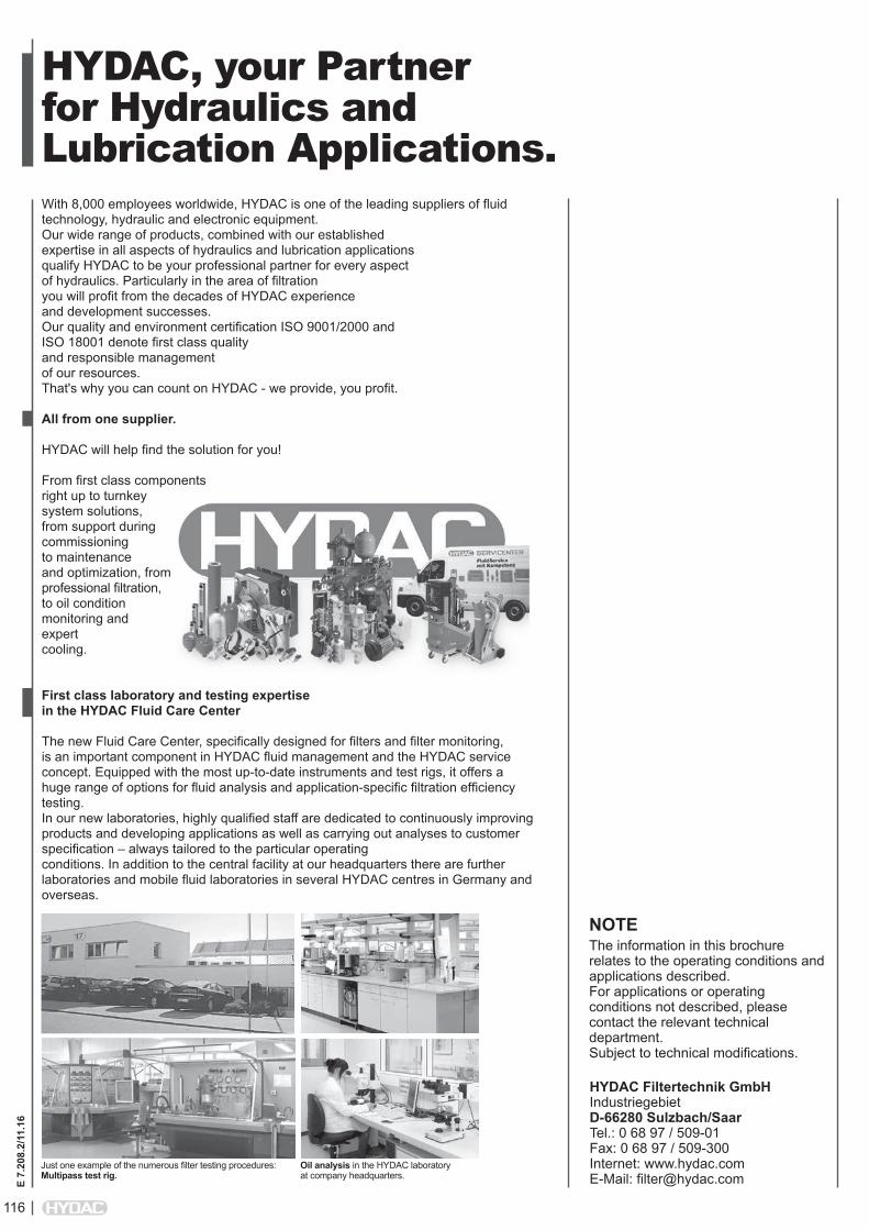
HYDAC, your Partner for Hydraulics andLubrication Applications.With 8,000 employees worldwide, HYDAC is one of the leading suppliers of fluid technology, hydraulic and electronic equipment.Our wide range of products, combined with our established expertise in all aspects of hydraulics and lubrication applicationsqualify HYDAC to be your professional partner for every aspectof hydraulics. Particularly in the area of filtrationyou will profit from the decades of HYDAC experienceand development successes.Our quality and environment certification ISO 9001/2000 andISO 18001 denote first class qualityand responsible management of our resources. That's why you can count on HYDAC - we provide, you profit.
All from one supplier.
HYDAC will help find the solution for you!
From first class componentsright up to turnkeysystem solutions,from support duringcommissioningto maintenanceand optimization, fromprofessional filtration, to oil conditionmonitoring and expert cooling.
First class laboratory and testing expertise in the HYDAC Fluid Care Center
The new Fluid Care Center, specifically designed for filters and filter monitoring, is an important component in HYDAC fluid management and the HYDAC service concept. Equipped with the most up-to-date instruments and test rigs, it offers a huge range of options for fluid analysis and application-specific filtration efficiency testing.In our new laboratories, highly qualified staff are dedicated to continuously improving products and developing applications as well as carrying out analyses to customer specification – always tailored to the particular operating conditions. In addition to the central facility at our headquarters there are further laboratories and mobile fluid laboratories in several HYDAC centres in Germany and overseas.
Just one example of the numerous filter testing procedures:Multipass test rig.
Oil analysis in the HYDAC laboratory at company headquarters.
NOTEThe information in this brochure relates to the operating conditions and applications described. For applications or operating conditions not described, please contact the relevant technical department. Subject to technical modifications.
HYDAC Filtertechnik GmbH Industriegebiet D-66280 Sulzbach/Saar Tel.: 0 68 97 / 509-01 Fax: 0 68 97 / 509-300 Internet: www.hydac.com E-Mail: [email protected]
116
E 7.
208.
2/11
.16