innovative composite steel-timber floors with
TRANSCRIPT

This is a repository copy of Innovative composite steel-timber floors with prefabricated modular components.
White Rose Research Online URL for this paper:http://eprints.whiterose.ac.uk/109977/
Version: Accepted Version
Article:
Loss, C. and Davison, B. (2017) Innovative composite steel-timber floors with prefabricated modular components. Engineering Structures, 132. pp. 695-713. ISSN 0141-0296
https://doi.org/10.1016/j.engstruct.2016.11.062
[email protected]://eprints.whiterose.ac.uk/
Reuse
This article is distributed under the terms of the Creative Commons Attribution-NonCommercial-NoDerivs (CC BY-NC-ND) licence. This licence only allows you to download this work and share it with others as long as you credit the authors, but you can’t change the article in any way or use it commercially. More information and the full terms of the licence here: https://creativecommons.org/licenses/
Takedown
If you consider content in White Rose Research Online to be in breach of UK law, please notify us by emailing [email protected] including the URL of the record and the reason for the withdrawal request.
1
Innovative Composite Steel-Timber Floors with Prefabricated Modular Components 1
Cristiano Loss*, Buick Davison** 2
*Department of Civil, Environmental and Mechanical Engineering, University of Trento, Italy 3
** Department of Civil and Structural Engineering, University of Sheffield, United Kingdom 4
Corresponding author at Department of Civil, Environmental and Mechanical Engineering, University of Trento, 5
77 Via Mesiano 38123, Trento, Italy. Phone: +39 0461 282556 6
E-mail address: [email protected] 7
Abstract 8
An innovative steel-timber composite floor for use in multi-storey residential buildings is presented. The research 9
demonstrates the potential of these steel-timber composite systems in terms of bearing capacity, stiffness and method of 10
construction. Such engineered solutions should prove to be sustainable since they combine recyclable materials in the 11
most effective way. The floors consist of prefabricated ultralight modular components, with a Cross-Laminated Timber 12
(CLT) slab, joined together and to the main structural system using only bolts and screws. Two novel floor solutions are 13
presented, along with the results of experimental tests on the flexural behaviour of their modular components. Bending 14
tests have been performed considering two different methods of loading and constraints. Each prefabricated modular 15
component uses a special arrangement of steel-timber connections to join a CLT panel to two customized cold-formed 16
steel beams. Specifically, the first proposed composite system is assembled using mechanical connectors whereas the 17
second involves the use of epoxy-based resin. In the paper, a FEM model is provided in order to extend this study to 18
other steel-timber composite floor solutions. In addition, the paper contains the design model to be used in 19
dimensioning the developed systems according to the state of the art of composite structures. 20
Keywords: Slim floors; Composite floors; Steel-timber connections; Prefabrication; Modular components; Flexural 21
behavior; Hybrid solutions; Cross-laminated timber; Sustainability; Green design; 22
1. Introduction 23
As part of a process of sustainable development, in the last few years there has been a growing interest in reducing the 24
resources and materials used in building construction, as well as in limiting both the energy consumed during the whole 25
building lifecycle and the related carbon dioxide emissions (CO2) into the atmosphere. Innovative structural systems 26
combine different materials, structural elements, and construction detailing as well as smart construction techniques in a 27
way that fulfills specific performance criteria and contributes to a more sustainable built environment [1,2,3]. The 28
combination of materials in composite construction systems is a way to minimize the use of resources, therefore 29
reducing the environmental impact of the building construction process. In addition, composite systems commonly 30
provide overall performance higher than the sum of their individual components [4]. The literature shows a wide variety 31
2
of composite systems which commonly includes the combination of steel with concrete, timber with concrete, timber 32
with timber, steel with timber or other less common mixes of materials. 33
The most usual and widespread use of composite solutions is for the realization of floors or slabs. Composite floors are 34
commonly built by joining two or more materials to form a collection of T-shaped coupled beams. In general, the 35
composite technique is characterized by the connection systems used in forming the floors and the type of materials 36
combined. Under flexural gravity loading, the upper element works in compression whereas the bottom element is 37
loaded in tension. The connections transfer the shear forces between elements and keep them continuously tied along 38
their extensions. Much research on composite steel-concrete and timber-concrete floors has been done in the past. 39
Particularly, great effort has been devoted to the development of connections to be used in composite systems as well as 40
in studying the effects of long-term loads on their effective behavior. The literature on steel-concrete and timber-41
concrete floors shows an incredible number of solutions available. Works dealing with the implementation of Timber-42
Concrete Composite (TCC) floors include, but are not limited to: [5], [6], [7] and [8]. For a brief state of the art on the 43
TCC floors, we recommend [9]. We point out here that composite timber-concrete floors are very effective solutions for 44
the rehabilitation and strengthening of existing buildings, as demonstrated in [10,11] and [12]. 45
With specific reference to composite steel-concrete floors, an increasing amount of research has been performed over 46
the last century in response to technological development. A remarkable number of documents is available, with a 47
European code [13] specifically dedicated to the design of such composite solutions. The use of composite steel-48
concrete floors is very common with a wide range of construction applications, ranging from new residential buildings, 49
to open-space structures and to skyscrapers and bridges [14–16]. 50
Although composite concrete-based floors have become very common technologies, the use of non-renewable 51
resources, the high demand of energy for production and transportation and the difficult recycling process impact on 52
their sustainability. Possible other inconveniences are the required curing time, which sometimes can complicate on-site 53
construction; the inherent self-weight of the structural components, which typically affects the costs of transportation; 54
the limited number of prefabricated solutions currently available [17]. As ‘dry’ alternatives to the above-mentioned 55
concrete-based traditional solutions, more recently timber-timber and steel-timber composite solutions have attracted 56
more attention. The idea is to replace concrete slabs with innovative engineered wood products such as timber panels 57
made of Cross-Laminated Timber (CLT) or Laminated Veneer Lumber (LVL). To the authors’ best knowledge, very 58
few publications address the issue of the composite timber-timber and steel-timber floor systems, as do for example 59
[18–20]. 60
The purpose of this paper is to discuss two innovative composite steel-timber solutions for residential floors of the next 61
generation of multi-storey buildings [21]. This article introduces research work on modular prefabricated composite 62
3
steel-timber floors made by combining CLT panels with customized cold-formed steel beams. The main challenge of 63
this work was to develop a composite system which satisfies several strict requirements in terms of lightness, 64
prefabrication, modularity, assembly method, sustainability, on-site installation, structural performance, and related 65
manufacturing costs. In this composite system, the combination of steel and wood offers benefits in terms of 66
construction process, as well as off-site production of the structural components in a factory. Based on the rational use 67
of steel and timber, the implementation of composite floor components offers advantages, such as limiting their self-68
weight, and therefore, seismic action and the gravity loads transferred to the foundations; simplifying the execution on-69
site reducing construction time and the related costs; and finally increasing the sustainability of the final construction 70
system, thanks to the use of recyclable and natural materials and to the ability to deconstruct and reuse the structural 71
components. As the final product is a prefabricated standardised structural component suitable for dry construction, it 72
will be possible to rapidly respond to the current housing demand. These floor solutions support the objective of 73
sustainability by reducing the use of resources, therefore, lowering the embodied environmental impact of buildings. 74
This paper provides design details of these novel steel-timber composite solutions for floors and gives a comprehensive 75
introduction to their design. The work provides an overview of the next generation of composite floors made by 76
combining engineered wooden and steel products. The remainder of the paper is organized in six Sections. Section 2 77
describes two innovative hybrid steel-timber solutions to develop composite floors. Experimental tests on prototypes of 78
floors and the data measured are presented in Section 3. Section 4 discusses the FEM model developed to numerically 79
study composite steel-timber systems. In addition, recommendations are made for the model implementation. The 80
proposed design procedure is discussed in Section 5. Finally, Section 6 summarizes the results of this work and draws 81
conclusions. 82
83
2. Innovative steel-timber composite components for residential floors 84
The composite steel-timber technology presented in this paper is engineered to obtain prefabricated modular floor 85
components with excellent structural and non-structural performance. The construction components have been designed 86
paying particular attention to sustainability. Fig. 1 gives the details of the prototypes of floor components, including 87
particulars of the steel and timber elements, cross-section description and both the type and arrangement of connections. 88
These novel solutions are realized by combining a very slim CLT panel with two custom-made steel beams equipped 89
with special parts to quickly join them using connections in steel-to-timber shear configuration. Each mounted floor 90
component is symmetrical in the two main directions and the self-weight is less than 0.5 kN/m2. 91
4
Fig. 1. Prototypes of innovative modular prefabricated floor components developed using a particular steel-timber 92
composite technology. 93
With reference to the construction system depicted in Fig. 2, the modular composite steel-timber components can be 94
quickly joined to a ‘steel frame’ structural system using only bolts at the ends of beams, and self-tapping fully-threaded 95
screws along the panel perimeter, therefore permitting the building processes to take place even under unfavorable 96
climate conditions. Without loss of generality, we have considered dimensions of a frame for a common residential 97
building erected in Italy. Nevertheless, modular floor elements could be also included within other construction types, 98
e.g. timber frame or massive wall panel systems. 99
5
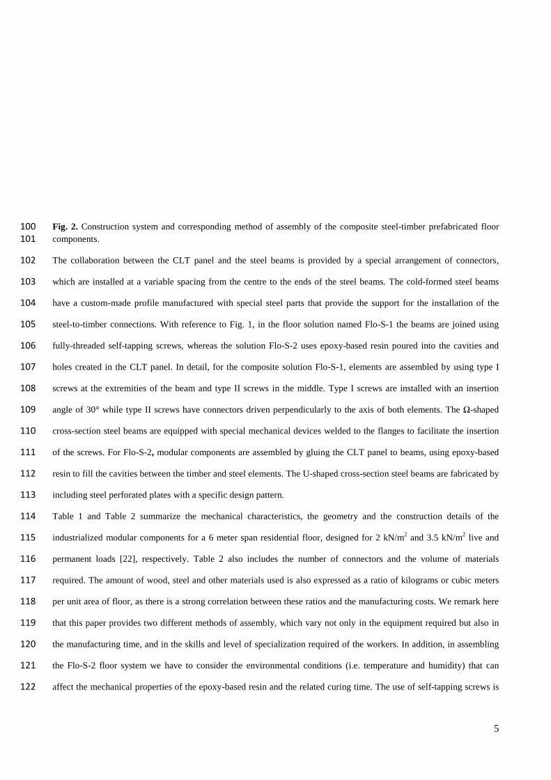
Fig. 2. Construction system and corresponding method of assembly of the composite steel-timber prefabricated floor 100
components. 101
The collaboration between the CLT panel and the steel beams is provided by a special arrangement of connectors, 102
which are installed at a variable spacing from the centre to the ends of the steel beams. The cold-formed steel beams 103
have a custom-made profile manufactured with special steel parts that provide the support for the installation of the 104
steel-to-timber connections. With reference to Fig. 1, in the floor solution named Flo-S-1 the beams are joined using 105
fully-threaded self-tapping screws, whereas the solution Flo-S-2 uses epoxy-based resin poured into the cavities and 106
holes created in the CLT panel. In detail, for the composite solution Flo-S-1, elements are assembled by using type I 107
screws at the extremities of the beam and type II screws in the middle. Type I screws are installed with an insertion 108
angle of 30° while type II screws have connectors driven perpendicularly to the axis of both elements. The Ω-shaped 109
cross-section steel beams are equipped with special mechanical devices welded to the flanges to facilitate the insertion 110
of the screws. For Flo-S-2, modular components are assembled by gluing the CLT panel to beams, using epoxy-based 111
resin to fill the cavities between the timber and steel elements. The U-shaped cross-section steel beams are fabricated by 112
including steel perforated plates with a specific design pattern. 113
Table 1 and Table 2 summarize the mechanical characteristics, the geometry and the construction details of the 114
industrialized modular components for a 6 meter span residential floor, designed for 2 kN/m2 and 3.5 kN/m2 live and 115
permanent loads [22], respectively. Table 2 also includes the number of connectors and the volume of materials 116
required. The amount of wood, steel and other materials used is also expressed as a ratio of kilograms or cubic meters 117
per unit area of floor, as there is a strong correlation between these ratios and the manufacturing costs. We remark here 118
that this paper provides two different methods of assembly, which vary not only in the equipment required but also in 119
the manufacturing time, and in the skills and level of specialization required of the workers. In addition, in assembling 120
the Flo-S-2 floor system we have to consider the environmental conditions (i.e. temperature and humidity) that can 121
affect the mechanical properties of the epoxy-based resin and the related curing time. The use of self-tapping screws is 122
6
less sensitive to the environmental conditions. However, particular attention must be paid in driving the screws, 123
following the guidelines provided by producers and using screwdrivers with a torque limiting device. 124
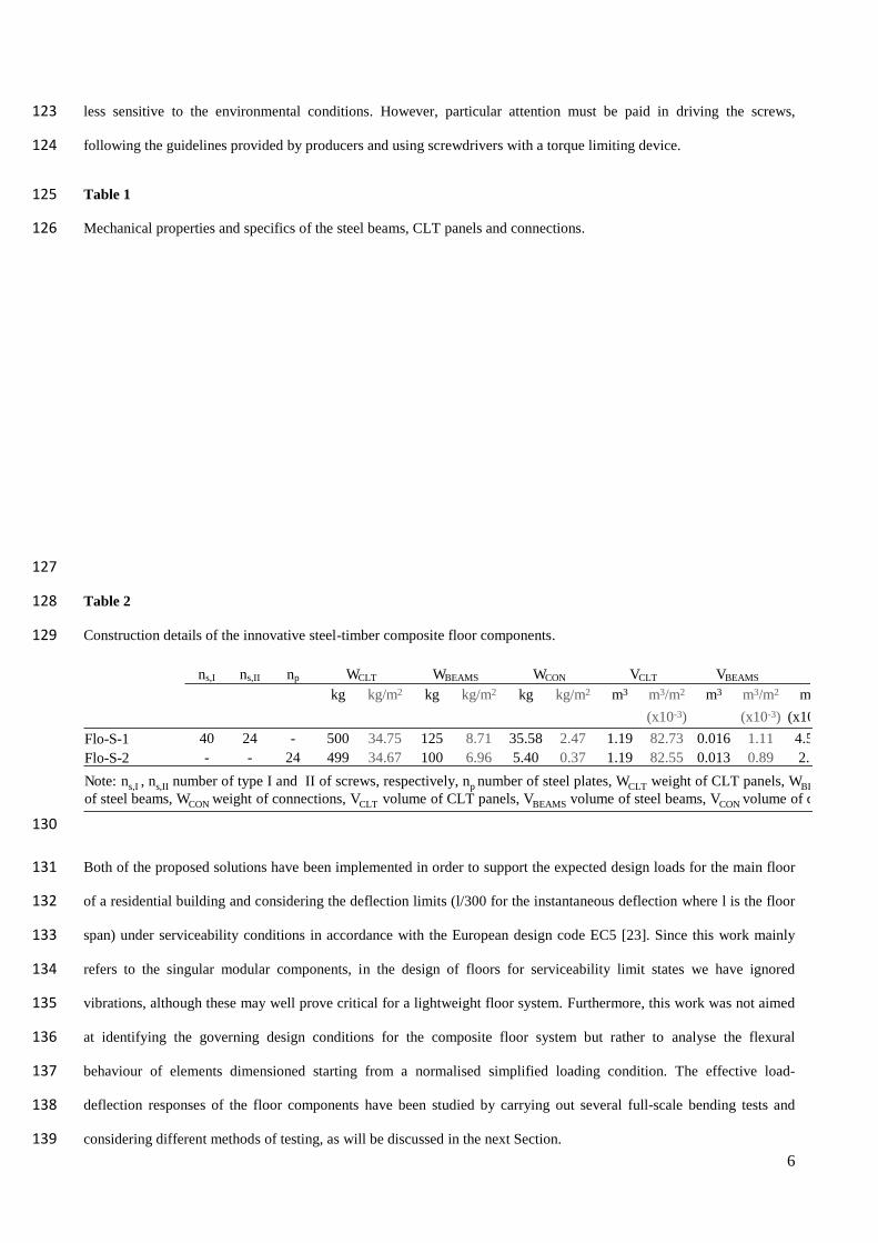
Table 1 125
Mechanical properties and specifics of the steel beams, CLT panels and connections. 126
127
Table 2 128
Construction details of the innovative steel-timber composite floor components. 129
130
Both of the proposed solutions have been implemented in order to support the expected design loads for the main floor 131
of a residential building and considering the deflection limits (l/300 for the instantaneous deflection where l is the floor 132
span) under serviceability conditions in accordance with the European design code EC5 [23]. Since this work mainly 133
refers to the singular modular components, in the design of floors for serviceability limit states we have ignored 134
vibrations, although these may well prove critical for a lightweight floor system. Furthermore, this work was not aimed 135
at identifying the governing design conditions for the composite floor system but rather to analyse the flexural 136
behaviour of elements dimensioned starting from a normalised simplified loading condition. The effective load-137
deflection responses of the floor components have been studied by carrying out several full-scale bending tests and 138
considering different methods of testing, as will be discussed in the next Section. 139
ns,I ns,II np WCLT WBEAMS WCON VCLT VBEAMS
kg kg/m2 kg kg/m2 kg kg/m2 m3 m3/m2 m3 m3/m2 m3
(x10-3) (x10-3) (x10
Flo-S-1 40 24 - 500 34.75 125 8.71 35.58 2.47 1.19 82.73 0.016 1.11 4.52Flo-S-2 - - 24 499 34.67 100 6.96 5.40 0.37 1.19 82.55 0.013 0.89 2.7
Note: ns,I , ns,II numberof type I and II of screws, respectively, np numberof steel plates, WCLT weightof CLT panels, WBEof steel beams, WCON weightof connections, VCLT volumeof CLT panels, VBEAMS volumeof steel beams, VCONvolumeof co
7
3. Bending behavior of the floor components for vertical loads 140
The flexural response of these innovative floors was investigated by performing experimental tests on full-scale 141
prototypes of composite steel-timber modular components. For each of the abovementioned floor configuration, Flo-S-1 142
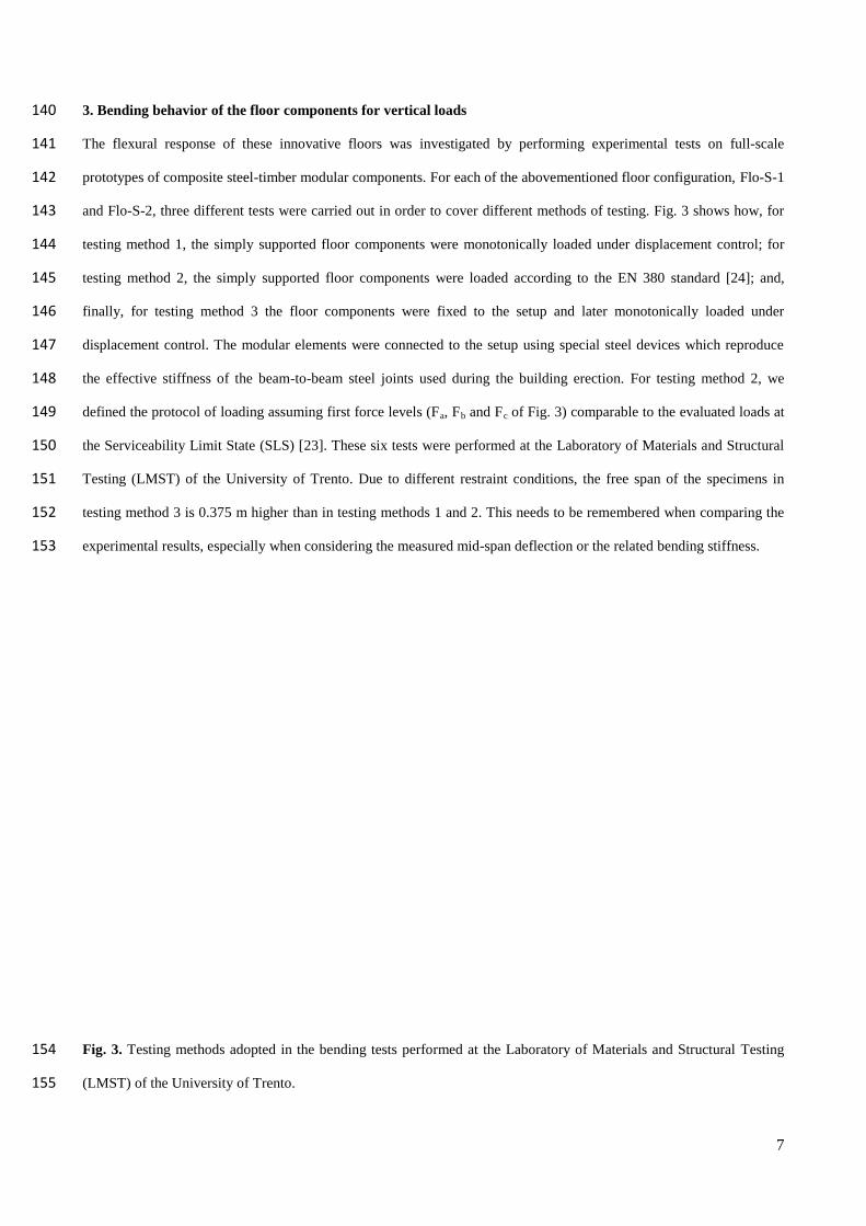
and Flo-S-2, three different tests were carried out in order to cover different methods of testing. Fig. 3 shows how, for 143
testing method 1, the simply supported floor components were monotonically loaded under displacement control; for 144
testing method 2, the simply supported floor components were loaded according to the EN 380 standard [24]; and, 145
finally, for testing method 3 the floor components were fixed to the setup and later monotonically loaded under 146
displacement control. The modular elements were connected to the setup using special steel devices which reproduce 147
the effective stiffness of the beam-to-beam steel joints used during the building erection. For testing method 2, we 148
defined the protocol of loading assuming first force levels (Fa, Fb and Fc of Fig. 3) comparable to the evaluated loads at 149
the Serviceability Limit State (SLS) [23]. These six tests were performed at the Laboratory of Materials and Structural 150
Testing (LMST) of the University of Trento. Due to different restraint conditions, the free span of the specimens in 151
testing method 3 is 0.375 m higher than in testing methods 1 and 2. This needs to be remembered when comparing the 152
experimental results, especially when considering the measured mid-span deflection or the related bending stiffness. 153
Fig. 3. Testing methods adopted in the bending tests performed at the Laboratory of Materials and Structural Testing 154
(LMST) of the University of Trento. 155
8
3.2 Method of loading and specimen instrumentation 156
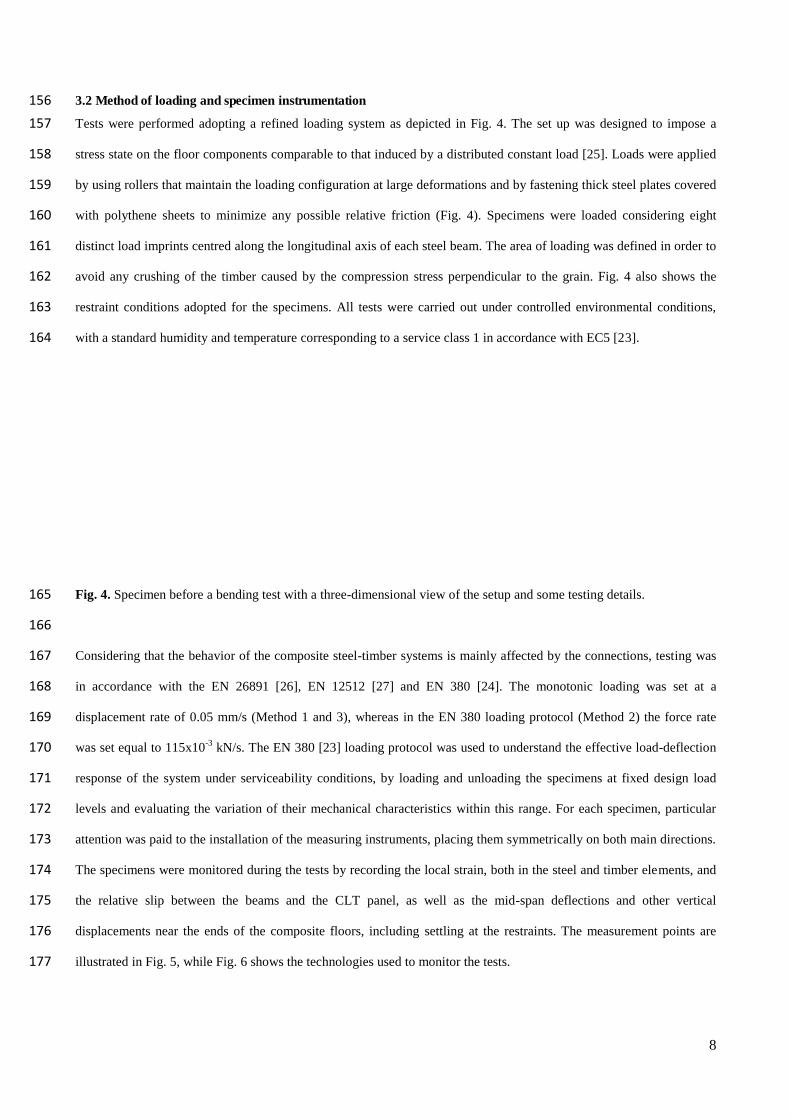
Tests were performed adopting a refined loading system as depicted in Fig. 4. The set up was designed to impose a 157
stress state on the floor components comparable to that induced by a distributed constant load [25]. Loads were applied 158
by using rollers that maintain the loading configuration at large deformations and by fastening thick steel plates covered 159
with polythene sheets to minimize any possible relative friction (Fig. 4). Specimens were loaded considering eight 160
distinct load imprints centred along the longitudinal axis of each steel beam. The area of loading was defined in order to 161
avoid any crushing of the timber caused by the compression stress perpendicular to the grain. Fig. 4 also shows the 162
restraint conditions adopted for the specimens. All tests were carried out under controlled environmental conditions, 163
with a standard humidity and temperature corresponding to a service class 1 in accordance with EC5 [23]. 164
Fig. 4. Specimen before a bending test with a three-dimensional view of the setup and some testing details. 165
166
Considering that the behavior of the composite steel-timber systems is mainly affected by the connections, testing was 167
in accordance with the EN 26891 [26], EN 12512 [27] and EN 380 [24]. The monotonic loading was set at a 168
displacement rate of 0.05 mm/s (Method 1 and 3), whereas in the EN 380 loading protocol (Method 2) the force rate 169
was set equal to 115x10-3 kN/s. The EN 380 [23] loading protocol was used to understand the effective load-deflection 170
response of the system under serviceability conditions, by loading and unloading the specimens at fixed design load 171
levels and evaluating the variation of their mechanical characteristics within this range. For each specimen, particular 172
attention was paid to the installation of the measuring instruments, placing them symmetrically on both main directions. 173
The specimens were monitored during the tests by recording the local strain, both in the steel and timber elements, and 174
the relative slip between the beams and the CLT panel, as well as the mid-span deflections and other vertical 175
displacements near the ends of the composite floors, including settling at the restraints. The measurement points are 176
illustrated in Fig. 5, while Fig. 6 shows the technologies used to monitor the tests. 177
9
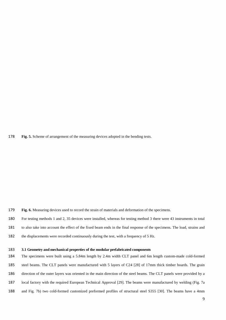
Fig. 5. Scheme of arrangement of the measuring devices adopted in the bending tests. 178
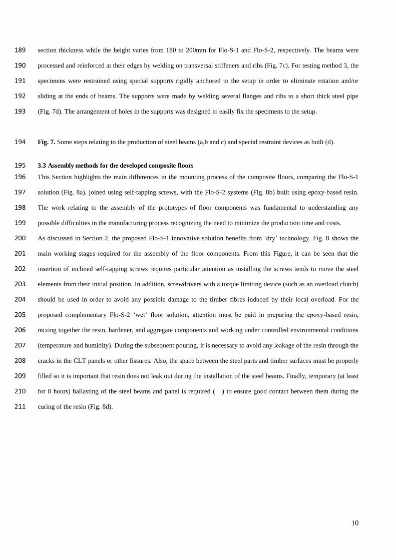
Fig. 6. Measuring devices used to record the strain of materials and deformation of the specimens. 179
For testing methods 1 and 2, 35 devices were installed, whereas for testing method 3 there were 43 instruments in total 180
to also take into account the effect of the fixed beam ends in the final response of the specimens. The load, strains and 181
the displacements were recorded continuously during the test, with a frequency of 5 Hz. 182
3.1 Geometry and mechanical properties of the modular prefabricated components 183
The specimens were built using a 5.84m length by 2.4m width CLT panel and 6m length custom-made cold-formed 184
steel beams. The CLT panels were manufactured with 5 layers of C24 [28] of 17mm thick timber boards. The grain 185
direction of the outer layers was oriented in the main direction of the steel beams. The CLT panels were provided by a 186
local factory with the required European Technical Approval [29]. The beams were manufactured by welding (Fig. 7a 187
and Fig. 7b) two cold-formed customized preformed profiles of structural steel S355 [30]. The beams have a 4mm 188
10
section thickness while the height varies from 180 to 200mm for Flo-S-1 and Flo-S-2, respectively. The beams were 189
processed and reinforced at their edges by welding on transversal stiffeners and ribs (Fig. 7c). For testing method 3, the 190
specimens were restrained using special supports rigidly anchored to the setup in order to eliminate rotation and/or 191
sliding at the ends of beams. The supports were made by welding several flanges and ribs to a short thick steel pipe 192
(Fig. 7d). The arrangement of holes in the supports was designed to easil y fix the specimens to the setup. 193
Fig. 7. Some steps relating to the production of steel beams (a,b and c) and special restraint devices as built (d). 194
3.3 Assembly methods for the developed composite floors 195
This Section highlights the main differences in the mounting process of the composite floors, comparing the Flo-S-1 196
solution (Fig. 8a), joined using self-tapping screws, with the Flo-S-2 systems (Fig. 8b) built using epoxy-based resin. 197
The work relating to the assembly of the prototypes of floor components was fundamental to understanding any 198
possible difficulties in the manufacturing process recognizing the need to minimize the production time and costs. 199
As discussed in Section 2, the proposed Flo-S-1 innovative solution benefits from ‘dry’ technology. Fig. 8 shows the 200
main working stages required for the assembly of the floor components. From this Figure, it can be seen that the 201
insertion of inclined self-tapping screws requires particular attention as installing the screws tends to move the steel 202
elements from their initial position. In addition, screwdrivers with a torque limiting device (such as an overload clutch) 203
should be used in order to avoid any possible damage to the timber fibres induced by their local overload. For the 204
proposed complementary Flo-S-2 ‘wet’ floor solution, attention must be paid in preparing the epoxy-based resin, 205
mixing together the resin, hardener, and aggregate components and working under controlled environmental conditions 206
(temperature and humidity). During the subsequent pouring, it is necessary to avoid any leakage of the resin through the 207
cracks in the CLT panels or other fissures. Also, the space between the steel parts and timber surfaces must be properly 208
filled so it is important that resin does not leak out during the installation of the steel beams. Finally, temporary (at least 209
for 8 hours) ballasting of the steel beams and panel is required ( ) to ensure good contact between them during the 210
curing of the resin (Fig. 8d). 211

11
Fig. 8. Main stages of assembly for the Flo-S-1 (a) and Flo-S-2 (b) floor specimens; (c) Flo-S-1 specimens as built 212
ballasted during the curing time of the epoxy-based resin; (d) Flo-S-2 specimens as built. 213
3.4 Preliminary tests to characterize the mechanical properties of the steel and timber elements 214
Within this experimental programme, several preliminary tests were conducted in order to evaluate the mechanical 215
behavior of the CLT panels and steel beams. Bending tests were conducted using a loading device and measuring 216
systems derived from those used for the composite floor components. Fig. 9 shows the charts of the load-deflection 217
curves measured. A set of three specimens for each element: CLT panels, type 1 steel beams (Flo-S-1) and type 2 steel 218
beams (Flo-S-2) was considered a statistically representative sample for this experimental study. From the charts of Fig. 219
9, it can be seen that the load-deflection curves of the steel beams are superimposed, whereas the response of the CLT 220
panels is slightly variable. Assuming an elastic behavior of the elements, based on the Euler–Bernoulli beam theory 221
[31], we estimated the Young’s modulus (E) of the steel beams and the maximum normal stresses. 222
12
Fig. 9. Preliminary tests performed on the floor components: steel beams and timber panels. 223
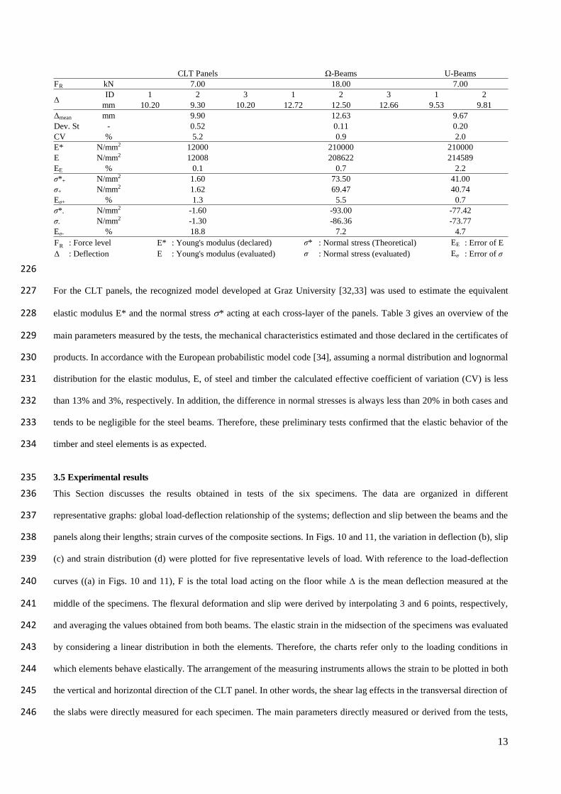
Table 3 224
Comparison between the nominal and effective mechanical characteristics of the timber and steel elements 225
13
226
For the CLT panels, the recognized model developed at Graz University [32,33] was used to estimate the equivalent 227
elastic modulus E* and the normal stress * acting at each cross-layer of the panels. Table 3 gives an overview of the 228
main parameters measured by the tests, the mechanical characteristics estimated and those declared in the certificates of 229
products. In accordance with the European probabilistic model code [34], assuming a normal distribution and lognormal 230
distribution for the elastic modulus, E, of steel and timber the calculated effective coefficient of variation (CV) is less 231
than 13% and 3%, respectively. In addition, the difference in normal stresses is always less than 20% in both cases and 232
tends to be negligible for the steel beams. Therefore, these preliminary tests confirmed that the elastic behavior of the 233
timber and steel elements is as expected. 234
3.5 Experimental results 235
This Section discusses the results obtained in tests of the six specimens. The data are organized in different 236
representative graphs: global load-deflection relationship of the systems; deflection and slip between the beams and the 237
panels along their lengths; strain curves of the composite sections. In Figs. 10 and 11, the variation in deflection (b), slip 238
(c) and strain distribution (d) were plotted for five representative levels of load. With reference to the load-deflection 239
curves ((a) in Figs. 10 and 11), F is the total load acting on the floor while is the mean deflection measured at the 240
middle of the specimens. The flexural deformation and slip were derived by interpolating 3 and 6 points, respectively, 241
and averaging the values obtained from both beams. The elastic strain in the midsection of the specimens was evaluated 242
by considering a linear distribution in both the elements. Therefore, the charts refer only to the loading conditions in 243
which elements behave elastically. The arrangement of the measuring instruments allows the strain to be plotted in both 244
the vertical and horizontal direction of the CLT panel. In other words, the shear lag effects in the transversal direction of 245
the slabs were directly measured for each specimen. The main parameters directly measured or derived from the tests, 246
FR : Force level E* : Young'smodulus (declared) j* : Normalstress (Theoretical) EE : Error of E〉 : Deflection E : Young'smodulus (evaluated) j : Normalstress (evaluated) Ej : Error of j
CLT Panels っ-Beams U-BeamsFR kN 7.00 18.00 7.00
〉 ID 1 2 3 1 2 3 1 2mm 10.20 9.30 10.20 12.72 12.50 12.66 9.53 9.81
〉mean mm 9.90 12.63 9.67Dev. St - 0.52 0.11 0.20CV % 5.2 0.9 2.0E* N/mm2 12000 210000 210000E N/mm2 12008 208622 214589EE % 0.1 0.7 2.2j*+ N/mm2 1.60 73.50 41.00j+ N/mm2 1.62 69.47 40.74Ej+ % 1.3 5.5 0.7j* - N/mm2 -1.60 -93.00 -77.42j- N/mm2 -1.30 -86.36 -73.77Ej- % 18.8 7.2 4.7
14
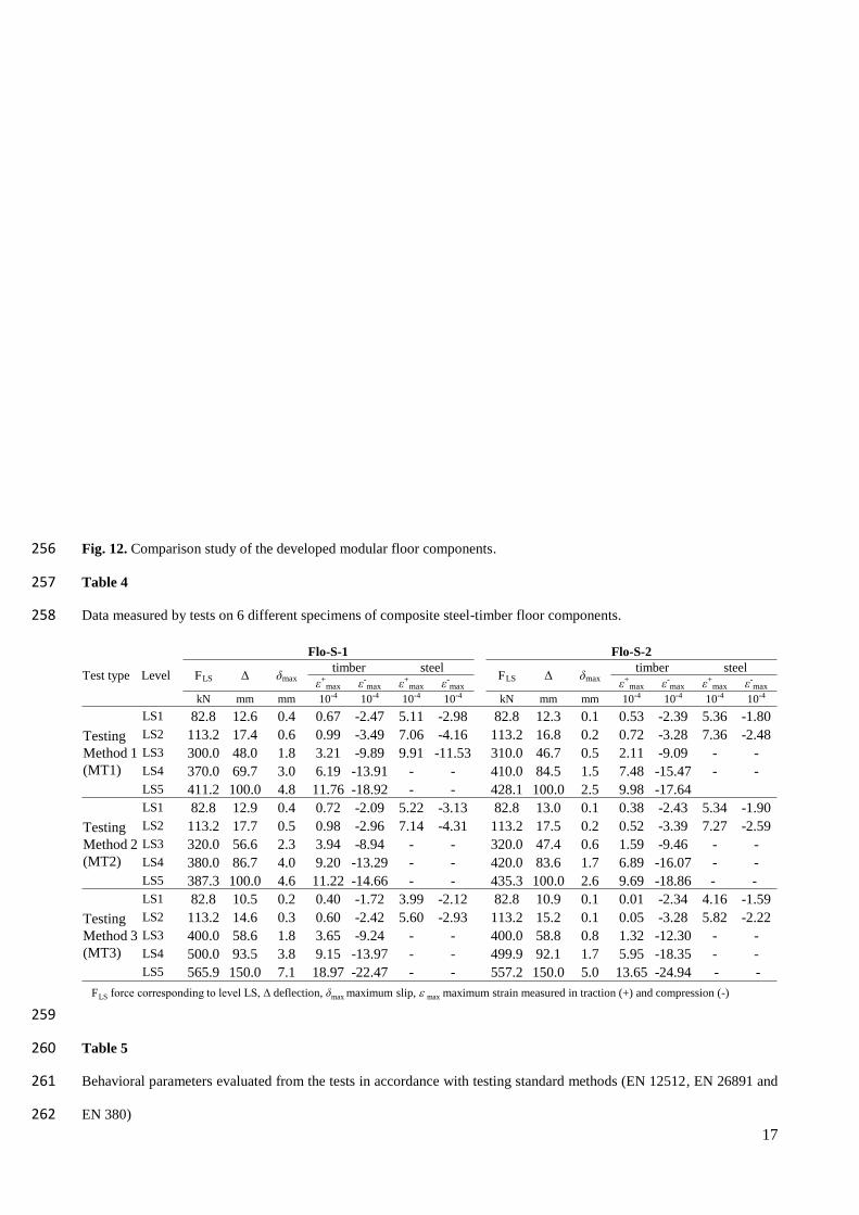
in accordance with the testing standards recommendations, are also listed in Table 4. A comparison study on the load-247
deflection curves and elastic bending stiffnesses is given in Fig. 12 and Table 5. The charts in Fig. 12 also show the 248
yield points of the systems estimated in accordance with the EN 12512 [27]. The corresponding yield load, yield 249
deflection, initial stiffness and the stiffness in the second branch of the load-deflection curves are illustrated in Table 5. 250
Figs. 10 and 11, together with Table 4, demonstrate that the developed composite steel-timber systems have an 251
extraordinaril y ductile behavior, with a load carrying capacity (FC) about three times higher than the relative design 252
loads (Fd,ULS) in the less favorable case. 253

15
Fig. 10. Experimental behavior of Flo-S-1 floor components under different testing methods. 254
16
Fig. 11. Experimental behavior of Flo-S-2 floor components under different testing methods. 255
17
Fig. 12. Comparison study of the developed modular floor components. 256
Table 4 257
Data measured by tests on 6 different specimens of composite steel-timber floor components. 258
259
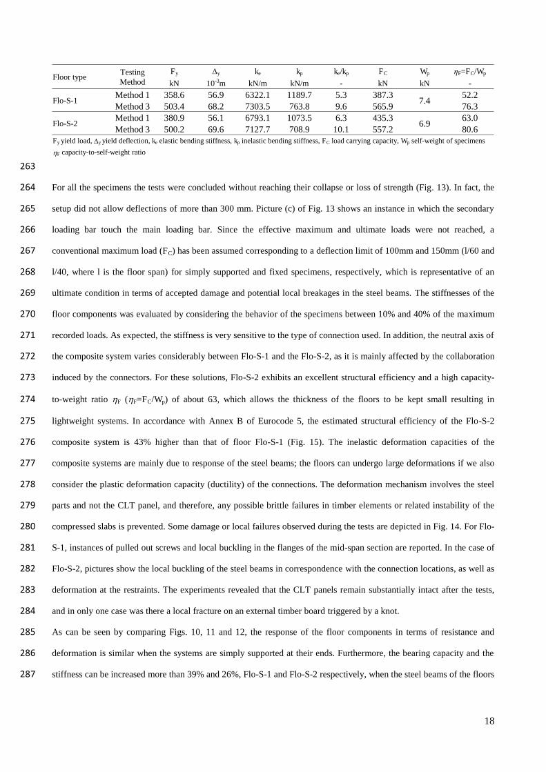
Table 5 260
Behavioral parameters evaluated from the tests in accordance with testing standard methods (EN 12512, EN 26891 and 261
EN 380) 262
Flo-S-1 Flo-S-2
Test type Level FLS 〉 hmaxtimber steel
FLS 〉 hmaxtimber steel
i+max i-max i+max i-max i+max i-max i+max i-max
kN mm mm 10-4 10-4 10-4 10-4 kN mm mm 10-4 10-4 10-4 10-4
Testing Method 1 (MT1)
LS1 82.8 12.6 0.4 0.67 -2.47 5.11 -2.98 82.8 12.3 0.1 0.53 -2.39 5.36 -1.80LS2 113.2 17.4 0.6 0.99 -3.49 7.06 -4.16 113.2 16.8 0.2 0.72 -3.28 7.36 -2.48LS3 300.0 48.0 1.8 3.21 -9.89 9.91 -11.53 310.0 46.7 0.5 2.11 -9.09 - -LS4 370.0 69.7 3.0 6.19 -13.91 - - 410.0 84.5 1.5 7.48 -15.47 - -LS5 411.2 100.0 4.8 11.76 -18.92 - - 428.1 100.0 2.5 9.98 -17.64
Testing Method 2 (MT2)
LS1 82.8 12.9 0.4 0.72 -2.09 5.22 -3.13 82.8 13.0 0.1 0.38 -2.43 5.34 -1.90LS2 113.2 17.7 0.5 0.98 -2.96 7.14 -4.31 113.2 17.5 0.2 0.52 -3.39 7.27 -2.59LS3 320.0 56.6 2.3 3.94 -8.94 - - 320.0 47.4 0.6 1.59 -9.46 - -LS4 380.0 86.7 4.0 9.20 -13.29 - - 420.0 83.6 1.7 6.89 -16.07 - -LS5 387.3 100.0 4.6 11.22 -14.66 - - 435.3 100.0 2.6 9.69 -18.86 - -
TestingMethod 3 (MT3)
LS1 82.8 10.5 0.2 0.40 -1.72 3.99 -2.12 82.8 10.9 0.1 0.01 -2.34 4.16 -1.59LS2 113.2 14.6 0.3 0.60 -2.42 5.60 -2.93 113.2 15.2 0.1 0.05 -3.28 5.82 -2.22LS3 400.0 58.6 1.8 3.65 -9.24 - - 400.0 58.8 0.8 1.32 -12.30 - -LS4 500.0 93.5 3.8 9.15 -13.97 - - 499.9 92.1 1.7 5.95 -18.35 - -LS5 565.9 150.0 7.1 18.97 -22.47 - - 557.2 150.0 5.0 13.65 -24.94 - -
FLS force corresponding to level LS, 〉 deflection, hmaxmaximum slip, e max maximum strain measured in traction (+) and compression (-)
18
263
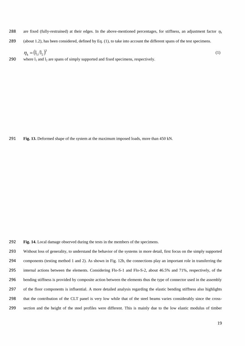
For all the specimens the tests were concluded without reaching their collapse or loss of strength (Fig. 13). In fact, the 264
setup did not allow deflections of more than 300 mm. Picture (c) of Fig. 13 shows an instance in which the secondary 265
loading bar touch the main loading bar. Since the effective maximum and ultimate loads were not reached, a 266
conventional maximum load (FC) has been assumed corresponding to a deflection limit of 100mm and 150mm (l/60 and 267
l/40, where l is the floor span) for simply supported and fixed specimens, respectively, which is representative of an 268
ultimate condition in terms of accepted damage and potential local breakages in the steel beams. The stiffnesses of the 269
floor components was evaluated by considering the behavior of the specimens between 10% and 40% of the maximum 270
recorded loads. As expected, the stiffness is very sensitive to the type of connection used. In addition, the neutral axis of 271
the composite system varies considerably between Flo-S-1 and the Flo-S-2, as it is mainly affected by the collaboration 272
induced by the connectors. For these solutions, Flo-S-2 exhibits an excellent structural efficiency and a high capacity-273
to-weight ratio F (F=FC/Wp) of about 63, which allows the thickness of the floors to be kept small resulting in 274
lightweight systems. In accordance with Annex B of Eurocode 5, the estimated structural efficiency of the Flo-S-2 275
composite system is 43% higher than that of floor Flo-S-1 (Fig. 15). The inelastic deformation capacities of the 276
composite systems are mainly due to response of the steel beams; the floors can undergo large deformations if we also 277
consider the plastic deformation capacity (ductility) of the connections. The deformation mechanism involves the steel 278
parts and not the CLT panel, and therefore, any possible brittle failures in timber elements or related instability of the 279
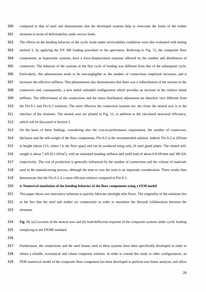
compressed slabs is prevented. Some damage or local failures observed during the tests are depicted in Fig. 14. For Flo-280
S-1, instances of pulled out screws and local buckling in the flanges of the mid-span section are reported. In the case of 281
Flo-S-2, pictures show the local buckling of the steel beams in correspondence with the connection locations, as well as 282
deformation at the restraints. The experiments revealed that the CLT panels remain substantially intact after the tests, 283
and in only one case was there a local fracture on an external timber board triggered by a knot. 284
As can be seen by comparing Figs. 10, 11 and 12, the response of the floor components in terms of resistance and 285
deformation is similar when the systems are simply supported at their ends. Furthermore, the bearing capacity and the 286
stiffness can be increased more than 39% and 26%, Flo-S-1 and Flo-S-2 respectively, when the steel beams of the floors 287
Floor typeTestingMethod
Fy 〉y ke kp ke/kp FC Wp さF=FC/Wp
kN 10-3m kN/m kN/m - kN kN -
Flo-S-1Method 1 358.6 56.9 6322.1 1189.7 5.3 387.3
7.452.2
Method 3 503.4 68.2 7303.5 763.8 9.6 565.9 76.3
Flo-S-2Method 1 380.9 56.1 6793.1 1073.5 6.3 435.3
6.963.0
Method 3 500.2 69.6 7127.7 708.9 10.1 557.2 80.6Fy yield load, y yield deflection, ke elastic bending stiffness, kp inelastic bending stiffness, FC load carrying capacity, Wp self-weight of specimens
F capacity-to-self-weight ratio
19
are fixed (fully-restrained) at their edges. In the above-mentioned percentages, for stiffness, an adjustment factor k 288
(about 1.2), has been considered, defined by Eq. (1), to take into account the different spans of the test specimens. 289
321 llk (1)
where l1 and l2 are spans of simply supported and fixed specimens, respectively. 290
Fig. 13. Deformed shape of the system at the maximum imposed loads, more than 450 kN. 291
Fig. 14. Local damage observed during the tests in the members of the specimens. 292
Without loss of generality, to understand the behavior of the systems in more detail, first focus on the simply supported 293
components (testing method 1 and 2). As shown in Fig. 12b, the connections play an important role in transferring the 294
internal actions between the elements. Considering Flo-S-1 and Flo-S-2, about 46.5% and 71%, respectively, of the 295
bending stiffness is provided by composite action between the elements thus the type of connector used in the assembly 296
of the floor components is influential. A more detailed analysis regarding the elastic bending stiffness also highlights 297
that the contribution of the CLT panel is very low while that of the steel beams varies considerably since the cross-298
section and the height of the steel profiles were different. This is mainly due to the low elastic modulus of timber 299
20
compared to that of steel and demonstrates that the developed systems help to overcome the limits of the timber 300
elements in terms of deformability under service loads. 301
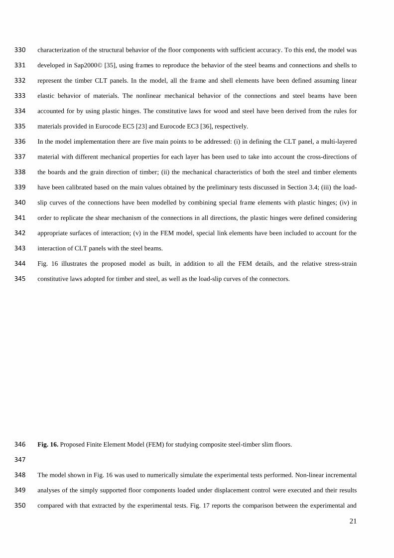
The effects on the bending behavior of the cyclic loads under serviceability conditions were also evaluated with testing 302
method 2, by applying the EN 380 loading procedure to the specimens. Referring to Fig. 15, the composite floor 303
components, as hyperstatic systems, have a force-displacement response affected by the number and distribution of 304
connectors. The behavior of the systems in the first cycle of loading was different from that of the subsequent cycle. 305
Particularly, this phenomenon tends to be non-negligible as the number of connections employed increases, and it 306
increases the effective stiffness. This phenomenon also demonstrates that there was a redistribution of the stresses in the 307
connectors and, consequently, a new initial unloaded configuration which provides an increase in the relative initial 308
stiffness. The effectiveness of the connections and the stress distribution adjustment are therefore very different from 309
the Flo-S-1 and Flo-S-2 solutions. The more effective the connection systems are, the closer the neutral axis is to the 310
interface of the elements. The neutral axes are plotted in Fig. 15, in addition to the calculated structural efficiency, 311
which will be discussed in Section 5. 312
On the basis of these findings, considering also the cost-to-performance requirement, the number of connectors, 313
thickness and the self-weight of the floor components, Flo-S-2 is the recommended solution. Indeed, Flo-S-2 is 265mm 314
in height (about l/23, where l is the floor span) and can be produced using only 24 steel glued plates. The related self-315
weight is about 7 kN (0.5 kN/m2), with an estimated bending stiffness and yield load of about 6.8 kN/mm and 380 kN, 316
respectively. The cost of production is generally influenced by the number of connections and the volume of materials 317
used in the manufacturing process, although the time to cure the resin is an important consideration. These results thus 318
demonstrate that the Flo-S-2 is a more efficient solution compared to Flo-S-1. 319
4. Numerical simulation of the bending behavior of the floor components using a FEM model 320
This paper shows two innovative solutions to quickly fabricate ultralight slim floors. The originality of the solutions lies 321
in the fact that the steel and timber act compositely in order to maximize the flexural collaboration between the 322
elements. 323
Fig. 15. (a) Location of the neutral axes and (b) load-deflection response of the composite systems under cyclic loading 324
complying to the EN380 standard. 325
326
Furthermore, the connections and the steel beams used in these systems have been specifically developed in order to 327
obtain a reliable, economical and robust composite solution. In order to extend this study to other configurations, an 328
FEM numerical model of the composite floor component has been developed to perform non-linear analyses, and allow 329
21
characterization of the structural behavior of the floor components with sufficient accuracy. To this end, the model was 330
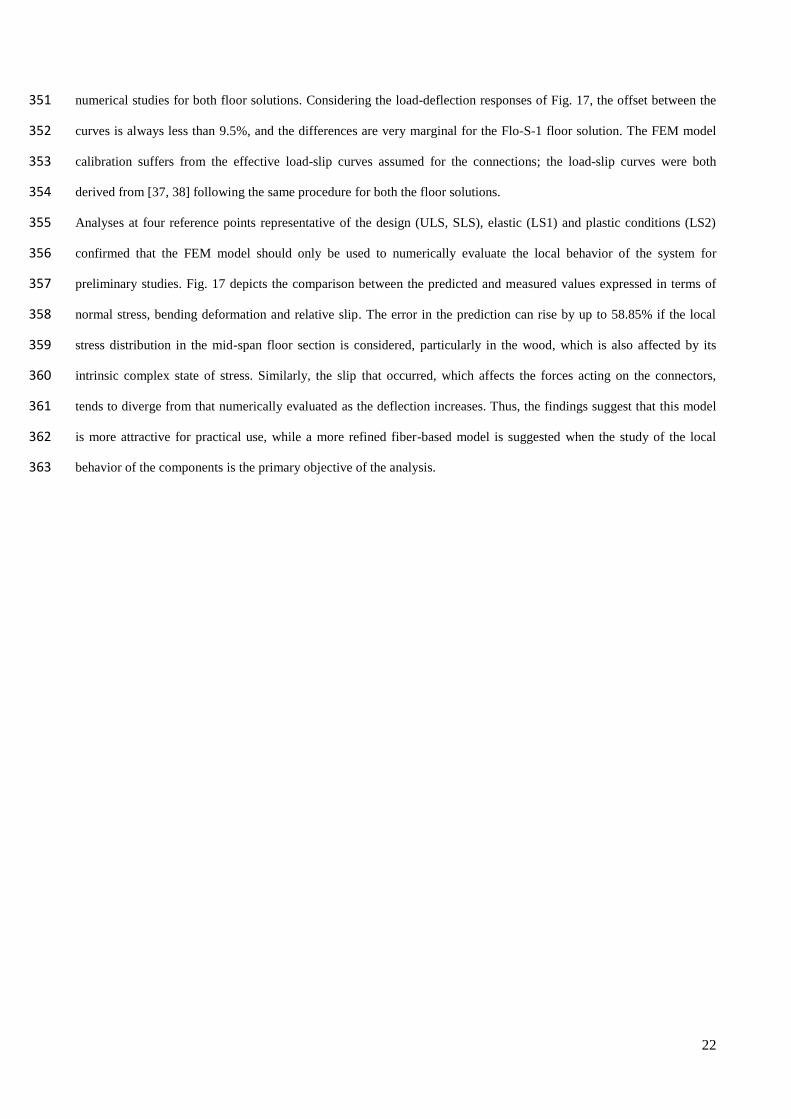
developed in Sap2000© [35], using frames to reproduce the behavior of the steel beams and connections and shells to 331
represent the timber CLT panels. In the model, all the frame and shell elements have been defined assuming linear 332
elastic behavior of materials. The nonlinear mechanical behavior of the connections and steel beams have been 333
accounted for by using plastic hinges. The constitutive laws for wood and steel have been derived from the rules for 334
materials provided in Eurocode EC5 [23] and Eurocode EC3 [36], respectively. 335
In the model implementation there are five main points to be addressed: (i) in defining the CLT panel, a multi-layered 336
material with different mechanical properties for each layer has been used to take into account the cross-directions of 337
the boards and the grain direction of timber; (ii) the mechanical characteristics of both the steel and timber elements 338
have been calibrated based on the main values obtained by the preliminary tests discussed in Section 3.4; (iii) the load-339
slip curves of the connections have been modelled by combining special frame elements with plastic hinges; (iv) in 340
order to replicate the shear mechanism of the connections in all directions, the plastic hinges were defined considering 341
appropriate surfaces of interaction; (v) in the FEM model, special link elements have been included to account for the 342
interaction of CLT panels with the steel beams. 343
Fig. 16 illustrates the proposed model as built, in addition to all the FEM details, and the relative stress-strain 344
constitutive laws adopted for timber and steel, as well as the load-slip curves of the connectors. 345
Fig. 16. Proposed Finite Element Model (FEM) for studying composite steel-timber slim floors. 346
347
The model shown in Fig. 16 was used to numerically simulate the experimental tests performed. Non-linear incremental 348
analyses of the simply supported floor components loaded under displacement control were executed and their results 349
compared with that extracted by the experimental tests. Fig. 17 reports the comparison between the experimental and 350
22
numerical studies for both floor solutions. Considering the load-deflection responses of Fig. 17, the offset between the 351
curves is always less than 9.5%, and the differences are very marginal for the Flo-S-1 floor solution. The FEM model 352
calibration suffers from the effective load-slip curves assumed for the connections; the load-slip curves were both 353
derived from [37, 38] following the same procedure for both the floor solutions. 354
Analyses at four reference points representative of the design (ULS, SLS), elastic (LS1) and plastic conditions (LS2) 355
confirmed that the FEM model should only be used to numerically evaluate the local behavior of the system for 356
preliminary studies. Fig. 17 depicts the comparison between the predicted and measured values expressed in terms of 357
normal stress, bending deformation and relative slip. The error in the prediction can rise by up to 58.85% if the local 358
stress distribution in the mid-span floor section is considered, particularly in the wood, which is also affected by its 359
intrinsic complex state of stress. Similarly, the slip that occurred, which affects the forces acting on the connectors, 360
tends to diverge from that numerically evaluated as the deflection increases. Thus, the findings suggest that this model 361
is more attractive for practical use, while a more refined fiber-based model is suggested when the study of the local 362
behavior of the components is the primary objective of the analysis. 363
23
Fig. 17. Comparison between the experimental and numerical studies of the non-linear behavior of the Flo-S-1 and Flo-364
S-2 floor components. 365
5. Model for the design of the composite floor components 366
The laboratory tests have revealed that the behavior of the composite floor components, as very slim systems, is mainly 367
guided by the deflection limitations and not the bearing capacity (FC), which is several times higher than the ultimate 368
design loads (Fd,ULS). From Fig. 12, it follows also that design loads calculated in accordance with the Italian Building 369
Code [39] are lower than the first yield loads. In other words, the measured load-deflection behaviors are markedly 370
linear-elastic. The design problem of composite systems with semi-rigid connections, such as those presented here, was 371
first studied in the 1956 by Möhler [40], and afterwards researchers concentrated on applying this model to other case 372
studies [41,42]. In the Möhler approach the underlying assumptions are: (1) for both elements the simple bending theory 373
can be used, (2) the shear deformation is disregarded in solving the equilibrium and deformation differential equations, 374
(3) the connection of elements is assumed as continuous, (4) the cross-sections and stiffness of connections are constant 375
24
along the main direction of the composite system and (5) the load-slip behavior of connection is assumed linear elastic. 376
Accepting some minimal errors, tolerable for engineering purposes, in the case of simply supported composite system it 377
is possible to define an equivalent bending stiffness to be used in the final solution of the differential equation. 378
Moreover, for simple load cases, i.e. uniformly distributed load, the differential equation can be reduced in a closed 379
form and the model extended to more complex cross-section beams as reported in Appendix B of EC5 [23]. 380
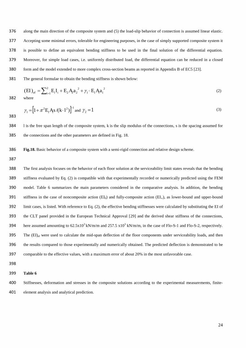
The general formulae to obtain the bending stiffness is shown below: 381
2
1
21111
2222)(
i iief aAEaAEIEEI (2)
where 382
1211
21 )/(1
lksAE and 12 (3)
383
l is the free span length of the composite system, k is the slip modulus of the connections, s is the spacing assumed for 384
the connections and the other parameters are defined in Fig. 18. 385
Fig.18. Basic behavior of a composite system with a semi-rigid connection and relative design scheme. 386
387
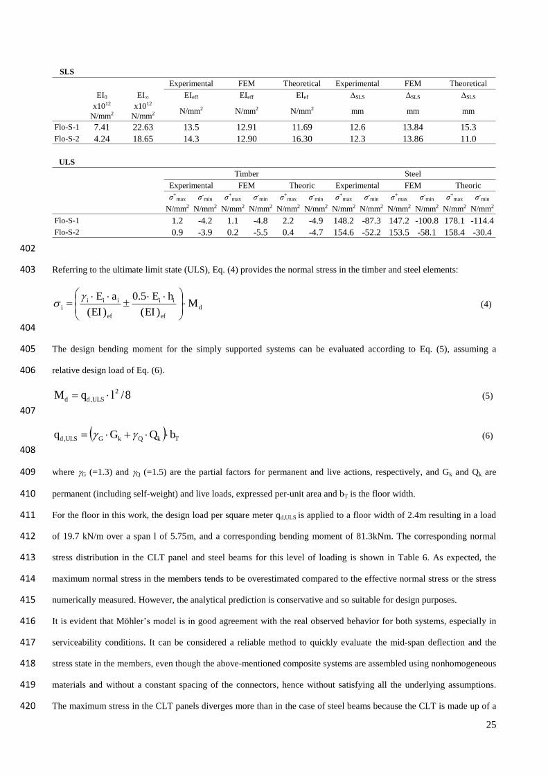
The first analysis focuses on the behavior of each floor solution at the serviceability limit states reveals that the bending 388
stiffness evaluated by Eq. (2) is compatible with that experimentally recorded or numerically predicted using the FEM 389
model. Table 6 summarizes the main parameters considered in the comparative analysis. In addition, the bending 390
stiffness in the case of noncomposite action (EI0) and fully-composite action (EI∞), as lower-bound and upper-bound 391
limit cases, is listed. With reference to Eq. (2), the effective bending stiffnesses were calculated by substituting the EI of 392
the CLT panel provided in the European Technical Approval [29] and the derived shear stiffness of the connections, 393
here assumed amounting to 62.5x10³ kN/m/m and 257.5 x10³ kN/m/m, in the case of Flo-S-1 and Flo-S-2, respectively. 394
The (EI)ef were used to calculate the mid-span deflection of the floor components under serviceability loads, and then 395
the results compared to those experimentally and numerically obtained. The predicted deflection is demonstrated to be 396
comparable to the effective values, with a maximum error of about 20% in the most unfavorable case. 397
398
Table 6 399
Stiffnesses, deformation and stresses in the composite solutions according to the experimental measurements, finite-400
element analysis and analytical prediction. 401
25
402
Referring to the ultimate limit state (ULS), Eq. (4) provides the normal stress in the timber and steel elements: 403
def
ii
ef
iiii M
EI
hE
EI
aE
)(
5.0
)(
(4)
404
The design bending moment for the simply supported systems can be evaluated according to Eq. (5), assuming a 405
relative design load of Eq. (6). 406
8/2, lqM ULSdd (5)
407
TkQkGULSd bQGq , (6)
408
where G (=1.3) and Q (=1.5) are the partial factors for permanent and live actions, respectively, and Gk and Qk are 409
permanent (including self-weight) and live loads, expressed per-unit area and bT is the floor width. 410
For the floor in this work, the design load per square meter qd,ULS is applied to a floor width of 2.4m resulting in a load 411
of 19.7 kN/m over a span l of 5.75m, and a corresponding bending moment of 81.3kNm. The corresponding normal 412
stress distribution in the CLT panel and steel beams for this level of loading is shown in Table 6. As expected, the 413
maximum normal stress in the members tends to be overestimated compared to the effective normal stress or the stress 414
numerically measured. However, the analytical prediction is conservative and so suitable for design purposes. 415
It is evident that Möhler’s model is in good agreement with the real observed behavior for both systems, especially in 416
serviceability conditions. It can be considered a reliable method to quickly evaluate the mid-span deflection and the 417
stress state in the members, even though the above-mentioned composite systems are assembled using nonhomogeneous 418
materials and without a constant spacing of the connectors, hence without satisfying all the underlying assumptions. 419
The maximum stress in the CLT panels diverges more than in the case of steel beams because the CLT is made up of a 420
SLSExperimental FEM Theoretical Experimental FEM Theoretical
EI0 EI∞ EIeff EIeff EIef 〉SLS 〉SLS 〉SLS
x1012
N/mm2x1012
N/mm2 N/mm2 N/mm2 N/mm2 mm mm mm
Flo-S-1 7.41 22.63 13.5 12.91 11.69 12.6 13.84 15.3Flo-S-2 4.24 18.65 14.3 12.90 16.30 12.3 13.86 11.0
ULSTimber Steel
Experimental FEM Theoric Experimental FEM Theoric
j+max j-
min j+max j-
min j+max j-
min j+max j-
min j+max j-
min j+max j-
min
N/mm2 N/mm2 N/mm2 N/mm2 N/mm2 N/mm2 N/mm2 N/mm2 N/mm2 N/mm2 N/mm2 N/mm2
Flo-S-1 1.2 -4.2 1.1 -4.8 2.2 -4.9 148.2 -87.3 147.2 -100.8 178.1 -114.4Flo-S-2 0.9 -3.9 0.2 -5.5 0.4 -4.7 154.6 -52.2 153.5 -58.1 158.4 -30.4
26
large variety of materials and types of boards, which increases the uncertainty of the mechanical properties of the wood. 421
Furthermore, the strain in the CLT panel is affected by the intrinsic uncertainty of the wood, and thus a numerical 422
model cannot take into account its anisotropic behavior without increasing the complexity of the problem solution. 423
Möhler’s model has proved to be an effective way to simply design these developed composite systems since their 424
slenderness makes them susceptible to the serviceability requirements expressed in terms of deflection limits. The steel 425
beams, CLT panels and connections behave elastically for code-defined [39] ultimate loads, here demonstrated to be 426
very low compared to the real bearing capacities of the systems. 427
6. Conclusion 428
Construction systems with modular and prefabricated elements represent viable alternative solutions for the rapid 429
erection of multi-storey residential buildings. The challenge for a more sustainable built environment has recently 430
moved the community to devising building construction technologies that pay particular attention to energy-efficiency. 431
Buildings have to drastically reduce the energy consumed during their whole life cycle, and the related emission of 432
carbon dioxide (CO2) into the atmosphere. This paper has clearly shown that the combination of new construction 433
products with new construction and erection techniques can help to support the objectives of sustainability and is a very 434
promising way to build green residential buildings in a fast and easy way. The research has focused on the realisation of 435
innovative engineered floors based on prefabricated steel-timber composite components. The floor cross-section has 436
been optimized to maximize its structural efficiency and to reduce the use of materials. Floor components are made 437
offsite by joining CLT panels with cold-formed custom-shaped steel beams. Two particular technologies have been 438
described that offer benefits in terms of lightness, sustainability, ease of construction and, when no longer required, ease 439
of deconstruction and reuse. 440
The behavior of the developed floor components has been investigated through experimental tests, studying both the 441
elastic and inelastic force-deformation responses, in addition to their local mechanisms and damage. The findings 442
demonstrate that with this new technology it is very simple to design ductile floors with an exceptional load-carrying 443
capacity, while at the same time limiting their cross-section height. The results suggest that the design of such floors is 444
mainly guided by the serviceability requirements and the behavior remains elastic even at high loading levels. Tests 445
have also helped in the implementation of a numerical FEM model for studying other steel-timber composite solutions. 446
A manual calculation procedure has been presented for design purposes. This analysis includes common rules provided 447
by the current standards for timber and steel structures. 448
The findings of this research allow the following general conclusions to be drawn: 449
The developed systems are innovative not just in the combination of CLT panels with cold-formed beams, but 450
also in the particular profiles of the steel beams which are equipped with special mechanical parts used in the 451
27
assembly of the elements. These solutions are derived from a more general composite technology currently 452
protected by patent rights. 453
From the point of view of construction, the solutions presented here have several advantages in the way they 454
are mounted on-site, allowing floors to be built in a faster and easier way than traditional concrete-based 455
composite solutions. Modular elements are fastened using only bolts and screws. 456
Both of the tested systems showed an exceptional bearing capacity compared to the design loads, with a 457
considerable structural efficiency (close to 0.7 for Flo-S-2) and effective yield loads almost three times higher 458
(Fy=381kN compared to qy=27.6 kN/m2). 459
The structural performance is very significant considering the amount of wood and steel used. Averaging Flo-460
S-1 and Flo-S-2, a square meter of 6m span floor takes about 35kg of wood, 7kg of steel and 0.4kg of epoxy-461
based resin, and thus uses about 82% natural material, 17% recyclable material and only 1% non-recyclable 462
material. This composite steel-timber technology is therefore an effective solution to supporting the objectives 463
of sustainability in construction. 464
The floor systems force the inelastic deformation into the steel beams, although, at high loading levels, (four or 465
five times higher than the design loads) connections can undergo plastic behavior. Any damage occurs in the 466
steel beams, while the CLT panel remains elastic. The floor systems remain in equilibrium since the instability 467
of the timber and steel elements is prevented by the connections, which provide a very high slip ductility 468
capacity even for a large flexural deformation. 469
The adoption of fixed restraints at the ends of the steel beams can considerably increase the stiffness (up to 470
about 40%) and strength (up to about 37%) of the floors. The beam joint details for both floor solutions can be 471
adapted to suit the design needs without affecting their manufacturing process. 472
Two models are provided for studying the bending behavior of the floor components. The FEM model is 473
recommended to perform numerical simulations to establish the most likely behavior of composite steel-timber 474
floors. A manual calculation analysis based on the recognized け-method derived from Möhler and included in 475
the current Eurocode standard is then given to design the presented floor solutions. 476
In future research, the diaphragm behavior of floors made with these modular prefabricated elements will be 477
investigated. An experimental study of a full-scale prototype of floor system has been presented in [43]. Further studies 478
relating to the issues of long-term behavior of the floors under constant loads, their fire resistance and vibrational 479
performance remain to be addressed. On the basis of the promising findings presented in this paper, work on the 480
remaining issues is continuing and appears fully justified. 481
482
28
483
Acknowledgements 484
This research was supported by the Regional Development Public Fund of the Autonomous Province of Trento (Italy) 485
and by the Italian company ‘Pre metal Spa’. The authors appreciate the assistance and support of Andrea Poli and 486
Thomas Dusatti regarding the implementation of experiments for the research, and the Laboratory team, in particular, 487
the technicians Alfredo Pojer and Tiziano Dalla Torre for their help during the tests. Fruitful discussions in the early 488
stages of experiments with Professor Maurizio Piazza are gratefully acknowledged. The authors’ thanks are also 489
extended to the research collaborator Luigi Farinati and former student Matteo Pangrazzi for their valuable contribution 490
to this work. 491
References 492
[1] Newcombe MP, Pampanin S, Buchanan AH, Palermo A. Section analysis and cyclic behavior of post-tensioned 493
jointed ductile connections for multi-story timber building. Journal of Earthquake Engineering 2008; 12 (S1): 83–110. 494
DOI:10.1080/13632460801925632. 495
[2] Wanninger F, Frangi A. Experimental and analytical analysis of a post-tensioned timber connection under gravity 496
loads. Engineering Structures 2014; 70: 117–129. DOI:10.1016/j.engstruct.2014.03.042. 497
[3] Polastri A, Pozza L, Loss C, Smith I. Numerical analyses of high- and medium-rise CLT buildings braced with cores 498
and additional shear wall. In: Proceedings of the 3rd International Conference on Structures and Architecture, 499
Guimarães, Portugal; 27th-29th July 2016. 500
[4] Ceccotti A. Composite concrete-timber structures. Progress in Structural Engineering and Materials 2002; 4:264–501
275. DOI: 10.1002/pse.126. 502
[5] Gutkowski R, Brown K, Shigidi A, Natterer J. Laboratory tests of composite wood–concrete beams. Construction 503
and Building Materials 2008; 22(6): 1059–1066. DOI:10.1016/j.conbuildmat.2007.03.013. 504
[6] Fernández Cabo JL, Fernández-Lavandera J, Avila-Jalvo JM. Wood-Concrete and Wood-Wood Mixed Beams: 505
Rational Basis for Selecting Connections. Journal of Structural Engineering 2008; 134 (3): 440-447. 506
DOI:10.1061/(ASCE)0733-9445(2008)134:3(440) 507
[7] Skinner J, Bregulla J, Harris R, Paine K, Walker P. Screw connectors for thin topping, timber-concrete composites. 508
Materials and Structures 2004; 47 (11): 1891-1899. DOI 10.1617/s11527-013-0158-6. 509
[8] Brunner M, Romer M, Schnüriger M. Timber-concrete-composite with an adhesive connector (wet on wet process). 510
Materials and Structures 2007; 40(1): 119-126. DOI 10.1617/s11527-006-9154-4. 511
[9] Yeoh D, Fragiacomo M, De Franceschi M, Heng Boon K. State of the art on timber-concrete composite structures: 512
Literature review 2011; 137(10):1085-1095. DOI: 10.1061/(ASCE)ST.1943-541X.0000353, 1085-1095. 513
[10] Turrini G, Piazza M. Una tecnica di recupero statico dei solai in legno. Recuperare 1983a; 5:224-237. (in Italian). 514
[11] Turrini G, Piazza M. Il comportamento statico della struttura mista legno-calcestruzzo. Recuperare 1983b; 6:214-515
225 (in Italian). 516
[12] Giongo I, Piazza M, Tomasi R. Out of plane refurbishment techniques of existing timber floors by means of timber 517
to timber composite structures. In: Proceedings of World Conference on Timber Engineering: Architecture and 518
Engineering Case Studies, Auckland, New Zealand;16th-19th July 2012. 519
29
[13] Committee of European Normalisation (CEN). EN 1994-1-1-2004, Eurocode 4: Design of composite steel and 520
concrete structures, Part 1-1 General Rules and Rules for buildings 1994-2005. Brussels, the Netherlands. 521
[14] Spacone E, El-Tawil S. Nonlinear Analysis of Steel-Concrete Composite Structures: State of the Art. Journal of 522
Structural Engineering 2004; 130 (SI): 159-168. DOI: 10.1061/(ASCE)0733-9445(2004)130:2(159). 523
[15] Subcommitee on Composite Steel and Concrete Floor Systems. Construction Considerations for Composite Steel-524
and-Concrete Floor Systems. Journal of Structural Engineering 2002; 128(9): 1099-1110. DOI: 10.1061/(ASCE)0733-525
9445(2002)128:9(1099). 526
[16] Ranzi G, Leoni G, Zandonini R. State of the art on the time-dependent behavior of composite steel-concrete 527
structures. Journal of Constructional Steel Research 2013; 80: 252-263. DOI:10.1016/j.jcsr.2012.08.005. 528
[17] Crocetti R, Sartori T, Tomasi R. Innovative Timber-Concrete Composite Structures with Prefabricated FRC Slabs. 529
Journal of Structural Engineering 2015; 141 (9): 4014224. DOI:10.1061/(ASCE)ST.1943-541X.0001203. 530
[18] Okutu KA, Tingley DD, Davison JB, Carr J. Steel-timber hybrid floors-lowering the embodied impacts of steel 531
frame multi-storey construction. In: Proceedings of the 7th European Conference on Steel and Composite Structures 532
(EUROSTEEL 2014), University of Naples Federico II, Naples, Italy, 2014. 533
[19] Hassanieh A, Valipour H, Bradford M. Experimental and numerical study of steel-timber composite (STC) beams. 534
Journal of Constructional Steel Research 2016; 122: 367-378. DOI: 0.1016/j.jcsr.2016.04.005. 535
[20] Winter W, Tavoussi K, Pixner T, Parada FR. Timber-steel-hybrid beams for multi-storey buildings. In: Proceeding 536
of World Conference on Timber Engineering: Future Trends, Auckland, New Zealand; 16-19 July 2012. 537
[21] Loss C, Piazza M, Zandonini R. Hybrid wood-based structural systems for multi-storey buildings. Proceedings of 538
the 3rd International Conference on Structures and Architecture, Guimarães, Portugal; 27th-29th July 2016. 539
[22] Consiglio Superiore Lavori Pubblici (C.S.LL.PP). D.M. LL. PP. 14/01/08, NTC 2008: Norme Tecniche per le 540
Costruzioni D.M. 14 gennaio 2008, Suppl. ord. n° 30 alla G.U. n. 29 del 4/02/2008 (in Italian). 541
[23] Committee of European Normalisation (CEN). EN 1995-1-1-2005, Eurocode 5: Design of Timber Structures, Part 542
1-1 General Rules and Rules for buildings, 1994-2005. Brussels, the Netherlands. 543
[24] Ente nazionale italiano di unificazione (UNI). EN 380: Strutture in legno. Metodi di prova. Principi generali per le 544
prove con carico statico 1994. (in Italian). 545
[25] Ballerini M, Crocetti R, Piazza M. An experimental investigation on notched connections for timber-concrete 546
composite structures. In: Proceedings of 7th World Conference on Timber Engineering (WCTE), Shah Alam, Selangor 547
Darul Ehsan, Malaysia; 12nd-15th August 2002. 548
[26] Committee of European Normalisation (CEN). EN 26891: Timber structures - Joints made with mechanical 549
fasteners - General principles for the determination of strength and deformation characteristics, 1991. Brussels, the 550
Netherlands. 551
[27] Committee of European Normalisation (CEN). EN 12512: Timber structures - Test methods - Cyclic testing of 552
joints made with mechanical fasteners, 2001. Brussels, the Netherlands. 553
[28] Committee of European Normalisation (CEN). EN 338: Structural Timber - Strength Classes, 2009. Brussels, the 554
Netherlands. 555
[29] European Organisation for Technical Assessment (EOTA). X-Lam Dolomiti-CLT: Cross Laminated Timber (CLT) 556
– Solid wood slab elements to be used as structural elements in buildings, European Technical Approval ETA-12/0347, 557
Charlottenlund, Denmark. 558
30
[30] Committee of European Normalisation (CEN). EN 10025: Hot rolled products of structural steels, Part 1: General 559
technical delivery conditions, 2004. Brussels, the Netherlands. 560
[31] Bauchau OA, Craig JI. Euler-Bernoulli beam theory. In Bauchau OA, Craig JI (eds) Structural analysis 2009; 163: 561
173-221. Springer Netherlands. DOI: 10.1007/978-90-481-2516-6_5. 562
[32] Schickhofer G, Bogensperger T, Moosbrugger T. BSPhandbuch. Verlag der Technischen Universität Graz 2009. 563
ISBN 978-3-85125-076-3 (in German). 564
[33] Brandner R, Flatscher G, Ringhofer A, Schickhofer G, Thiel A. Cross laminated timber (CLT): overview and 565
development. European Journal of Wood and Wood Products 2016; 74 (3): 331–351. DOI:10.1007/s00107-015-0999-5. 566
[34] Vrouwenvelder T. Devoted to the work of the Joint Committee on Structural SafetyThe JCSS probabilistic model 567
code. Structural Safety 1997; 19 (3): 245–251. DOI:10.1016/S0167-4730(97)00008-8. 568
[35] Computer and Structures Inc (CSI). SAP 2000®: Linear and nonlinear static and dynamic analysis and design of 569
three-dimensional structures, Basic Analysis Reference Manual 2006. Berkeley, California. 570
[36] Committee of European Normalisation (CEN). EN 1993-1-1, Eurocode 3: Design of steel structures, Part 1-1 571
General Rules and Rules for buildings, 1993-2005. Brussels, the Netherlands. 572
[37] Loss C, Piazza M, Zandonini R. Connections for steel-timber hybrid prefabricated buildings. Part I: Experimental 573
tests. Construction and Building Materials 2015. DOI: 10.1016/j.conbuildmat.2015.12.002. 574
[38] Loss C, Piazza M. Zandonini R. Connections for steel-timber hybrid prefabricated buildings. Part II: Innovative 575
modular structures. Construction and Building Materials 2015. DOI: 10.1016/j.conbuildmat.2015.12.001. 576
[39] Consiglio Superiore Lavori Pubblici (C.S.LL.PP). Circolare 2 febbraio 2009 n. 617 Istruzioni per l’applicazione 577
delle “Norme Tecniche per le Costruzioni” di cui al D.M. 14 gennaio 2008, Suppl. ord. n° 30 alla G.U. n. 29 del 578
4/02/2008 (in Italian). 579
[40] Möhler K. Über das Tragverhalten von Biegeträgern und Druckstäben mit zusammengesetzten Querschnitten und 580
nachgiebigen Verbindungsmitteln. Habilitation, Technische Universität Karlsruhe, Germany 1956. (in German). 581
[41] Bathon LA, Graf M. A continuous wood-concrete composite system. In Proceeding of World Conference on 582
Timber Engineering (WCTE 2000), University of British Columbia, Vancouver, Canada; 31st July- 3rd August 2000. 583
[42] Zhang C, Gauvreau P. Timber–concrete composite systems with ductile connections. Journal of Structural 584
Engineering 2015; 141(7): 04014179. DOI: 10.1061/(ASCE)ST.1943-541X.0001144. 585
[43] Loss C, Frangi A. Experimental investigation on in-plane stiffness and strength of innovative steel-timber hybrid 586
floor diaphragms. Journal of Engineering Structures 2017; (under review) 587