innovations 2016 english
TRANSCRIPT

Innovations 2016
We can –we do.
years
W
ARRANTY
on ifm products

3
3D Smart Sensor – your assistant on mobile machinesTrue 3D vision sensor
Camera systems for mobile machines
(04.2016
(04.2016
Industrial imaging
”K=1“ sensors with high-quality stainless steel housingSensors for factory automation with correction factor K=1Electromagnetic field immune ”K=1“ sensors for welding applications
Inductive sensors
Photoelectric sensors for general applications
When oil is all over – the new O6 coolant“O6 wetline” now with IO-Link
(11.2015)
(11.2014)
(04.2016)
(11.2015)
(11.2015)
Position sensors
6 - 78 - 9
10 - 11
Ingeniously simple: display guide for the perfect setting
Capacitive sensors
(04.2016) 12 - 13
500 bar? No problem! New hydraulic sensorsNew pressure-resistant position sensors
Cylinder sensors
(04.2016)
(04.2015)
14 - 1516 - 17
22 - 2324 - 25
Ultrasonic sensors
Compact ultrasonic sensorsObject detection for long ranges and difficult surfaces
(04.2016)
(04.2016)
18 - 1920 - 21
Intelligent incremental encoder with display and IO-Link
Encoders
(04.2015)
Sensors for motion control
26 - 27
Sensor and evaluation in one housing – also with ATEX approval
Speed sensors
(04.2016) 28 - 29
High-resolution 3D camera for innovative vision integration
3D cameras
(11.2015)
Robust and precise inclination sensors – now with IO-Link
Inclination sensors
(11.2015) 30 - 31
TOP
TOP
TOP
TOP
TOP
TOP
TOP
Completeness monitoring for the packaging technologyVolume determination for storage and conveyor technology
3D sensors
(11.2015)
(11.2015)
TOP
TOP
TOP
TOP
TOP
TOP
TOP
32 - 3334 - 35
40 - 41
36 - 3738 - 39

4
Flow sensors / flow meters
New benchmark in thermal flow measurementNew flow sensor now also for smallest quantities
(11.2015)
(11.2015)
Safety 4.0: the safe SmartPLCWith signal effect: AS-i module for OSSD inputs
AS-Interface Safety at Work
(11.2015)
(11.2015)
Industrial communication
Repeater to extend AS-i networks up to 1000 m
AS-Interface cable extensions
(04.2016)
8-port IO-Link master module with LINERECORDER AGENT embeddedIO-Link – the standard interface for smart sensorsIndustry 4.0 made easy – Apps instead of expensive programming
System solutions
(04.2015)
(04.2015)
(11.2015)
Temperature sensors
Evaluates temperatures up to 600 °C: the TR with a new lookModern classic: new TN temperature sensorTemperature sensors for mobile machines
(11.2015)
(04.2016)
(04.2016)
Process sensors
Hygienic point level sensor especially for hazardous areasContinuous level measurement in harsh environmentsContinuous level measurement with analogue output and IO-Link
(11.2015)
(11.2015)
(11.2015)
Level sensors
Pressure sensors
Small and cost-optimised for mobile machinesHydrostatic level measurement for a wide range of applicationsNew PT absolute pressure transmitter with different measuring rangesIO-Link display: process values at a glance
(04.2016)
(04.2016)
(04.2016)
(11.2015)
RFID evaluation system DTE now with EtherCATAdapters to increase the ranges of the new RFID antennas
RFID 125 kHz / RFID 13.56 MHz
(04.2016)
(11.2015)
Identification systems
RFID with CANopen or J1939 interface for mobile machines
RFID 13.56 MHz
(04.2016)
TOP
TOP
TOP
TOP
TOP
TOP
50 - 5152 - 53
68 - 6970 - 71
66 - 67
72 - 7374 - 7576 - 77
60 - 6162 - 6364 - 65
54 - 5556 - 5758 - 59
42 - 4344 - 4546 - 4748 - 49
78 - 7980 - 81
82 - 83

5
Electronic fuse (04.2016)
Accessories
Compact vibration monitoring of two measurement points
Vibration monitoring systems
(11.2015)
Condition monitoring systems
Power management in mobile vehicles
Mobile controllers
(11.2015)
Systems for mobile machines
Powerful switched-mode power supply with an enormous power reserve
24 V DC switched-mode power supplies
(04.2016)
Power supplies
From factory automation to machine tool industry
Sockets
(11.2015)
Connection technology
For hygienic and wet areas in the food industryThe secure connection even in difficult applications
T splitters
(11.2015)
(11.2015)
84 - 85
86 - 87
94 - 95
96 - 97
88 - 89
90 - 9192 - 93

6
Inductive sensors for factoryautomation with correctionfactor K=1
Constant correction factor”K=1“ sensors have the same sensing range for alltypes of metals. They are for example perfectly suitedfor the detection of aluminium, where conventionalsensors show a considerably reduced sensing range.The high switching frequencies enable the monitoringof fast changing switching states. The resistant stainless steel sleeve allows reliable use in oil and coolant applications. The wide temperaturerange as well as the high protection ratings enable universal use of the new ”K=1“ sensors.
Uniform sensing range for the reliable detection of all metals
Compact dimensions for use in the smallest of space
Electromagnetic field immune sensortechnology to prevent incorrect switching
High-quality stainless steel housing
High reliability thanks to protection rating from IP 65 / IP 69K
One sensing range for all metals
Position sensors

7
(04.2016)
Inductive sensorsPosition sensors
Sensing range
[mm]
Current rating
[mA]
Switching frequency
[Hz]
Ordernumber
M12 connector · 3 wire DC PNP · Output function normally open
InstallationType Total length
[mm]
Operating voltage [V DC] 10...30
Reverse polarity protection •
Short-circuit protection •
Overload protection •
Protection rating IP 65 / IP 66 / IP 67 / IP 68 / IP 69K
Protection class III
Ambient temperature [°C] -40...85
Output status indication [LED] yellow (4 x 90°)
Further technical dataConnection technology
Type Version Ordernumber
Socket, M12,2 m black, PUR cable EVC001
Socket, M12,5 m black, PUR cable EVC002
Socket, M12,2 m black, PUR cable EVC004
Socket, M12,5 m black, PUR cable EVC005
For further technical details please visit: www.ifm.com
Housing materials
High-grade stainless steel(316L)
sensing face LCP
45 4 1002000 IFS297M12
M12
M12
M12
M18
M18
45 8 1002000 IFS298
45 10 1002000 IFS299
60 4
flush
non-flush
non-flush
flush 1002000 IFS304
M12
M12
60 8 1002000 IFS305
60 10
non-flush
non-flush 1002000 IFS306
45 8 1002000 IGS287
45 12 1002000 IGS288
flush
non-flush
M18
M18
45 15 1002000 IGS289
60 8 1002000 IGS290
non-flush
flush
M18
M18
60 12 1002000 IGS291
60 15 1002000 IGS292
non-flush
non-flush
M30
M30
45 15 1002000 IIS281
60 15 1002000 IIS282
flush
flush
M30 60 22 1002000 IIS283non-flush
M30 60 30 1002000 IIS284non-flush
Dimensions
Example IFS297
Example IFS306
Example IGS287
Example IGS292
Example IIS281
Example IIS284
3430
M12
x1
4
M12
x1
45
LED 4 x 90°17
417LED 4 x 90°
3549
60
M12
x1
M12
x1
10
M18
x1
M12
x1
30
4534
4LED 4 x 90° 24
M18
x1
30 15
M12
x1
60
LED 4 x 90°
49
244
453430
LED 4 x 90°
M12
x1
M30
x1,5
536
4549
60
22,5
M30
x1,5
M12
x1
LED 4 x 90° 5 36

8
Inductive sensors for factoryautomation with correctionfactor K=1
Constant correction factor”K=1“ sensors have the same sensing range for alltypes of metals. They are for example perfectly suitedfor the detection of aluminium, where conventionalsensors show a considerably reduced sensing range.The high switching frequencies enable the monitoringof fast changing switching states. With the new sensortechnology, these sensors are insensitive to magneticfields and can for example be reliably used right next toelectrical brakes. The wide temperature range as wellas the high protection ratings enable universal use ofthe new ”K=1“ sensors.
Uniform sensing range for the reliable detection of all metals
Compact dimensions for use in the smallest of space
Electromagnetic field immune sensortechnology to prevent incorrect switching
Wide temperature range for universal use
High protection ratings up to IP 68 / IP 69K
One sensing range for all metals
Position sensors

9
(11.2015)
Inductive sensorsPosition sensors
Dimensions
Example IFS290
Example IFS285
Example IGS280
Example IFS277
Example IIS269
Example IIS268
Sensing range
[mm]
Current rating
[mA]
Switching frequency
[Hz]
Ordernumber
M12 connector · 3 wire DC PNP · Output function normally open
45 4 1002000 IFS289M12
M12
M12
M12
M18
M18
45 10 1002000 IFS290
60 4 1002000 IFS285
60 10
Installation
flush
non-flush
flush
non-flush 1002000 IFS286
45 8 1002000 IGS279
45 15 1002000 IGS280
flush
non-flush
M18
M18
60 8 1002000 IGS277
60 15 1002000 IGS278
flush
non-flush
M30
M30
45 15 1002000 IIS269
60 15 1002000 IIS267
flush
flush
M30 60 30 1002000 IIS268non-flush
Type Total length
[mm]
Operating voltage [V DC] 10...30
Reverse polarity protection •
Short-circuit protection •
Overload protection •
Protection rating IP 65 / IP 66 / IP 67 / IP 68 / IP 69K
Protection class III
Ambient temperature [°C] -40...85
Output status indication [LED] yellow (4 x 90°)
Further technical data
Connection technology
Type Version Ordernumber
Socket, M12,2 m black, PUR cable EVC001
Socket, M12,5 m black, PUR cable EVC002
Socket, M12,2 m black, PUR cable EVC004
Socket, M12,5 m black, PUR cable EVC005
For further technical details please visit: www.ifm.com
Housing materials
brass plated with white bronze,
sensing face LCP
3425
M12
x1
174
M12
x1
45
LED 4 x 90°
5
4945
M12
x1
M12
x1
60
LED 4 x 90° 174
M18
x1
M12
x1
4549
60
LED 4 x 90° 244
453430
LED 4 x 90°
M12
x1
M30
x1,5
536
4549
60
22,5
M30
x1,5
M12
x1
LED 4 x 90° 5 36
LED 4 x 90°
4534
1515
M12
x1
4
M18
x1
24

10
Electromagnetic field immune”K=1“ sensors for welding applications
Use in harsh welding applicationsThe inductive ”K=1“ sensors withstand harsh operatingconditions and reliably detect metal objects even incase of soiling.The sensor housing and the fixing nuts have a non-stickcoating to prevent sticking of weld slag. Strong magnetic fields occur in welding processes. The new sensor technology prevents incorrect switching.The quick connection with the connector and matchingcable from the ecolink range is the ideal basis for permanent use.
Uniform sensing range for the reliable detection of all metals
Robust design with non-stick coating
Electromagnetic field immune sensortechnology to prevent incorrect switching
Wide temperature range for universal use
High protection ratings up to IP 68 / IP 69K
One sensing range for all metals
Position sensors

11
(11.2015)
Inductive sensorsPosition sensors
Dimensions
IFW204
IGW202
IIW202
Sensing range
[mm]
Currentload[mA]
Switching frequency
[Hz]
Ordernumber
M12 connector · 3 wire DC PNP · Output function normally open
65 4 1002000 IFW204M12
M18
M30
65 8 1002000 IGW202
65 15 1002000 IIW202
Installation
flush
flush
flush
Type Total length
[mm]
Operating voltage [V DC] 10...30
Current consumption [mA] < 20
Reverse polarity protection •
Short-circuit protection •
Overload protection •
Protection IP 65 / IP 66 / IP 67 / IP 68 / IP 69K
Protection class II
Ambient temperature [°C] -40...85
Housing materialsbrass
anti-spatter, sensing face LCP
Switching status indication [LED] yellow (4 x 90°)
Further technical data
Connection technology
Type Version Ordernumber
Socket, M12,2 m grey, PUR cable EVW001
Socket, M12,5 m grey, PUR cable EVW002
Socket, M12,10 m grey, PUR cable EVW003
Socket, M12,2 m grey, PUR cable EVW004
Socket, M12,5 m grey, PUR cable EVW005
Socket, M12,10 m grey, PUR cable EVW006
For further technical details please visit: www.ifm.com
Accessories
Type Version Ordernumber
M12 mounting sleeve with end stop, anti-spatter E12452
M18 mounting sleeve with end stop, anti-spatter E12453
M30 mounting sleeve with end stop, anti-spatter E12454
M12 washers, anti-spatter E12412
M18 washers, anti-spatter E12413
M30 washers, anti-spatter E12414
655450
M12
x1
M12
x1
174
LED 4 x 90°
65
50
244
54
LED 4 x 90°
M18
x1
M12
x1
65
5054
M12
x1
36
M30
x1,5
5LED 4 x 90°

12
Position sensors
Ingeniously simple: display guide for the perfect setting
Visualised switch pointThe new capacitive sensors stand out not only becauseof their excellent technical data but most of all withtheir new and unique visualisation concept. Using a 12-LED bar display the user can always adapt the switch point to suit the application conditions – it is always in the centre of the display. The green LEDs either sideof the switch point indicate the reliability of the switchpoint. Deposits, material changes etc. are directly displayed on the sensor and the user can readjust perfectly the switch point as needed. An imminenterror can be detected in good time and avoided thusminimising the risk of failures or deactivation.
Diagnostic support If help is needed with the effects of process changesthis is much easier to explain and rectify with the clearswitch-point visualisation.
Unique display and handling concept with LED visualisation
See and compensate switch point movement
IP 69K gives high ingress resistance
PNP/ NPN, NO/ NC, timer function
For medium temperatures up to 110 °C
Capacitive sensor is so easy to set

13
(04.2016)
For further technical details please visit: www.ifm.com
Position sensorsCapacitive sensors
Type Output stage Sensing range
[mm]
Protection rating/protection class
Orderno.
PerfomanceLine · M12 connector ·3 wires
Setting range
[mm]
Communicationinterface
StandardLine · connection cable 2 m PVC· 3 wires
Memory plug, parameter memoryfor IO-Link sensors E30398
IO-Link master with EtherNet/IP interface AY1020
Operating voltage [V DC]
Short-circuit protection •
Reverse polarity / overload protection • / •
Ambient temperature [°C] -25...80
Further technical data
Connection technology
Type Description Orderno.
M12 socket,2 m black, PUR cable EVC001
M12 socket,5 m black, PUR cable EVC002
M12 socket,2 m black, PUR cable EVC004
M12 socket,5 m black, PUR cable EVC005
IO-Link master with Profibus interface AL1010
Mounting clamp with end stop for M30 types E11049
Fixing clamp with reducing bush for M30 types E10077
Angle bracket for M30 types E10737
Mounting adapter for M30 types,G1 1/1", POM E11033
Type Description Orderno.
Accessories
Dimensions
11 x LED 36M
30x1
,5
508012
51 2
M12
x1
Example KI6000
L+
L
1
4
3
Wiring
KI6000
USB IO-Link master for parameter settingand analysis of unitsSupported communication protocols: IO-Link (4.8, 38.4 and 230 kBits/s)
E30390
Mounting accessories
IO-Link
Switching frequency [HZ] 40
Medium temperature [°C] -25...110
Housing material PBT
M30 25 nf IP 65, IP 67, IP 69K / III KI60000...40
M30 25 nf IP 65, IP 67, IP 69K / III KI5300
M30 25 nf IP 65, IP 67, IP 69K / III KI5301
0...40
0...40
IO-Link COM 2
IO-Link COM 2
M30 25 nf IP 65, IP 67, IP 69K / III KI5302
M30 25 nf IP 65, IP 67, IP 69K / III KI5303
0...40
0...40
IO-Link COM 2
IO-Link COM 2
M30 IP 65, IP 67, IP 69K / III KI5304
M30 IP 65, IP 67, IP 69K / III KI5305
IO-Link COM 2
IO-Link COM 2
IO-Link COM 2PNP, NO/NC
NPN, NO
PNP, NC
NPN, NC
PNP, NO
PNP, NC 15 f
PNP, NO 15 f
0...24
0...24
1) Potentiometer (sensing range)2) Changeover switch for switching function

14
Very robust position sensorswith 1 mm-thick metal face
Function principleThe new MFH series sensor is suited for flush mountingin various steels. With its 1.8 mm sensing range it shows reliable switching characteristics. The new operating principle of this unit is based on a magnetic-inductive technology that detects only ferromagnetic metals (e.g. steel). It is sealed by meansof an O-ring and a supporting ring towards the pressure area.
Applications Besides use in hydraulic cylinders, the sensor is alsoideal for other hydraulic components such as valves or pumps. MFH operates reliably for the lifetime of thecylinder. Furthermore, it is used in mechanical engineer-ing processes, e.g. in plastic injection-moulding or pro-cess industry applications.Its attractive price means the sensor can also be con-sidered for simple components where this option usedto be too expensive.
Extremely pressure resistant with over 10 million pressure cycles
Best value performer
Complementary output provides higheroperational reliability
Standard M12 housing with ingress-resistant cable entry
Short housing (40 mm) for extremely low-profile cylinders
500 bar? No problem! New hydraulic sensors
Position sensors

15
(04.2016)
M12
x1
101824,8
417
M12
x19,
7
7,8
60
Cylinder sensorsPosition sensors
For further technical details please visit: www.ifm.com
Connection technology
Type Description Orderno.
M12 socket,2 m black, PUR cable, LED EVC644
Y splitter, ”OR“M12 connector / 2x M12 socket EBC117
Y splitter, ”AND“,M12 connector / 2x M12 socket EBC118
Type Sensingrange[mm]
Housinglength[mm]
LED OutputAmbienttemperature
[°C]
Orderno.
Cable connection
M12 1.8 f40 • PNP, NO-25...85 MFH205
M12 1.8 f40 • NPN NO-25...85 MFH206
M12 1.8 f40 • PNP, NC-25...85 MFH207
M12 1.8 f40 • PNP, NO/NC-25...85 MFH208
M12 1.8 f60 – PNP, NO/NC-25...120 MFH209
Operating voltage [V] 10...36 DC
Current rating [mA] 200
Switching frequency [Hz] 1000
Short-circuit protection, pulsed •
Protected against reverse polarity / overload protected • / •
Operating pressure [bar] 500
Pressure rating , static [bar] 1000
Burst pressure [bar] 2000
Protection rating, protection class
IP 65 / IP 68 / IP 69K,III
Housing material stainless steel 1.4404
Common technical data
Accessories
Type Description Orderno.
Optical particle monitor LDP100
Seal process connection,set 5 O-rings + 5 supporting rings E12451
Switched-mode power supply 24 V DC / 5 A, metal housing DN4012
Dimensions
Example MFH205
MFH209
Wiring
M12 connector, complementary
M12 socket,2 m black, PUR cable EVC001
MFH205 MFH209
101820
417
M12
x19,
7
7,8
40
BN
BK
BU
L+
L4
L
L+1
2
32:4:

16
Sensors for pressure up to500 bar for steel detection
Operating principleThe new operating principle is based on a magnetic-inductive technology that detects only ferromagneticmetals (e.g. tool steel). The sensor is flush-mountable.Even in case of overflush installation the sensor detectsthe steel target and shows reliable switching behaviourwith a sensing range of 1.8 mm. A sealing ring and a supporting ring are used for sealing against the pressure zone.
Application examplesBesides use as a limit switch in hydraulic cylinders, thesensor can also be used on other hydraulic componentssuch as valves or pumps. Furthermore, it is used in mechanical engineering processes, e.g. in plastic injection-moulding or process industry applications. The newMFH and M9H series sensors offer an impressive perfor-mance at an attractive price.
Metal sensing face for heavy duty
High burst pressure of 2,000 bar for theM12 housing
Standard M12 and M14 housing types
Best performance at an attractive price
Resistant: withstands 10 million pressure cycles
New pressure-resistant position sensors
Position sensors

17
(04.2015)
M12
x1
101527,8
417
M12
x19,
7
7,8
60
Cylinder sensorsPosition sensors
For further technical details please visit: www.ifm.com
Connection technology
Type Description Orderno.
Socket, M12,2 m black, PUR cable EVC001
Socket, M12,5 m black, PUR cable, LED EVC008
Cable socket, M12, shielded, 120 °C5 m black, PUR cable E12339
Cable socket, M12, shielded, 120 °C10 m black, PUR cable E12340
Type Sensingrange[mm]
Total length
[mm]
f
[Hz]
OutputAmbienttemperature
[°C]
Orderno.
Operating principle: magnetically biased
M12 1.8 f93 1000 PNP, normally open-25...120
M12 1.8 f93 1000 NPN, normally open-25...120
M12 1.8 f60 1000 PNP, normally open-25...120
M12 1.8 f60 1000 NPN, normally open-25...120
M12 1.8 f60 1000 PNP, normally closed-25...120
M14 1.8 f53 1000 PNP, normally open-25...85
Operating voltage [V] 10...36 DC
Current rating [mA] 200
Short-circuit protection, pulsed •
Reverse polarity / overload protection • / •
Protection rating, protection class
IP 65 / IP 68 / IP 69K,III
Connection M12 connector
Housing material stainless steel 316L / 1.4404
Common technical data
Power supplies
Type Description Orderno.
Plastic housing, 24 V DC, 2.5 A DN1031
Metal housing, 24 V DC, 3.3 A DN4011
Dimensions
Example MFH202
L+
L
1
4
3
Wiring diagram
L+
L
1
2
3
Two designs for many different requirementsThe MFH with its standard M12 housing can be installed and adjusted on many different hydraulic cylinders.That is why most cylinder types are covered by only onesensor.Due to its end stop the M9H allows quick mounting.The processing / installation time is reduced if alwaysthe same cylinder type is used.
MFH200
MFH201
MFH202
MFH203
MFH204
M9H200

18
Object detection for long ranges and difficult surfaces
The alternative for difficult surfacesUltrasonic sensors transmit and receive sound waves inthe ultrasonic range. The object to be detected reflectsthe sound waves and the distance information is deter-mined via time of flight measurement. As opposed tophotoelectric sensors colour, transparency or the object’s surface shine do not play a role. Blister packages inpackaging technology or transparent plastic bowls inthe food industry, for example, can be reliably detected.
High performanceThe ifm ultrasonic sensors in M18 design provide a par-ticularly small blind zone and long sensing rangeswhich are usually only achieved by sensors of a consid-erably larger design.The sensors operate reliably with heavy soiling so thatthey can be used in applications in which photoelectricsensors meet their limits.
Robust high-grade stainless steel housingfor demanding applications
Sensing range up to 1.2 m in M18 cubedesign and 2.2 m in M18 design
The vibrating sound transducer reducesthe deposit of dirt
Retro-reflective operation for orientation-independent object detection
Easy setting via teach button, wire teachor IO-Link
Compact ultrasonic sensors
Position sensors

19
(04.2016)
Ultrasonic sensors
Diffuse-reflection sensor · 3-wire DC
Housing length/dimensions
[mm]
Setting
60
Type
Wire
Orderno.
UGT500
Position sensors
300 mm*
Orderno.
UGT503
800 mm*
Orderno.
UGT506
1200 mm*
Orderno.
–
1600 mm*
* Max. range
Output
PNP
60 Wire UGT501 UGT504 UGT507 –4...20 mA
60 Wire UGT502 UGT505 UGT508 –0...10 V
Diffuse-reflection sensor · 4-wire DC
53 x 20 x 38 Pushbutton UGT580
300 mm*
UGT582
800 mm*
UGT584
1200 mm*
–
1600 mm*
PNP + 4…20 mA
53 x 20 x 38 Pushbutton UGT581 UGT583 UGT585 –PNP + 0…10 V
53 x 20 x 38 Pushbutton UGT586 UGT588 UGT590 –NPN + 4…20 mA
53 x 20 x 38 Pushbutton UGT587 UGT589 UGT591 –NPN + 0…10 V
Diffuse-reflection sensor · 5-wire DC, IO-Link
98 Pushbutton, IO-Link –
300 mm*
–
800 mm*
–
1200 mm*
UGT509
1600 mm*
2 x PNP
98
98
98
98
98
Pushbutton, IO-Link – – –
– – –
– – –
– – –
– – –
UGT510PNP + 4…20 mA
Pushbutton, IO-Link UGT511PNP + 0…10 V
Pushbutton UGT5152x NPN
Pushbutton UGT516NPN + 4…20 mA
Pushbutton UGT517NPN + 0…10 V
Retro-reflective sensor · 4-wire DC
98
M18
M18
M18
M18 Cube
M18 Cube
M18 Cube
M18 Cube
M18
M18
M18
M18
M18
M18
M18 Pushbutton –
300 mm*
–
800 mm*
–
1200 mm*
UGR500
1600 mm*
Orderno.
–
2200 mm*
–
–
–
2200 mm*
–
–
–
UGT512
2200 mm*
Diffuse-reflection sensor · 5-wire DC 300 mm* 800 mm* 1200 mm* 1600 mm* 2200 mm*
UGT513
UGT514
UGT518
UGT519
UGT520
UGR501
2200 mm*
PNP
For further technical details please visit: www.ifm.com
Accessories
Type Description Orderno.
Mounting set for clamp mounting, diecast zinc, Ø 12 mm E20720
Mounting set for clamp mounting, stainless steel, Ø 12 mm E21206
Mounting set for clamp mounting, diecast zinc, Ø 12 mm E20721
Mounting set for clamp mounting, stainless steel, Ø 12 mm E21207
Rod, 100 mm, Ø 12 mm, M10 thread, stainless steel E20938
Rod, 200 mm, Ø 10 mm, M10 thread, stainless steel E20940
Cube for mounting on an aluminiumprofile, M10 thread, diecast zinc E20951
Common technical data
Operating voltage [V DC] 10...30
Temperature compensation •
Operating temperature range [°C] -20...70
Current rating [mA]Switching output 100
Protection IP 67
Echo LED green
Status indications LED yellow
Connection M12 connector
Connection technology
Type Description Orderno.
Socket, M12, 4-pole2 m orange, PVC cable
Socket, M12, 4-pole5 m orange, PVC cable
Socket, M12, 4-pole2 m black, PUR cable
Socket, M12, 4-pole5 m black, PUR cable
Socket, M12, 4-pole2 m black, PUR cable
Socket, M12, 4-pole5 m black, PUR cable
60 Wire UGT521 UGT522 UGT523 –NPNM18 –
98M18 Pushbutton – – – UGR502 UGR503NPN
EVT064
EVT001
EVC001
EVC002
EVC004
EVC005

20
Object detection for long ranges and difficult surfaces
The alternative for difficult surfacesUltrasonic sensors transmit and receive sound waves inthe ultrasonic range. The object to be detected reflectsthe sound waves and the distance information is deter-mined via time of flight measurement. As opposed tophotoelectric sensors colour, transparency or the object’s surface shine do not play a role. Blister packages inpackaging technology or transparent plastic bowls inthe food industry, for example, can be reliably detected.
High performanceThe ifm ultrasonic sensors in M18 design provide a par-ticularly small blind zone and long sensing rangeswhich are usually only achieved by sensors of a consid-erably larger design.The sensors operate reliably with heavy soiling so thatthey can be used in applications in which photoelectricsensors meet their limits.
M18 plastic housing available in the twolengths 60 mm and 98 mm
Long ranges from 300 mm to 2200 mmavailable
The vibrating sound transducer reducesthe deposit of dirt
Digital and analogue output for point levelmeasurement and distance detection
Easy setting via teach button, wire teachor IO-Link
The new ultrasonic sensors
Position sensors

21
(04.2016)
Ultrasonic sensors
Diffuse-reflection sensor · 3-wire DC
Housing length/dimensions
[mm]
Setting
60
Type
Wire
Orderno.
Position sensors
300 mm*
Orderno.
800 mm*
Orderno.
1200 mm*
Orderno.
–
1600 mm*
* Max. range
Output
PNP
Diffuse-reflection sensor · 5-wire DC, IO-Link
98 Pushbutton, IO-Link –
300 mm*
–
800 mm*
–
1200 mm* 1600 mm*
2 x PNP
98
98
Pushbutton, IO-Link – – –
– – –
PNP + 4…20 mA
Pushbutton, IO-Link PNP + 0…10 V
M18
M18
M18
M18
Orderno.
–
2200 mm*
2200 mm*
For further technical details please visit: www.ifm.com
Accessories
Type Description Orderno.
Mounting set for clamp mounting, diecast zinc, Ø 12 mm E20720
Mounting set for clamp mounting, stainless steel, Ø 12 mm E21206
Mounting set for clamp mounting, diecast zinc, Ø 12 mm E20721
Mounting set for clamp mounting, stainless steel, Ø 12 mm E21207
Rod, 100 mm, Ø 12 mm, M10 thread, stainless steel E20938
Rod, 200 mm, Ø 10 mm, M10 thread, stainless steel E20940
Cube for mounting on an aluminiumprofile, M10 thread, diecast zinc E20951
Common technical data
Operating voltage [V DC] 10...30
Temperature compensation •
Operating temperature range [°C] -20...70
Current rating [mA]Switching output 100
Protection IP 67
Echo LED green
Status indications LED yellow
Connection M12 connector
Connection technology
Type Description Orderno.
Socket, M12, 4-pole2 m black, PUR cable EVC001
Socket, M12, 4-pole5 m black, PUR cable EVC002
Socket, M12, 4-pole2 m black, PUR cable EVC004
Socket, M12, 4-pole5 m black, PUR cable EVC005
Socket, M12, 5-pole2 m black, PUR cable EVC070
Socket, M12, 5-pole5 m black, PUR cable EVC071
Socket, M12, 5-pole2 m black, PUR cable EVC073
Socket, M12, 5-pole5 m black, PUR cable EVC074
L+
L3
4
2
1
Wiring
Example UGT204
UGT200 UGT201 UGT202
UGT203
UGT204
UGT205
UGT206
UGT207
UGT208
60 Wire UGT209 UGT210 UGT211 –NPNM18 –

22
Photoelectric sensor for usewith coolants / oils
The optimum choice in metalworkingThe new high-performance O6 coolant sensors areespecially suited for applications in metal working. Other applications are conveyor technology and the automotive industry.The potentiometers are fitted with a double seal. The front pane is embedded flush. Viton which is proven in demanding applications was chosen as thesealing material. The transparent black housing coverensures that, even in bright lighting conditions, theLEDs are highly visible.
Best optical performanceThe diffuse reflection sensors provide reliable back-ground suppression, even in cases of highly reflectivebackgrounds and objects like the oily and greasy metalsurfaces of the parts to be worked. The sensing rangeis independent of the type and colour of the object tobe detected. The new O6 coolant reliably performs its duty in applications with coolants / oils.
Long life due to resistant materials
Diffuse reflection sensor with reliablebackground suppression
Range is independent of the object colour
Design with 4-pole M8 connector
Stainless steel housing with protection rating IP 68 / IP 69K
When oil is all over – the new O6 coolant
Position sensors

23
(11.2015)
Infrared sensors / red light sensorsPosition sensors
For further technical details please visit: www.ifm.com
Diffuse reflection sensor with background suppression · 3-wire DC
Spotdiameter
[mm]
ConnectionM8 connector
8*
Range
[mm]
2...200 4-pole
Current consumption
[mA]
22
Diffuse reflection sensor · 3-wire DC
15*5...500 4-pole 16
Retro-reflective sensor with polarisation filter · 3-wire DC
150**50...5000 4-pole 12
Through-beam sensor – transmitter · 2-wire DC
300*0...10000 4-pole 11
Through-beam sensor – receiver · 3-wire DC
–0...10000 4-pole 7
Type of light,wave length
[nm]
Red light, 633
Red light, 633
Red light, 645
Red light, 645
Red light, 645
* at maximum range, ** referred to prismatic reflector Ø 80 mm
Accessories
Type Description Orderno.
Common technical data
Operating voltage [V DC] 10...30
Switching status indication LED Yellow
Operation LED Green
Short-circuit protection, pulsed •
Reverse polarity protection / overload protection • / •
Ambient temperature [°C] -25...60
Voltage drop [V] < 2.5
Current rating [mA] 100
Materials Housing
LensSeal
High-grade stainless steel(316L/1.4404), PPSU
PMMAFKM
Switching frequency [Hz] 1000
Protection rating, protection class
IP 65, IP 67, IP 68, IP 69 K,III
O6H400O6H401
Orderno.
Orderno.
PNPNPN
O6T400O6T401
PNPNPN
O6P400O6P401
PNPNPN
O6S400
O6E400O6E401
PNPNPN
Angle bracket for free-standing mounting, stainless steel E21271
Protective bracket, stainless steel E21273
Mounting accessories
Plastic housing, 24 V DC, 2.5 A DN1031
Metal housing, 24 V DC, 3.3 A DN4011
Power supplies
Connection technology
Type Description Orderno.
Socket, M8, 4-pole2 m black, PUR cable EVC150
Socket, M8, 4-pole5 m black, PUR cable EVC151
Socket, M8, 4-pole2 m black, PUR cable EVC153
Socket, M8, 4-pole5 m black, PUR cable EVC154
Ø 50 mm, plastic E20956
Ø 80 mm, plastic E20005
48 x 48 mm, PMMA, ABS E20744
95 x 95 mm, plastic E20454
Prismatic reflectors
Mounting set for clamp mounting, stainless steel, Ø 10 mm E21272
Mounting set for clamp mounting, stainless steel, Ø 12 mm E21275
Rod, 120 mm, Ø 10 mm, M8 thread, stainless steel E21081
Rod, 100 mm, Ø 12 mm, M10 thread, stainless steel E20938

24
Small and compact photoelectric sensors nowalso as IO-Link versions!
Best performanceThe diffuse reflection sensors distinguish themselves byreliable background suppression, even in case of highlyreflective backgrounds. A special feature is the automatic switch point adjustment that guarantees reliable operation even in steam, smoke or highly reflective environments. The WetLine series features a particularly robust stain-less steel housing with protection rating IP 68 / IP 69K. The potentiometer with double sealing ensures maximum ingress resistance. The flush front lens ensures cleaningwithout residues.
IO-LinkThe O6 WetLine sensors are now also available as versions with IO-Link. Via this interface, the user can set range,sensitivity, light-on / dark-on mode, switching delay ordeactivation of the operating elements.
Stainless steel housing with protection rating IP 68 / IP 69K
Diffuse reflection sensors with reliablebackground suppression
Well-defined light spot for precise objectdetection, no scattered light
Also available as through-beam or retro-reflective system
Many functions can be set via IO-Link,e.g. range and sensitivity
O6 WetLine now with IO-Link!
Position sensors

25
(11.2014)
Infrared sensors / red light sensorsPosition sensors
For further technical details please visit: www.ifm.com
Diffuse reflection sensor with background suppression · 3-wire DC · PNP
Light spot diameter
[mm]
Connection M8 connector
Order no.
8* O6H309
Range
[mm]
2...200 4-pole
Current consumption
[mA]
22
Diffuse reflection sensor · 3-wire DC · PNP
15* O6T3095...500 4-pole 16
Retro-reflective sensor with polarisation filter · 3-wire DC · PNP
150** O6P30950...5000 4-pole 12
Through-beam sensor - transmitter · 2-wire DC
300*0...10000 4-pole 11 O6S305
Through-beam sensor – receiver · 3-wire DC · PNP
– O6E3090...10000 4-pole 7
Communication interface
IO-Link 1.1
IO-Link 1.1
IO-Link 1.1
IO-Link 1.1
IO-Link 1.1
* at maximum range** referred to prismatic reflector Ø 80 mm
Accessories
Type Description Order no.
Mounting set for clamp mounting, stainless steel, Ø 10 mm E21272
Angle bracket for free-standing mounting, stainless steel E21271
Rod, 120 mm, Ø 10 mm, M8 thread, stainless steel E21081
Memory plug, parameter memoryfor IO-Link sensors E30398
IO-Link interface, current consumptionfrom USB port E30396
LINERECORDER SENSOR,software for parameter setting and set-up of IO-Link sensors
QA0001
Common technical data
Operating voltage [V DC] 10...30
Type of light red light 633 nm
Switching status indication LED yellow
Operation LED green
Short-circuit protection, pulsed •
Reverse polarity protection / overload protection • / •
Ambient temperature [°C] -25...80
Voltage drop [V] < 2.5
Current rating [mA] 100
Materials housing
lens
high-grade stainless steel(316L/1.4404), PPSU
PMMA
Connection technology
Type Description Order no.
M8 socket, 4-pole,2 m orange, PVC cable
M8 socket, 4-pole,5 m orange, PVC cable
M8 socket, 4-pole,2 m orange, PVC cable
M8 socket, 4-pole,5 m orange, PVC cable
Adapter cable M12 plug to M8 socket 4-pole, 0.3 m orange, PVC cable
EVT248
Switching frequency [Hz] 1000
Protection rating, protection class
IP 65, IP 67, IP 68, IP 69K,III
Light-on / dark-on mode adjustable
18 x 18 mm, Solidchem plastic E21267
56 x 38 mm, Solidchem plastic E21268
48 x 48 mm, Solidchem plastic E21269
96 x 96 mm, Solidchem plastic E21270
EVT134
EVT135
EVT138
EVT139

26
Sensors for motion control
Motion controller: Encoder,speed / direction monitorand counter all in one
No compromisesThe magnetic sensing principle provides the accuracy ofphotoelectric encoders and the robustness of magneticsystems.
SimpleResolution and signal level can be programmed. Theencoders have a wide voltage range of 4.5...30 V DCand are therefore suited for universal use.
MultifunctionalPerformance Line encoders have an integrated signalevaluation for speed monitoring, counter functionsand detection of the direction of rotation.
IntuitiveThe encoders provide easy setting, position indicationby means of display and operating keys and intuitivemenu navigation.
NetworkedDiagnostic and parameter data are reliably transferredvia IO-Link. Ready for Industry 4.0.
Resolution of 2...10,000 and signal level(TTL / HTL) freely programmable
Display: Two-colour electronic rotatabledisplay of the process values
Versatile: M12 connector can be usedradially or axially
Standard fitting: Solid shaft (clamp /synchro flange) or hollow shaft design
Transmission of process and diagnosticdata via IO-Link
Intelligent incremental encoderwith display and IO-Link

27
(04.2015)
Encoders
For further technical details please visit: www.ifm.com
Sensors for motion control
Flange IO-LinkResolution
[pulse/revolution]
Orderno.
Hollow shaft with integrated stator coupling· 4-digit display · Integrated pulse evaluation
direct •max. 10,000 (adjustable) ROP52012
Operating voltage
[V DC]
4.5...30
Shaft Ø
[mm]
Solid shaft · 4-digit display · Integrated pulse evaluation
synchro •max. 10,000 (adjustable) RUP5006 4.5...30
clamp flange •max. 10,000 (adjustable) RVP51010 4.5...30
Protection IP 65, IP 67
Connection M12 connector (rotatable)
Further technical data
58
58
58
Housing Ø
[mm]
Switching frequency [kHz] 1000
Accessories
Type Description Orderno.
Spring disc coupling, Ø 6 mm / 10 mm, die-cast zinc; PA E60117
Spring disc coupling, Ø 10 mm / 10 mm, die-cast zinc; PA E60118
Flexible coupling with clamp connection,Ø 6 mm / 10 mm, aluminium E60066
Flexible coupling with clamp connection,Ø 10 mm / 10 mm, aluminium E60067
Flexible coupling with adjusting screws,Ø 10 mm / 10 mm, aluminium E60022
Flexible coupling with adjusting screws,Ø 6 mm / 10 mm, aluminium E60028
Measuring wheel, Ø 159.15 mm / 10 mm, Hytrel TPE-E E60110
Measuring wheel, Ø 159.16 mm / 10 mm, aluminium, PU E60076
Measuring wheel, Ø 63.66 ± 0.1 mm / 10 mm, Hytrel TPE-E E60138
Measuring wheel, Ø 63.6 mm, 10 mm, aluminium E60095
Measuring wheel, Ø 63.66 ± 0.1 mm / 6 mm, aluminium E60137
Measuring wheel, Ø 63.6 mm, 6 mm, aluminium E60006
Angle bracket for RUP design,aluminium, black anodised E60033
Angle bracket for RUP design,aluminium, black anodised E60035
Fastening clamp for synchro flange, steel E60041
Memory plug, parameter memoryfor IO-Link sensors E30398
LINERECORDER SENSOR,Software for parameter setting and set-up of IO-Link sensors
QA0001
Accessories
Type Description Orderno.
Connection technology
Type Description Orderno.
M12 socket, shielded,5 m black, PUR cable, 8 poles E12403
M12 socket, shielded,10 m black, PUR cable, 8 poles E12404
M12 socket, shielded,2 m black, PUR cable, 8 poles E12402
USB IO-Link master for parameter settingand analysis of unitsSupported communication protocols:IO-Link (4.8, 38.4 and 230 Kbits/s)
E30390
Adapter cable for the connectionbetween USB IO-Link master E30390and 4-pole / 8-pole encoder
E12432
Flexible coupling with clamp connection,Ø 6 mm / 1/4", aluminium E60206
Flexible coupling with clamp connection,Ø 6 mm / 3/8", aluminium E60207
Flexible coupling with clamp connection,Ø 10 mm / 1/2", aluminium E60208
Flexible coupling with clamp connection,Ø 10 mm / 3/8", aluminium E60209
Connection cable, M23 plug / M12 socket, PUR cable, shielded,0,3 m black, 8 poles
E12460

28
Sensors for motion control
Sensor and evaluation in one housing – also with ATEX approval
Compact speed monitoringThe new speed sensors are the compact solution forspeed monitoring because the evaluation electronicsare integrated in the sensor housing. The limit at the speed of which the output switches isset via a potentiometer. Both rotary and linear move-ments can be monitored for overspeed, underspeedand blockage. As compared to its predecessors, these new sensorsfeature a robust metal housing for flush mounting. Anadditional impact protection housing is not required.A special version with ATEX approval is also available.
Robust M30 metal housing, no additionalimpact protection housing required
Ideal in combination with a PLC
Flush installation
Flexible voltage supply (20...250 AC/DC)
ATEX approval group II, category 3D
Robust speed sensors

29
(04.2016)
Sensors for motion control
For further technical details please visit: www.ifm.com
Operating voltage
[V]
Start-up-delay
[s]
Ambienttemperature
[°C]
ATEX approvalMax. load current
[mA]
Orderno.
M30 x 1.5 inductive sensor · connection cable
20...250 AC/DC (45...65 Hz, AC) 12 -25...80 –350 AC (50 °C),
250 AC / 100 DC (80 °C) DI0101
20...250 AC/DC (45...65 Hz, AC) < 0.5 -25...80 –350 AC (50 °C),
250 AC / 100 DC (80 °C) DI0104
20...250 AC/DC (45...65 Hz, AC) 12 -20...60 Group II,
category 3D200 AC / 100 DC (60 °C) DI103A
Speed sensors
Setting range [pulses/min] 5...3600
Switch point setting Multiturnpotentiometer
Switching status indication LED 2 x yellow
Housing materialsBrass
special coating; PA (Polyamid); TPE-U
Connection PUR cable, 2m
Protection rating IP 65, IP 67
Protection class II
Further technical dataApplicationsEspecially in the field of conveying technology the compact speed sensors can be used for various applica-tions, for example for monitoring belt conveyors orbucket elevators. Here they are typically used to monitor underspeed, blockage or standstill.
AdvantagesThe speed sensors incorporate the complete speed monitoring because the evaluation electronics and thesensor are integrated in one housing. The switch pointis set using a multi-turn potentiometer. Hysteresis andstart-up delay are firmly set.
OperationThe integrated sensor is damped by passing cams orother metallic targets. On the basis of the time intervalbetween damping the evaluation unit determines theperiod duration or the frequency (actual rotationalspeed value) and compares it to the set switch point(preset value). The output is switched during the start-up delay andwhen the rotational speed exceeds the set switchingvalue.An LED signals underspeed and switch-off of the output.
Dimensions
8075,5
M30
x1,5
5,4
2,2
365
1
LEDs
1) potentiometer
WH
BK
L1L+
LN
Wiring
Target wheel E89010
Mounting clamp with end stop for M30 types E11049
Fixing clamp with reducing bush for M30 types E10077
Angle bracket for M30 types E10737
Lock nuts, nickel-plated brass E10030
Lock nuts, high-grade stainless steel(316Ti/1.4571) E10031
Mounting set, free-standing M12 clamp mounting, Ø 30.2 mm E20873
Mounting set, aluminium profileclamp mounting, Ø 30.2 mm E20875
Clamp with damping cams E89013
Accessories
Type Description Orderno.
30
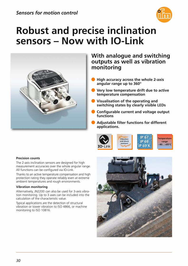
With analogue and switchingoutputs as well as vibrationmonitoring
Precision countsThe 2-axis inclination sensors are designed for highmeasurement accuracies over the whole angular range.All functions can be configured via IO-Link.Thanks to an active temperature compensation and highprotection rating they operate reliably even at extremeambient temperatures and rough environments.
Vibration monitoringAlternatively, JN2200 can also be used for 3-axis vibra-tion monitoring. Up to 3 axes can be included into thecalculation of the characteristic value.Typical applications are the detection of structural vibration or tower vibration to ISO 4866, or machinemonitoring to ISO 10816.
High accuracy across the whole 2-axisangular range up to 360°
Very low temperature drift due to activetemperature compensation
Visualisation of the operating andswitching states by clearly visible LEDs
Configurable current and voltage outputfunctions
Adjustable filter functions for differentapplications.
Robust and precise inclinationsensors – Now with IO-Link
Sensors for motion control

31
(11.2015)
9075
224562
5,3
364,
5
Operating voltage [V DC]with:Switching and current outputsVoltage outputIO-Link connection
9.2...3012...3018...30
Reverse polarity protection •
Angular rangeAbsolute accuracyRepeatabilityResolution
JN2200±180°/± 90°
≤ ± 0.5°≤ ± 0.1°≤ ± 0.05°
JN2201± 45°
≤ ± 0.1°≤ ± 0.05°≤ ± 0.01°
Ambient temperature [°C] -40...85
Temperature coefficient [°/K] ≤ ± 0.002
Protection rating IP 65 / IP 67 / IP 68 / IP 69K
Number of measurement axes with inclination 2
Frequency range [Hz] 0.1...400
Measuring range [g] ± 2, ± 4, ± 8
2
0.5...50
± 2
Number of measurement axes with vibration 3 –
Housing material diecast zinc nickel-plated
Connection2 x
M12 connector(4 poles; A-coded)
Technical dataJN2200, JN2201
Inclination sensors
Connection technology
Type Description Orderno.
Socket, M12,2 m black, PUR cable EVM039
Socket, M12,10 m black, PUR cable EVM041
Socket, M12,2 m black, PUR cable EVM036
Socket, M12,10 m black, PUR cable EVM038
Jumper, M12,5 m black, PUR cable EVC069
Jumper, M12,5 m black, PUR cable EVC059
Accessories
Description Orderno.
Dimensions
Type
For further technical details please visit: www.ifm.com
Sensors for motion control
The products
Description Orderno.
Angular range ± 180° / ± 90°,IO-Link JN2200
Angular range ± 45°,IO-Link JN2201
Type
Communication interfaceIO-Link 1.1,
COM 2,38.4 kbaud
LINERECORDER SENSORSoftware for parameter setting and set-up of IO-Link sensors
QA0001
USB IO-Link master for parameter settingand analysis of unitsSupported communication protocols: IO-Link (4.8, 38.4 and 230 kBit/s)
E30390
Memory plug, parameter memoryfor IO-Link sensors E30398

32
True 3D vision sensor with intelligent functions
Mobile 3D smart sensors O3MThe 3D detection of scenes and objects, already a standard on the factory floor, is ready for mobile machines. Apart from new possibilities for vehicle automation (AGV, automatic guided vehicles) this results in new assistance functions for automation tasks.Different integrated functions configurable via the Windows software are available as standard.The simple connection of the 3D smart sensors is carried out via the CAN bus for mobile applications using theCANopen or SAE J 1939 protocol and/or via the fastEthernet interface using UDP.
Simple application solutions thanks to preprocessed 3D data
Easy integration via predefined CODESYSfunction blocks
Patented pmd time-of-flight technologyfor quick distance detection
Optimised for reliable outdoor use with IP 67 and IP 69K
Angle of aperture up to 95°
3D Smart Sensor – your assistanton mobile machines
Industrial imaging
33
(04.2016)
Camera systems for mobile machines
Description Orderno.
IR system illumination unit (850 nm) for mobile 3D sensors, angle of aperture 70 x 23 O3M950
IR system illumination unit (850 nm) for mobile 3D sensors, angle of aperture 95 x 32 O3M960
Further technical dataSmart sensors O3M151, O3M161
Accessories
Housing material diecast aluminium
Device connection M12 connector
Protection rating, protection class
IP 67 / IP 69K, III
Operating voltage [V DC] 9...32
Functions and advantages
Powerful 3D time-of-flight measurement (ToF)The principle of these 3D sensors is based on ifm’s patented and award-winning pmd technology. It was specifically designed for outdoor use and difficultambient light situations. Even interference such as sun-light or materials with different reflective characteristicsdo not influence the repeatability of the measured data.Powerful electronicsThe integrated 2 x 32-bit processor architecture ensuresa rapid and reliable calculation of the 3D data andfunctions directly integrated in the system with up to50 fps. The complete electronics of the mobile 3D smart sensor is optimised and adapted to the demands andrequirements of mobile machines. Besides shock and vibration resistance self-diagnosticfunctions from the sensor to the IR system illuminationunit are of course also available.Smart functionsThe mobile 3D smart sensors integrate some functionswhich enable to solve a multitude of applications. A highly developed algorithm from the automotive industry is used ensuring, for example, reliable automatic object recognition of up to 20 objects. This functioncan, for example, be used as collision warning. For simple distance tasks typical functions such as minimum / maximum / average distance are available.System parameter setting and monitoringThe parameter setting of the system and live monitoring of the 3D data are carried out via the easy-to-use ifmvision wizard for Windows. As an alternative, parameter setting can also be carried out via function blocks usingthe software CODESYS.Communication interfacesThe preprocessed function data is output via the CANbus using CANopen or SAE J 1939. If needed, the complete 3D information can be processed at the sametime via Ethernet UDP and an external process unit.
Current consumption sensor [mA] < 400
Current consumption [A]system illumination unit < 5
Ambient temperature [°C] -40...85
Interfaces 1x CAN, 1 x fast Ethernet
Supported CAN protocols CANopen, SAE J 1939
Standards and tests (extract)
CE,E1 (UN-ECE R10)
For further technical details please visit: www.ifm.com
Industrial imaging
CAN/RS232 USB interface CANfox EC2112
Adapter cable set for CANfox EC2114
Operating software for vision sensors E3D300
U-shaped holder, suitable for sensor or illumination unit E3M100
Connection technology
MCI cable, connection sensor / system illumination unit, 1 m E3M121
MCI cable, connection sensor / system illumination unit, 2 m E3M122
Type Description Orderno.
M12 socket, voltage supply system illumination unit, 2 m, PUR cable, 4 poles
E3M131
M12 socket, voltage supply system illumination unit, 10 m, PUR cable, 4 poles
E3M133
Ethernet, cross-over patch cable,2 m, PVC cable, M12 / RJ45 E11898
Ethernet, cross-over patch cable,10 m, PVC cable, M12 / RJ45 E12204
Type of sensor Resolution pixels [pixel]
IlluminationAngle of aperturehorizontal x vertical
[°]
Orderno.
PMD 3D sensor · Type O3M · M12 connector
PMD 3D chip 64 x 16 ext. illumination required (O3M950)70 x 23 O3M151
Max. sampling rate
[Hz]
25/33/50
PMD 3D chip 64 x 16 ext. illumination required (O3M960)95 x 32 O3M16125/33/50

34
True 3D vision sensor
Mobile 3D sensors O3MThe 3D detection of scenes and objects, already a standard on the factory floor, is ready for mobile machines. Apart from new possibilities for vehicle automation (AGV, automatic guided vehicles) this results in new assistance functions for automation tasks.Besides position data at pixel level the respective distance to the sensor system or an adjustable reference point (world coordinate system) is provided. Thanks tothe permanent output of the entire 3D information viaEthernet UDP optimum conditions for customer-specificapplication solutions are provided to system integrators.
Support for system integrators with data output via Ethernet UDP
Patented pmd time-of-flight technologyfor quick distance detection
Optimised for reliable outdoor use
Robust design with IP 67 and IP 69K
Angle of aperture up to 95°
3D sensors for mobile machines
Industrial imaging
35
(04.2016)
Camera systems for mobile machines
Further technical dataO3M150, O3M160
Housing material diecast aluminium
Device connection M12 connector
Protection rating, protection class
IP 67 / IP 69K, III
Operating voltage [V DC] 9...32
Functions and advantages
Powerful 3D time-of-flight measurement (ToF)The principle of these 3D sensors is based on ifm’s patented and award-winning pmd technology. It was specifically designed for outdoor use and difficultambient light situations. Interference such as sunlightor materials with different reflective characteristicswhich occurs in the area of mobile machines does notinfluence the repeatability of the measured data.
Powerful electronicsThe integrated 2 x 32-bit processor architecture ensuresa rapid and reliable calculation of the distance image tobe output with up to 50 fps. The complete electronicsof the mobile 3D sensor is optimised and adapted to the demands and requirements of mobile machines. Besides shock and vibration resistance self-diagnosticfunctions from the sensor to the IR system illuminationunit are of course also available.
High system uptimeThe system has various features to ensure uninterrupted operation. They include, among others, soiling indication as well as different status information which can be fetched from CAN.
System parameter setting and monitoringThe parameter setting of the system and live monitoring of the 3D data are carried out via the easy-to-use ifmvision wizard for Windows.
Communication interfacesThe mobile 3D sensors feature a fast Ethernet interface (100 Mbit) as well as a CAN interface. The data outputof the complete 3D information is carried out via Ethernet UDP and can be processed using a processunit at the customer’s end. For this version the CAN in-terface is only intended for parameter setting and status output.
Current consumption sensor [mA] < 400
Current consumption [A]system illumination unit < 5
Ambient temperature [°C] -40...85
Interfaces 1x CAN, 1 x fast Ethernet
For further technical details please visit: www.ifm.com
Industrial imaging
Connection technology
MCI cable, connection sensor / system illumination unit, 1 m E3M121
MCI cable, connection sensor / system illumination unit, 2 m E3M122
Type Description Orderno.
M12 socket, voltage supply system illumination unit, 2 m, PUR cable, 4 poles
E3M131
M12 socket, voltage supply system illumination unit, 10 m, PUR cable, 4 poles
E3M133
Ethernet, cross-over patch cable,2 m, PVC cable, M12 / RJ45 E11898
Ethernet, cross-over patch cable,10 m, PVC cable, M12 / RJ45 E12204
Type of sensor Resolution pixels [pixel]
IlluminationAngle of aperturehorizontal x vertical
[°]
Orderno.
PMD 3D sensor · Type O3M · M12 connector
PMD 3D chip 64 x 16 ext. illumination required (O3M950)70 x 23 O3M150
Max. sampling rate
[Hz]
25/33/50
PMD 3D chip 64 x 16 ext. illumination required (O3M960)95 x 32 O3M16025/33/50
Description Orderno.
IR system illumination unit (850 nm) for mobile 3D sensors, angle of aperture 70 x 23 O3M950
IR system illumination unit (850 nm) for mobile 3D sensors, angle of aperture 95 x 32 O3M960
Accessories
Supported CAN protocols CANopen, SAE J 1939
Standards and tests (extract)
CE,E1 (UN-ECE R10)
CAN/RS232 USB interface CANfox EC2112
Adapter cable set for CANfox EC2114
Operating software for vision sensors E3D300
U-shaped holder, suitable for sensor or illumination unit E3M100

36
Innovative operating conceptsfor intuitive handling
Incomplete shipments – never againIf a pallet with only one incomplete handling unit reaches the customer, he often returns all goods. This does not only lead to dissatisfaction but also to additional costs. Completeness monitoring provides theremedy. Often individual sensors are installed aboveeach individual handling unit position. This is, however,not very flexible if the handling unit type or size changes. Then changes become necessary. If colour or texture ofthe handling units change, conventional sensors reachtheir limits.All these problems are unknown to completeness monitoring on the basis of 3D sensors: The 3D sensorlooks at the handling unit from above and compares it with the models taught in by the user. It signals anydeviation via a switching output.Continuous exchange with users and extensive hand-ling tests have lead to extraordinarily simple operationand integrability of the sensor.
Different handling units can be taught
Reliable detection of underfill or overfill
Automatic position tracking
Colour-independent and extraneous-lightresistant due to time-of-flight technology(PMD).
Switching outputs and Ethernet processdata interface
Completeness monitoring for thepackaging technology
Industrial imaging
37
(11.2015)
3D sensors
Further technical data
Operating voltage [V DC] 20.4...28.8
Current consumption [mA]
< 2400 peak current pulsed;
typ. mean value 420
Current rating [mA](per switching output) 100
Real chip resolution 25,000 / 100,000
Resulting resolution 176 x 132 pixels
Function display LED 2 x yellow,2 x green
Illumination 850 nm,infrared
Ambient light [lux] Max. 10,000 (indoor)
Trigger
External; 24 V PNP/NPN according to
IEC 61131-2 type 3
Switching inputs
2 (configurable), 24 V PNP/NPNaccording to
IEC 61131-2 type 3
Switching outputs
3 (configurable), 24 V PNP/NPN, according to IEC 61131-2
Ambient temperature [°C] -10...50
For further technical details please visit: www.ifm.com
Industrial imaging
Type of sensor Materialfront pane /LED window
Angle of aperture
[°]
Protection rating,protection class
Orderno.
PMD 3D sensors · Type O3D · M12 connector
PMD 3D ToF chip Gorilla glass /polyamide
Materialhousing
Aluminium 40 x 30IP 65 / IP 67,III O3D300
Max.field of view size
[m]
2.61 x 3.47
PMD 3D ToF chip Gorilla glass /polyamideAluminium 60 x 45IP 65 / IP 67,
III O3D3023.75 x 5.00
PMD 3D ToF chip Polycarbonate /polyamideStainless steel 40 x 30IP 66 / IP 67,
III O3D3102.61 x 3.47
PMD 3D ToF chip Polycarbonate /polyamideStainless steel 60 x 45IP 66 / IP 67,
III O3D3123.75 x 5.00
Short-circuit protection, pulsed •
Overload protection •
Parameter setting interface Ethernet 10 Base-T /100 Base-TX
Possible parameter settings Via PC / notebook
Dimensions (H, W, D) [mm] 72 x 65 x 85
Technical data Completeness monitoring
Operating distance [m] 0.3...5
Max. handling unit size 64 objects
Sampling rate / [Hz]switching frequencyThe image repetition frequency is reduced by using the position trackingfunction
10
Minimum size of objects [mm]Object speed: 0...0.2 m/sObject speed: > 0.2 m/s
2545
Ethernet, cross-over patch cable,2 m, PVC cable, M12 / RJ45
Ethernet jumper,2 m, PVC cable, M12 / M12
Socket, M12,2 m black, PUR cable, 8 poles
Type Description Orderno.
Mounting set for O3D E3D301
Accessories
E11898
E21138
E11950
Cooling element E3D302
Double cooling element E3D304
Heat conductor E3D303
Mounting accessories
Connection technology

38
Flexible and universal use forstationary or moving objects
The revolution in intralogisticsWhether pallets, post room, storage building, logisticsor distribution centre: The storage volume that can beused defines the capacity and the costs. A good reason to ensure the best-possible use of thespace requirement during feeding.The new 3D sensor detects the dimensions of thegoods via innovative time-of-flight technology. It signals via threshold values if e.g. package parameters are out-side the defined areas.For automated storage space planning via WMS (Warehouse Management System) or ERP system (Enterprise Resource Planning) it provides the size, ori-entation and position of the objects. The data is alsoused for controlling robots, sorting equipment and distribution gates. Besides robustness the sensor is also distinguished by user-friendly handling and simpleintegration.
Non-contact dimensioning of rectangular objects such as cardboard packages or parcels
Determination and comparison of dimensions, orientation and position
Provides height, width and length to calculate strap length and volume
Quality parameters help with the detection of damaged or deformed objects
Switching outputs and Ethernet processdata interface
Volume determination for storage and conveyor technology
Industrial imaging

39
(11.2015)
3D sensors
Further technical data
For further technical details please visit: www.ifm.com
Industrial imaging
Ethernet, cross-over patch cable,2 m, PVC cable, M12 / RJ45
Ethernet jumper,2 m, PVC cable, M12 / M12
Type of sensor Materialfront pane /LED window
Angle of aperture
[°]
Protection rating,protection class
Orderno.
PMD 3D sensors · Type O3D · M12 connector
PMD 3D ToF chip Gorilla glass /polyamide
Materialhousing
Aluminium 40 x 30IP 65 / IP 67,III O3D300
Max.field of view size
[m]
2.61 x 3.47
PMD 3D ToF chip Gorilla glass /polyamideAluminium 60 x 45IP 65 / IP 67,
III O3D3023.75 x 5.00
PMD 3D ToF chip Polycarbonate /polyamideStainless steel 40 x 30IP 66 / IP 67,
III O3D3102.61 x 3.47
PMD 3D ToF chip Polycarbonate /polyamideStainless steel 60 x 45IP 66 / IP 67,
III O3D3123.75 x 5.00
Socket, M12,2 m black, PUR cable, 8 poles
Type Description Orderno.
Technical data Dimensioning of the object
Operating distance [m] 0.3...5
Object type Rectangular
Min. object size [mm] 100 x 100 x 100
Typical accuracy [°]for angle of rotation ± 1
Sampling rate / switching frequency [Hz] 1
Typical accuracy [mm]for object position ± 5
Object speed [m/s] < 0.2
Typical accuracy [mm]for object size ± 10
Operating voltage [V DC] 20.4...28.8
Current consumption [mA]
< 2400 peak current pulsed;
typ. mean value 420
Current rating [mA](per switching output) 100
Real chip resolution 25,000 / 100,000
Resulting resolution 176 x 132 pixels
Function display LED 2 x yellow,2 x green
Illumination 850 nm,infrared
Ambient light [lux] Max. 10,000 (indoor)
Trigger
External; 24 V PNP/NPN according to
IEC 61131-2 type 3
Switching inputs
2 (configurable), 24 V PNP/NPNaccording to
IEC 61131-2 type 3
Switching outputs
3 (configurable), 24 V PNP/NPN, according to IEC 61131-2
Ambient temperature [°C] -10...50
Short-circuit protection, pulsed •
Overload protection •
Parameter setting interface Ethernet 10 Base-T /100 Base-TX
Possible parameter settings Via PC / notebook
Dimensions (H, W, D) [mm] 72 x 65 x 85
Mounting set for O3D E3D301
Accessories
E11898
E21138
E11950
Cooling element E3D302
Double cooling element E3D304
Heat conductor E3D303
Mounting accessories
Connection technology

40
Three-dimensional real-timedetection of any scene
Perspective and colour-coded images of the 3D distance image.
Three-dimensional detection and evaluationThe 3D camera, on the basis of PMD technology, detects scenes and objects at a glance in three dimensions. In contrast to laser scanners it does not require movingcomponents and is thus robust and wear-free. The function principle, the time of flight technology(ToF), can be compared to a laser scanner. However, instead of one there are 23,000 receiving elements arranged on the chip as a matrix. That means that notonly one point but a complete scene is measured inonly one capture. Besides the distance image the camera also provides a grey-scale image of the scene.Intuitive parameter setting software allows easy settingof the camera-specific parameters. Furthermore a soft-ware development kit with example program code indifferent languages is available.
New digital image chip with 23,000 pixels
Provides distance image and grey-scale image
Evaluation with common image processing libraries
Industrially compatible housing
Connection to MATLAB, HALCON, PCL(Point Cloud Library) and ROS (Robot Operating System)
High-resolution 3D camera for innovative vision integration
Industrial imaging

41
(11.2015)
3D cameras
Further technical data
Operating voltage [V DC] 24
Current consumption [mA] < 1000 (max. 2500)
Current rating [mA](per switching output) 100
Range [m] Typically 5
Unambiguous range [m] 0...30
Sampling rate / [Hz]switching frequency
Max. 20, adjustable
Resolution 176 x 132 pixels
Function display LED 2 x yellow,2 x green
Illumination 850 nm,infrared
Ambient light [lux] Max. 10,000 (indoor)
Trigger
Internal or external: 24 V PNP / NPN selectable,
according to IEC 61131-2 type 2
Switching inputs
Max: 2 (configurable), 24 V PNP / NPN selectable,
according to IEC 61131-2 type 2
Switching outputs
Max: 2 (configurable), 24 V PNP / NPN selectableor 1 analogue output (con-figurable) scalable, 4...20
mA according to IEC 61131-2,
max. load 300 Ω, 0...10 V according to
IEC 61131-2, min. load 10 kΩ
Ambient temperature [°C] -10...50
For further technical details please visit: www.ifm.com
Industrial imaging
PMD 3D camera · Type O3D · M12 connector
Socket, M12,2 m black, PUR cable, 5 poles EVC070
socket, M12,5 m black, PUR cable, 5 poles EVC071
Short-circuit protection •
Overload protection •
Parameter setting interface Ethernet 10 Base-T /100 Base-TX
Possible parameter settings Via PC / notebook
Type of sensor Materialfront pane /LED window
Angle of aperture
[°]
Protection rating,protection class
Orderno.
Infineon® 3D Image Sensor
Gorilla glass /polyamide
Materialhousing
Aluminium 40 x 30IP65 / IP67,III O3D301
Max.field of view size
[mm]
2.61 x 3.47
Infineon® 3D Image Sensor
Gorilla glass /polyamideAluminium 60 x 45IP65 / IP67,
III O3D3033.75 x 5.00
Infineon® 3D Image Sensor
Polycarbonate /polyamideStainless steel 40 x 30IP66 / IP67,
III O3D3112.61 x 3.47
Infineon® 3D Image Sensor
Polycarbonate /polyamideStainless steel 60 x 45IP66 / IP67,
III O3D3133.75 x 5.00
Ethernet, cross-over patch cable,2 m, PVC cable, M12 / RJ45
Ethernet jumper,2 m, PVC cable, M12 / M12
Type Description Orderno.
Mounting set for O3D E3D301
Accessories
E11898
E21138
Cooling element E3D302
Double cooling element E3D304
Heat conductor E3D303
Mounting accessories
Connection technology

42
Pressure transmitters with M12, AMP or DEUTSCH connectorfor mobile applications
Miniaturisation for mobile applicationsThe connectors of the new PT/PU pressure sensorsallow fast and easy installation in mobile machines.The sensors also feature a thin-film measuring cell directly welded with the process connection. This technology guarantees high accuracy in a verycompact housing with only 19 mm across flats at acost-optimised price /performance ratio.
ApplicationsThe PT/PU type sensors are suited for mobile applica-tions and especially for hydraulic and pneumatic appli-cations with high operating pressure.The high vibration and shock resistance, the high protection rating, the excellent EMC resistance and theE1 conformity make the PT/PU sensors particularly suitable for use in mobile machines.
Compact design (AF19) with process connection G 1/4 male
Fast reaction: 2 milliseconds response time
Measuring accuracy < ± 0.8 %, repeatability < ± 0.05 %
Easy connection via DEUTSCH, AMP or M12 connector
Robust low-cost solution with welded stainless steel housing
Small and cost-optimised for mobile machines
Process sensors

43
(04.2016)
Pressure sensors
Accessories
Type Description Orderno.
Operating voltage PT [V DC]PU [V DC]
8...3216...32
Common technical data
Medium temperature [°C] -40...125
Materials wetted parts
1.4542 (17-4 PH / 630),characteristics similar to
stainless steel (e.g. 304/1.4301)
but higher strength
Protection IP 67 / IP 69K
Step response time [ms] 2
Restrictor •
EMC
Compliant with UN-ECE10Rev. 4
ISO 11452: 100 V/mEN61326
Reverse polarity protection •
Adapters; G 1/4 - G 1/2, high-grade stainless steel (316Ti/1.4571) E30135
For further technical details please visit: www.ifm.com
Process sensors
Accuracy / deviation(in % of the span)Linearity errorLinearityHysteresisRepeatabilityLong-term stabilityTemperature coefficients (TEMPCO)in the temperature range 0 ... 80 °C(in % of the span per 10 K)TEMPCO of zeroTEMPCO of the spanTemperature coefficients (TEMPCO)in the temperature ranges -40...0 °C and 80...125 °C(in % of the span per 10 K)TEMPCO of zeroTEMPCO of the span
< ± 0.8< ± 0.25 BFSL / < ± 0.5 LS
< ± 0.2< ± 0.05< ± 0.1
< ± 0.1< ± 0.1
< ± 0.2< ± 0.2
Wiring diagram
Dimensions
12
65,9
51,6
M12 x118,9
G1 4/19
1
Example: type PT55
1) HNBR seal / DIN 3869
PU5704
PU5703
PU5702
PU5701
PU5700
PU5760
PU5604
PU5603
PU5602
PU5601
PU5600
PU5660
Measuring rangerelative pressure
[bar]
Poverloadmax.[bar]
Pburstmin.[bar]
Output function 4…20 mA,
0...10 25 300
0...25 65 600
0...100 250 1000 PT5702
0...250 625 1200 PT5701
0...400 1000 1700 PT5700
0...600 1500 2400 PT5760
Output function 0...10 V
0...10 300
0...25 600
0...100 1000
PT5602
0...250 1200
PT5601
0...400 1700
PT5600
0...600 2400
PT5660
PT5502
PT5501
PT5500
PT5560
25
65
250
625
1000
1500
Orderno.
PT5504
M12 connector
PT5503
Orderno.
PT5604
AMP connector
PT5603
Orderno.
PT5704
DEUTSCH connector
M12 connector AMP connector DEUTSCH connector
PT5703
L+BN1
WH2 OUT
Type PT55
1
2
3OUT
L +
L -
Type PU56
A
B OUT
+L A
C
BOUT
L -
L +L +
Type PU57Type PT57
1
3 L +
OUT
Type PT56
–
–
–
–
–
–

44
Process sensors
High-grade stainless steel submersible pressure transmit-ter of different cable materials
Level measurement in a water treatment plant
Application areasThe PS series submersible pressure transmitters are used for level measurement in containers, tanks, wells,flowing water, bore holes and wastewater plants. Theaccuracy of 0.5 % and the long-term stability of 0.2 %per year contribute to the reliable operation of thetransmitter.
Robust, reliable and flexibleAll submersible pressure transmitters have a robusthigh-grade stainless steel housing. For standard applica-tions the favourably priced PUR cable can be used. For applications where a high resistance to media is requested (e.g. slurry, oils or fuels) the FEP cable is available. The ATEX submersible pressure transmitters of thePS3xxA series are designed for level measurement inareas subject to explosion. The sensors can be used inzone 0, 1, 2 or zone 20, 21, 22 as well as in mining.The GL approval allows an application in the maritimesector.
PUR or FEP cable for high resistance to media
Version with ATEX approval for group Icat. M1 and group II cat. 1G and 1D.
Good overall accuracy and long-term stability
Pressure compensation via internally vented cable
Hydrostatic level measurement for a wide range of applications

45
(04.2016)
Process sensors
For further technical details please visit: www.ifm.com
Pressure sensors
Splitter box *with vent and terminal block E30401
Additional weight, approx. 500 g E30402
Filter element * E30400
Cable fixing clamps * E30399
Submersible pressure transmitters with PUR cable for standard applications
0.6
0.6
0.6
4
4
4
1000 N
1000 N
1000 N
Measuring rangeRelative pressure
[bar]
ApprovalsCE / EX / GL
Overload pressure
[bar]
Pull force cable
1
1
5
5
1000 N
1000 N
Cable length
[m]
PS3407
PS3427
PS3607
Orderno.
PS3417
PS3617
0.25 2 1000 N
10
15
30
15
30
5
• / – / –
• / – / –
• / – / –
• / – / –
• / – / –
• / – / – PS3208
Operating voltage [V DC] 18...30
Analogue output [mA] 4...20
Accuracy / deviation(in % of the span)Accuracy (BFSL)Accuracy incl. non-linearityNon-linearity (BFSL)Long-term stability per year
≤ 0.25 (PS3: 0.5)≤ 0.5 (PS3: 1)
≤ 0.2≤ 0.2
Design PS3Ambient temperature / [°C]Medium temperature
-10...50
Design PS4Ambient temperature / [°C]Medium temperature
-10...85
Design PS3 ATEX approvalAmbient temperature / [°C]Medium temperature
1G, 1/2G, 2G:T6 -10...60, T5: -10...80,
T4: -10...851D, 1/2D, 2D:
-10...40 (750 mW) / -10...70 (650 mW) / -
10...85 (550 mW)
Housing material High-grade stainless steel (316Ti / 1.4571)
Further technical data
Accessories
Type Description Orderno.
* use only outside the hazardous area
Submersible pressure transmitters with FEP cable for high resistance to media
0.6
1
3
5
500 N
500 N
PS4407
PS4417
0.25 2 500 N
10
15
5
• / – / –
• / – / –
• / – / – PS4208
Submersible pressure transmitters with FEP cable for hazardous areas
0.6
1
4
5
500 N
500 N
PS307A
PS317A
0.25 2 500 N
10
15
5
• / • / •
• / • / •
• / • / • PS308A
Temperature coefficients (TEMPCO)(in % of the span per 10 K)Greatest TEMPCO of zeroGreatest TEMPCO of the span
≤ 0.2≤ 0.2
100
27
Example PS3208
Dimensions
0.6
1
3
5
500 N
500 N
PS4506
PS4607
0.25 2 500 N
20
30
10
• / – / –
• / – / –
• / – / – PS4408

46
New PT absolute pressuretransmitter with differentmeasuring ranges
Absolute pressure sensorsAs of now, ifm has added absolute pressure sensors toits versatile portfolio in the pressure sensor range. The new PT05 series with robust metal measuring cell,G 1/4 process connection, M12 connector and analogue output is available in the common pressure ranges upto 10 bar.
Operating principleAbsolute pressure sensors operate independently of thesurrounding air pressure; that is what distinguishesthem from sensors working on a relative measurementprinciple. The measurement is not influenced by weather- and altitude-related fluctuations of air pressure. This isoften a decisive factor in vacuum applications, whichrequire a fine pressure control.Absolute pressure sensors do not require ventilation,therefore incorrect measurement due to a blocked exhaust is impossible. In the field of pressure sensors the new units stand outas specialists for ”specific duties“.
Measuring range 0...1/1,6/4/10 bar absolute and analogue output 4...20 mA
Robust stainless steel measuring cell
Slim, compact design with G 1/4 processconnection
Measuring accuracy ≤ 0.8 %, repeatability ≤ 0.1 %
Easy connection via M12 connector
From now on, measure pressure absolutely!
Process sensors

47
(04.2016)
Pressure sensors
Accessories
Type Description Order no.
Operating voltage [V DC] 8...30
Common technical data
Medium temperature [°C] 0...80
Materials (wetted parts)NBR,
high-grade stainless steel(316L/1.4404)
Protection IP 67
Step response time [ms] 4
Reverse polarity protection •
Adapter; G 1/4 - G 1/2, high-grade stainless steel (316Ti/1.4571) E30135
For further technical details please visit: www.ifm.com
Process sensors
Measuring range
[bar]
Poverloadmax.[bar]
Pburstmin.[bar]
Order no.
Output function 4...20 mA
0...1 5 PT0507
0...1.6 10 PT0517
0...4 25 PT0505
0...10 50 PT0504
Accuracy / deviation(in % of the span)Linearity errorLinearityRepeatabilityTemperature error in the temperature range 0...80 °C
< ± 1.0< ± 0.5 BFSL / < ± 1.0 LS
< ± 0.1< ± 2.5 %
Connection technology
Type Description Order no.
M12 socket,2 m black, PUR cable EVC001
M12 socket,5 m black, PUR cable EVC002
M12 socket,2 m black, PUR cable EVC004
M12 socket,5 m black, PUR cable EVC005
L+BN1
WH2 OUT
Wiring diagram
Dimensions
1447 58
,8G¼
29M12 x1
27
1
1) Sealing
2
3.2
8
20

48
More plant transparency andservice information on site
More plant transparencyThe IO-Link display is a flexible solution to display process values, texts and messages in a plant. It displays up tofour assigned process values, alarms and warnings.Clear text and as an option a colour change of text andbackground can be used for a quick overview. By means of buttons the user can trigger control actions of the PLC or acknowledge messages.
Easy integrationThe IO-Link display is connected to an IO-Link masterand controlled via PLC. No special software is requiredfor configuration. Texts and settings can be predetermined via an IO-Linkdevice tool such as LINERECORDER SENSOR. Texts andsettings can be adapted even during operation via thePLC.
Four measured values / text displays andfour message windows for free text
Colour change for text and background
Flexible adaptation of the display, alsoduring operation
IO-Link 1.1 compatible
Easy integration into each IO-Link structure
IO-Link display: process values at a glance
Process sensors

49
(11.2015)
IO-Link display
For further technical details please visit: www.ifm.com
Process sensors
Resolution pixels
Display type Displayillumination
Orderno.
1.44“ colour display
128 x 128 TFT LED E30391
Wiring
Dimensions
Technical data
IO-Link displayE30391
Operating voltage [V DC] 18...30
Current consumption [mA] < 47
Protection rating / protection class
IP 65, IP 67 / III
Reverse polarity protection •
Ambient temperature [°C] 0...60
EMC EN 61000-6-2 EN 61000-6-4
Shock resistance [g] 20 (11 ms)
Vibration resistance [g] 20 (10...50 Hz)
Housing materials
Stainless steel (303/1.4305); PC; PBT-GF 30;
PPS; PA 6.6; FKM
Connection M12 connector
Communication interfaceIO-Link deviceType of transmissionIO-Link revisionSDCI standard
COM2 (38.4 kbaud)1.1
IEC 61131-9
Connection technology
Type Description Orderno.
M12 jumper1 m black, PUR cable EVC042
M12 jumper2 m black, PUR cable EVC043
M12 jumper, 3 m black, PUR cable EVC102
M12 jumper, 5 m black, PUR cable EVC044
M12 jumper, 10 m black, PUR cable EVC493
BN1
BK4
BU3
L+
L
OUT
45 34
86
101
39,5
11M
12x1

50
Calorimetric flow meter for liquids and gases
Measurement techniqueThe SA volumetric flow sensor operates using the calorimetric measuring principle. Measuring elementsas well as a heat source are located on the measuringtip. The physical effect that a flowing medium absorbsheat energy and conducts it away is used. The resultingtemperature change is an indication of flow.
Device functionThe new SA-type sensor has been designed to detectand measure flow and temperature even in large internal pipe diameters up to 400 mm. A serial number on the device enables unambiguous traceability.Therefore it serves different applications. Switching outputs, analogue signals and IO-Link provide variousoptions to further process the signals. That means thatthe user is best-equipped for Industry 4.0.
Optimised for water, oils, glycol and air
Fast response time and integrated temperature measurement
Red/green colour change for process values
Internal pipe diameter selectable from15...400 mm
The process connection can be rotated foroptimum alignment
New benchmark in thermal flowmeasurement
Process sensors

51
(11.2015)
Flow sensors / flow meters
For further technical details please visit: www.ifm.com
Common technical data
Operating voltage [V] 18...30 DC
Current consumption [mA] < 100
Current rating [mA] 250
Housing materials
High grade stainless steel (1.4404/316L);
PBT-GF 20; PBT-GF 30
Connection M12 connector
Accuracy temperature measurement ± 0.3 K
TypeSA
Protection rating, protection class IP 65 / IP 67, III
BN
WH
BK
BU
4
1
3
2 OUT2
L+
L
OUT1
Wiring
Measuring rangeliquid / gaseous
[cm/s]
Mediumtemperature
[°C]
Response time[s]
Orderno.
M12 connector · electrical design DC PNP
5...300 / 200...10000 -20...90 0.5 SA5000
Probe length
[mm]
45
5...300 / 200...10000 -20...100 0.5 SA4100100
5...300 / 200...10000 -20...100 0.5 SA4300200
Pressure resistance
[bar]
100
50
50
Process sensors
Type
M18
Progressive ring
Progressive ring
Connection technology
Type Description Orderno.
M12 socket,2 m black, PUR cable EVC001
M12 socket,5 m black, PUR cable EVC002
M12 socket,2 m black, PUR cable EVC004
M12 socket,5 m black, PUR cable EVC005
M12 socket,2 m orange, PVC cable EVT064
M12 socket,5 m orange, PVC cable EVT001
Accuracy flow measurement
± (5 % MW + 2 % VMR) at referenceconditions
Accessories
Type Description Orderno.
Progressive ring fitting G 1/2, flat seal E40258
Progressive ring fitting G 1/4, flat seal E40259
Progressive ring fitting G 3/4, flat seal E40260
USB IO-Link master for parameter settingand analysis of unitsSupported communication protocols: IO-Link (4.8, 38.4 and 230 Kbits/s)
E30390
Progressive ring fitting 1/2 NPT E40261
Progressive ring fitting 1/4 NPT E40262
Progressive ring fitting R 1/2 E40263
Progressive ring fitting R 1/4 E40264
Progressive ring fitting for SL mounting adapter E40269
Protective cover for fluid sensors with M12 connector,polypropylene homopolymer
E30420
Welding adapter for cutting ring E40265

52
Compact mechatronic inlineflow meter with backflowprevention
Mechatronic flow sensorThe new mechatronic flow sensor of the SBY seriesfunctions using the principle of a spring-mounted piston. The piston, located in the valve seat in the housing, is lifted by the flowing medium against the spring resistance.For binary signal output the piston position is detectedby an inductive sensor. The spring resistance leads toreliable reset of the piston to its initial position with decreasing flow. This ensures position-independent installation of the flow sensor preventing backflow.The switch points can be easily set and fixed via a setting screw. The robust mechanical design ensuresuse in harsh environments. The units are maintenance-free.
Measuring range from 0.2...4 l/min
Compact design
Very fast response time of ≤ 10 ms
No inlet and outlet pipe lengths required
Independent of pressure and temperaturefluctuations
New flow sensor now also forsmallest quantities
Process sensors

53
(11.2015)
Flow sensors / flow meters
For further technical details please visit: www.ifm.com
Current consumption [mA] < 15
Ambient temperature [°C] 0...60
Protection rating, protection class IP 65 / IP 67, III
Housing materials
Brass chemically nickel-plated;
anodised aluminium; PA
Materials in contact with the medium
High-grade stainless steel(301/1.4310);
high-grade stainless steel(316/1.4401);
PBT; brass chemically nickel-plated; PPS;
O-ring: FKM Polyolefin
Short-circuit protection •
Further technical data
Overload protection •
L+
L
BN1
4 BK
3 BU
Wiring
Process connection
Pressure resistance
[bar]
Measuring range
[l/min]
Response time
[ms]
Orderno.
M12 connector · electrical design DC PNP
Rp 1/2 800.2...4 ≤ 10 SBY321
Operating voltage
[V]
24 DC
Type
Connection technology
Type Description Orderno.
M12 socket,2 m black, PUR cable EVC001
M12 socket,5 m black, PUR cable EVC002
M12 socket,2 m black, PUR cable EVC004
M12 socket,5 m black, PUR cable EVC005
M12 socket,2 m orange, PVC cable EVT064
M12 socket,5 m orange, PVC cable EVT001
Process sensors
Connection M12 connector
M12
94...
99
27
Rp
½
Rp
½
66,518
107...113
13 13
Dimensions

54
Reliable level detection – LMT
Level detection in explosive atmospheresLMT sensors reliably detect levels in storage tanks in explosive areas. They can be used in zones 2 and 22.
Food-gradeThe sensor with its high-quality housing materials suchas high-grade stainless steel (316L / 1.4404) and PEEKmeets all requirements for hygienic areas. This includesapprovals such as EHEDG and FDA.
Versatile sensor for all mediaThe LMT can be adjusted to almost all liquid and viscous media as well as powders. The distinction between two media in the same applica-tion is possible due to the two switching outputs whichcan be set independently. Convenient parameter setting is made via IO-Link.
Approved for ATEX areas of category3D/3G
“Plug & Play“ – factory preset to oil-basedmedia
Can be set to other media such as alcoholusing IO-Link
Hygienic design with maintenance-freesealing concept
Shock and vibration resistant in a robuststainless steel housing
Hygienic point level sensor especially for hazardous areas
Process sensors

55
(11.2015)
Level sensors
Process connection
Installation length [mm]
Approval Protection
[hazardous areas]*
Orderno.
Application: liquids, viscous media and powdersM12 connection · output function 2 x NO/NC programmable · 4-wire DC PNP · IO-Link 1.1
Medium temperatureoils, oil-based media,
powder
G 1/2 12 EHEDG, FDA -20...85 °C IP 67 / III LMT01A
G 1/2 153 EHEDG, FDA -20...85 °C IP 67 / III LMT03A
G 1/2 253 EHEDG, FDA -20...85 °C IP 67 / III LMT04A
Accessories
Type DescriptionHigh-grade stainless steel
Orderno.
Current rating [mA] 100
Housing materials
high-grade stainless steel (1.4404 / 316L), (1.4571 / 316Ti),PEEK; PEI; FKM
Materials in contactwith the medium
high-grade stainless steel (1.4404 / 316L), (1.4571 / 316Ti),
PEEK; FKM
Shock resistance [g] 50
Vibration resistance [g](LMT03A, LMT04A) 8
Vibration resistance [g](LMT01A) 20
Ambient temperature [°C] -20...60
EMC (LMT03A, LMT04A)Closed tanks
EN 61000-6-2EN 61000-6-4
EMC (LMT01A)Open tanksClosed tanks
EN 61000-6-2EN 61000-6-4EN 61000-6-3
Operating voltage [V] 18...30 DC
Current consumption [mA] < 50
Further technical data
Clamp adapter G 1/2 female – Clamp 1“–1.5“ E33401
Clamp adapter G 1/2 female – Clamp 2“ E33402
Welding adapter ball, G 1/2 E30055
Welding adapter collar, G 1/2 E30056
Welding adapter,cylindrical, for tanks, G 1/2 E43300
Welding adapter,cylindrical, for pipes, G 1/2 E43301
Screw-in adapter G1/2 female – G 3/4 male E43302
Screw-in adapter G1/2 female – G 1 male E43303
Screw-in adapter G1/2 female – 3/4 NPT E43313
Clamp adapter, G 1/2 female – Varivent D50 E43306
Clamp adapter, G 1/2 female – Varivent D68 E43307
Accessories
Type Description Orderno.
IO-Link interface for parameter settingand analysis of units with DTM specification, current consumptionfrom USB port: max. 500 mA
E30396
Memory plug, parameter memoryfor IO-Link sensors E30398
T-piece, DN 25 E43316
T-piece, DN 40 E43317
T-piece, DN 50 E43318
For further technical details please visit: www.ifm.com
Welding adapter, long design for deeper installation, G 1/2 E43319
Process sensors
ATEX approval group II, category 3D / 3G
Communication interface IO-Link 1.1
Connection M12 connector
LINERECORDER SENSOR,Software for parameter setting and setting up IO-Link sensors
QA0001
USB IO-Link master for parameter settingand analysis of unitsSupported communication protocols: IO-Link (4.8, 38.4 and 230 Kbits/s)
E30390
*IP 68, IP 69K outside the hazardous area
Connection technology
Type Description Orderno.
Socket, M12,2 m black, PUR cable EVC04A
Socket, M12,5 m black, PUR cable EVC05A
Socket, M12,10 m black, PUR cable EVC06A

56
LR level sensor in a new design with extended functions
ApplicationHarsh environment conditions or high temperaturesleave the LR2050 cold. Installation in confined spacesor detection of oils using a coaxial pipe is no problemfor LR, either. LR flexibly adapts to any applicationthanks to the installation adjustment and the modularconcept.
Successful thanks to modular conceptThe probes can be shortened, or changed, so the LR reduces stock-keeping and simplifies replacement.
User-friendly settingEven before installation the user can set the sensor parameters via pushbuttons or IO-Link on the PC. Installation adjustment is made on site via pushbutton,if required.
Mounting adjustment enables position-independent installation
Medium temperature up to 100 °C
Simulation function facilitates testing ofthe plant software
Automatic detection of the rod length
Probe lengths of 15...200 cm
Continuous level measurement inharsh environments
Process sensors

57
(11.2015)
Level sensors
Protection rating/protection class
Max.tank pressure
[bar]
-1...4 IP 68, IP 69K / III
Accessories (to be ordered separately)
Type Description Orderno.
For further technical details please visit: www.ifm.com
Process sensors
Process connection Medium temperature
[°C]
Orderno.
M12 connector · IO-Link 1.1Output function 2 x NO / NC or 1 x NO / NC + 1 x analogue (4...20 mA; scalable)
G 3/4 -20...100 LR2050
Current consumption [mA]
Dielectric constant medium
Ambient temperature [°C]
Metals in contactwith the medium
Housing materials
Power-on delay time [s]
Operating voltage [V] 18...30 DC
Current rating [mA] 200
Further technical data
IO-Link device type of transmission
Rods high-grade stainless steel (316L / 1.4404)
Coaxial pipes stainless steel (304S15 / 1.4301)
Flange plates stainless steel (303 / 1.4305)
Application: aqueous media, coolants, cleaning agents, oils. *
Flange plate, LR 73-90 E43201
Flange plate, LR 73 - 90 / NPT E43206
Flange plate, LR 65-80 E43202
* A coaxial pipe is required for the unit to function correctly in lowdielectric media.
Accessories (to be ordered separately)
Type Description Orderno.
IO-Link interface for parameter settingand analysis of units with DTM specification, current consumptionfrom USB port: max. 500 mA
E30396
Memory plug, parameter memoryfor IO-Link sensors E30398
LINERECORDER SENSOR,software for parameter setting and setting up IO-Link sensors
QA0001
IO-Link accessories
Type Description Orderno.
< 50
1.8...5*> 5
-40...80
high-grade stainless steel(316L / 1.4404,
316S12 / 14435), PTFE, FKM
high-grade stainless steel(316L / 1.4404),
PEI, PBT, PTFE, FKM
≤ 3
1.1
Coaxial pipes, slotted stainless steel (304S15 / 1.4301)
700 mm E43333
1200 mm E43334
E43218450 mm
E43219700 mm
E432201000 mm
E432211600 mm
G 3/4
3/4" NPT
E43203240 mm
E43204450 mm
E43226300 mm
E43205700 mm
E43227500 mm
E432071000 mm
E432081200 mm
E432091400 mm
E432101600 mm
E43211240 mm
E43212450 mm
E43213700 mm
E432141000 mm
E432151200 mm
E432161400 mm
E432171600 mm
E43228300 mm
E43229500 mm
E43351210 mm
E43225150 mm
E43352265 mm
E433532000 mm
E43354210 mm
E43230150 mm
E43355265 mm
E433562000 mm

58
LR9020 level transmitter withingress-resistant housing andIO-Link parameter setting
Robust and reliableThe LR9020 reliably resists harsh environmental conditions or high-pressure cleaning. Its small design allows installa-tion in restricted spaces. The digital IO-Link communication prevents disturbancein measured value transfer.
Successful thanks to modular conceptThe probes can be shortened, or changed, so the LR reduces stock-keeping and simplifies replacement.
User-friendly settingEven before installation the user can set the sensor parameters via IO-Link on the PC. The data record ofparameter setting can be copied to other sensors, e.g. for installations of identical design.
Analogue output, switching output andprocess value transfer via IO-Link
User-friendly parameter setting via IO-Linkby means of PC or IO-Link master
Probe lengths of 10...160 cm
The probe can be cut to length, if needed
Small design for limited space
Continuous level measurementwith analogue output and IO-Link
Process sensors

59
(11.2015)
Level sensors
For further technical details please visit: www.ifm.com
Process sensors
Applications: aqueous media, coolants, cleaning agents, oils. *
* A coaxial pipe is required for the unit to function correctly in lowdielectric media.
M12-connectorOutput function 1 x IO-Link / 1 x analogue 4...20 mA / 0...10 V
Current consumption [mA] < 80
Dielectric constant medium 2...20*> 20
Ambient temperature [°C] 0...60
Metals in contactwith the medium
high-grade stainless steel(316S12/1.4435),
stainless steel(303/1.4305), PTFE, NBR
Housing materialsFKM, NBR, PBT, PC, TPE-V,
stainless steel(1.4301/304), PTFE, PEI
Power-on delay time [s] 3
Operating voltage [V] 18...30 DC
Current rating [mA] 200
Further technical data
IO-Link device type of transmission COM2 (38.4 kbaud)
LR9020-1...4 IP 69K, IIIG 3/4 0...80
Protection rating/protection class
Max.tank pressure
[bar]
Process connection Medium temperature
[°C]
Orderno.
Accessories (to be ordered separately)
Type Description Orderno.
Rods high-grade stainless steel (316L / 1.4404)
Coaxial pipes stainless steel (304S15 / 1.4301)
Coaxial pipes, slotted stainless steel (304S15 / 1.4301)
700 mm E43333
1200 mm E43334
E43218450 mm
E43219700 mm
E432201000 mm
E432211600 mm
G 3/4
3/4" NPT
E43203240 mm
E43204450 mm
E43226300 mm
E43205700 mm
E43227500 mm
E432071000 mm
E432081200 mm
E432091400 mm
E432101600 mm
E43211240 mm
E43212450 mm
E43213700 mm
E432141000 mm
E432151200 mm
E432161400 mm
E432171600 mm
E43228300 mm
E43229500 mm
E43351210 mm
E43225150 mm
E43352265 mm
E43354210 mm
E43230150 mm
E43355265 mm Flange plates stainless steel (303 / 1.4305)
Flange plate, LR 73-90 E43201
Flange plate, LR 73 - 90 / NPT E43206
Flange plate, LR 65-80 E43202
Accessories (to be ordered separately)
Type Description Orderno.
IO-Link interface for parameter settingand analysis of units with DTM specification, current consumptionfrom USB port: max. 500 mA
E30396
Memory plug, parameter memoryfor IO-Link sensors E30398
LINERECORDER SENSOR,software for parameter setting and setting up IO-Link sensors
QA0001
IO-Link accessories
Type Description Orderno.

60
Improved display and evaluation unit for Pt100 / Pt1000 sensors
One unit for many sensorsThe TR evaluation unit is a universal control and displayunit for connection of PT100 / PT1000 sensors (TT, TMand TS series)
Automatic detection of the probeThe evaluation unit automatically detects whether two-wire, three-wire or four-wire Pt100 or Pt1000 sensorsare connected.
Wide measuring rangeThanks to the extended measuring range of -100...600 °C, an enormous number of common temperature measurement and monitoring tasks in themanufacturing and process industries can be solved.And, of course, ifm also offers the corresponding temperature sensors.
Clearly indicate the acceptable ranges: programmable red/green display
Quick and easy handling via 3 pushbuttonswith VDMA menu
Visualisation of the switching states byclearly visible LEDs
Flexible installation thanks to modularconcept
Versions with analogue (4...20 mA /0...10 V) or switching output (2 x PNP/NPN)
Evaluates temperatures up to 600 °C: the TR with a new look
Process sensors

61
(11.2015)
Temperature sensors
For further technical details please visit: www.ifm.com
Process sensors
Dimensions
6448
M12
x1
34
104
3
16,5
2
1
30
Connection technology
Type Description Orderno.
Socket, M12,2 m black, PUR cable EVC001
Socket, M12,5 m black, PUR cable EVC002
Socket, M12,2 m black, PUR cable EVC004
Socket, M12,5 m black, PUR cable EVC005
Mounting clamp, Ø 34 mm,PBT E10017
Mounting clamp, Ø 34 mm,PA E10193
Protective cover for fluid sensors with M12 connector,polypropylene homopolymer
E30420
Accessories
Type Description Orderno.
Response dynamicsT05 / T09
[s]
Pressure resistance
[bar]
depends on the connected sensor
Measuring range
[°C]
Factory setting
[°C]
Orderno.
Output function 1 x NO / NC programmable · 1 x analogue output 4…20 mA or 0…10 V programmable
-100...600 -40...300
Process connection
G 1/2 A TR2439
depends on the connected sensor
Output function 2 x NO / NC programmable
-100...600 -40...300 G 1/2 A TR7439
Accuracy [K] ± 0,3 + (± 0,1 % MS)
Electrical design PNP / NPN
Protection IP 67
Communication interface IO-Link
Resolution display [K] 0,1
Operating voltage [V] 18...32 DC
Current rating [mA] 250
Further technical data
IO-Link accessories
Type Description Orderno.
Temperature sensors for connection to the TR type
VersionHigh-temperature cable sensor
Orderno.
2 m, PFA / PTFE cables TS2451
2 m, PFA / PTFE cables TS2452
2 m, PFA / PTFE cables TS2453
2 m, PFA / PTFE cables TS2454
IO-Link interface for parameter settingand analysis of units with DTM specification, current consumptionfrom USB port: max. 500 mA
E30396
Memory plug, parameter memoryfor IO-Link sensors E30398
LINERECORDER SENSOR,software for parameter setting and setting up IO-Link sensors
QA0001
USB IO-Link master for parameter settingand analysis of unitsSupported communication protocols: IO-Link (4.8, 38.4 and 230 Kbits/s)
E30390
Installation length[mm]
100
150
200
250
1) LEDs (display unit / switching status)2) 4-digit alphanumeric display / alternating indication of red and green3) Programming buttons
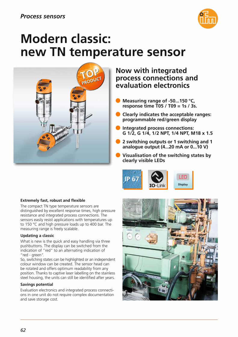
62
Now with integrated process connections and evaluation electronics
Extremely fast, robust and flexibleThe compact TN type temperature sensors are distinguished by excellent response times, high pressureresistance and integrated process connections. The sensors easily resist applications with temperatures upto 150 °C and high pressure loads up to 400 bar. Themeasuring range is freely scalable.
Updating a classicWhat is new is the quick and easy handling via threepushbuttons. The display can be switched from the indication of ”red“ to an alternating indication of “red - green“. So, switching states can be highlighted or an independent colour window can be created. The sensor head can be rotated and offers optimum readability from any position. Thanks to captive laser labelling on the stainless steel housing, the units can still be identified after years.
Savings potentialEvaluation electronics and integrated process connecti-ons in one unit do not require complex documentationand save storage cost.
Measuring range of -50...150 °C, response time T05 / T09 = 1s / 3s.
Clearly indicates the acceptable ranges: programmable red/green display
Integrated process connections: G 1/2, G 1/4, 1/2 NPT, 1/4 NPT, M18 x 1.5
2 switching outputs or 1 switching and 1analogue output (4...20 mA or 0...10 V)
Visualisation of the switching states byclearly visible LEDs
Modern classic: new TN temperature sensor
Process sensors
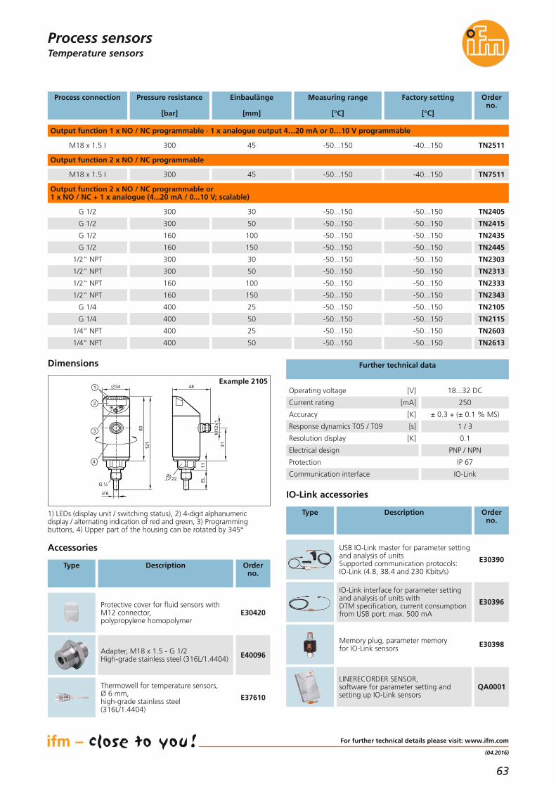
63
(04.2016)
Temperature sensors
For further technical details please visit: www.ifm.com
Process sensors
Adapter, M18 x 1.5 - G 1/2High-grade stainless steel (316L/1.4404) E40096
Protective cover for fluid sensors with M12 connector,polypropylene homopolymer
E30420
Accessories
Type Description Orderno.
Accuracy [K] ± 0.3 + (± 0.1 % MS)
Electrical design PNP / NPN
Protection IP 67
Communication interface IO-Link
Resolution display [K] 0.1
Operating voltage [V] 18...32 DC
Current rating [mA] 250
Further technical data
IO-Link interface for parameter settingand analysis of units with DTM specification, current consumptionfrom USB port: max. 500 mA
E30396
Memory plug, parameter memoryfor IO-Link sensors E30398
LINERECORDER SENSOR,software for parameter setting and setting up IO-Link sensors
QA0001
IO-Link accessories
Type Description Orderno.
USB IO-Link master for parameter settingand analysis of unitsSupported communication protocols: IO-Link (4.8, 38.4 and 230 Kbits/s)
E30390
1) LEDs (display unit / switching status), 2) 4-digit alphanumeric display / alternating indication of red and green, 3) Programming buttons, 4) Upper part of the housing can be rotated by 345°
Einbaulänge
[mm]
Pressure resistance
[bar]
300 45
Measuring range
[°C]
Factory setting
[°C]
Orderno.
Output function 1 x NO / NC programmable · 1 x analogue output 4…20 mA or 0…10 V programmable
-50...150 -40...150
Process connection
M18 x 1.5 I TN2511
300 45
Output function 2 x NO / NC programmable
-50...150 -40...150M18 x 1.5 I TN7511
300 30 -50...150G 1/2 TN2405
300 50 -50...150G 1/2 TN2415
160 100 -50...150G 1/2 TN2435
160 150 -50...150G 1/2 TN2445
300 30 -50...1501/2" NPT TN2303
300 50 -50...1501/2" NPT TN2313
160 100 -50...1501/2" NPT TN2333
160 150 -50...1501/2" NPT TN2343
400 25 -50...150G 1/4 TN2105
400 50 -50...150G 1/4 TN2115
400 25 -50...1501/4" NPT TN2603
400 50 -50...150
-50...150
-50...150
-50...150
-50...150
-50...150
-50...150
-50...150
-50...150
-50...150
-50...150
-50...150
-50...1501/4" NPT TN2613
Output function 2 x NO / NC programmable or 1 x NO / NC + 1 x analogue (4...20 mA / 0...10 V; scalable)
Response dynamics T05 / T09 [s] 1 / 3
Thermowell for temperature sensors,Ø 6 mm,high-grade stainless steel (316L/1.4404)
E37610
Dimensions
48
M12
x1
22 EL
11
41
34
8012
1
4
3
2
1
G ¼
6
Example 2105

64
Process sensors
Temperature sensors with DEUTSCH-, AMP or M12 connector
Miniaturisation for mobile applicationsThe DEUTSCH, AMP or M12 connectors of the newTA/TU/TM temperature sensors allow fast and easy installation in mobile machines. Their extremely compact housing ensures that the sensors are particularly suited for use in applicationswhere space is limited.
Areas of applicationThe sensors of type TA/TU/TM are suited for mobile applications and especially for hydraulic and pneumaticapplications with high operating pressure. The high vibration and shock resistance, the high protection rating, the excellent EMC resistance and theE1 conformity make the TA/TU/TM sensors particularlysuitable for use in mobile machines.
Compact design with G 1/4 process connection
Fast response time T05 / T09 = 1 s / 3 s
Installation depths of 25...200 mm
Measuring range -50...150 °C
Robust due to welded stainless steel housing
Temperature sensors for mobile machines

65
(04.2016)
Process sensors
For further technical details please visit: www.ifm.com
Temperature sensors
Installation length
[mm]
Order no.
Factory setting
Connector
G 1/4 process connectionAnalogue output 4...20 mA
25 M12
50 M12
200 M12
25 DEUTSCH
G 1/4 process connectionAnalogue output 0.5...4.5 V
25 M12
25 DEUTSCH
25 AMP
Operating voltage [V DC]Type TA 10...30
Operating voltage [V DC]Type TU 8...32
Protection rating IP 68, IP 69K / lll
Materials in contact with the medium
High-grade stainless steel(316L/1.4404)
Further technical data
Reverse polarity / overload protection • / •
Response dynamics T05 / T09 1 s / 3 s
Ambient temperature [°C] -40...100
EMC DIN EN 61000-6-2DIN EN 61000-6-3
Dimensions
TA3105
TA3115
TA3155
TA4105
50 DEUTSCH TA4115
25 AMP TA5105
50 AMP TA5115
TU3105
TU4105
TU5105
-50...150 °C
-50...150 °C
G 1/4 process connectionPt1000, class A
25 M12
25 DEUTSCH
TM5101
TM6101
-40...150 °C
1/4" NPT process connectionAnalogue output 4...20 mA
50 M12
50 M12
TA3313
TA3317
0...300 °F / 0...100 °C
Wiring
M12
x118
,8
6
55,3 13EL
19 G ¼
TA3121
,8
6
25,4
EL1359,6
19 G ¼
TA41
25,8
6
EL1359,8
19 G ¼
21,8
TA51
L+BN1
WH2 OUT
BN1
WH2
BU3
L+
L
OUT
TU31TA31
A
C
BOUT
L -
L +L +TU41
1
3 L +
OUT 1
2
3OUT
L +
L -TU51TA51
A
B OUT
+L
TA41

66
Repeater to extend AS-i networks up to 1000 m
OperationRepeaters are used for AS-Interface to enable the network cable run to be extended beyond 100 m. Galvanic separation of network segments and in-dependent voltage supplies ensure stability. The 62 participants are provided with a higher total currentand the voltage drop decreases.
Features of the unitThe improved performance is packed into the newSmartLine housing. While conventional repeaters usually have a temperature range from 0...55 °C, the new unit from ifm operates reliably across a broadrange from -25...70 °C. The improved operating temperature range makes thenew unit from ifm a class leader. This results in a longerlife time thus saving time and money.
Increased operating temperature range -25...70 °C
Reliable long term performance in tough conditions
Fast data transfer for Safety at Work
Clearly visible diagnostic LEDs
Plug-in connection terminals
New AS-i repeater for extended networks
Industrial communication

67
(04.2016)
Products
Protection IP 20, Combicon connectors AC3225
Total current consumption [mA]via AS-i 2 x 60
Ambient temperature [°C] -25...70
Housing material PA 6.6
SmartLine AS-i repeaterAC3225
AS-Interface cable extensionsIndustrial communication
Technical data
SmartLine AS-i repeater
For further technical details please visit: www.ifm.com
Orderno.
Type Description
Dimensions
10825,493 12
5,7
1
LED
2
3
35,5
1) plug with cage clamp connection2) panel for labelling3) Din rail adapter
Operating voltage [V DC] 26.5...31.6
AS-i power supply 115/230 V AC,output current (AS-i) 2.8 A AC1256
AS-i power supply 115/230 V AC,output current (AS-i) 8 A AC1258
Accessories
Orderno.
Type Description

68
Safe automation system includes PLC and gatewayfunctions
All-in-one: more than just a PLCJust as a smartphone is more than just a phone, thenew SmartPLC is more than just a simple PLC. It has the flexibility for different tasks, even in safety-related applications up to SIL 3, PL e. For example as:– fail-safe PLC– standard PLC– AS-i gateway– visualisation system– protocol converter– data logger– intelligent evaluation unit (ifm system solutions)Two integrated PLCs (1 x fail-safe, 1 x standard),powerful processors, a large memory and a multitude of supported protocols allow the control of sophisticatedsystems – and this at an unbeatable price!
Quick and easy set-up
Flexible and future-proof thanks to connective hardware and CODESYS V3
High machine uptime due to sophisticateddiagnostics
Unbeatable price/performance ratio
Safe up to SIL 3, PL e
Safety 4.0: the safe SmartPLC
Industrial communication

69
(11.2015)
Products
Orderno.
AS-i Profinet gateway with safe preprocessing AC402S
AS-i EtherNet / IP gateway with safe preprocessing AC422S
Dimensions
106,293
135,
512
8,2
AS-Interface Safety at WorkIndustrial communication
Type Description
AS-i gateway
For further technical details please visit: www.ifm.com
Accessories
Orderno.
AS-i data decoupling module AC1250
Type Description
Safe PLCCertified up to SIL3, PL e. Eight safe local inputs andfour safe local outputs. Convenient diagnostic functions, e.g. status indication for safe I/Os and error memorywith time stamp for up to 2,000 messages. Programming is done via CODESYS V3. Simplified replacement of slaves using automatic teach function.
Standard PLCThe PLC can be freely programmed using CODESYS V3.Its software and hardware operates independently ofthe fail-safe PLC, but it can of course communicatewith it and exchange data. The PLC has access to all interfaces of the system.
AS-i gatewayWithout programming, the SmartPLC can be used directly as a gateway for AS-i on the one side, and Profinet or EtherNet/IP on the other side. The integrateddisplay and the convenient web interface display all theavailable status information for the user and supportdiagnostics in case of a fault.
Data loggerOperational system data can be recorded via AS-i,EtherCAT, Modbus TCP, Profinet, EtherNet /IP, TCP/IP,UDP/IP and stored on the SD card or in the internalflash memory. If needed, the integrated real-time clock provides atime stamp for each recorded data block. This simplifiesthe documentation and diagnostics of processes.
Visualisation systemA freely programmable web visualisation based onHTML5 provides maximum transparency. An internetbrowser with HTML5 capability is sufficient on the finalunit (PC, tablet, smartphone). No further software is required. Even the full graphic display of the SmartPLCis freely programmable for visualisation tasks.
Platform ifm system solutionsWith the new ifm system solution apps, the processdata of different sensors is transmitted to commonfieldbus systems and their parameters are easily madeaccessible. These tailored apps can be loaded onto theSmartPLC without programming software. This makesyour installation fit for Industry 4.0.
Protocol converterConnect your sensors and Ethernet based devices toyour fieldbus: the SmartPLC can be used as protocolconverter between Profinet, EtherNet /IP on the oneside and AS-i, EtherCAT, Modbus TCP, TCP/IP, UDP/IPand IO-Link on the other side.
All-in-oneThe new SmartPLC combines two separate PLCs in one compact housing. While the one PLC solves safety-related applications, the second PLC either works as astandard PLC or as platform for other tasks. Both PLCs communicate with each other, so that entireplant controls can be implemented including safetyfunctions and visualisations with only one SmartPLC.

70
Safe bus connection for light guards
Safe AS-i input module especially for light guard applications
Module for light gridsUsing this new, safe input module, light guards andother safety-related sensors with electronic OSSD out-puts can be connected to AS-i Safety at Work.
Control muting lampThe integrated outputs ensure the connection of twosignal lamps.
Quick mounting without toolsThe tried-and-tested quick mounting avoids wiringfaults. There is one M12 connecting socket each for thetransmitter, the receiver and the two signal outputs.
Two alternatives for the voltage supplyDepending on the design, the light guard and the signal lamps can be completely supplied via AS-i or anexternal auxiliary voltage.
Optimised M12 socket connection for light guard applications
Muting lamp can be controlled by PLC
Precise and flexible quick mounting
Supply of the light guards from AS-i
High safety due to certification to EN 62061/SIL3 and EN ISO 13849-1/ PL e
With signal effect: AS-i modulefor OSSD inputs
Industrial communication

71
(11.2015)
The products
Orderno.
Advantages and customer’s benefitsFail-safe sensors with a current consumption below 200 mA can be operated on AC507S without auxiliaryvoltage. Connection is only made via the yellow AS-iflat cable.
AS-i quick connectionThe quick-connection technology provides a high degree of installation reliability and flexibility. The AS-i flat cable can be connected from three different directions.
Diagnosis on siteThe LEDs indicate the status of the inputs and outputsand the communication.
SafetyThe module meets the requirements up to SIL3 according to EN 62061 and PL e to EN 13849-1. In the event of afault, the integrated communication monitoring switches the signal outputs off.
ApplicationsThe module is designed for the connection of electro-sensitive protective equipment (ESPE) with electronicoutputs to EN 61496-1. It is particularly suited for theconnection of safe inductive sensors such as GM705S.Pulse pick-ups for the display of muting functions canbe connected via M12 sockets.
Operating voltage (AS-i) [V DC] 26.5...31.6
Short-circuit protection •
Overload protection •
AS-i profile S-7.B.E
AS-i specification 2.11 + 3.0
Extended addressing mode –
Ambient temperature [°C] -25...55
Protection IP 67
Safe AS-i input modulesAC507S, AC508S
Technical data
Type Description Order no.
Safe AS-i input module
Sensor supply Inputs / outputs: via AS-iCurrent rating inputs / outputs: 200 mA in totalTotal current consumption: ≤ 280 mA
AC507S
Sensor supply Inputs / outputs: 24 V external, PELVCurrent rating inputs / outputs: inputs 200 mA, outputs 500 mATotal current consumption: < 80 mA
AC508S
AS-Interface Safety at Work
For further technical details please visit: www.ifm.com
Dimensions
45
103
40,244,7
25,8
Industrial communication
Adapter cable,from 8 poles to 5 poles,M12 plug / M12 socket,configured for automatic operation
EY3090
Adapter cable,5 poles,M12 plug / M12 socket,configured for "short range"
EY3092
Adapter cable

72
Easy communication with thePLC and in parallel to the LINE-RECORDER SMARTOBSERVER*
Interface for factory networkingWith the integrated LINERECORDER AGENT, this masterenables direct networking of all connected IO-Link devices with a local server via an Ethernet network.Using this connection, machine data, process parameters and diagnostic data can be directly read and processedby the IT. The easy-to-use server software LINERECORDER SMARTOBVSERVER* enables data evaluation by meansof customer-specific cockpits. Using the same communication mechanisms, it is possible to directly couple machines and exchange production-related data.
From sensor to SAPFor the first time, sensor data can be directly transmitted to management software - and this on a factory-wideor even worldwide level. Evaluation of the obtained data in real time enables anincrease in production efficiency and energy savings inthe context of Industry 4.0.
The IO-Link master module for different applications:from machine condition monitoring to remote maintenance of wind parks.
*LINERECORDER SMARTOBSERVER is a server-based software for data storage, predictive maintenance and quality monitoring.
8 IO-Link ports V1.1 with COM1, COM2,COM3 and SIO support
10 extra binary inputs 24 V DC and 2 configurable binary inputs/outputs
2 Ethernet ports 10/100 Base-TX with integrated switch
Slim housing for control cabinet mounting
Extended temperature range of 0...70 °C
8-port IO-Link master module with LINERECORDER AGENT embedded
Industrial communication

73
(04.2015)
System solutionsIndustrial communication
For further technical details please visit: www.ifm.com
Special features
Ethernet interface for PLC connectionThis IO-Link master operates as an input/output cardwith a total of 20 I /Os, of which 8 are for IO-Link devices and the rest for binary signals.All signals can be easily transmitted to compatible controllers via the standard fieldbuses EtherNet /IP orProfinet.Two ways simultaneously = PLC and server in parallelSo far, all sensor signals had to be sent by the PLC to higher-level systems. This is now done via a parallelcommunication path (Y path). The PLC program remains unchanged.Integrated web server for configuration and diagnosticsNo special software is required for configuration. All IO-Link settings can be made via the integrated web interface. To do so, a standard PC with Ethernet connection and web browser is required.Convenient IODD integrationVia the web interface, up to 8 different IODDs (IO-Linkdevice descriptions) can be loaded into the master. After connection of the IO-Link devices, the correspondingIODDs are automatically assigned to the connected IO-Link devices and the corresponding ports.
Parallel sensor communication
IO-Link master IO-Link master
PLC
industrial fieldbus
LR agent communication (option)
LINERECORDERweb-baseduser interface
IO-Linksensors
· · ·1 2 7 8
server
IO-Link
IO-Linksensors
· · ·1 2 7 8
Technical data
“Y“ path for PLC data exchange and a parallel connection to the server via LINERECORDER AGENT
IO-Link master module for connection to fieldbuses
Fieldbus connection EtherNet/IP Profinet
Further protocols Modbus / TCP (slave)
Order no. AY1020 AY1000
Supply voltage [V] 18...30 DC
Current consumption [A] 2 (24 V)
IO-Link version 1.1
Number of IO-Link ports 8
Parameter memory •
IO-Link port A / port B up to 8, configurable
Inputs/outputs IO-Link / SIO configurable
IO-Link baud rates COM 1...3 4.8k, 38.4k, 230.4kBaud
Digital inputs max. DI 8 (16) +2
Digital outputs max. DO 8 + 2
IO-Link / DI / DO status LEDs 20
Ethernet connections 2x (10/100 BASE-Tx)
Module / Ethernet status LEDs 7
Ethernet sockets RJ45
Electrical connections screw terminals
Protection IP 20
Housing material polyamide plastics
Ambient temperature [°C] 0...70
Installation DIN rail

74
Short overview of the most important ideas and advantages of IO-Link
IO-Link = universal process data interfaceIO-Link masters are universal input/output modules.Different types of units can be operated on the sameport: IO-Link sensors, IO-Link actuators and units withswitching signal. Therefore, one IO-Link port can replace several components: analogue (4...20 mA, 0...10 V) and binary input and output cards.
IO-Link = smart sensor interfaceIn smart sensors, IO-Link is already integrated. So, datacan be exchanged bidirectionally with the controller,e.g. diagnostics and maintenance messages or data forremote parameter setting.
IO-Link = easy set-upThe easiest way to obtain sensor process values is aseasy as the connection to an analogue card. Connectthe sensor to the IO-Link master – done.Replacement is just as easy. All sensor parameters arestored in the master and transferred to the new unit.
Smart IO-Link sensors can be conveniently set using theLINERECORDER SENSOR 4.0 software.The sensor settings can be stored, copied, loaded orcloned to other units.
The USB IO-Link interface establishes the connectionbetween IO-Link units and the LINERECORDER SENSOR.It is compatible with most Windows PCs.
IO-Link masters are available for all majorPLCs and fieldbuses
Simple configuration via LINERECORDERSENSOR (PC) or via web interface
IO-Link app for AS-i gateways withautomatic network scan of all sensors
A wide range of ifm sensors with IO-Link:encoders, capacitive, photoelectric, temperature, flow, pressure and level sensors
IO-Link – the standard interfacefor smart sensors
Industrial communication

75
(04.2015)
System solutionsIndustrial communication
For further technical details please visit: www.ifm.com/gb/io-link
10 good reasons to use IO-Link
Fast and easy set-up and service:1. Offline parameter setting of the sensors prior to
installation.2. Automatic sensor detection online when using the
IO-Link app on the AS-i/fieldbus gateway.3. Easy sensor replacement with automatic parameter
setting by the master.Sensor identification included.
High machine uptime:4. Avoidance of incorrect handling during operation
by deactivating the operating keys on the sensor.5. Easy transmission of the measured values without
conversion losses; values on the sensor displaycorrespond to the values on the machine display.
6. Highly interference immune - because digital -analogue value transmission in comparison withconventional analogue technology. And this usingan unscreened cable without special grounding.
7. Machine diagnostics up to the sensor levelfunctions without disrupting the operation.
Less wiring saves installation costs:8. Several analogue signals and switch points can be
transmitted using only one standard 3-wire cable.This reduces the number of terminals and makesspace in the cable duct.
9. Sensors and actuators, analogue or binary, can beconnected via IO-Link ports. This replaces differentinput/output modules.
Investment security:10. IO-Link has been internationally standardised to
IEC 61131-9 and is therefore future-proof. Theacceptance of all leading automation suppliersensures investment security for OEMs and users.
IO-Link is the interface to Industry 4.0.
Typical plant configuration
IO-Link masterIP20
IO-Link masterIP67
sensor parameter settingPLC
industrial fieldbus
LINERECORDERsensor 4.0
MODBUS-TCP
IO-Linksensors
· · ·1 2 7 8
IO-LinksensorwithIO-Link
IO-Link
IO-Linksensors
· · ·1 2 7 8
USBadapter
Order data
Technical data
IO-Link service & maintenance tools
Characteristic IO-Link data
IO-Link USB master low power E30396
IO-Link USB master ext. power E30390
LR Sensor 4.0 parameter setting softwarewith IODD import QA0001
Analogue converter -50...300 °CPt100/Pt1000 to IO-Link TP3232
Analogue converter 0...100 °CPt100/Pt1000 to IO-Link TP3237
IO-Link app for AS-i gateways AC14xx AP3002
Analogue converter -50...150 °CPt100/Pt1000 to IO-Link TP3231
Memory plug - sensor-parameter memory E30398
Cable length [m] 20
Line physics type A 3-wire cable,unscreened
Connection M12, M8, M5, terminals
Process data (PD) per device 1 bit ... 32 bytes
Cycle time for 2 bytes [ms] 2.3
Parameters, diagnostics and events acyclic transmission
Power supply type APower supply type B
sensors 200 mAsensors + actuators
separated
M12 pin connection type A
pin 1: 24 V DCpin 3: 0 V DCpin 4: IO-Link /
binary input / output
Description Orderno.

76
Easy as using a smartphone!Individual connection to a PLCby means of reloadable apps
Until now: complex programmingModern sensors offer more and more intelligent functions that can also be made available to the PLC via interfaces like IO-Link or TCP/IP.To use them, the PLC programmer has to individuallyimplement the functionalities in the PLC. This is verytime-consuming and costly, especially when it comes to implementing the required user interfaces.
From now on: fit for Industry 4.0 – ifm System SolutionsWith the new ifm System Solution Apps ifm electronichas developed a system which is easy to create. It allows process data from different sensors to be transmitted tocommon fieldbus systems, and their parameters are easily accessible. For this purpose, ifm now offers tailored apps whichcan be loaded into the ifm fieldbus gateway withoutany programming software.
Fast and easy integration of intelligentsensors into the PLC world
No special PC software required, an internet browser is sufficient
PLC connection via the fieldbus protocolsProfinet, Profibus, EtherNet/IP and others
Smart additional functions tailored to thesensors selected
Straightforward web configuration instead of time-consuming and costly programming
Industry 4.0 made easy – Apps instead of expensive programming
Industrial communication

77
(11.2015)
The products
Orderno.
System solutionsIndustrial communication
ifm System Solution Apps
For further technical details please visit: www.ifm.com
ifm System Solution AppsThe centrepiece for using the ifm System Solution Appis the AC14 SmartPLC. On the one hand, the devicehas a certified fieldbus interface (Profinet, Profibus, EtherNet/IP) for the connection to a PLC. On the other hand, the AC14 features excellent communication possibilities via an additional EtherNetinterface and up to two AS-i masters for connection toa variety of sensors and actuators.Loading and configuration of the app is made via theintegrated web interface, i.e. all necessary settings canbe carried out conveniently via a device with an inter-net browser.
System overview
Example: ifm System Solutions App for O3D camera
Web-based configuration
PLCworld
Sensorworld
www.ifm.comSystem Solution Apps
AC14
analogue signalsbinary signals
Ethernet
TCP/IPUDP/IP
Web-based configuration
AC14 with App for O3D camera
PLCworld
Sensorworld
PLC TCP/IP
O3D camera
IO-Link scanner and configurator AP3002
Field bus connection of up to five type O2I multi-code readers to Profibus, Profinet, EtherNet/IP AP3022
Field bus connection of up to three type O3D200 multi-code readers to Profibus, Profinet, EtherNet/IP AP3032
AS-i based DTA ID systems: user-friendly writing of RFID tags, history data AP3042
Data collector: up to 30 process data can be freelynamed and scaled, history data with time stamp can be stored on SD card, fieldbus connection to Profibus,Profinet and EtherNet/IP
AP3052
Tool changeover: via the fieldbus (Profibus, Profinet, EtherNet/IP) free selection of predefined AS-i configurations
AP3062

78
Identification systems
RFID evaluation system DTEnow with EtherCAT
Always know what's going onifm RFID systems are optimised for quality assuranceand production control, e.g. for identifying tools or monitoring production steps.What used to be written in the documents accompany-ing the goods is now stored on electronic transponders.Advantage: the information cannot get lost and is available at any time and anywhere.
New: DTE103 evaluation unit with EtherCATEtherCAT is the fastest Ethernet technology with exceptional performance. The free network topologyflexibly adapts to the plant structure. Switches andhubs are not required. This saves costs.The devices can be exchanged during operation. This ensures a high plant uptime. The automatic address allocation simplifies set-up and device replacement.Specialist IT knowledge is not required.
RFID DTE103 with web server for device setup, diagnosis and monitoring
Robust RFID antennas in different designs
Increased range through optional antenna adapters
Connection of RFID antennas, sensors oractuators
Simple connection of the antennas viastandard cables up to 20 m
The fastest and most flexibleRFID ever
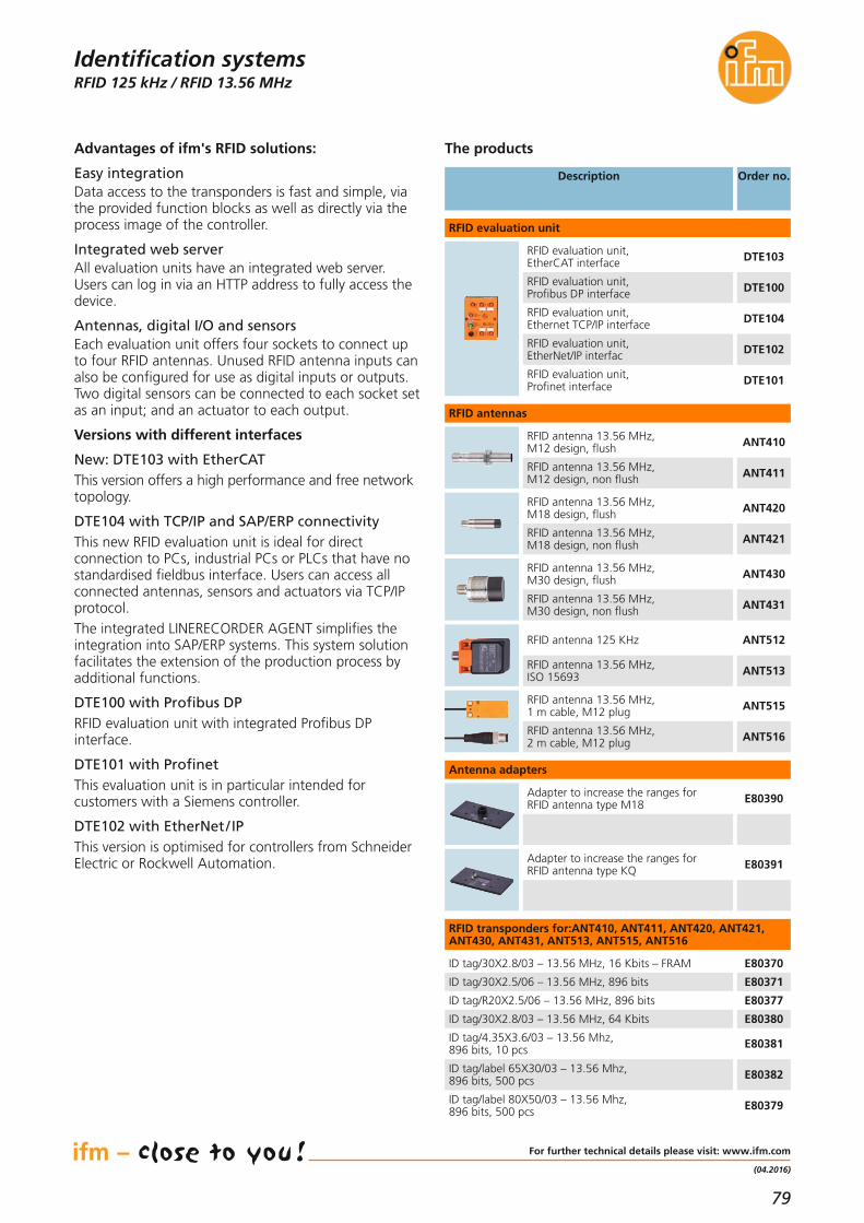
79
(04.2016)
RFID 125 kHz / RFID 13.56 MHz
For further technical details please visit: www.ifm.com
Identification systems
Description Order no.
ANT512RFID antenna 125 KHz
ANT513RFID antenna 13.56 MHz,ISO 15693
E80370ID tag/30X2.8/03 – 13.56 MHz, 16 Kbits – FRAM
E80371ID tag/30X2.5/06 – 13.56 MHz, 896 bits
E80377ID tag/R20X2.5/06 – 13.56 MHz, 896 bits
RFID evaluation unit
RFID antennas
The products
ANT515RFID antenna 13.56 MHz,1 m cable, M12 plug
ANT516RFID antenna 13.56 MHz,2 m cable, M12 plug
ANT410RFID antenna 13.56 MHz,M12 design, flush
ANT411RFID antenna 13.56 MHz,M12 design, non flush
ANT430RFID antenna 13.56 MHz,M30 design, flush
ANT431RFID antenna 13.56 MHz,M30 design, non flush
ANT420RFID antenna 13.56 MHz,M18 design, flush
ANT421RFID antenna 13.56 MHz,M18 design, non flush
E80380ID tag/30X2.8/03 – 13.56 MHz, 64 Kbits
E80381ID tag/4.35X3.6/03 – 13.56 Mhz, 896 bits, 10 pcs
E80382ID tag/label 65X30/03 – 13.56 Mhz, 896 bits, 500 pcs
E80379ID tag/label 80X50/03 – 13.56 Mhz, 896 bits, 500 pcs
RFID transponders for:ANT410, ANT411, ANT420, ANT421,ANT430, ANT431, ANT513, ANT515, ANT516
Antenna adapters
E80390Adapter to increase the ranges for RFID antenna type M18
E80391Adapter to increase the ranges for RFID antenna type KQ
Advantages of ifm's RFID solutions:
Easy integrationData access to the transponders is fast and simple, viathe provided function blocks as well as directly via theprocess image of the controller.
Integrated web serverAll evaluation units have an integrated web server.Users can log in via an HTTP address to fully access thedevice.
Antennas, digital I/O and sensorsEach evaluation unit offers four sockets to connect upto four RFID antennas. Unused RFID antenna inputs canalso be configured for use as digital inputs or outputs.Two digital sensors can be connected to each socket setas an input; and an actuator to each output.
Versions with different interfaces
New: DTE103 with EtherCATThis version offers a high performance and free network topology.
DTE104 with TCP/IP and SAP/ERP connectivityThis new RFID evaluation unit is ideal for direct connection to PCs, industrial PCs or PLCs that have nostandardised fieldbus interface. Users can access allconnected antennas, sensors and actuators via TCP/IPprotocol.The integrated LINERECORDER AGENT simplifies the integration into SAP/ERP systems. This system solutionfacilitates the extension of the production process byadditional functions.
DTE100 with Profibus DPRFID evaluation unit with integrated Profibus DP interface.
DTE101 with ProfinetThis evaluation unit is in particular intended for customers with a Siemens controller.
DTE102 with EtherNet/ IPThis version is optimised for controllers from SchneiderElectric or Rockwell Automation.
RFID evaluation unit, EtherNet/IP interfac
RFID evaluation unit, Ethernet TCP/IP interface
RFID evaluation unit, Profinet interface
RFID evaluation unit, Profibus DP interface
DTE102
DTE104
DTE101
DTE103RFID evaluation unit, EtherCAT interface
DTE100

80
More flexibility in conveying due to extendedoperating distances
Reliable identificationThe new robust RFID antennas have been developedespecially for the requirements in automation and conveying technology. In combination with the antennaadapters, they ensure excellent operating distances formore reading reliability even under adverse installationconditions.The industrially compatible connection technology"ecolink" ensures quick and reliable connection of antennas and sensors to the RFID evaluation units.
Ready for Industry 4.0The ifm RFID evaluation units offer a wide range of industrial fieldbus interfaces. RFID-based identificationtasks can easily be integrated into SAP/ERP systems.
Longer ranges with antenna adapters for which a patent has been applied
Antenna adapters for cylindrical M18 and rectangular KQ housings
Robust RFID antennas M18 for flush andnon flush installation
Extra flat antenna in rectangular KQ design for limited space conditions
Easy integration into SAP/ERP systems by means of evaluation units
Adapters to increase the rangesof the new RFID antennas
Identification systems

81
(11.2015)
RFID 125 kHz / RFID 13.56 MHz
Different interfaces
New: DTE104 with TCP/IP and SAP / ERP connectivityThis new RFID evaluation unit is ideal for direct connection to PCs, industrial PCs or PLCs that have nostandardised fieldbus interface. Users can access allconnected antennas, sensors and actuators via TCP/IPprotocol.
DTE100 system with Profibus DPRFID evaluation unit with integrated Profibus DP inter-face.
DTE101 with ProfinetThis evaluation unit is in particular intended for customers with a Siemens controller.
DTE102 system with EtherNet/IPThis version is optimised for controllers from SchneiderElectric or Rockwell Automation.
Easy integrationData access to the transponders is fast and simple, viathe provided function blocks as well as directly via theprocess image of the controller.
Integrated web serverAll evaluation units have an integrated web server.Users can log in via an HTTP address to fully access thedevice.
Antennas, digital I/O and sensorsEach evaluation unit offers four sockets to connect upto four RFID antennas. Optionally, unused RFID antennainputs can also be used for the control of outputs orthe detection of digital input signals. Two digital sensors can be connected to each socket set as an input; andan actuator to each output.
Customer benefitsThe integrated LINERECORDER AGENT simplifies the integration into SAP/ERP systems. This system solutionfacilitates the extension of the production process byadditional functions.With this version of the DTE104 the user is providedwith the ASCII protocol.
Application examplesTraceability of products plays an essential role in industry. By integrating LINERECORDER AGENT and SAP Connector the LR functions "Product Trace" and "Order Manage-ment" can be used.With RFID, materials and products can be unambiguously assigned within the production process. Here, the functions "Product Trace", "Order Manage-ment" and "Material Manager" are used.
For further technical details please visit: www.ifm.com
Identification systems
Description Order no.
RFID evaluation unit, EtherNet/IP interfac
RFID evaluation unit, Ethernet TCP/IP interface
RFID evaluation unit, Profinet interface
ANT512RFID antenna 125 KHz
ANT513RFID antenna 13.56 MHz,ISO 15693
E80370ID tag/30X2.8/03 – 13.56 MHz, 16 Kbits – FRAM
E80371ID tag/30X2.5/06 – 13.56 MHz, 896 bits
E80377ID tag/R20X2.5/06 – 13.56 MHz, 896 bits
RFID antennas
The products
RFID evaluation unit, Profibus DP interface
ANT515RFID antenna 13.56 MHz,1 m cable, M12 plug
ANT516RFID antenna 13.56 MHz,2 m cable, M12 plug
ANT410RFID antenna 13.56 MHz,M12 design, flush
ANT411RFID antenna 13.56 MHz,M12 design, non flush
ANT430RFID antenna 13.56 MHz,M30 design, flush
ANT431RFID antenna 13.56 MHz,M30 design, non flush
ANT420RFID antenna 13.56 MHz,M18 design, flush
ANT421RFID antenna 13.56 MHz,M18 design, non flush
E80380ID tag/30X2.8/03 – 13.56 MHz, 64 Kbits
E80381ID tag/4.35X3.6/03 – 13.56 Mhz, 896 bits, 10 pcs
E80382ID tag/label 65X30/03 – 13.56 Mhz, 896 bits, 500 pcs
E80379ID tag/label 80X50/03 – 13.56 Mhz, 896 bits, 500 pcs
RFID transponders for: ANT410, ANT411, ANT420, ANT421,ANT430, ANT431, ANT513, ANT515, ANT516
Antenna adapters
E80390Adapter to increase the ranges for RFID antenna type M18
E80391Adapter to increase the ranges for RFID antenna type KQ
DTE102
DTE104
DTE101
RFID evaluation unit
DTE103RFID evaluation unit, EtherCAT interface
DTE100
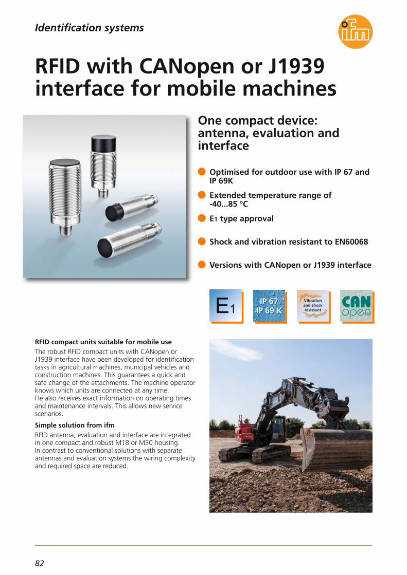
82
Optimised for outdoor use with IP 67 andIP 69K
Extended temperature range of -40...85 °C
E1 type approval
Shock and vibration resistant to EN60068
Versions with CANopen or J1939 interface
Identification systems
One compact device: antenna, evaluation and interface
RFID compact units suitable for mobile useThe robust RFID compact units with CANopen or J1939 interface have been developed for identificationtasks in agricultural machines, municipal vehicles andconstruction machines. This guarantees a quick andsafe change of the attachments. The machine operatorknows which units are connected at any time. He also receives exact information on operating timesand maintenance intervals. This allows new service scenarios.
Simple solution from ifmRFID antenna, evaluation and interface are integratedin one compact and robust M18 or M30 housing. In contrast to conventional solutions with separate antennas and evaluation systems the wiring complexityand required space are reduced.
RFID with CANopen or J1939 interface for mobile machines

83
(04.2016)
RFID 13.56 MHz
For further technical details please visit: www.ifm.com
Identification systems
Description Orderno.
E80370ID tag/30X2.8/03 – 13.56 MHz, 16 Kbits – FRAM
E80371ID tag/30X2.5/06 – 13.56 MHz, 896 bits
E80377ID tag/R20X2.5/06 – 13.56 MHz, 896 bits
The products
E80380ID tag/30X2.8/03 – 13.56 MHz, 64 Kbits
E80381ID tag/4.35X3.6/03 – 13.56 MHz, 896 bits, 10 pcs
E80382ID tag/label 65X30/03 – 13.56 MHz, 896 bits, 500 pcs
E80379ID tag/label 80X50/03 – 13.56 MHz, 896 bits, 500 pcs
Further technical data
Operating voltage [V DC] 9...32
Current consumption sensor [mA] < 50 at 24 V,< 85 at 12 V
Ambient temperature [°C] -40...85
Protection rating, protection class
IP 67 / IP 69K, III
Housing material stainless steel
Interfaces 1 x CAN
Supported CAN protocols CANopen, SAE J1939
Standards and tests(extract)
CE, radio approval
Connection M12 connector
Jumper, M12,5 m, black, PUR cable, LED EVC039
Jumper, M12,5 m, black, PUR cable EVC069
Socket, M12,2 m black, PUR cable EVM036
Socket, M12,10 m black, PUR cable EVM038
Socket, M12,5 m black, PUR cable EVC492
RFID transponders
Accessories
BasicDisplay XL, 4,3",CAN Interface CR0452
Display
Connection technology
Type Description Order no.
Type Description Order no.
Process and dialogue unit PDM360 NG,7" colour display CR1081
DTM424M18 flush, 13.56 MHz
DTM425M18 non flush, 13.56 MHz
DTM434M30 flush, 13.56 MHz
DTM435M30 non flush, 13.56 MHz
RFID evaluation unit / RFID antennaCANopen interface
DTM426
DTM427
DTM436
DTM437
RFID evaluation unit / RFID antennaSAE J1939 interface
M18 flush, 13.56 MHz
M18 non flush, 13.56 MHz
M30 flush, 13.56 MHz
M30 non flush, 13.56 MHz
ApplicationMobile machines are becoming ever more complex and complicated to use. Individual components assumemore and more tasks.With ifm's RFID system handling can be simplified and errors can be avoided: individual components orattachments are identified by means of an RFID tag andthe corresponding set-up is set automatically in thecontroller.Set-up times are minimised. Automatic identificationsimplifies the creation of user-specific system set-ups.Wrongly set process parameters are a matter of thepast.
Higher productivityInformation on maintenance intervals and operatingtimes can automatically be generated and stored sincethe controller detects when and how long a specificmachine set-up runs. This increases productivity.
Perfectly suited for use in industrial applicationsThe RFID system is also suitable for industrial applications in which CANopen controllers are used. In this environment the DTM4xx RFID identification system is ideal thanks to its excellent price / performance ratio.

84
Offers more than ISO monitoring
Compact vibration sensorFor small and medium-sized machines (such as motors,fans, pumps and compressors) whose vibration is oftenmonitored manually or not at all, ifm electronic nowhas a simple and interesting alternative.The latest member of the compact design VN, VNB211,monitors online the overall vibration status of machinery and plant according to ISO 10816 and the resulting acceleration (delivery status). In addition a process value(e.g. temperature) or another switching signal (VNA001) can be monitored via the analogue input. The historymemory integrated in the device permits logging of thedata for subsequent trend display in the PC softwareVES004.Parameters such as limits can be configured via thepushbuttons. Changes of the delivery status (basic parameter setting) are also made via the PC software.
VNA001 for vibration monitoring of an external measurement point, alternatively4...20 mA current signal, e.g. temperature
Two vibration values e.g. velocity and acceleration or shock and bearing noise
Freely adjustable frequency bands e.g. formonitoring according to ISO 10816
Integrated display with colour change inthe event of infractions of the limits
Compact vibration monitoring oftwo measurement points
Condition monitoring systems

85
(11.2015)
Vibration monitoring systems
DimensionsM
12x1
5162,4
14
65,3
36
20 M5
37,6
5
10
4
5,3
M8x
1
Accessories
Type Description Orderno.
USB / M8 cable E30136
Adapter UNF / M5(pack quantity 10 pieces) E30137
Power supply E30080
Wiring diagram
43
21
4
2 1
35
Pin 1: 5 V via USB interfacePin 2: USB_D-Pin 3: L-Pin 4: USB_D+
Pin 1: L+ (9.6...30 V DC)Pin 2: Out 1 switching output or
current output 0/4...20/22 mA (configurable)Pin 3: L-Pin 4: Out 2 switching outputPin 5: In 0/4...20 mA
For further technical data please go to: www.ifm.com
Condition monitoring systems
Vibration sensor VN• Process connection via M12 x 1 and
M8 x 1 connectors• Parameter setting via PC software VES004• Configuration via sensor pushbuttons
Connection technology
Type Description Orderno.
Socket, M12, 2 m black, PUR cable, screened EVC535
Socket, M12, 2 m black, PUR cable, screened EVC532
Technical data
Operating voltage [V]9.6...30 DC or using USB
(switching outputs not active)
Protection IP 67
Ambient temperature [°C] -30...60
Selftest •
Vibration sensorVNB211
Data interface USB; 2.0
History memoryRing memory,
686774 data records, with real-time clock
Outputs
2 switching outputs or1 switching output and
1 analogue output 4...20 mA (can be set using the sensor pushbuttons)
Input [mA] 1 analogue input 0/4...20
Display 4-digitalphanumeric display
Measuring range [g] 0...25
Measurementmethod Vibration acceleration / vibration velocity
Y connection cable,M12 plug / 2 x M12 socket E12405
Acceleration sensor, M12 connector,Housing materials: high-grade stainless steel (316L/1.4404), Protection: IP 68 / IP 69K
VNA001
Parameter software VES004

86
Modular mini controller withhigh-current relay outputs
ecomatmobile BasicIn many small and compact mobile applications, the requirements on control tasks are increasing. Cost-optimised, modular mini controllers for mobile useare in demand. ifm offers ecomatmobile Basic consisting of the com-ponents BasicRelay, BasicController and BasicDisplaythat are adapted to each other. This BasicController family is now complemented by the BasicController relay. Its special feature is made up of six protected powerrelay outputs with diagnostic capability for the supplyof high-current consumers in mobile machines. In addition it has multifunctional digital and analogueinputs that can be configured via the application soft-ware. The BasicController relay is freely programmablevia the IEC61131-3-compatible CODESYS software.
High-performance, protected relay outputs with diagnostic function
Connection of sensors and actuators without further external wiring
Powerful CAN interfaces for various communication tasks
Easy installation due to adapted mechanical ecomatmobile Basic concept
Programmable to IEC 61131-3 with CODESYS
Power management in mobile vehicles
Systems for mobile machines

87
(11.2015)
Mobile controllers
Functions and advantagesThe compact, flexible and inexpensive mini controllerreplaces the conventional relay logic and also demanding and complex process controllers.
• Mechanical designThe control electronics integrated in a compact plastic housing provides all the necessary connectionsfor the inputs and outputs, communication and pro-gramming. The coded connectors for mobile use areeasy to handle and available all over the world. Theconnection of sensors and actuators is carried out without further external wiring. Due to an increase ofthe protection rating through a cover and a pluggable cable seal the BasicController can also be used in areas that are exposed to splashing water.
• Powerful electronicsThe integrated 32-bit processor and the electronicsare optimally tailored to the application. Inputs andoutputs can be configured to the application via theuser program. The powerful plug-in relay outputs ensure the connection of high-current consumers. All relay outputs are with diagnostic capability and individually protected. Each output has a freely pro-grammable status LED. Thanks to the additionalmulti-functional inputs a flexible control module formobile machines is available.
• Programmable to IEC 61131-3The CODESYS software enables a clear and easy creation of the application software for the user. The control module BasicController supports all common CODESYS programming languages. Simpleand clearly structured function libraries are availablefor communication and special device functions.
• Communication interfacesThe BasicController is equipped with two CAN inter-faces to ISO 11898. These interfaces are used to exchange data with the connected BasicDisplay, further BasicController modules or the engine controller. Among others, the interfaces support theCANopen protocol and the J1939 protocol. The CANinterfaces are also used for programming. To do so, the unit electronics is directly and con-veniently activated via the powerful PC-CAN interfaceCANfox. In this way, operating system and application program can be loaded or parameters changed.
Applications:compact construction machines, attachments, mini vehicles, special functions
Inputs (total):Digital, analogue, frequencyDigital, resistance measurement
844
Outputs (total):Micro relay ISO 7588-3, 15 A (total current max. 60 A)Diagnostics via NO and NC contact ofthe relay. Protected via mini controller to DIN ISO 8820-3
6
Data memory SRAM [kB] 592
Data memory Flash [kB] 1536
Data memory (retain), FRAM [kB] 1
For further technical details please visit: www.ifm.com
Systems for mobile machines
Description Orderno.
BasicController relay 8 I / 6 O relay CR0431
Technical data
BasicController relay
The products
Housing Plastic, potted
Device connection AMP blade male terminals 6.3 mm
Protection rating,with cover EC0401, EC0402
IP 20IP 54
Operating voltage [V DC] 8...32
Current consumption [mA] ≤ 45
Temperature rangeOperation [°C]Storage [°C]
-40...75-40...85
Indicators LED Red / green
Processor PowerPC, 50 MHz
Supported CAN protocols
CANopen(DS 301 V 4.1)
SAE J 1939free CAN protocol
Standards and tests(extract)
CE,E1 (UN-ECE R10)
Starter set consisting of BasicController 12 I / 8 O, BasicRelay, BasicDisplay incl. software, power supply,cable and accessories
EC0400
Module cover IP 54 without display recess, with cable seal EC0401
Plug set for BasicController relay EC0464
Mounting and contact set for BasicController relay EC0465
Relay and fuse set for 12 V applications EC0466
Relay and fuse set for 24 V applications EC0467
CAN programming interface CANfox EC2112
Adapter set CAN/RS232 for CANfox EC2113
CODESYS programming software, German CP9006
CODESYS programming software, English CP9008
Programming software CODESYS V 2.3

88
ecolink –a new dimension in connection technology.
ecolink M12 for demanding applicationsMost applications require special solutions. Only high-quality materials, safe production processes and fault-less mounting lead to success in the long run.The integrated end stop protects the O-ring againstdestruction caused by tightening the nut too much.Mounting and removal are carried out without tools.The asymmetrically acting vibration protection holdsthe nut tight in its position, guaranteeing an optimumand permanent seal.High-quality materials especially adapted to the applica-tion and intensive monitoring during and after produc-tion guarantee maximum quality standards.
Connection technology meets the M12standard (EN 61076)
Optimum sealing even when mountedwithout tools
The mechanical end stop protects the O-ring against destruction
Permanent vibration protection with saw tooth contour
LEDs clearly visible even under brightlighting
Connection technology
From factory automation tomachine tool industry
ecolink M12 – The secure connectioneven in difficult applications

89
(11.2015)
Applications:Factory automation, machine tool industry, construction of machinery, hydraulics
For further technical data please go to: www.ifm.com
SocketsConnection technology
Technical data:Operating voltage:without LED: 250 V AC / 300 V DCwith LED: 10...36 V DCNominal current: 4 A (cURus 3 A)Protection: IP 67, IP 68, IP 69K
in locked condition with the matching counterpart.
Tightening torque nut: 0.6...1.5 NmAmbient temperature: -25...90 °CVibration / shock: 750 g, 1 million cyclesCable characteristics: drag chain > 5 million cycles
Materials:Housing / moulded body: TPUContact carrier: TPUCoupling nut: diecast zinc, nickel-platedContacts: gold-platedSealing ring: VitonCable: PUR, halogen-free, 4 x 0,34 mm2, Ø 4,9 mm
Approvals:cURus
Dimensions
15,5
M12x1 45
14
Example EVC001
15,5
M12x1 36,5
26,5
14
Example EVC004
15,5
M12x1 36,5
26,5
143 LED
Example EVC007
Type Description Order no.LED
M12 sockets
2.0 m
5.0 m
10.0 m
2.0 m
5.0 m
10.0 m
2.0 m
5.0 m
10.0 m
2.0 m EVC644
5.0 m EVC645
10.0 m EVC646
•
•
•
EVC001
EVC002
EVC003
–
–
–
EVC004
EVC005
EVC006
–
–
–
EVC007
EVC008
EVC009
•
•
•
3 x LED
3 x LED
15,5
M12x1 45
14
Example EVC644

90
ecolink –a new dimension in connection technology.
For hygienic and wet areas inthe food industry
ecolink M12 for demanding applications.Most applications require special solutions. Only high-quality materials, safe production processes and fault-less mounting lead to success in the long run.The integrated end stop protects the O-ring againstdestruction caused by tightening the nut too much.Mounting and removal are carried out without tools.High-quality materials especially adapted to the applica-tion and intensive monitoring during and after produc-tion guarantee maximum quality standards.
Connection technology meets the M12standard (EN 61076)
Optimum sealing even when mountedwithout tools
The mechanical end stop protectsthe O-ring against destruction
Visible and tactile marking of the ports
ecolink M12 – The secure connectioneven in difficult applications
Connection technology

91
(11.2015)
Technical dataOperating voltage:4-pole: 250 V AC / 300 V DC5-pole: 60 V AC / DCNominal current: 4 AProtection rating: IP 67, IP 68, IP 69Kin locked condition with the matching counterpart.Tightening torque: 0.6...1.5 NmAmbient temperature: -25...100 °C
Materials:Housing / moulded body: PACoupling nut (non-rotatable):high-grade stainless steel (316L / (1.4404)Contacts: gold-platedSealing ring: EPDM
Approvals:cRUus in preparation
Applications:For hygienic and wet areas in the food industry
Type Wiring diagram
No.
Order no.LED
T splitters
For further technical details please visit: www.ifm.com
Connection technology
Dimensions
1 x M12 male, 2 x M12 female
Wiring diagram
4
1 1
3
4
3
2
B
A
1
3
4
C
1 1
33
55
B
A2
4
2
1
3
5
4
2
4
C
1 1
3
5
3
5
44
B
A
1
3
5
4
2
C
1 1
2
3
2
3
4
B
A
1
2
3
4
5
5
4
5
C
1
2
3
4
1 1
3
5
3
5
22
B
A
1
3
5
2
4
C
5
1 1
3
5
4
3
4
B
A
1
3
4
5
C
5
6
1 EBT006–
2 EBT007
3 EBT008
4 EBT009
–
–
–
5 EBT010
6 EBT011
–
–
M12x1
48,716
389
21M12x1
CB
A
M12x1
14

92
ecolink –a new dimension in connection technology.
From factory automation tomachine tool industry
ecolink M8 and M12 for demanding applicationsMost applications require special solutions. Only high-quality materials, safe production processes and fault-less mounting lead to success in the long run.The integrated end stop protects the O-ring againstdestruction caused by tightening the nut too much.Mounting and removal are carried out without tools.High-quality materials especially adapted to the applica-tion and intensive monitoring during and after produc-tion guarantee maximum quality standards.
Connection technology meets the M12standard (EN 61076)
Optimum sealing even when mountedwithout tools
The mechanical end stop protectsthe O-ring against destruction
Visible and tactile marking of the ports
ecolink – The secure connectioneven in difficult applications
Connection technology

93
(11.2015)
M8x1
48,716
389
21
M8x1
CB
A
4,3 M12x1
14
Technical dataOperating voltage:4-pole: 250 V AC / 300 V DC5-pole: 60 V AC / DCEBC112: 50 V AC / 60 V DCNominal current: 4 A (EBC112, 3A)Protection rating: IP 67, IP 68, IP 69Kin locked condition with the matching counterpart.Tightening torque:0.6...1.5 Nm (EBC112: 0.3...0.5 Nm)Ambient temperature: -25...90 °C
Materials:Housing / moulded body: PACoupling nut (non-rotatable): CuZn/NiContacts: gold-platedSealing ring: Viton
Approvals:cRUus in preparation
Applications:Factory automation, machine tool industry, construction of machinery, hydraulics
Type Wiring diagram
No.
Order no.
NEW
Order no.
old
T splitters
For further technical details please visit: www.ifm.com
Connection technology
Dimensions
1 x M12 male, 2 x M12 female
1 EBC113E11562E12165
2 EBC114
3 EBC115
4 EBC116
E10803
E12265
–
5 EBC117
6 EBC118
–
–
Wiring diagram
M12x1
48,716
389
21
M12x1
CB
A
4,3 M12x1
14
4
1 1
3
4
3
2
B
A
1
3
4
C
1 1
33
55
B
A2
4
2
1
3
5
4
2
4
C
1 1
3
5
3
5
44
B
A
1
3
5
4
2
C
1 1
2
3
2
3
4
B
A
1
2
3
4
5
5
4
5
C
1
2
3
4
1 1
3
5
3
5
22
B
A
1
3
5
2
4
C
5
1 1
3
5
4
3
4
B
A
1
3
4
5
C
5
6
EBC112
1 x M12 male, 2 x M8 female
1 EBC112–
EBC113 – EBC118

94
Power supplies
Powerful switched-modepower supply with an enormous power reserve
The new ifm power supplies require only little space inthe panel.
PowerfulWith 50 % power reserve for up to 4 seconds thesepower supplies provide sufficient power to cope withshort current spikes even when operated at their limit.
EfficientThese power supplies are designed for great efficiencyand reach a higher-than-average figure of around 95 %. This saves energy costs and reduces waste heatin the control cabinet.
Space-savingInnovative technology means the new ifm power supplies require considerably less space in the panel, ascompared to common cabinet power supplies.
50 % power reserve for up to 4 seconds
AC wide-range input
Compact, slim design
High degree of efficiency of around 95 %
LEDs for OVL and DC OK output
Maximum performance plus reserve

95
(04.2016)
Power supplies
For further technical details please visit: www.ifm.com
Output current permanent / peak
at 24 V DC
Output voltage
[V]
Input voltage
[V AC]
OutputDC OK signal
Efficiency(120 / 230 V AC)
[%]
Orderno.
24 V DC switched-mode power supplies for rail mounting
40 A / 60 A 24...28 DC; adjustable 100...240 Relay93.6 / 94.6 E84016
40 A / 60 A 24...28 DC; adjustable 3 x 380...480 Relay95.3 / 95.2 E84036
24 V DC switched-mode power supplies
Output power / [W]peak
960 /1440
Ambient temperature [°C] -25...70
Display LED 1 x DC OK1 x overload
Shut-downControlled
switch-off of the output voltage
Frequency range [Hz] 47...64
Protection IP 20
Short-circuit proof •
Overload protection •
Further technical data
Functions and advantages
Power reserveThese power supplies provide an excellent power reserve of 50 percent for up to four seconds to copewith short current loads.
Inrush current limitationInstead of an inrush current limitation with a simpleNTC element, charging the capacitors of the new ifm switched-mode power supplies is microprocessor-controlled. This ensures an ideal start-up of the voltagesupply.
Long bridging timesThe voltage supply is ensured for several milliseconds ifthe mains voltage briefly fails, e.g. caused by switchingoperations in the supply network.
Wide operating temperature rangeifm switched-mode power supplies provide the specificnominal power across the entire temperature range.Derating only has to be taken into account above anoperating temperature of 60 °C.
Double terminalAll 24 V switched-mode power supplies are equippedwith double terminals. This simplifies wiring and provides more clarity in the control cabinet.
Dimensions
119,3
354
132,6127,6
123
2
34
5
6
1
N L PE
125
13
14
15
16
124
130,
5
E84016
119
354
130,7127,1
2
34
5
6
1
L1 L2 L3 PE
110
13
14
15
16
124
130,
5
E84036
1) Jumper ”individual / parallel operation“2) Potentiometer 24...28 V DC3) LED DC OK4) LED overload5) Terminals DC OK signal6) Terminal shut-down input

96
Power supplies
Reliable circuit protection with monitoring function forthe 24 V secondary circuit
Safety on the 24 V sideAs opposed to the 230 V primary side, the circuit protection in the secondary circuit is often neglected.Another issue is that in the event of a failure of the 24 V DC voltage supply standard mechanical circuitbreakers often do not trigger. This may happen withlong cables, for example.The electronic fuse from ifm monitors the circuit ideallyand, if required, it is reliably switched off. Individualbranch circuits can be selectively switched-off. This allows a reduction of wire cross-sections in the load circuit of the switched-mode power supplies. The system has a modular structure and can be ideally adapted tothe circuits of plant and machinery. The IO-Link versionalso allows evaluation of important diagnostic data.
Modular and selective protection in plantand machinery
Reliable circuit protection allows reductionof wire cross-sections
Fast replacement using innovative connection technology
Detection of triggering cause (via IO-Link)
Current and voltage measurement in eachchannel (via IO-Link)
Electronic fuse

97
(04.2016)
Power supplies
For further technical details please visit: www.ifm.com
InterfaceInputs
[V DC]
Orderno.
Head module, standard
–24, 40 A DF1100
Nominal current
[A]
–
Fuse module, standard
–– DF12122 x 2
–– DF12142 x 4
–– DF12162 x 6
Accessories
Operating voltage [V DC] 24 (19.2...30)
Switch-off characteristics Time-current characteristics
Temperature range [°C] -25...60
Connection technology Push-in incl. pusher
Installation DIN rail
Approvals UL508 listed (in preparation)
Fail-safe element = nominal current (e.g. 4 A = 4 A)
Switch-on capacity 20,000 μF
Switching status indication LEDMulti-colour,
signal contact via feeding module
Further technical data
Modular installationThe system has a modular structure and consists of ahead module to feed max. 40 A. The fuse modules canbe mounted side by side. This is done via a simple clipmechanism, completely without any bridges, jumpersor the like.Easy mounting and minimised wiring complexity savecost and time. With the standard version the user canconnect up to 10 and with the IO-Link version up to 8 safety modules to the head module. Each module isequipped with 2 channels. This totals up to 20 channels.
VersionsThere is a standard and an IO-Link version. In additionto the triggering mechanism, the modules feature anLED for signalling if the module has triggered, if it is active and in how far it is utilised. By means of a pushbutton each channel can be activated, deactivated or set. The feed module has an additional collective output toprovide a warning signal if a module has triggered.
More transparency with IO-LinkThe IO-Link version has the same function; there is, however, additional information about each channel:Transfer to the IO-Link master:• effective nominal current (1 byte cyclical)• output voltage (acyclical) • triggering counter (acyclical) • current unit status (1 byte cyclical):
– short circuit– overload– undervoltage– limit reached (80 % IN)
Transfer from the IO-Link master: • activation/deactivation • reset with triggering • reset triggering counter
The modules are available in the fixed sizes 2A, 4A and6A. The fixed current values prevent subsequent misuseby changing the max. current value.
Head module, IO-Link
IO-Link24, 40 A DF2100–
Fuse module, IO-Link
IO-Link in combination with
head module– DF22122 x 2
IO-Link in combination with
head module– DF22142 x 4
IO-Link in combination with
head module– DF22162 x 6
Accessories
Type Description Orderno.
USB IO-Link master for parameter settingand analysis of unitsSupported communication protocols IO-Link (4.8, 38.4 and 230 kBits/s)
E30390
LINERECORDER SENSOR,software for parameter setting and setting up IO-Link sensors
QA0001

98
www.ifm.comInformation around the clock andaround the globe in 23 languages on the internet.
• Information
- product innovations- company news- exhibition info- locations- jobs
• Documentation
- data sheets- operating instructions- manuals- approvals- CAD data
• Communication*
- request for documents- recall service- live advice- newsletter
• Selection
- interactive product selection aids- configuration tools- data sheet direct
• Animation
- virtual product animations- flash movies (video sequences)
• Application
- applications- product recommendations- calculation aids
• Transaction*
- e-shop processing- e-procurement catalogues
*Some offered information is available country-specific

99
Convenient order processingvia the e-shop** on the internet.
Secured authentication
Customer-related priceindication
Real time availability check
Personal product favourites
Online parcel tracking
Individual order history
Convenient quick input form
Simple order processing
Management of shippingaddresses
Confirmations by e-mail
ifm application database
ifm’s automation technology is used tofor applications in many different typesof plant in almost all industries. Learnhow ifm can improve your production.
Application examples can be found onour website at:www.ifm.com/gb/applications
** Already available in many countries.

Visit our website:
www.ifm.com
ifm electronic gmbhFriedrichstraße 145128 EssenTel. +49 / 201 / 24 22-0Fax +49 / 201 / 24 22-1200E-mail [email protected]
Over 70 locations worldwide –at a glance at www.ifm.com
Position sensors
Sensors formotion control
Industrial imaging
Safety technology
Process sensors
Condition monitoringsystems
Industrialcommunication
Identification systems
Systems formobile machines
Connectiontechnology
Overviewifm product range:
Accessories
ifm a
rtic
le n
o. 7
8001
883
· We
rese
rve
the
right
to
mak
e te
chni
cal a
ltera
tions
with
out
prio
r no
tice.
· Pr
inte
d in
Ger
man
y on
non
-chl
orin
e bl
each
ed p
aper
. 04
/16
Cert no. IMO-COC-027827