innovation in man machine interfaces: use of 3d …
TRANSCRIPT

28TH INTERNATIONAL CONGRESS OF THE AERONAUTICAL SCIENCES
1
Abstract
Advantages of using HUDs in aviation have been already proven and this technology is widely being applied both in civil and military flight operations. HUDs are based on displaying data on a transparent layer allowing the pilot to simultaneously look at them and the outside world by means of a collimated projection. Commercial HUDs differ in the nature of the data they display and in the design of the interface. A considerable interest is currently being focused on the possibility of displaying conformal symbology, intended as geo-referenced symbols (as opposed to non-conformal navigation data), representing data that are usually displayed onto HDDs (Head Down Displays). While being associated with real features in the flight scenarios, such conformal symbols are typically based on two-dimensional graphics.
The aim of this work is to provide a simulator to investigate the use of three-dimensional objects in the HUDs (Head Up Displays) to be installed in future cockpits. A Virtual Reality based HUD simulator has been conceived. It exploits a stereoscopic visualization screen where a double viewport has been created to overlay a computer generated HUD onto a synthetic flight scenario. The exploitation of such virtual prototyping systems in cockpit design is expected to give advantages in terms of an improved capability of following the evolution of safety and efficiency requirements.
1 Introduction
Synthetic Vision Systems (SVS) are commonly well integrated in current and future cockpit design in order to improve the awareness of the pilot. Such systems provide an artificial, real-time representation of the surrounding environment to enhance situation awareness; above all traffic and terrain awareness combined with a depiction of the planned trajectory and augmented symbology to support guidance and control. Current research efforts try to improve these interfaces and technologies, in order to achieve and increase the safety in flight operations, in particular during non-ordinary conditions [1] [2].
In this context Head Up Displays (HUDs) play an important role in cockpit design and development. The HUD system consists in a transparent, collimated display with superimposed graphical symbols, which allows the pilot to simultaneously look at them and the outside world, without refocusing eyes neither having large eye-scan movements.
Information and symbols represented in HUDs - for both fixed wing and rotary wing platforms - are a debating point for cockpit design [3]. The more discussed topics concern location of information, clutter issues [4], symbology format [5], symbols effect on pilot performances, attentional issues [6] referred to tunneling effects [7][5].
The most recent research explored some new concepts based on the enlargement of the HUD viewport with the aim of realizing an augmented reality cockpit to cope with the
INNOVATION IN MAN MACHINE INTERFACES: USE OF 3D CONFORMAL SYMBOLS IN THE DESIGN OF
FUTURE HUDS (HEAD UP DISPLAYS) Sara Bagassi *, Francesca De Crescenzio*, Francesca Lucchi*, Franco Persiani*
*Second Faculty of Engineering, University of Bologna, Italy [email protected]; [email protected]; [email protected];
Keywords: Virtual Reality, HUD Head Up Display, HMI Human Machine Interface, Cockpit Design

Sara Bagassi , Francesca De Crescenzio, Francesca Lucchi, Franco Persiani
2
requirements for All Weather Operations. The ECVFIS (Enhanced Integrated Collimated Cockpit Visual and Flight Information System) is considered as one of the most challenging development of such concepts. It is based on a windowless cockpit concept that overcomes the issue of tunnel effect caused by typical HUDs, giving advantages in terms of structural design [8].
This paper elaborates on the design of a virtual environment, that aims to simulate the pilot view during real flight operations integrating HUD technology. A set of geo-referenced 3D conformal symbols have been conceived: the objective is to analyze the introduction of such 3D symbols in the HUD, in place of typical two-dimensional graphics. Moreover this study aims to investigate how the pilot perception of weather information is affected by the introduction of 3D symbols in the HUD as opposed to traditional 2D radar based visualization.
2 The HUD simulation platform
A Virtual Reality-based HUD simulator has been conceived. It exploits a stereoscopic visualization screen where a double viewport has been created to overlay a computer generated HUD onto a synthetic flight scenario.
The exploitation of such virtual prototyping systems in cockpit design is expected to give advantages in terms of an improved capability of coping with the evolution of safety and efficiency requirements.
2.1 Stereoscopic system architecture to simulate HUD configuration
In order to support the visualization of the flight scenario, we propose either a large screen stereoscopic display or a multi monitor stereoscopic display.
The large screen stereoscopic display is equipped with passive stereoscopy and consists in the following components:
Workstation, with 3.6 GHz CPU, 4 GB RAM, NVidia Quadro FX 3400/4400 graphic processor.
Two DLP projectors with 1024 x 768 pixels resolution.
Two linear polarized lenses. A silver screen. Linear polarized glasses.
Fig.1 Large stereoscopic display architecture

INNOVATION IN MAN MACHINE INTERFACES: USE OF 3D CONFORMAL SYMBOLS IN THE DESIGN OF FUTURE HUDS (HEAD UP DISPLAYS)
Fig.2 Large stereoscopic display The application runs on the workstation
and generates two visual channels: the visual channel R is for the right eye and the visual channel L for the left eye. Each visual channel is projected in a polarized light by means of linear polarized lenses mounted on the projectors. Visual channel R is projected in a light beam polarized in direction 1, whereas visual channel L is projected in a light beam polarized in direction 2. The two beams are oriented in a proper way in order to obtain two collimated image frames on the front-projected silver screen. The screen surface is properly treated not to depolarize light beams (Fig. 1).
The user is located in front of the screen wearing special glasses which mount polarized lenses. The lens mounted on the right eye polarizes light in direction 1 whereas the lens mounted on the left eye polarizes light in direction 2.
Through the use of this system the user is able to perceive the depth of objects projected on the screen (Fig. 2).
The multi-monitor stereoscopic display is equipped with active stereoscopy and consists in:
Workstation with 3.4GHz Quad-core CPU, 4GB RAM, graphic processor NVidia Quadro FX 3700.
3 high refresh-rate, full resolution 24 inches monitors.
Multi-display adapter module.
Shutter glasses and an infrared transmitter.
The workstation runs the application generating two images which are alternated at high refresh rate. The images are generated in full HD resolution and have a 48:9 aspect ratio in order to reproduce the immersivity typical of cockpit workplace. The multi-display adapter module generates three visual channels by splitting the original image into three 16:9 images. Each visual channel is the input for the relative monitor (Fig. 3).
Fig.3 Multi-monitor stereoscopic display
architecture The system works by presenting the image
intended for the left eye while shuttering the right eye's view, then presenting the right-eye image while shuttering the left eye, and repeating that at a high refresh rate so that the intervals do not disturb the perceived fusion of the two images into a single 3D stereoscopic image.
Fig. 4 Multi monitor Stereoscopic Display
Sara Bagassi , Francesca De Crescenzio, Francesca Lucchi, Franco Persiani
4
This effect is obtained by means of LCD shutter glasses controlled by a timing signal emitted by an infrared transmitter that allows the glasses to be synchronized with the refresh rate of the monitors (Fig. 4).
2.2 Layered visualization environment
The simulation platform is based on a visualization environment conceived to support a layered representation of data. The background layer displays a computer-generated scenario that replicates the view from the flight deck. This is called external view layer whereas the HUD layer simulates the transparent display. Conformal symbology is rendered onto the HUD layer. Fig. 5 provides a schematic view of the simulator layout.
Fig. 5 Lay-out of VR graphic generator
The external view layer displays the terrain
and the flight environment, depending on the selected scenario. It consists in a visual application that replicates the actual scenario which the pilot would see beyond the HUD layer in a real application.
The terrain surface is built as a quad mesh based on DEM (Digital Elevation Maps) and implements multi-resolution features to adapt the LOD (Level Of Detail) of the surface to the field of view. Terrain rendering is achieved using high resolution geo-referenced satellite pictures.
The airport infrastructure, such as buildings and runways, is also reproduced through a specific module for 3D shapes embedded in the visual application. The brightness of the external view layer can be adjusted according to the flight condition to be simulated (night time, daytime).
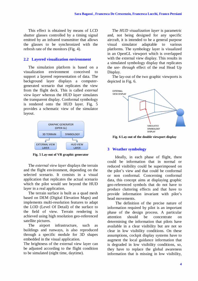
The HUD visualization layer is parametric and, not being designed for any specific aircraft, it is intended to be a general purpose visual simulator adaptable to various platforms. The symbology layer is visualized in an OpenGL viewport which is overlapped with the external view display. This results in a simulated symbology display that replicates the see- through effect of the real Head Up Display.
The lay-out of the two graphic viewports is depicted in Fig. 6.
Fig. 6 Lay-out of the double viewport display
3 Weather symbology
Ideally, in each phase of flight, there could be information that in normal or reduced visibility could be superimposed on the pilot’s view and that could be conformal or non conformal. Concerning conformal data, this concept aims at displaying graphic geo-referenced symbols that do not have to produce cluttering effects and that have to provide information invariant with pilot’s head movements.
The definition of the precise nature of information required by pilot is an important phase of the design process. A particular attention should be concentrate on determining the information that pilots have available in a clear visibility but are not so clear in low visibility conditions. On these assumptions, cockpit display systems have to augment the local guidance information that is degraded in low visibility conditions, so, they have to replace the global awareness information that is missing in low visibility,

5
INNOVATION IN MAN MACHINE INTERFACES: USE OF 3D CONFORMAL SYMBOLS IN THE DESIGN OF FUTURE HUDS (HEAD UP DISPLAYS)
and moreover they have to provide route awareness information that is currently lacking even in clear visibility [7].
Under these preliminary remarks, in our virtual prototype, 3D weather symbols are integrated in a virtual HUD, in order to create a homogeneous environment where pilot can simultaneously take care about flight information and weather events. The aim of this concept is to enhance situation awareness and reduce head down time, using weather radar data.
When an adverse weather event occurs, the pilot is provided with the related information by means of a volumetric 3D area displayed on the HUD. This representative shape indicates the CB. Through this type of symbology, the pilot is expected to intuitively see if the weather event is going to occur in his flight trajectory.
Further symbols are added to the CB shape, in order to indicate which type of weather event is occurring and its intensity.
3.1 CB structure
The presence of a cumulonimbus is visualized into HUD symbology through the definition of a 3D volumetric object, which plays the role of an obstacle to be avoided. Non-physical constraints, such as exclusionary airspace, can be presented in the SVS PFD through a depiction of their boundaries, like physical constraints, such as terrain features. Non-physical constraints, visualized like physical ones, support the pilot in determining guidance in case of a situation that forces the aircraft off the planned path [9].
Weather data, CB position and dimension are taken from a real meteorological event in order to obtain an actual scenario.
Two different typologies of 3D volumetric objects are defined and integrated in the geo-referenced virtual environment. In the first experimental phase, the CB shape has been approximated by a cylinder, while in a second part of our tests, it is represented by a polyhedron. Both representations are then
submitted to an evaluation team, in order to define which of them better indicate the weather event.
A cumulonimbus is commonly indicated by latitude and longitude coordinates which define a polygon and these values are referred to a specific altitude. The idea at the basis of the definition of a 3D volume, consists in using these coordinates to identify a polyhedron, realized by the extrusion of the cross-sectional polygon. Different polyhedrons are realized in accordance to CB’s vertical extension.
As concerns cylinder approach to CB representation, it is realized by an approximation of the polyhedron volume. In this approach the polygon is turned into a circle centered in the center of the polygon and having the same area of the polygon. The cylindrical volume is created by extruding the circle.
3.2 3D Weather symbols
Further information that has been considered in this work is the specific weather phenomena. To this aim, a library of 3D symbols has been created in order to represent and visualize weather conditions in flight operations. In particular, weather chart symbols have been adapted to be rendered as 3D shapes. This approach is expected to take advantage of the pilots’ previous knowledge and is intended for reducing the familiarization time.
In this phase of the work, we selected a set of symbols through which it is possible to represent the most common weather hazards. In following Fig. 7 it is reported, for each weather phenomena, the corresponding weather chart symbol, the associated 3D shape and the related 3D rendering into the virtual HUD.
Thunder and turbulence have been modeled as the tubular shapes generated around their representative polylines. These geometries are not symmetrical. Thus in three dimensions a rendering option was arranged in order to keep the plane they lay on perpendicular to the pilot’s view.

Sara Bagassi , Francesca De Crescenzio, Francesca Lucchi, Franco Persiani
6
Fig. 7 For each weather phenomena (Thunder, Turbulence, Rain, Rain shower, Hail, Icing, Wind shear) the corresponding weather chart symbol, the associated 3D shape and the related 3D rendering into the virtual HUD are reported
The circle, that usually represents the rain
symbol, has been converted into a sphere. The rain shower, which is represented with the triangle, corresponds to the vertex down cone while the hail symbol, typically represented by two triangles, is turned into two cones. The upper cone is vertex up and the lower one is vertex down. The left right arrow that usually represents icing phenomena is converted in a 3D symbol that consists in two cones and a cylinder joint by a Boolean union operator in order to shape a 3D left right arrow. Wind shear is represented by an elliptical hyperboloid. It is intended for bringing the phenomenon actual shape back to mind.
4 Evaluation and discussions
The main issues to be addressed in the evaluation of the proposed interface are:
Symbology readability, with respect to actual distance of the atmospheric hazard from the flight deck.
Clutter level. The evaluation objectives that we intend measuring to validate the concept of displaying 3D conformal symbols onto the HUD are:
The enhancement of the cockpit overall usability.
The improvement of pilot’s SA (Situation Awareness).
In order to perform the evaluation it is necessary to set-up an example scenario to collect suggestions from a focus group.
An airport scenario is represented and visualized in a stereoscopic 3D environment. A HUD configuration is integrated into the model and weather 3D data are projected on it. These features allow to create a virtual 3D environment to be used in the evaluation process.
4.1 Experimental set-up
The flight scenario proposed in the evaluation phase refers to a Northbound approach to Rome Fiumicino airport (Italy). A CB is observed close to the airport: it is approximately centered in: 41,8878 lat; 12,3763 lon. Figg. 8 show the experimental scenario indicating the flight trajectory in blue and the CB horizontal extension: the top part of the CB is depicted in yellow, while the bottom one is in orange. The same scenario is represented in Fig. 8.a by means of polygons, while in Fig. 8.b by means of circles.

7
INNOVATION IN MAN MACHINE INTERFACES: USE OF 3D CONFORMAL SYMBOLS IN THE DESIGN OF FUTURE HUDS (HEAD UP DISPLAYS)
Fig. 8 The experimental scenario is represented. In the top part the CB is described by means of a polygon section, while in the low part it is approximate by a circle
A virtual movie of the approach is made by a virtual camera posed in the flight deck to reproduce what the pilot would see during the approach. Figg. 9 are snapshots taken from a virtual movie generated with the visual application. The white frame inside the picture is the simulated HUD edge. In the HUD a set of non-conformal data is depicted together with the 3D volume of the CB and the weather symbology.
Moreover, low visibility conditions are simulated Figg. 10: in such cases 3D information superimposed on HUD allows pilot to identify a weather hazard even if it is not directly visible.
In Fig 9 and 10 the CB volume is only partially visible, since it refers to a view that is closer to the CB.
Fig 9 A virtual movie is generated in accordance with the described scenario. Snapshots are reported both for polyhedral (in frames 1 and 2) and cylindrical (in frame 3 and 4) CB

Sara Bagassi , Francesca De Crescenzio, Francesca Lucchi, Franco Persiani
8
Fig 10 Low visibility conditions are represented, in order to verify 3D volume perception, also in night or bad weather conditions
While the terrain representation in the two layers is continuous, the HUD symbology is only visible if inside the viewport cone. Since the HUD viewport is smaller than the external view display viewport, all the meteorological events which do not intersect the HUD viewport are not observable from the virtual cockpit even if they intersect the flight trajectory. An additional symbol is added on the HUD to overcome this issue. It consists in a rectangular frame depicted on the top right corner of the HUD indicating the type of weather hazard and its relative position.
Fig. 11.a shows that during the first part of flight the CB is not observable on the HUD. This is due to the fact that the aircraft heading is such that the HUD viewport does not intersect the CB volume. In these cases the symbology shown in Fig 11.b is suggested to be used.
Fig 11 The first frame indicates the aircraft trajectory (in blue) during the approach to Fiumicino airport. When the aircreft is located in the green dot, its flight heading do not allow to see the weather event through the HUD viewport. In such cases a symbology represented in the second frame is suggested to be used
4.2 Evaluation results
In this phase, we intend to validate and evaluate the concept of displaying 3D geo-referenced symbols onto the HUD in our simulator. In particular, we want to investigate about the system capability of providing information with the aim of enhance cockpit usability and improve pilot’s Situation Awareness (SA).
Evaluation process is organized in more phases thanks to the collaboration of a focus group of pilots. At a first phase our concepts and idea are shared with the pilot group in order to let them know about our intent and methods and our system’s architecture. During the first phase of the evaluation, many

9
INNOVATION IN MAN MACHINE INTERFACES: USE OF 3D CONFORMAL SYMBOLS IN THE DESIGN OF FUTURE HUDS (HEAD UP DISPLAYS)
images of our virtual reality based simulator are shown and described to some end user representatives: in particular we focused on the description of concept and prototype objectives. More over we set up a presentation of snapshot and movies in a virtually reconstructed scenario.
Through this phase the members of the focus group are asked to familiarize with it and provide suggestions for the refinement of the prototype.
Finally, we ask them to fill a questionnaires in order to have an objective and measurable feedback about the system’s overall usability and the SA.
The member of the reviewing team evaluate our research as positive, in particular some comments regard the nature of information introduced in HUDs viewport and the way we decide to visualize them. In particular the weather visualized scenario and its real weather context were appreciated, even if it would be important to have more clear information on the HUD about CB intensity.
It has been remarked that the capability to read the instruments is a very important issue to be considered.
A further remark has been made on the use of shaded shapes. Specifically, during the night condition it may result too bright and a wireframe approach could be preferable.
5 Conclusions
The aim of this work is to move the head-down information to an head-up display, in order to reduce pilot attention shift.
3D conformal symbols are suggested to be introduced in HUDs viewport, for weather hazard information.
A stereoscopic virtual environment is set up, and a flight scenario is represented on it. An evaluation phase is performed in order to proof the new symbology confidence in pilot experience.
Development could be performed on this prototype, they concern the refinement of our system and analysis about the possibility of
inserting more 3D conformal information on HUDs.
References
[1] Kramer L J, and Williams S P. Testing the efficiency of synthetic vision during non-normal operations as an enabling technology for equivalent visual operations. Proc of the Human Factors and Ergonomics Society Annual Meeting, Vol. 52, no 19, 1604-1608, September 2008.
[2] Alexander L A, Wickens C D and Hardy T J. Synthetic Vision Systems: the effects of guidance symbology, display size, and field of view. Human Factors and Ergonomics Society, Vol. 47, No. 4, pp 693-707, 2005.
[3] He G, Feyereisen T and Wilson B. Synthetic vision primary flight displays for helicopters. Proc of SPIE, Vol. 6957, 695708, 2008.
[4] Kaber D B, Alexander L A, Stelzer E M, Kim S H, Kaufmann K and Hsiang S. Perceived clutter in advanced cockpit displays: measurement and modeling with experienced pilots. Aviation, Space, and Environmental Medicine, Vol. 79, No. 11, November 2008.
[5] Wickens C D and Long Lt J. Conformal Symbology, attention shift and the Head-Up Display. Proc of the Human Factors and Ergonomics Society Annual Meeting, Vol. 38, no 1, 6-10, October 1994.
[6] Foyle D C, McCann R S and Shelden S G. Attentional issues with superimposed symbology: formats for scene-linked displays. Proc of the 8th International Symposium on Aviation Psychology, Columbus: Ohio State University, 98-103, 1995.
[7] Foyle D C, Andre A D and Hooey B L. Situation Awareness in an Augmented Reality Cockpit: Design, Viewpoints and Cognitive Glue. Proc of the 11th International Conference on Human Computer Interaction, Las Vegas NV, 2005.
[8] Berth C, Hütting G and Lehmann O. Research on integrated collimated cockpit visual and flight information system. Proc of ICAS, the 26th International Conference of the Aeronautical Sciences, Anchorage, AK USA, 2008.
[9] Theunissen E, Koeners G J M, Roefs F D, Rademaker R M, Jinkins R D and Etherington T J. Guidance, Situation Awareness and Integrity Monitoring with an SVS+EVS. Proc of AIAA Guidance, Navigation, and Control Conference and Exhibit, San Francisco California, August 2005.
Sara Bagassi , Francesca De Crescenzio, Francesca Lucchi, Franco Persiani
10
Copyright Statement
The authors confirm that they, and/or their company or organization, hold copyright on all of the original material included in this paper. The authors also confirm that they have obtained permission, from the copyright holder of any third party material included in this paper, to publish it as part of their paper. The authors confirm that they give permission, or have obtained permission from the copyright holder of this paper, for the publication and distribution of this paper as part of the ICAS2012 proceedings or as individual off-prints from the proceedings.