innbox management guide
DESCRIPTION
routerTRANSCRIPT
VDSL2 Home Gateway
Innbox V50-UManagement Guide

Iskratel 2012. All rights reserved.
Technical specifications and features are binding insofar as they are specifically and expressly agreedupon in a written contract.
Technical modifications possible.
Management Guideii
The Table of Contents contains “7” pages.The document contains “70” pages.Document ident. no.: “KSS692500-EDE-020”Document Title: “Management Guide”
Management Guide iii
Safety precautions
When using this equipment, consider the following precautions and requirements:
The following requirements should be fulfilled in order to ensure optimal performance of the device up-to-date technology without any danger of damaging the equipment or the users:
Please read the installation instructions in the User documentation thoroughly before you set up theunit. Correct handling ensures the safety of the user and the equipment.
The device is designed for indoor use. The unit should be used in a sheltered area, within atemperature range from +5 to +40 Celsius.
Do not expose the unit to direct sunlight or other heat sources. The housing and electroniccomponents may be damaged by direct sunlight or heat sources.
Avoid using the device in dusty or damp places and places where there is a risk of explosion.
Do not expose the device to humidity (in a bathroom for example).
When the device is placed close to devices emitting electromagnetic interferences such as amicrowave oven, HiFi equipment, etc., its performance is degraded. Move the device outside thedisturbance range and the modem resumes its normal operation.
Do not try to open or repair the unit yourself. The unit is a complicated electronic device that may berepaired only by authorized and qualified personnel.
Only use the power adapter that comes with the package. Using a different voltage rating poweradapter may damage this unit.
Place this unit on a stable surface or mount it on the wall.
Disconnect the power adapter before moving the unit.
Do not put the cables where people can fall over them.
Keep the package out of reach of children.
Fiber cable, when operating, transmits a beam of infrared laser light You shall not lookat the optical cable if it is at one side connected to the optical transmitter while the otherend is not connected.
Voltage: When handling the power supply system, follow the instructions for safe use,which are part of the power-supply user manual.
Sensitivity to static electricity: To protect the equipment sensitive to static electricityalways use an antistatic wrist-strap.
For an even higher level of protection, we recommend that you equip the room withantistatic floor, and wear an antistatic overall, cotton gloves and conducting footwear.

Management Guideiv
Management Guide v
Contents
Document D Management Guide
1 About this document .............................................................................................. 1
1.1 Purpose ............................................................................................................................................ 1
1.2 Intended audience ........................................................................................................................... 1
1.3 Document organization................................................................................................................... 1
1.4 Conventions..................................................................................................................................... 1
1.4.1 Additional text marking ............................................................................................................... 1
1.4.2 Graphical user interface (GUI).................................................................................................... 2
2 Starting the WEB management interface.............................................................. 3
2.1 Navigation ........................................................................................................................................ 4
3 WEB management interface description .............................................................. 4
3.1 Device info........................................................................................................................................ 5
3.1.1 Summary .................................................................................................................................... 5
3.2 Advanced Setup............................................................................................................................... 6
3.2.1 Layer2 Interface.......................................................................................................................... 63.2.1.1 ATM Interface........................................................................................................................ 6
3.2.1.1.1 ATM PVC configuration ...................................................................................................................73.2.1.2 PTM Interface........................................................................................................................ 8
3.2.1.2.1 PTM configuration............................................................................................................................83.2.1.3 ETH Interface ....................................................................................................................... 9
3.2.1.3.1 ETH WAN Configuration..................................................................................................................9
3.2.2 WAN Service ........................................................................................................................... 103.2.2.1 WAN Service Interface configuration ................................................................................. 10
3.2.3 LAN........................................................................................................................................... 14
3.2.4 NAT .......................................................................................................................................... 153.2.4.1 Virtual Servers..................................................................................................................... 15
3.2.4.1.1 NAT -- Virtual servers ....................................................................................................................163.2.4.2 Port Triggering..................................................................................................................... 17
3.2.4.2.1 NAT -- Port Triggering ...................................................................................................................173.2.4.3 DMZ Host ............................................................................................................................ 18
3.2.5 Security..................................................................................................................................... 183.2.5.1 IP Filtering ........................................................................................................................... 18
3.2.5.1.1 Outgoing IP filtering .......................................................................................................................193.2.5.1.2 Incoming IP Filtering ......................................................................................................................20
3.2.5.2 MAC Filtering....................................................................................................................... 223.2.5.2.1 Add MAC Filter ..............................................................................................................................23
3.2.6 Parental Control........................................................................................................................ 233.2.6.1 Time Restriction .................................................................................................................. 24
3.2.6.1.1 Access Timer Restriction ...............................................................................................................243.2.6.2 URL Filter ............................................................................................................................ 25
3.2.6.2.1 Parental Control -- URL Filter Add.................................................................................................25
3.2.7 Quality of Service ..................................................................................................................... 263.2.7.1 QoS Queue Setup ............................................................................................................... 27
3.2.7.1.1 QoS Queue Configuration .............................................................................................................283.2.7.2 QoS Classification ............................................................................................................... 28
3.2.7.2.1 Add Network Traffic Class Rule.....................................................................................................29
Management Guidevi
3.2.8 Routing ..................................................................................................................................... 293.2.8.1 Default Gateway .................................................................................................................. 303.2.8.2 Static Route ......................................................................................................................... 30
3.2.8.2.1 Routing -- Static Route Add...........................................................................................................313.2.8.3 Policy Routing...................................................................................................................... 31
3.2.8.3.1 Policy Routing Setup .....................................................................................................................323.2.8.4 RIP....................................................................................................................................... 32
3.2.9 DNS .......................................................................................................................................... 333.2.9.1 DNS Server.......................................................................................................................... 333.2.9.2 Dynamic DNS ...................................................................................................................... 34
3.2.9.2.1 Add Dynamic DNS.........................................................................................................................35
3.2.10 DSL........................................................................................................................................... 36
3.2.11 UPnP ........................................................................................................................................ 37
3.2.12 DNS Proxy ................................................................................................................................ 38
3.2.13 Interface Grouping .................................................................................................................... 383.2.13.1 Interface Grouping Configuration......................................................................................... 39
3.2.14 Port Configuration..................................................................................................................... 40
3.2.15 Multicast.................................................................................................................................... 41
3.3 Wireless .......................................................................................................................................... 42
3.3.1 Basic ......................................................................................................................................... 42
3.3.2 Security ..................................................................................................................................... 433.3.2.1 Manual Setup AP................................................................................................................. 44
3.3.2.1.1 WEP...............................................................................................................................................453.3.2.1.2 WPA...............................................................................................................................................473.3.2.1.3 WPA-PSK ......................................................................................................................................483.3.2.1.4 WPA2.............................................................................................................................................493.3.2.1.5 WPA2-PSK ....................................................................................................................................503.3.2.1.6 Mixed WPA2/WPA.........................................................................................................................513.3.2.1.7 Mixed WPA2/WPA-PSK ................................................................................................................52
3.3.2.2 WPS Setup .......................................................................................................................... 53
3.3.3 MAC Filter ................................................................................................................................. 543.3.3.1 Wireless -- MAC Filter.......................................................................................................... 54
3.3.4 Wireless Bridge......................................................................................................................... 55
3.3.5 Advanced.................................................................................................................................. 56
3.3.6 Station info................................................................................................................................ 57
3.4 Voice ............................................................................................................................................... 58
3.4.1 SIP Basic Settings .................................................................................................................... 58
3.4.2 SIP Advanced Settings ............................................................................................................. 60
3.4.3 SIP Debug Settings .................................................................................................................. 62
3.5 Diagnostics..................................................................................................................................... 63
3.5.1 Diagnostics ............................................................................................................................... 63
3.6 Management ................................................................................................................................... 64
3.6.1 Settings - Backup...................................................................................................................... 64
3.6.2 Update settings......................................................................................................................... 65
3.6.3 Restore Default settings ........................................................................................................... 65
3.6.4 System Log............................................................................................................................... 663.6.4.1 System Log Configuration ................................................................................................... 66
3.6.5 Security Log.............................................................................................................................. 67

Management Guide vii
3.6.6 TR-069 Client ........................................................................................................................... 67
3.6.7 Internet Time ............................................................................................................................ 68
3.6.8 Access Control - Passwords..................................................................................................... 69
3.6.9 Update Software....................................................................................................................... 69
3.6.10 Reboot ...................................................................................................................................... 70

About this document 1
1 About this document
1.1 Purpose
This document contains a description of the web interface for configuring and managing the Innbox V50-Uhome gateway.
1.2 Intended audience
This document is intended for the administrators and maintenance staff.
1.3 Document organization
1.4 Conventions
1.4.1 Additional text marking
Table 1-1: Document organization
Chapter... Describes...
“Starting the web management interface”
the web interface start-up procedure.
“Web managemet interface description”
the web interface navigation, pages, sections and management optionsthat are available for administrators and maintanance staff.
Table 1-2: Conventions for text marking
Sign Description Definition
Warning The sign draws attention to a text that must be read and considered in order to avoid harmful consequences.
Note The sign draws attention to an additional explanation.
D. Management guide2
1.4.2 Graphical user interface (GUI)
Table 1-3: Conventions for GUI text formatting
Format Description
element Elements of the application windows: window and dialog box titles, menus, data fields, buttons, tabs...
value Value you must choose or enter.
>
The > sign links: sequence of menu choices which you have to select, for example: Node >
Insert.
sequence of MN manager, one or more element’s groups and element, whichyou have to select, for example: SYS > Basic Administration > Node.
Table 1-4: Conventions for mouse usage in GUI
Format Description
Click Select and release the primary mouse button without moving the pointer.
Double-click Press the primary mouse button twice continuously and quickly without moving the pointer.
Drag Press and hold the primary mouse button and move the pointer to a certain position.
Right-click Press the right mouse button without moving the pointer.
Starting the WEB management interface 3
2 Starting the WEB management interface
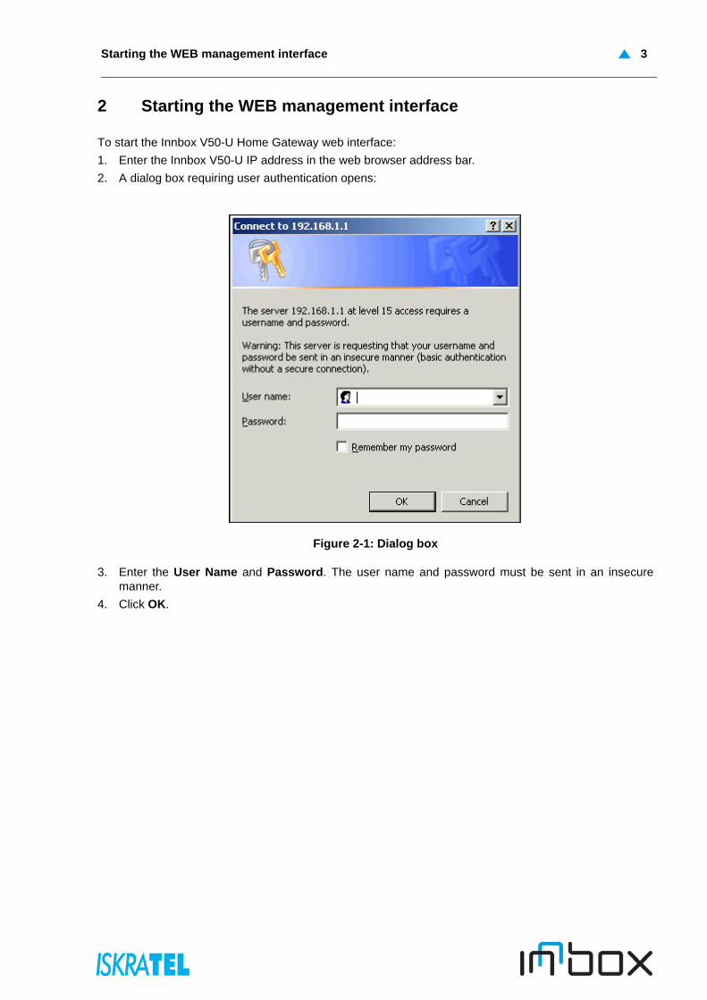
To start the Innbox V50-U Home Gateway web interface:
1. Enter the Innbox V50-U IP address in the web browser address bar.
2. A dialog box requiring user authentication opens:
Figure 2-1: Dialog box
3. Enter the User Name and Password. The user name and password must be sent in an insecuremanner.
4. Click OK.
D. Management guide4
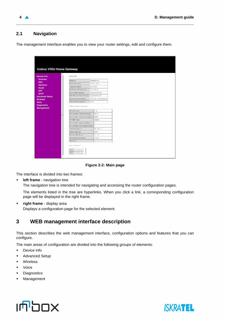
2.1 Navigation
The management interface enables you to view your router settings, edit and configure them.
Figure 2-2: Main page
The interface is divided into two frames:
left frame - navigation tree
The navigation tree is intended for navigating and accessing the router configuration pages.
The elements listed in the tree are hyperlinks. When you click a link, a corresponding configurationpage will be displayed in the right frame.
right frame - display area
Displays a configuration page for the selected element.
3 WEB management interface description
This section describes the web management interface, configuration options and features that you canconfigure.
The main areas of configuration are divided into the following groups of elements:
Device info
Advanced Setup
Wireless
Voice
Diagnostics
Management
Device info 5
3.1 Device info
This section introduces the basic information about the device and its current settings in use. Click any ofthe submenus to view the corresponding information.
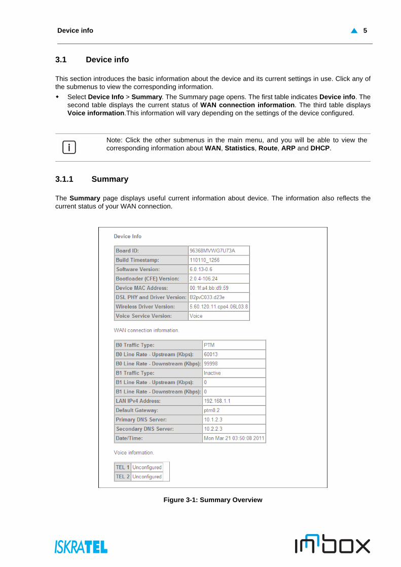
Select Device Info > Summary. The Summary page opens. The first table indicates Device info. Thesecond table displays the current status of WAN connection information. The third table displaysVoice information.This information will vary depending on the settings of the device configured.
3.1.1 Summary
The Summary page displays useful current information about device. The information also reflects thecurrent status of your WAN connection.
Figure 3-1: Summary Overview
Note: Click the other submenus in the main menu, and you will be able to view thecorresponding information about WAN, Statistics, Route, ARP and DHCP.
D. Management guide6
3.2 Advanced Setup
Select Advanced Setup. Click any of the submenus to configure the corresponding function, for exampleLayer2 Interface, WAN Service, LAN, NAT, Security, Parental Control, Quality of Service, Routing, DNS,DSL, UPnP, DNS Proxy, Interface Grouping, Port Configuration and Multicast.
3.2.1 Layer2 Interface
Select Advanced Setup > Layer2 Interface. You can configure:
ATM Interface: Configure the device to access Internet as a ADSL user. ISP provides you VPI (VirtualPath Identifier), VCI (Virtual Channel Identifier) settings and the DSL Interface with RJ11 connector.
PTM Interface: Configure the device to access Internet as a VDSL user. Packet Transfer Mode (PTM)transports packets (IP, PPP, Ethernet, etc.) over DSL links as an alternative to using AsynchronousTransfer Mode (ATM). PTM is based on the Ethernet in the First Mile (EFM) IEEE802.3ah standard.
ETH Interface: Configure the device to access Internet as an Ethernet user. ISP provides youBroadband Internet Service and the Ethernet Interface with RJ45 or SC/LC optical connector.
3.2.1.1 ATM Interface
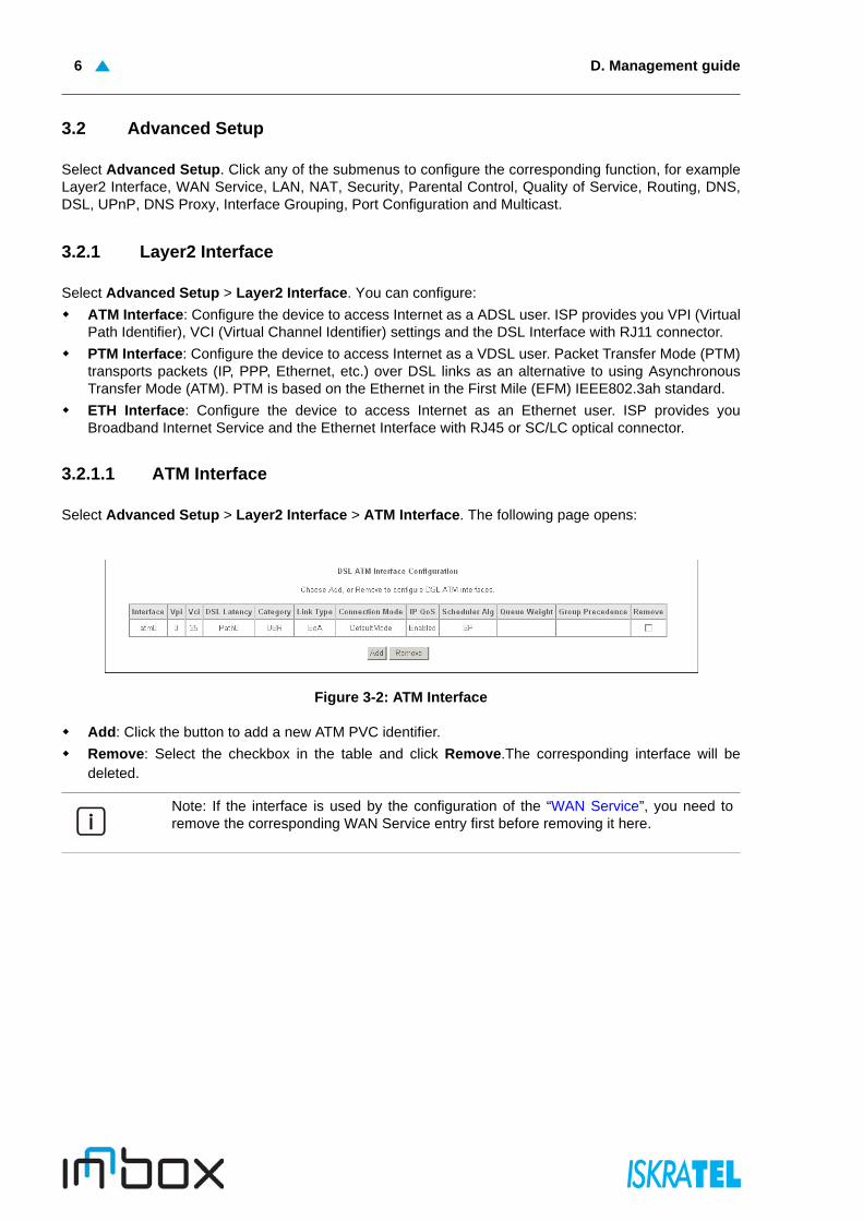
Select Advanced Setup > Layer2 Interface > ATM Interface. The following page opens:
Figure 3-2: ATM Interface
Add: Click the button to add a new ATM PVC identifier.
Remove: Select the checkbox in the table and click Remove.The corresponding interface will bedeleted.
Note: If the interface is used by the configuration of the “WAN Service”, you need toremove the corresponding WAN Service entry first before removing it here.

ATM PVC configuration 7
3.2.1.1.1 ATM PVC configuration
Select Advanced Setup > Layer2 Interface > ATM Interface > Add.
Figure 3-3: ATM PVC Configuration page
VPI/VCI: the VPI and VCI values provided by your ISP. Do not change them unless it was required byyour ISP.
DSL Latency: Select a DSL latency. The options include Path 0 and Path1.
DSL Link Type: Select a DSL Link Type which is provided by your ISP. The options include EoA (it isfor PPPoE, IPoE, and Bridge), PPPoA (PPP over ATM) and IPoA (IP over ATM).
Connection Mode: Select the connection mode for EoA option of DSL Link Type. The options includeDefault mode for single service over one connection, VLAN MUX Mode for multiple Vlan service overone connection, and MSC Mode for Multiple Service over one connection.
Service Category: Select the type of the service assigned by your ISP in the drop-down list. Thedefault type is UBR Without PCR.
Encapsulation Mode: The mode of the data processing over the Link Type you have selected. Usesthe default setting, if you are not sure.
Select IP QoS Scheduler Algorithm: If you want to adopt QoS (Quality of Service) for theconnection, select Strict Priority or Weighted Fair Queuing.
Note: Enabling packet level QoS for PVC improves performance for selected classes ofapplications. While QoS consumes system resources; therefore the number of PVC(s)will be reduced. Besides this, it cannot be set for the connection type of CBR and Real-time VBR. If you select the QoS service, the Quality of Service menu will be added tothe Web-based Utility, the detailed configuration will be described in “Quality of Service”.

D. Management guide8
3.2.1.2 PTM Interface
Select Advanced Setup > Layer2 Interface > PTM Interface. The following page opens:
Figure 3-4: PTM Interface
Add: Click the button to add a new interface.
Remove: Select the checkbox in the table on the page above and then click Remove. Thecorresponding interface will be deleted.
3.2.1.2.1 PTM configuration
Select Advanced Setup > Layer2 Interface > PTM Interface > Add.
Figure 3-5: PTM Configuration page
DSL Latency: Select a DSL latency. The options include Path 0 and Path1.
PTM Priority: Select a PTM Priority.The options include Normal Priority and High Priority.
Connection Mode: Select the connection mode for EoA option of DSL Link Type. The options includeDefault mode for single service over one connection, VLAN MUX Mode for multiple Vlan service overone connection, and MSC Mode for Multiple Service over one connection.

ETH Interface 9
Select IP QoS Scheduler Algorithm: If you want to adopt QoS (Quality of Service) for theconnection, select Strict Priority or Weighted Fair Queuing.
3.2.1.3 ETH Interface
Select Advanced Setup > Layer2 Interface > ETH Interface. The following page opens:
Figure 3-6: ETH WAN Interface
Add: Click the button to add a new interface.
Apply/Save: Click the button to save your settings.
3.2.1.3.1 ETH WAN Configuration
Select Advanced Setup > Layer2 Interface > ETH Interface > Add. The following page opens:
Figure 3-7: ETH WAN Configuration page
ETH port: Select an ETH port to configure as the WAN port.
Select Connection Mode: Select a connection mode for the port:
• Default mode - Single service over one connection.
• VLAN MUX Mode - Multiple Vlan service over one connection.
D. Management guide10
3.2.2 WAN Service
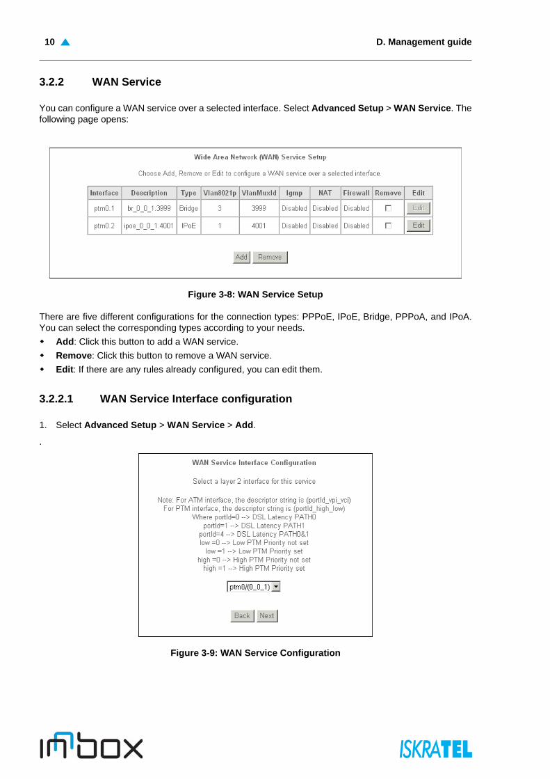
You can configure a WAN service over a selected interface. Select Advanced Setup > WAN Service. Thefollowing page opens:
Figure 3-8: WAN Service Setup
There are five different configurations for the connection types: PPPoE, IPoE, Bridge, PPPoA, and IPoA.You can select the corresponding types according to your needs.
Add: Click this button to add a WAN service.
Remove: Click this button to remove a WAN service.
Edit: If there are any rules already configured, you can edit them.
3.2.2.1 WAN Service Interface configuration
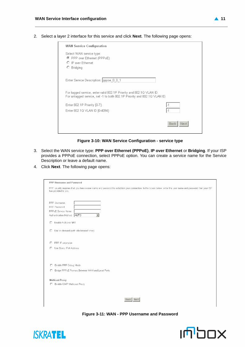
1. Select Advanced Setup > WAN Service > Add.
.
Figure 3-9: WAN Service Configuration
WAN Service Interface configuration 11
2. Select a layer 2 interface for this service and click Next. The following page opens:
Figure 3-10: WAN Service Configuration - service type
3. Select the WAN service type: PPP over Ethernet (PPPoE), IP over Ethernet or Bridging. If your ISPprovides a PPPoE connection, select PPPoE option. You can create a service name for the ServiceDescription or leave a default name.
4. Click Next. The following page opens:
Figure 3-11: WAN - PPP Username and Password
D. Management guide12
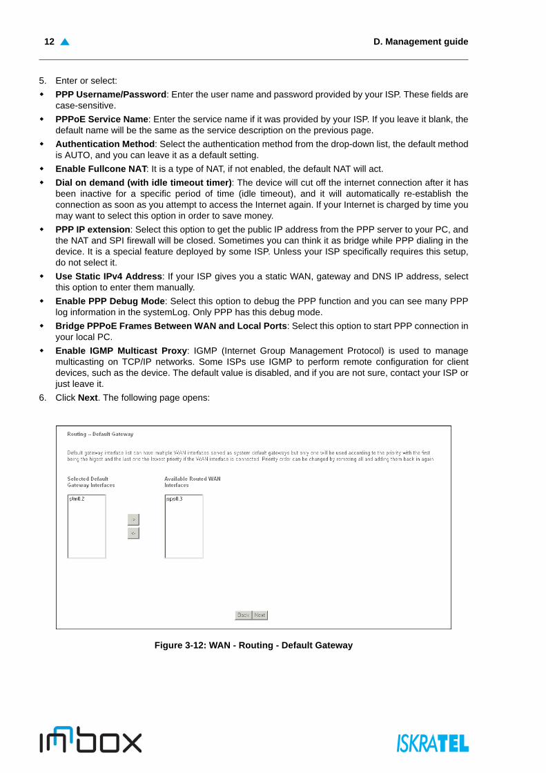
5. Enter or select:
PPP Username/Password: Enter the user name and password provided by your ISP. These fields arecase-sensitive.
PPPoE Service Name: Enter the service name if it was provided by your ISP. If you leave it blank, thedefault name will be the same as the service description on the previous page.
Authentication Method: Select the authentication method from the drop-down list, the default methodis AUTO, and you can leave it as a default setting.
Enable Fullcone NAT: It is a type of NAT, if not enabled, the default NAT will act.
Dial on demand (with idle timeout timer): The device will cut off the internet connection after it hasbeen inactive for a specific period of time (idle timeout), and it will automatically re-establish theconnection as soon as you attempt to access the Internet again. If your Internet is charged by time youmay want to select this option in order to save money.
PPP IP extension: Select this option to get the public IP address from the PPP server to your PC, andthe NAT and SPI firewall will be closed. Sometimes you can think it as bridge while PPP dialing in thedevice. It is a special feature deployed by some ISP. Unless your ISP specifically requires this setup,do not select it.
Use Static IPv4 Address: If your ISP gives you a static WAN, gateway and DNS IP address, selectthis option to enter them manually.
Enable PPP Debug Mode: Select this option to debug the PPP function and you can see many PPPlog information in the systemLog. Only PPP has this debug mode.
Bridge PPPoE Frames Between WAN and Local Ports: Select this option to start PPP connection inyour local PC.
Enable IGMP Multicast Proxy: IGMP (Internet Group Management Protocol) is used to managemulticasting on TCP/IP networks. Some ISPs use IGMP to perform remote configuration for clientdevices, such as the device. The default value is disabled, and if you are not sure, contact your ISP orjust leave it.
6. Click Next. The following page opens:
Figure 3-12: WAN - Routing - Default Gateway
WAN Service Interface configuration 13
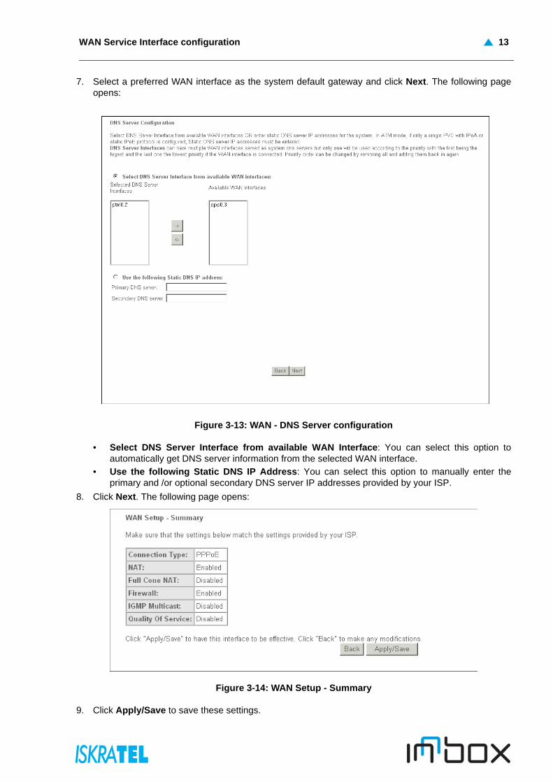
7. Select a preferred WAN interface as the system default gateway and click Next. The following pageopens:
Figure 3-13: WAN - DNS Server configuration
• Select DNS Server Interface from available WAN Interface: You can select this option toautomatically get DNS server information from the selected WAN interface.
• Use the following Static DNS IP Address: You can select this option to manually enter theprimary and /or optional secondary DNS server IP addresses provided by your ISP.
8. Click Next. The following page opens:
Figure 3-14: WAN Setup - Summary
9. Click Apply/Save to save these settings.
D. Management guide14
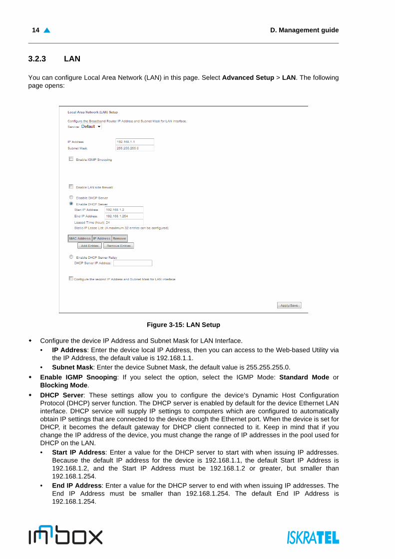
3.2.3 LAN
You can configure Local Area Network (LAN) in this page. Select Advanced Setup > LAN. The followingpage opens:
Figure 3-15: LAN Setup
Configure the device IP Address and Subnet Mask for LAN Interface.
• IP Address: Enter the device local IP Address, then you can access to the Web-based Utility viathe IP Address, the default value is 192.168.1.1.
• Subnet Mask: Enter the device Subnet Mask, the default value is 255.255.255.0.
Enable IGMP Snooping: If you select the option, select the IGMP Mode: Standard Mode orBlocking Mode.
DHCP Server: These settings allow you to configure the device‘s Dynamic Host ConfigurationProtocol (DHCP) server function. The DHCP server is enabled by default for the device Ethernet LANinterface. DHCP service will supply IP settings to computers which are configured to automaticallyobtain IP settings that are connected to the device though the Ethernet port. When the device is set forDHCP, it becomes the default gateway for DHCP client connected to it. Keep in mind that if youchange the IP address of the device, you must change the range of IP addresses in the pool used forDHCP on the LAN.
• Start IP Address: Enter a value for the DHCP server to start with when issuing IP addresses.Because the default IP address for the device is 192.168.1.1, the default Start IP Address is192.168.1.2, and the Start IP Address must be 192.168.1.2 or greater, but smaller than192.168.1.254.
• End IP Address: Enter a value for the DHCP server to end with when issuing IP addresses. TheEnd IP Address must be smaller than 192.168.1.254. The default End IP Address is192.168.1.254.

NAT 15
• Leased Time (hour): The Leased Time is the amount of time in which a network user will beallowed connection to the device with their current dynamic IP address. Enter the amount of time,in hours, then the user will be “leased” this dynamic IP address. After the dynamic IP address hasexpired, the user will be automatically assigned a new dynamic IP address. The default is 24hours.
Static IP Lease List: The function allows you to specify a reserved IP address for a PC on the LAN,that PC will always obtain the assigned IP address each time when it accesses the DHCP server.Reserved IP addresses should be assigned to servers that require permanent IP settings. Click AddEntries, to reserve the MAC address and IP address you want to reserved.
Configure the second IP Address and Subnet Mask: Configure the device second IP Address andSubnet Mask for LAN Interface through which you can also access to the Web-based Utility as thedefault IP Address and Subnet Mask.
3.2.4 NAT
Network Address Translation (NAT) implements the translation of network addresses and ports. Theimplementation also supports NAT plus. Support for additional services is enabled, e.g., H.323, Video &Audio on Demand, which use a more complicated server-client communication scheme.
The following NAT features can be configured:
“Virtual Servers”
“Port Triggering”
“DMZ Host”
3.2.4.1 Virtual Servers
Virtual servers can be used for setting up public services on your LAN, such as DNS, Email and FTP. Avirtual server is defined as a service port, and all requests from the Internet to this service port will beredirected to the computer specified by the server IP. Any PC that was used for a virtual server must havea static or reserved IP Address because its IP Address may change when using the DHCP function.
Select Advanced Setup > NAT > Virtual Servers. The following page opens:
Figure 3-16: Virtual Servers
Virtual Server Table indicates the information about the Virtual Server entries:
Server Name: The name of the virtual server. It is exclusive and must be filled in.
External Port Start: The base number of external ports. You can type a service port or leave it blank.
External Port End: The end number of external ports. You can type a service port or leave it blank.
Protocol: The protocol used for this application, TCP, UDP, or TCP/UDP.
Note: UPnP, DHCP Server and the second IP Address are not available for theconnection type of Bridging. They will not display on the preceding page since onlyBridging is selected.
D. Management guide16
Internal Port Start: The base number of internal ports. You can type a service port or leave it blank.
Internal Port End: The end number of internal ports. You can type a service port or leave it blank.
Server IP Address: The IP Address of the PC providing the service application.
WAN Interface: The WAN service interface providing the service application.
Add: Click this button to add a virtual server.
Remove: Click this button to remove a virtual server.
3.2.4.1.1 NAT -- Virtual servers
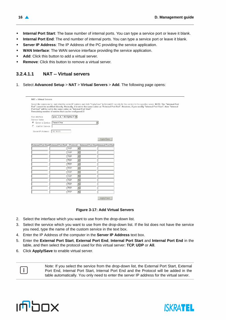
1. Select Advanced Setup > NAT > Virtual Servers > Add. The following page opens:
Figure 3-17: Add Virtual Servers
2. Select the interface which you want to use from the drop-down list.
3. Select the service which you want to use from the drop-down list. If the list does not have the serviceyou need, type the name of the custom service in the text box.
4. Enter the IP Address of the computer in the Server IP Address text box.
5. Enter the External Port Start, External Port End, Internal Port Start and Internal Port End in thetable, and then select the protocol used for this virtual server: TCP, UDP or All.
6. Click Apply/Save to enable virtual server.
Note: If you select the service from the drop-down list, the External Port Start, ExternalPort End, Internal Port Start, Internal Port End and the Protocol will be added in thetable automatically. You only need to enter the server IP address for the virtual server.

Port Triggering 17
3.2.4.2 Port Triggering
Some applications require that specific ports in the device firewall should be opened for access by remotedevices. Port Trigger dynamically opens up the 'Open Ports' in the firewall when an application on the LANinitiates a TCP/UDP connection to a remote device using the triggering ports. The device allows theremote party from the WAN side to establish new connections back to the application on the LAN sideusing the open ports. A maximum 32 entries can be configured.
Select Advanced Setup > NAT > Port Triggering. The following page opens:
Figure 3-18: Port Triggering
Port Triggering Table: The table indicates the information about the port triggering entries.
• Application Name: This is the name of the port triggering. It is exclusive and must be filled.
• Trigger: It includes the Protocol and the Start and End value of the Trigger ports.
• Open: It includes the Protocol and the Start and End value of the Open ports.
• WAN Interface: The WAN service interface setting the port triggering.
Add: Click the button to add a new entry.
Remove: Click the button to remove an entry.
3.2.4.2.1 NAT -- Port Triggering
1. Select Advanced Setup > NAT > Port Triggering > Add. The following page opens:
Figure 3-19: Add Port Triggering

D. Management guide18
2. Select the application from the drop-down list. If the list does not have the application that you want,select the Custom application radio button, and type the name of the custom application in the textbox.
3. Enter the Trigger Port Start, Trigger Port End, Open Port Start and Open Port End in the table,and then select the Trigger protocol and Open protocol: TCP, UDP or All.
4. Click Save/Apply to enable the settings.
3.2.4.3 DMZ Host
The DMZ host feature can make a local host be exposed to the Internet for a special-purpose service,such as online gaming or video conferences.The device will forward IP packets from the WAN that do notbelong to any of the applications configured in the virtual servers table to the DMZ host computer.
Select Advanced Setup > NAT > DMZ Host. The following page opens:
Figure 3-20: DMZ Host
DMZ Host IP Address:
• Enter the DMZ host IP address and click Apply to activate the DMZ host
• Clear the IP address field and click Apply to deactivate the DMZ host.
3.2.5 Security
The advanced security features prevent other computers on the Internet from connecting to your PCs. Youshould only change the default security settings if you have experience in network configuration. In mostcases you will not need to make any changes.
The following security features can be configured: IP filtering and MAC filtering.
3.2.5.1 IP Filtering
The IP address filtering feature makes it possible for administrators to control user access to the Internet,which is based on user IP. The IP address filtering includes: Outgoing IP filtering and Incoming IPfiltering.
Note: If you select the application from the drop-down list, the External Port Start,External Port End, Internal Port Start, Internal Port End and the Protocol will be added inthe table automatically.
Note: DMZ host forwards all the ports at the same time. Any PC whose port is beingforwarded must have its DHCP client function disabled and should have a new static IPAddress assigned to it because its IP Address may change while using the DHCPfunction.

Outgoing IP filtering 19
3.2.5.1.1 Outgoing IP filtering
The Outgoing IP Filtering feature allows you to control some IP traffic from LAN to access specificaddresses. By default, all outgoing IP traffic from LAN is allowed, but some IP traffic can be BLOCKED bysetting up filters.
Select Advanced Setup > Security > IP Filtering > Outgoing. The following page opens.
Figure 3-21: Outgoing IP Filtering
Add: Click this button to add an outgoing IP filter.
Remove: Click this button to remove an outgoing IP filter.
Add IP filter -- Outgoing
1. Select Advanced Setup > Security > IP Filtering > Outgoing > Add. The following page opens:
Figure 3-22: Add IP Filter - Outgoing
2. Enter the Filter name for the rule, it is exclusive and must be filled.
3. Select the protocol TCP/UDP, TCP, UDP or ICMP in the drop-down list for the connection between thesource IP address and destination IP address.
4. Enter a Source IP address in dotted-decimal notation format and then type the Source Port (port orport: port) in the text boxes separately.
5. Enter a Destination IP address in dotted-decimal notation format and then type the Destination Port(port or port: port) in the text boxes separately.
6. Click Apply/Save to save this entry.

D. Management guide20
3.2.5.1.2 Incoming IP Filtering
The Incoming IP Filtering feature allows some IP traffic from WAN to access some local addresses. Bydefault, all incoming IP traffic from the WAN is blocked when the firewall is enabled. However, some IPtraffic can be ACCEPTED by setting up filters.
Select Advanced Setup > Security > IP Filtering > Incoming. The following page opens.
Figure 3-23: Incoming IP Filtering
Add: Click this button to add an incoming IP filter.
Remove: Click this button to remove an incoming IP filter.
Note: When you add an Outgoing IP Filtering entry, you must configure at least onecondition on the preceding page except the Filter name. If you leave the Protocol blank,it means that the rule is effective to all protocols, if you leave the Source IP Addressand/or Destination IP Address blank, it suggests that all Source IP Addresses and/orDestination IP Addresses are controlled by the rule, if you leave the Source Port and/orDestination Port blank, it suggests that all Source Ports and/or Destination Ports arecontrolled by the rule.

Incoming IP Filtering 21
Add IP filter -- Incoming
1. Select Advanced Setup > Security > IP Filtering > Incoming > Add. The following page opens:
Figure 3-24: Add IP Filter - Incoming
2. Enter the Filter name for the rule, it is exclusive and must be filled in.
3. Select Protocol in the drop-down list, enter Source IP address, Source Port, Destination IPaddress and Destination Port for the rule.
4. Select at least one WAN interfaces displayed in the page to apply this rule.
5. Click Apply/Save to save this entry.
Note: When you add an Incoming IP Filtering entry, you must configure at least onecondition on the preceding page except the Filter name. If you leave Protocol blank, itmeans that the rule is effective to all protocols, if you leave the Source IP address and/or Destination IP address blank, it suggests that all Source IP addresses and/orDestination IP addresses are controlled by the rule, if you leave the Source Port and/orDestination Port blank, it suggests that all Source Ports and/or Destination Ports arecontrolled by the rule.
D. Management guide22
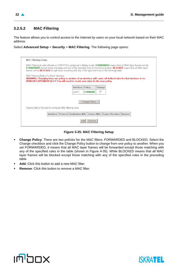
3.2.5.2 MAC Filtering
The feature allows you to control access to the Internet by users on your local network based on their MACaddress.
Select Advanced Setup > Security > MAC Filtering. The following page opens:
Figure 3-25: MAC Filtering Setup
Change Policy: There are two policies for the MAC filters: FORWARDED and BLOCKED. Select theChange checkbox and click the Change Policy button to change from one policy to another. When youset FORWARDED, it means that all MAC layer frames will be forwarded except those matching withany of the specified rules in the table (shown in Figure 4-35). While BLOCKED means that all MAClayer frames will be blocked except those matching with any of the specified rules in the precedingtable.
Add: Click this button to add a new MAC filter.
Remove: Click this button to remove a MAC filter.

Add MAC Filter 23
3.2.5.2.1 Add MAC Filter
1. Select Advanced Setup > Security > MAC Filtering > Add. The following page opens:
Figure 3-26: Add MAC Filter
2. Select Protocol Type in the drop-down list for the rule.
3. Enter Destination MAC Address and Source MAC Address in the fields.
4. Select Frame Direction in the drop-down list for the rule.
5. Select the WAN interfaces from the drop-down list.
6. Click Save/Apply to save this entry.
3.2.6 Parental Control
Parental Control feature provides the facility to block WAN side access from the specified internal PCs inyour network for a specified duration as configured by the user (Parent or administrator).
Many parents want to have some control over the Internet access of their children’s PCs. The ParentalControl feature enables a time based controlling feature. It gives the control to the parents/administratorsto control the traffic from different internal PCs connected to device.
You can configure Time Restriction and URL Filter.
D. Management guide24
3.2.6.1 Time Restriction
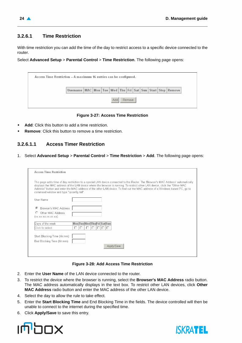
With time restriction you can add the time of the day to restrict access to a specific device connected to therouter.
Select Advanced Setup > Parental Control > Time Restriction. The following page opens:
Figure 3-27: Access Time Restriction
Add: Click this button to add a time restriction.
Remove: Click this button to remove a time restriction.
3.2.6.1.1 Access Timer Restriction
1. Select Advanced Setup > Parental Control > Time Restriction > Add. The following page opens:
Figure 3-28: Add Access Time Restriction
2. Enter the User Name of the LAN device connected to the router.
3. To restrict the device where the browser is running, select the Browser's MAC Address radio button.The MAC address automatically displays in the text box. To restrict other LAN devices, click OtherMAC Address radio button and enter the MAC address of the other LAN device.
4. Select the day to allow the rule to take effect.
5. Enter the Start Blocking Time and End Blocking Time in the fields. The device controlled will then beunable to connect to the internet during the specified time.
6. Click Apply/Save to save this entry.
URL Filter 25
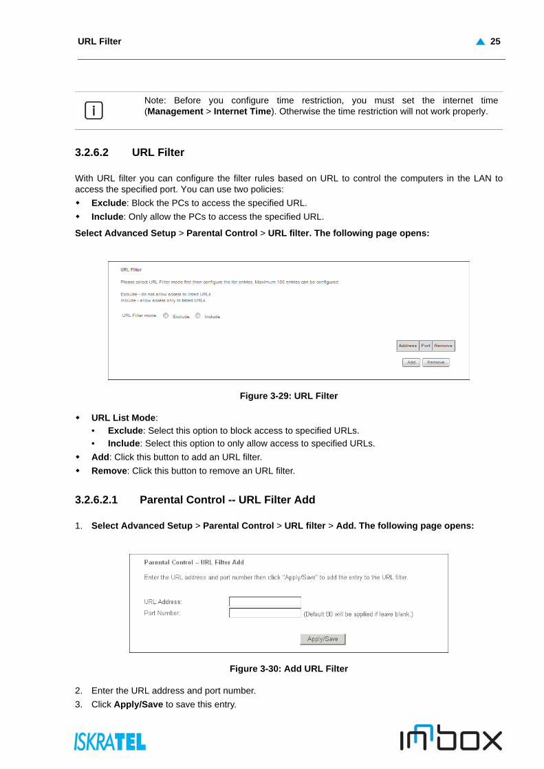
3.2.6.2 URL Filter
With URL filter you can configure the filter rules based on URL to control the computers in the LAN toaccess the specified port. You can use two policies:
Exclude: Block the PCs to access the specified URL.
Include: Only allow the PCs to access the specified URL.
Select Advanced Setup > Parental Control > URL filter. The following page opens:
Figure 3-29: URL Filter
URL List Mode:
• Exclude: Select this option to block access to specified URLs.
• Include: Select this option to only allow access to specified URLs.
Add: Click this button to add an URL filter.
Remove: Click this button to remove an URL filter.
3.2.6.2.1 Parental Control -- URL Filter Add
1. Select Advanced Setup > Parental Control > URL filter > Add. The following page opens:
Figure 3-30: Add URL Filter
2. Enter the URL address and port number.
3. Click Apply/Save to save this entry.
Note: Before you configure time restriction, you must set the internet time(Management > Internet Time). Otherwise the time restriction will not work properly.
D. Management guide26
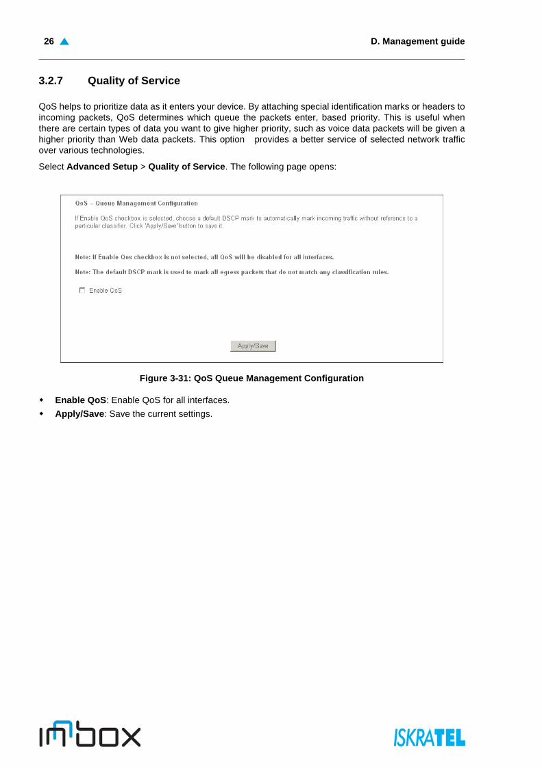
3.2.7 Quality of Service
QoS helps to prioritize data as it enters your device. By attaching special identification marks or headers toincoming packets, QoS determines which queue the packets enter, based priority. This is useful whenthere are certain types of data you want to give higher priority, such as voice data packets will be given ahigher priority than Web data packets. This option provides a better service of selected network trafficover various technologies.
Select Advanced Setup > Quality of Service. The following page opens:
Figure 3-31: QoS Queue Management Configuration
Enable QoS: Enable QoS for all interfaces.
Apply/Save: Save the current settings.
QoS Queue Setup 27
3.2.7.1 QoS Queue Setup
Configure the QoS queues.
Select Advanced Setup > Quality of Service > Queue Config. The following page opens:
Figure 3-32: QoS Queue Setup
Add: Click this button to add a QoS queue.
Enable: Click the checkbox in the Enable column and then this button to enable the specified queue.
Remove: Click the checkbox in the Remove column and then this button to remove the specifiedqueue.
D. Management guide28
3.2.7.1.1 QoS Queue Configuration
Configure a QoS queue and assign it to a specific layer2 interface.
1. Select Advanced Setup > Quality of Service > Queue Config > Add. The following page opens:
Figure 3-33: QoS Queue Configuration
2. Enter the Name of the queues.
3. To enable the queue, select Enable.
4. In the Interface drop-down list select the interface to assign the queue to.
5. Click Apply/Save to save the entry.
3.2.7.2 QoS Classification
In this page you can create a traffic class rule to classify the upstream traffic, assign queue which definesthe precedence and the interface, and optionally overwrite the IP header DSCP byte.
A rule consists of a class name and at least one condition. All of the specified conditions in thisclassification rule must be fulfilled for the rule to take effect.
Select Advanced Setup > Quality of Service > QoS Classification. The following page opens:
Figure 3-34: QoS Classification Setup
Add: Click this button to add a network traffic class rule.
Enable: Click this button to enable a selected network traffic class rule.
Remove: Click this button to remove a network traffic class rule.

Add Network Traffic Class Rule 29
3.2.7.2.1 Add Network Traffic Class Rule
1. Select Advanced Setup > Quality of Service > QoS Classification > Add. The following pageopens.
Figure 3-35: Add Network Traffic Class Rule
2. After you specify the conditions, click Apply/Save to save the entry.
3.2.8 Routing
You can configure:
Default Gateway - configure the default gateway used by the WAN interface
Static Route - manually configure any specific routes
Policy Routing - cofingure the routing based on policies
RIP - configure the routing information protocol (RIP).
D. Management guide30
3.2.8.1 Default Gateway
Default gateway interface list can have multiple WAN interfaces served as system default gateways butonly one will be used according to the priority with the first being the highest and the last one the lowestpriority if the WAN interface is connected. Priority order can be changed by removing all and adding themback in again.
Select Advanced Setup > Routing > Default Gateway. The following page opens:
Figure 3-36: Routing - Default Gateway
Selected Default Gateway Interfaces: A list of selected default gateway interfaces.
Available Routed WAN Interfaces: A list of available routed WAN interfaces.
Apply/Save: Click this button to save the settings.
3.2.8.2 Static Route
Configure the static routes - a pre-determined path that network information must travel to reach a specifichost or network.
Select Advanced Setup > Routing > Static Route. The following page opens:
Figure 3-37: Routing - Static Route
Add: Click this button to add a static route.
Remove: Click this button to remove a static route.

Routing -- Static Route Add 31
3.2.8.2.1 Routing -- Static Route Add
Select Advanced Setup > Routing > Static Route > Add. The following page opens:
Figure 3-38: Routing - Static Route Add
Destination IP address: The destination IP address is the address of the network or host that youwant to assign to a static route.
Interface: Select the interface name in the text box, or else, the default Interface will be adopted forthe static route.
Gateway IP Address: Enter the default gateway IP address for the static route.
3. Apply/Save: Click this button to save the settings.
3.2.8.3 Policy Routing
Select Advanced Setup > Routing > Policy Route. The following page opens:
Figure 3-39: Policy Routing Setting
Add: Click this button to add a policy route. Yo can add up to 8 policy routes.
Remove: Click this button to remove a policy route.

D. Management guide32
3.2.8.3.1 Policy Routing Setup
1. Select Advanced Setup > Routing > Policy Route > Add. The following page opens:
Figure 3-40: Policy Routing Setup
2. Enter the policy name, policies and WAN interface.
3. Click Apply/Save to add the entry to the policy routing table.
3.2.8.4 RIP
Routing Information Protocol (RIP) is a process of moving a packet from one node to another byforwarding the packet to the next router. It determines a route based on the smallest hop count betweensource and destination routers.
Select Advanced Setup > Routing > RIP The following page opens:
Figure 3-41: Routing - RIP Configuration
Note: RIP cannot be configured on the WAN Interface which has NAT enabled (such asPPPoE).

DNS 33
Enabled: Click the checkbox to enable RIP for the selected interface, version and operation.
Apply/Save: Save the settings.
3.2.9 DNS
You can configure a DNS server and Dynamic DNS in this page.
3.2.9.1 DNS Server
Select Advanced Setup > DNS > DNS Server. The following page opens:
Figure 3-42: DNS Server Configuration
D. Management guide34
Select DNS Server Interface from available WAN interfaces: DNS Server Interfaces can have multipleWAN interfaces served as system DNS servers but only one will be used according to the priority withthe first being the highest and the last one the lowest priority if the WAN interface is connected. Priorityorder can be changed by removing all and adding them back in again.
Use the following Static DNS IP address: Enter static DNS server IP addresses for the system. InATM mode, if only a single PVC with IPoA or static IPoE protocol is configured, Static DNS server IPaddresses must be entered.
Apply/Save: Save the new settings.
3.2.9.2 Dynamic DNS
Dynamic Domain Name System (DDNS) lets you assign a fixed host and domain name to a dynamicInternet IP Address. The Dynamic DNS service allows you to alias a dynamic IP address to a statichostname in any of the many domains, allowing your device to be more easily accessed from variouslocations on the Internet.
Select Advanced Setup > DNS > Dynamic DNS. The following page opens:
.
Figure 3-43: Dynamic DNS
Add: Click this button to configure a Dynamic DNS.
Remove: Click this button to remove a Dynamic DNS configuration.

Add Dynamic DNS 35
3.2.9.2.1 Add Dynamic DNS
1. Select Advanced Setup > DNS > Dynamic DNS > Add. The following page opens:
Figure 3-44: Add Dynamic DNS
2. Select D-DNS provider in the drop-down list.
3. Enter the Hostname of the DNS Server, and select the corresponding Interface for the DDNS.
4. Type the user name and password for your DDNS account.
5. Click Apply/Save to save the entry.
D. Management guide36
3.2.10 DSL
Configure the modulation type, phone line pair and the capability of Bitswap or SRA. To
Select Advanced Setup > DSL. The following page opens:
Figure 3-45: DSL Settings
Advanced Settings: Click this button to open the Advanced settings page. Select the test mode:normal, reverb, medley, no retrain, and L3.
Figure 3-46: DSL Advanced Settings
UPnP 37
Apply: Save the settings.
Tone Selection: Click this button to open the Tone settings page:
Figure 3-47: DSL Tone Settings
The frequency band of DSL is split into 256 separate tones, each spaced 4.3125 kHz apart. Each tonecarries separate data, so the device operates as if 256 separate devices were running in parallel. The tonerange is from 0 to 31 for upstream and from 32 to 255 for downstream. Do not change these settingsunless directed by your ISP.
3.2.11 UPnP
Universal Plug and Play (UPnP) is a distributed, open networking standard that uses TCP/IP for simplepeer-to-peer network connectivity between devices. An UPnP device can dynamically join a network,obtain an IP address, convey its capabilities and learn about other devices on the network. In turn, adevice can leave a network smoothly and automatically when it is no longer in use. UPnP broadcasts areonly allowed on the LAN.
Select Advanced Setup > UPnP. The following page opens:
Figure 3-48: UPnP Configuration
Enable UPnP: Select the checkbox to enable UPnP.
Apply/Save: Save the settings.

D. Management guide38
3.2.12 DNS Proxy
Enable or disable DNS proxy.
Select Advanced Setup > DNS Proxy. The following page opens:
Figure 3-49: DNS Proxy Configuration
Host name of the Broadband router: Enter the hostname of the device (router)
Domain name of the LAN network: Enter the domain name of LAN.
Apply/Save: Save the settings.
3.2.13 Interface Grouping
You can configure multiple ports to PVC and bridging groups to perform as an independent network.
Select Advanced Setup > Interface Grouping. The following page opens:
Figure 3-50: Interface Grouping
Add: Click this button to create mapping groups with appropriate LAN and WAN interfaces.
Remove: Click this button to remove the grouping and add the ungrouped interfaces to the Defaultgroup. Only the default group has IP interface.

Interface Grouping Configuration 39
3.2.13.1 Interface Grouping Configuration
1. Select Advanced Setup > Interface Grouping > Add. The following page opens:
Figure 3-51: Interface Grouping Configuration
2. Enter a unique name for Group Name.
3. Select the interface which you want to use from the drop-down list.
4. Select interfaces from the available interface list and add it to the grouped interface list using the arrowbuttons to create the required mapping of the ports.
5. Click Save/Apply to make the entry effective immediately.
Note: If you want to automatically add LAN clients to a WAN Interface in the new group,add the DHCP vendor ID string. By configuring a DHCP vendor ID string any DHCPclient request with the specified vendor ID (DHCP option 60) will be denied an IPaddress from the local DHCP server.
Note: These clients may obtain public IP addresses.
Note: If a vendor ID is configured for a specific client device, REBOOT the client deviceattached to the modem to allow it to obtain an appropriate IP address.
D. Management guide40
3.2.14 Port Configuration
You can specify how the local ports of device are used.
Select Advanced Setup > Port Configuration. The following page opens:
Figure 3-52: Port Configuration
To change the service for interface click Change.... A new page opens:
Figure 3-53: Port Configuration - Setup
Select one of available services and click Save/Apply.
Multicast 41
3.2.15 Multicast
Internet Protocol (IP) multicast is a routing technique that allows IP traffic to be sent from one source ormultiple sources and delivered to multiple destinations. On the local network, multicast delivery iscontrolled by Internet Group Management Protocol (IGMP).
To modify default values of IGMP protocol configuration, select Advanced Setup > Multicast. Thefollowing page opens:
Figure 3-54: IGMP Configuration
Modify values and confirm the settings by clicking Apply/Save.
D. Management guide42
3.3 Wireless
Select Wireless. Click any of the submenus to configure the corresponding function of the wirelessnetwork: Basic, Security, MAC Filter, Wireless Bridge, Advanced and Station Info.
3.3.1 Basic
Select Wireless > Basic. The following page opens:
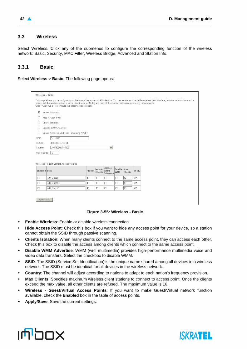
Figure 3-55: Wireless - Basic
Enable Wireless: Enable or disable wireless connection.
Hide Access Point: Check this box if you want to hide any access point for your device, so a stationcannot obtain the SSID through passive scanning.
Clients Isolation: When many clients connect to the same access point, they can access each other.Check this box to disable the access among clients which connect to the same access point.
Disable WMM Advertise: WMM (wi-fi multimedia) provides high-performance multimedia voice andvideo data transfers. Select the checkbox to disable WMM.
SSID: The SSID (Service Set Identification) is the unique name shared among all devices in a wirelessnetwork. The SSID must be identical for all devices in the wireless network.
Country: The channel will adjust according to nations to adapt to each nation's frequency provision.
Max Clients: Specifies maximum wireless client stations to connect to access point. Once the clientsexceed the max value, all other clients are refused. The maximum value is 16.
Wireless - Guest/Virtual Access Points: If you want to make Guest/Virtual network functionavailable, check the Enabled box in the table of access points.
Apply/Save: Save the current settings.

Security 43
3.3.2 Security
You can configure security features of the wireless LAN interface in this page.
1. Select Wireless > Security. The Wireless--Security page opens.
Figure 3-56: Wireless Security Configuration
You may setup security configuration manually or through Wi-Fi Protected Setup (WPS).
Note: Using WEP network authentication is not recommended because it does not offerreliable security. It should be used only when connecting older wireless clients that havecompatibility issues with other network authentication methods.
D. Management guide44
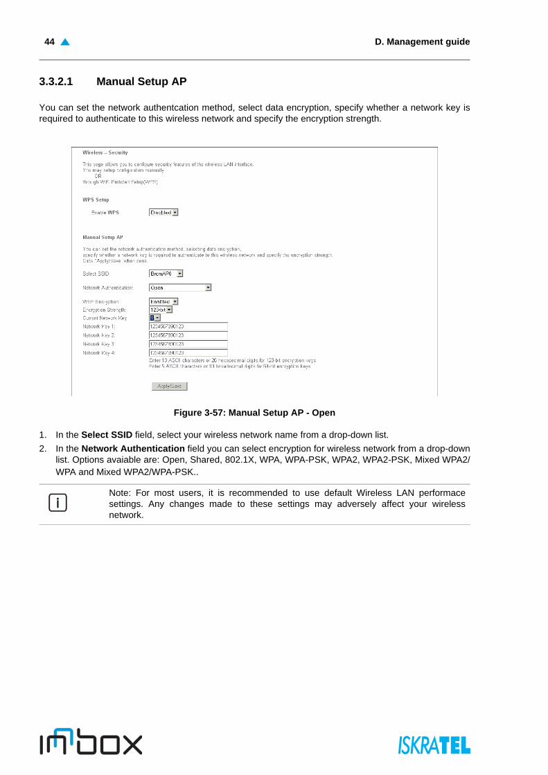
3.3.2.1 Manual Setup AP
You can set the network authentcation method, select data encryption, specify whether a network key isrequired to authenticate to this wireless network and specify the encryption strength.
Figure 3-57: Manual Setup AP - Open
1. In the Select SSID field, select your wireless network name from a drop-down list.
2. In the Network Authentication field you can select encryption for wireless network from a drop-downlist. Options avaiable are: Open, Shared, 802.1X, WPA, WPA-PSK, WPA2, WPA2-PSK, Mixed WPA2/WPA and Mixed WPA2/WPA-PSK..
Note: For most users, it is recommended to use default Wireless LAN performacesettings. Any changes made to these settings may adversely affect your wirelessnetwork.

WEP 45
3.3.2.1.1 WEP
WEP is a basic encryption method offering two levels of encryption, 64-bit and 128-bit encryption. Toconfigure the WEP encryption, there are three ways:
Keep the Network Authentication of Open and select Enable from the WEP Encryption drop-down list(shown in 3-57). Open allows any wireless station to associate with the access point.
Select Shared from the Network authentication drop-down list as shown in 3-58. Shared only allowsstations using a shared key encryption to associate with it. Shared key requires additionalconfiguration of the key to be used.
Select 802.1X from the Network authentication drop-down list as shown in 3-59. 802.1X allowing auser to be authenticated by a central authority.
Figure 3-58: Manual Setup AP - Shared
Encryption Strenght: Select the appropiate level of encryption, 64-bit or 128-bit.
Current Network Key: To indicate which WEP key to use, select a transmission key number.
Network Key 1-4: If you want to manually enter the WEP keys, then enter the network key in theNetwork Key 1-4 fields.
Apply/Save: Save the current settings.
D. Management guide46
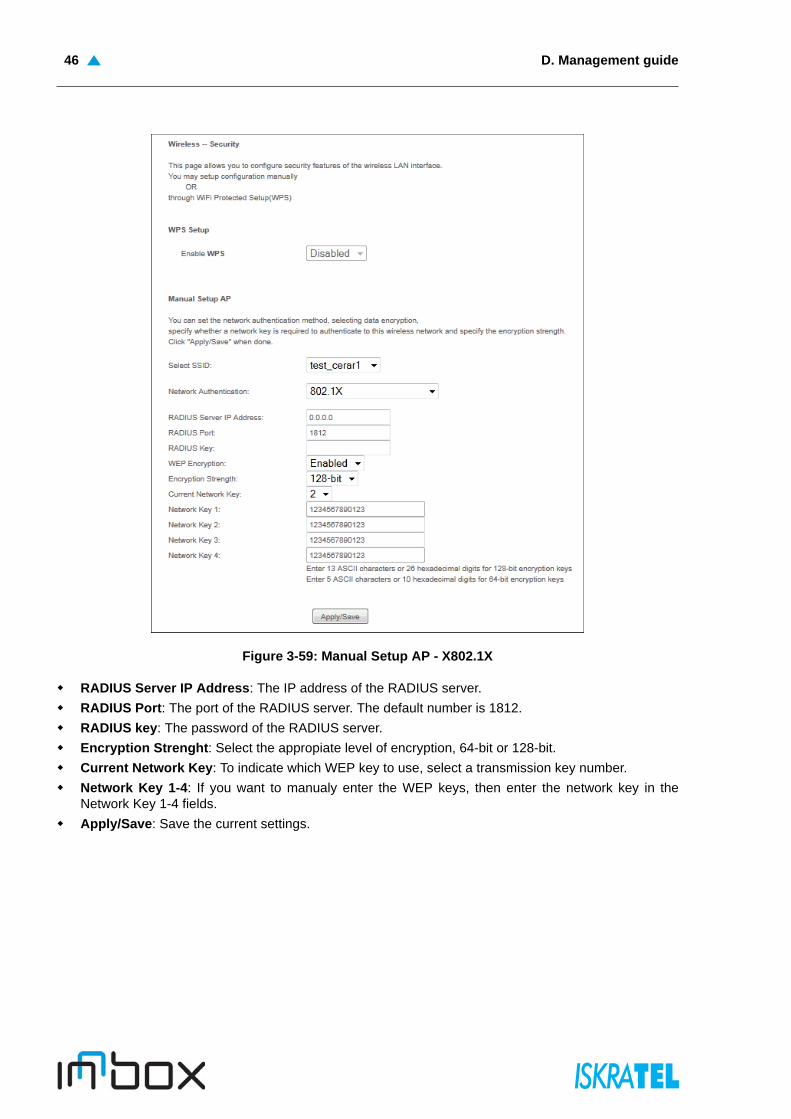
Figure 3-59: Manual Setup AP - X802.1X
RADIUS Server IP Address: The IP address of the RADIUS server.
RADIUS Port: The port of the RADIUS server. The default number is 1812.
RADIUS key: The password of the RADIUS server.
Encryption Strenght: Select the appropiate level of encryption, 64-bit or 128-bit.
Current Network Key: To indicate which WEP key to use, select a transmission key number.
Network Key 1-4: If you want to manualy enter the WEP keys, then enter the network key in theNetwork Key 1-4 fields.
Apply/Save: Save the current settings.

WPA 47
3.3.2.1.2 WPA
WPA security for wireless communication has been developed to overcome some of the shortcomings ofWEP. WPA combines generation with the authentication services of a RADIUS server.
Figure 3-60: Manual Setup AP - WPA
WPA Group ReKey Interval: Enter the Key Renewal period, which tells the home gateway how oftenit should change encryption keys.
RADIUS Server IP Address: The IP address of the RADIUS server.
RADIUS Port: The port of the RADIUS server. The default number is 1812.
RADIUS key: The password of the RADIUS server.
WPA/WAPI Encryption: Select the encryption you want to use: AES or TPIK+AES.
Apply/Save: Save the current settings.
D. Management guide48
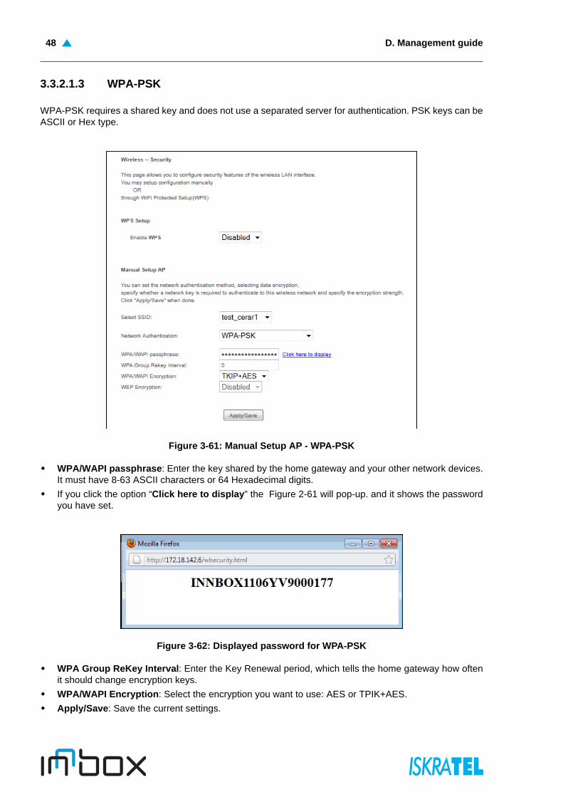
3.3.2.1.3 WPA-PSK
WPA-PSK requires a shared key and does not use a separated server for authentication. PSK keys can beASCII or Hex type.
Figure 3-61: Manual Setup AP - WPA-PSK
WPA/WAPI passphrase: Enter the key shared by the home gateway and your other network devices.It must have 8-63 ASCII characters or 64 Hexadecimal digits.
If you click the option “Click here to display” the Figure 2-61 will pop-up. and it shows the passwordyou have set.
Figure 3-62: Displayed password for WPA-PSK
WPA Group ReKey Interval: Enter the Key Renewal period, which tells the home gateway how oftenit should change encryption keys.
WPA/WAPI Encryption: Select the encryption you want to use: AES or TPIK+AES.
Apply/Save: Save the current settings.
WPA2 49
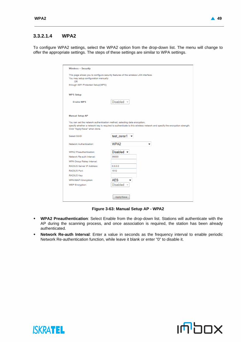
3.3.2.1.4 WPA2
To configure WPA2 settings, select the WPA2 option from the drop-down list. The menu will change tooffer the appropriate settings. The steps of these settings are similar to WPA settings.
Figure 3-63: Manual Setup AP - WPA2
WPA2 Preauthentication: Select Enable from the drop-down list. Stations will authenticate with theAP during the scanning process, and once association is required, the station has been alreadyauthenticated.
Network Re-auth Interval: Enter a value in seconds as the frequency interval to enable periodicNetwork Re-authentication function, while leave it blank or enter ”0” to disable it.

D. Management guide50
3.3.2.1.5 WPA2-PSK
To configure WPA2-PSK settings, select the WPA2-PSK option from the drop-down list. The menu willchange to offer the appropriate settings. WPA2-PSK requires a shared key and does not use a separatedserver for authentication. PSK keys can be ASCII or Hex type.
Figure 3-64: Manual Setup AP - WPA2-PSK

Mixed WPA2/WPA 51
3.3.2.1.6 Mixed WPA2/WPA
To configure Mixed WPA2/WPA settings, select the WPA2/WPA option from the drop-down list. The menuwill change to offer the appropriate settings. The steps to these settings are similar to those for WPA-PSK.
Figure 3-65: Manual Setup AP - WPA2/WPA
D. Management guide52
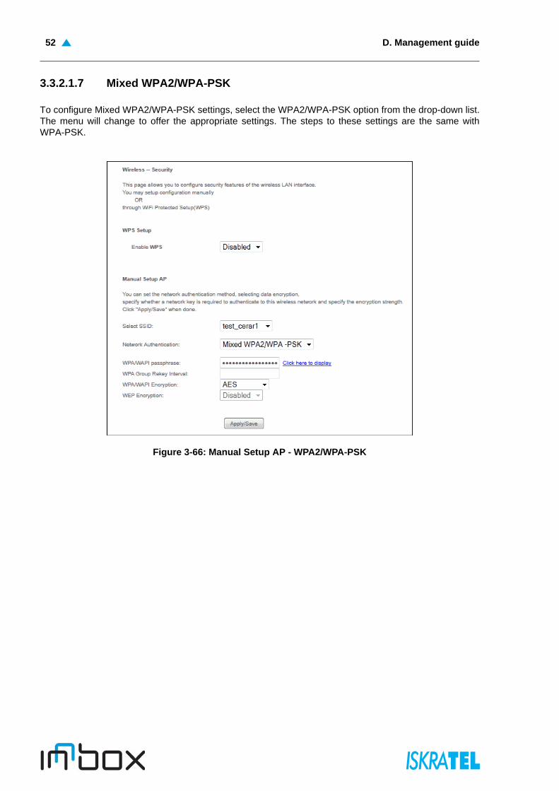
3.3.2.1.7 Mixed WPA2/WPA-PSK
To configure Mixed WPA2/WPA-PSK settings, select the WPA2/WPA-PSK option from the drop-down list.The menu will change to offer the appropriate settings. The steps to these settings are the same withWPA-PSK.
Figure 3-66: Manual Setup AP - WPA2/WPA-PSK

WPS Setup 53
3.3.2.2 WPS Setup
Wi-Fi protected setup (WPS) is a standard for easy and secure establishment of a wireless home network.The goal of the standard is to simplify the process of configuring security on wireless networks.The InnboxV50-U home gateway supports two different ways of adding a device to the wireless network:
PIN Method - a PIN (Personal Identification Number) has to be read from either a sticker on the newwireless client device (STA) or a display, if there is one, and entered at the "representant" of theNetwork.
Push-Button Method - user simply has to push a button, either an actual or virtual one, on both theAP (or a Registrar of the Network) and the new wireless client device.
Figure 3-67: Wireless Security Configuration - WPS
• Enabled: Select this option to enable wireless bridge restriction. Enter the MAC address of theRemote Bridges. Only these remote bridges are granted access.
• Enabled (Scan): Select this option to enable wireless bridge restriction, and it will scan theenvironment for APs that exist around the device. Only those selected AP will be granted access.
Refresh: Click this button to update the remote bridges.
Apply/Save: Click this button to save the settings.

D. Management guide54
3.3.3 MAC Filter
The Wireless MAC Filter feature allows you to control which wireless-equipped PCs or devices may or maynot communicate on your wireless network depending on their MAC address. If you do not wish to filterusers by MAC Address, select Disabled.
Select Wireless > MAC Filter. The following page opens:
Figure 3-68: Wireless MAC Filter Configuration
Select SSID: Select your wireless network name from a drop-down list.
Disabled: Select this option to disable MAC Filter function.
Allow: Select this option to enable MAC Filter function.
Deny: Select this option to enable MAC Filter function.
Add: Click this button to add the MAC Address.
Remove: Select the MAC Address entry and click this button to remove it.
3.3.3.1 Wireless -- MAC Filter
Select Wireless > MAC Filter > Add. The following page opens:
Figure 3-69: Wireless MAC Filter - Add
MAC Address: Enter the MAC address.
Apply/Save: Click this button to add the MAC address to the MAC address filter.

Wireless Bridge 55
3.3.4 Wireless Bridge
The device can also be configured as a wireless bridge. The wireless bridge mode will turn the accesspoint into a wireless bridge. Wireless clients will not be able to connect to the access point in this mode.
Select Wireless > Wireless Bridge. The following page opens:
Figure 3-70: Wireless Bridge
AP Mode: Select the AP mode from the drop-down list:
• Access Point: Select this option to allow wireless stations including AP clients to access.
• Wireless Bridge: Or WDS (Wireless Distribution System). It bridges the wireless stations, also inbridge mode, to connect two or more remote LANs.
Bridge Restrict:
• Disabled: Select this option to disable wireless bridge restriction. Any wireless bridge will begranted access.
• Enabled: Select this option to enable wireless bridge restriction. Enter the MAC address of theRemote Bridges. Only these remote bridges are granted access.
• Enabled (Scan): Select this option to enable wireless bridge restriction, and it will scan theenvironment for APs that exist around the device. Only those selected AP will be granted access.
Refresh: Click this button to update the remote bridges.
Apply/Save: Click this button to save the settings.

D. Management guide56
3.3.5 Advanced
Select Wireless > Advanced. The following page opens:
Figure 3-71: Wireless Advanced
Band: Select the band.
Channel: Select the channel you want to use from the drop-down list. This field determines whichoperating frequency will be used. It is not necessary to change the wireless channel unless you noticeinterference problems with another nearby access point.
Auto Channel Timer (min): Auto channel scan timer in minutes (0 to disable).
802.11n/EWC:
Bandwidth: Select the bandwidth from the drop-down list. When higher bandwidth is selected, thedevice could transmit and receive data with a higher speed.
Control Sideband: When higher bandwidth is selected, you can then select the Control Sideband youwant.
54g Rate (Wireless Communication Rate): Drop-down menu that specifies the following fixed rates:Auto: Default. Uses the 11 Mbps data rate when possible but drops to lower rates when necessary. 1Mbps, 2Mbps, 5.5Mbps, or 11Mbps fixed rates. The appropriate setting is dependent on signalstrength.
Multicast Rate: Multicast packet transmit rate.
Basic Rate: Basic transmit rate.
Fragmentation Threshold: A threshold, specified in bytes, that determines whether packets will befragmented and at what size. On an 802.11 WLAN, packets that exceed the fragmentation thresholdare fragmented, i.e., split into, smaller units suitable for the circuit size. Packets smaller than thespecified fragmentation threshold value are not fragmented. Enter a value between 256 and 2346. Ifyou experience a high packet error rate, try to slightly increase your Fragmentation Threshold. Thevalue should remain at its default setting of 2346. Setting the Fragmentation Threshold too low mayresult in poor performance.

Station info 57
RTS Threshold: When set in bytes, specifies the packet size beyond which the WLAN card invokes itsRTS/CTS mechanism. Packets that exceed the specified RTS threshold trigger the RTS/CTSmechanism. The NIC transmits smaller packet without using RTS/CTS. The default setting of 2347(maximum length) disables RTS threshold.
DTIM Interval: This value, between 1 and 255, indicates the interval of the Delivery Traffic IndicationMessage (DTIM). A DTIM field is a countdown field informing clients of the next window for listening tobroadcast and multicast messages. When the device has buffered broadcast or multicast messagesfor associated clients, it sends the next DTIM with a DTIM Interval value. Its clients hear the beaconsand awaken to receive the broadcast and multicast messages. The default value is 1.
Beacon Interval: Enter a value between 20-1000 milliseconds. The Beacon Interval value indicatesthe frequency interval of the beacon. A beacon is a packet broadcast by the device to synchronize thewireless network. The default value is 100.
Global Max Clients
XPress Technology: enabled or disabled.
Transmit Power: This option will allow you to configure the wireless transmit power. High transmitpower will extend the wireless signal range of the device and make the signal transmit more legible.Low transmit power with the smaller wireless signal range that will decrease the probability of interruptby other Wi-Fi device.
WMM (Wi-Fi Multimedia): This function can guarantee the packets with high-priority messages beingtransmitted preferentially.
WMM No Acknowledgement: Refers to the acknowledge policy used at the MAC level. Enabling noacknowledgement can result in more efficient throughput but higher error rates in a noisy RadioFrequency (RF) environment.
WMM APSD: Automatic Power Save Delivery. It saves power.
3.3.6 Station info
You can view the authenticated wireless stations and their status in this page.
Select Wireless > Station info. The following page opens:
Figure 3-72: Wireless Authenticated Stations
MAC: Displays the connected wireless station MAC address.
Associated: Displays whether the wireless station has associated with the access point.
Authorized: Displays the information of Authentication.
SSID: Displays the connected wireless station SSID.
Interface: Displays the connected wireless station Interface mode

D. Management guide58
3.4 Voice
This chapter describes the various options for configuration of the SIP voice service. Session InitiationProtocol (SIP) is a peer-to-peer protocol used for Internet conferencing, telephony, events notification,presence and instant messaging.
SIP is designed to address the functions of signalling and session management within a packet telephonynetwork. Signalling allows callinformation to be carried across network boundaries. Session managementprovides the ability to control the attributes of an end-to-end call.
You can configure the voice-related parameter:
SIP Basic Settings
SIP Advanced Settings
SIP Debug Settings
3.4.1 SIP Basic Settings
Select Voice > SIP Basic Settings. The following page opens:
Figure 3-73: SIP basic settings - Global parameters tab
Bound Interface Name: Select Bound Interface Name that will be used by the Voice-IAD system tofind the SIP Proxy server from drop-down list.
Start SIP client: Click to start the SIP client.
Stop SIP client: Click to stop the SIP client.
Restore default setting: Click to restore the default settings.
Apply: Click to confirm the setting.
SIP Basic Settings 59
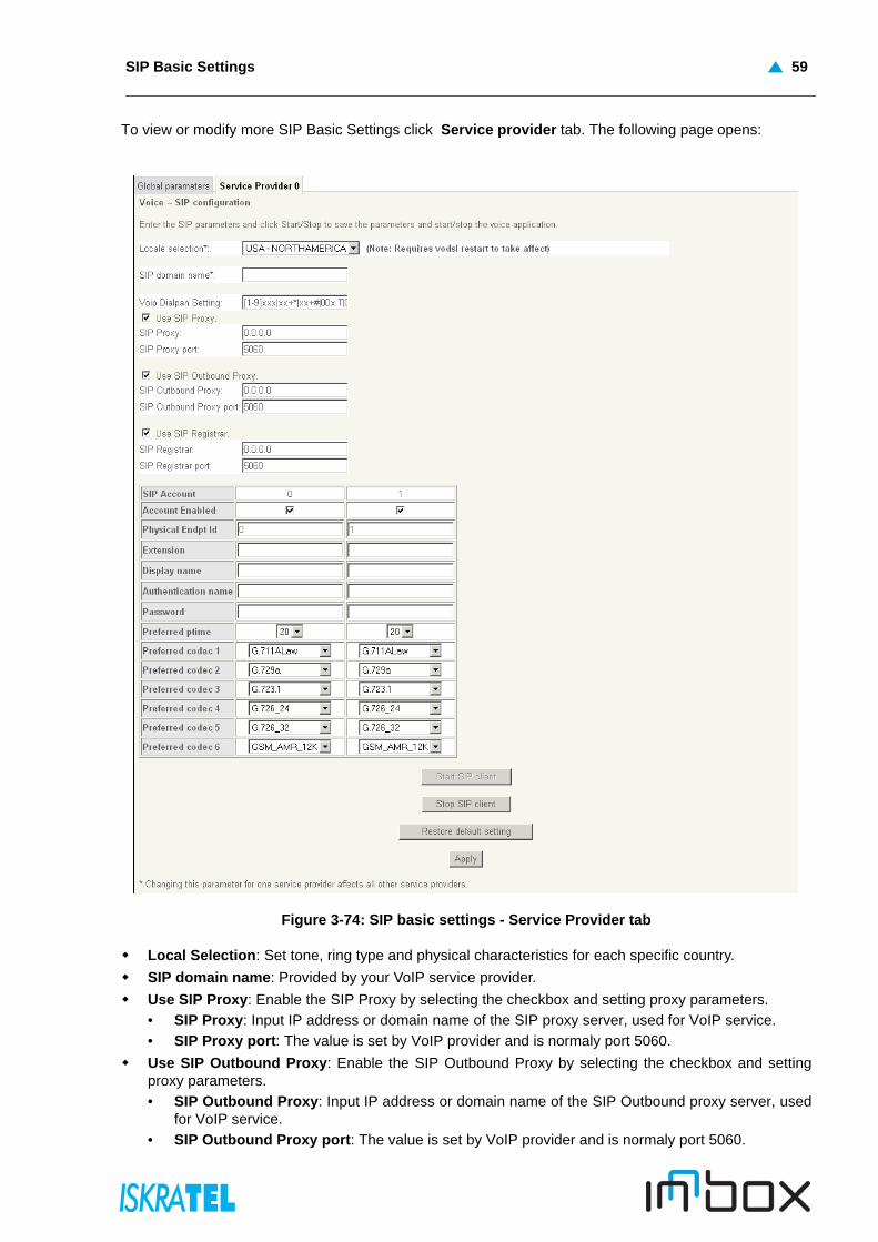
To view or modify more SIP Basic Settings click Service provider tab. The following page opens:
Figure 3-74: SIP basic settings - Service Provider tab
Local Selection: Set tone, ring type and physical characteristics for each specific country.
SIP domain name: Provided by your VoIP service provider.
Use SIP Proxy: Enable the SIP Proxy by selecting the checkbox and setting proxy parameters.
• SIP Proxy: Input IP address or domain name of the SIP proxy server, used for VoIP service.
• SIP Proxy port: The value is set by VoIP provider and is normaly port 5060.
Use SIP Outbound Proxy: Enable the SIP Outbound Proxy by selecting the checkbox and settingproxy parameters.
• SIP Outbound Proxy: Input IP address or domain name of the SIP Outbound proxy server, usedfor VoIP service.
• SIP Outbound Proxy port: The value is set by VoIP provider and is normaly port 5060.

D. Management guide60
Use SIP Registrar: Enable the SIP Registrar by selecting the checkbox and setting registrarparameters.
• SIP Registrar: Input IP address or domain name of the registrar server.
• SIP Registrar port: The value is set by VoIP provider and is normaly port 5060.
SIP Account: Ports TEL1 and TEL2.
Account Enabled: Account is enabled by selecting the checkbox.
Extension: The line extension number.
Display name: The string for called party’s telephone to display the caller name.
Authentication name: The authentication username for the Registrar/proxy, given by VoIP provider.
Password: The authentication password for the Registrar/proxy, given by VoIP provider.
Preferred ptime: The time period used to digitally sample the analog voice signal. The default is 20.
Preferred codec 1-6: Select preferd codec from drop-down list.
Start SIP client: Click to start the SIP client.
Stop SIP client: Click to stop the SIP client.
Restore default setting: Click to restore the default settings.
Apply: Click to confirm the setting.
3.4.2 SIP Advanced Settings
Select Voice > SIP Advanced Settings. The following page opens:
Figure 3-75: SIP advanced settings - Global parameters tab
Incoming PSTN Call Routing: From drop-down list you can select the following rules:
• Auto - PSTN call switch to idle line• Line - PSTN call switch to physical line• VoIP - PSTN call switch to voip call
Start SIP client: Click to start the SIP client.
Stop SIP client: Click to stop the SIP client.
Apply: Click to confirm the setting.

SIP Advanced Settings 61
For view or modify more SIP Advanced Settings click Service provider tab. The following page opens:
Figure 3-76: SIP advanced settings - Service Provider tab
Line: Ports TEL1 and TEL2.
Call waiting: Select the checkbox to enable this option.
Call forwarding number: Enter the forwarding phone number.
Forward unconditionally: Select the checkbox to enable this option.
Forward on “busy”: Select the checkbox to enable this option.
Forward on “no answer”: Select the checkbox to enable this option.
MWI: Enable or disable Message-Waiting Indicator (MWI) for FXS Phones with this checkbox.
Call barring: Select the checkbox to enable this option.
Call barring pin: Enter the call barring pin.
Call barring digit map: Enter the call barring digit map.
Anonymous call blocking: Select the checkbox to enable this option.
Anonymous calling: Select the checkbox to enable this option.
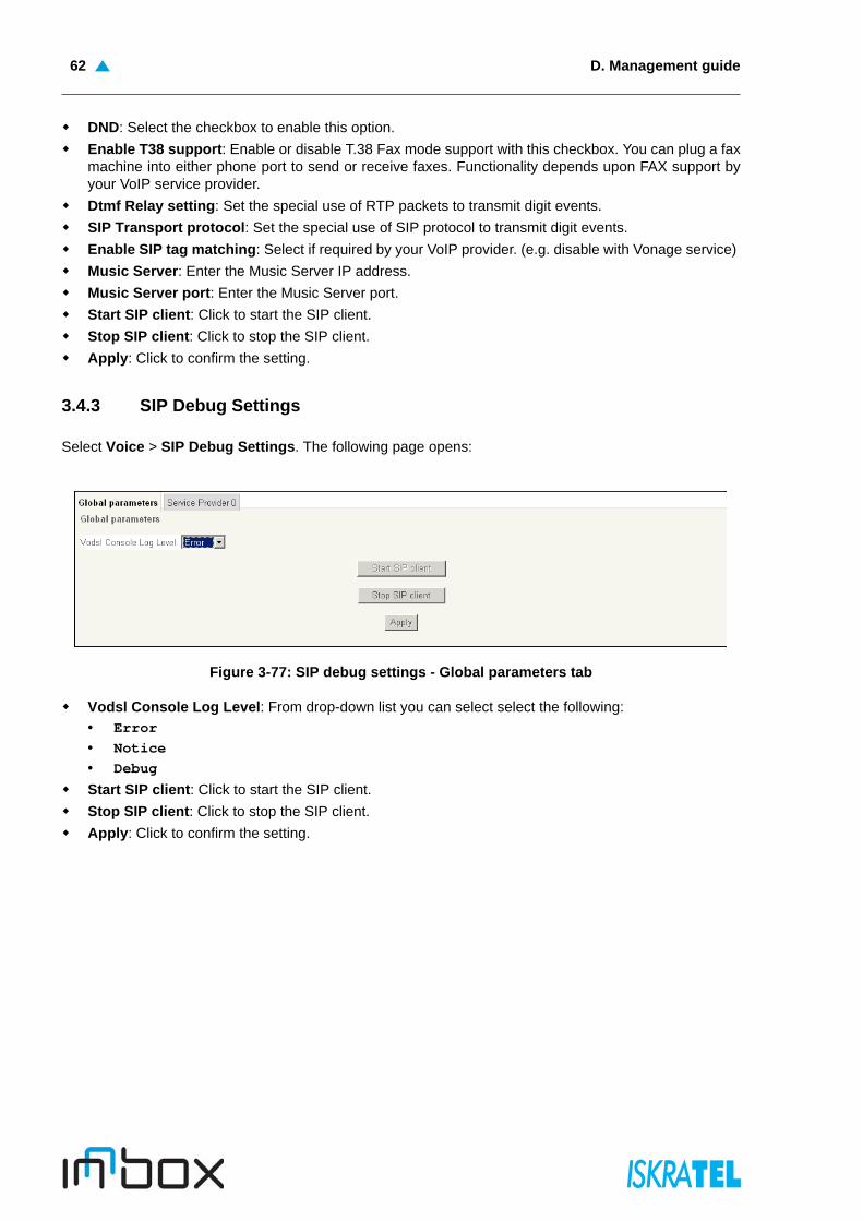
D. Management guide62
DND: Select the checkbox to enable this option.
Enable T38 support: Enable or disable T.38 Fax mode support with this checkbox. You can plug a faxmachine into either phone port to send or receive faxes. Functionality depends upon FAX support byyour VoIP service provider.
Dtmf Relay setting: Set the special use of RTP packets to transmit digit events.
SIP Transport protocol: Set the special use of SIP protocol to transmit digit events.
Enable SIP tag matching: Select if required by your VoIP provider. (e.g. disable with Vonage service)
Music Server: Enter the Music Server IP address.
Music Server port: Enter the Music Server port.
Start SIP client: Click to start the SIP client.
Stop SIP client: Click to stop the SIP client.
Apply: Click to confirm the setting.
3.4.3 SIP Debug Settings
Select Voice > SIP Debug Settings. The following page opens:
Figure 3-77: SIP debug settings - Global parameters tab
Vodsl Console Log Level: From drop-down list you can select select the following:
• Error• Notice• Debug
Start SIP client: Click to start the SIP client.
Stop SIP client: Click to stop the SIP client.
Apply: Click to confirm the setting.
Diagnostics 63
For view or modify more SIP Debug Settings click Service provider tab. The following page opens:
Figure 3-78: SIP debug settings- Service Provider tab
SIP log server IP Address: Input IP address of the SIP log server.
SIP log server port: Port number of the SIP log server.
Start SIP client: Click to start the SIP client.
Stop SIP client: Click to stop the SIP client.
Apply: Click to confirm the setting.
3.5 Diagnostics
3.5.1 Diagnostics
This section describes the result of the test for the connection to your local network, DSL service providerand Internet service provider. You can refer to the Help menu to get more information about thecorresponding test.
Figure 3-79: Diagnostics
D. Management guide64
Ethernet Connection
• Pass: indicates that the Ethernet interface from your computer is connected to the LAN port ofyour device. A flashing or solid green LAN LED on the device also signifies that an Ethernetconnection is present and that this test is successful.
• Fail: Indicates that the device does not detect the Ethernet interface on your computer.
USB Connection
• Pass: Indicates that the USB interface from your computer is connected to device properly.
• Down: Indicates that the device does not detect the signal from USB interface.
Wireless Connection
• Pass: Indicates that the Wireless interface from your computer is connected to the wirelessnetwork.
• Down: Indicates that the device does not detect the wireless network.
DSL Synchronization
• Pass: Indicates that the device has detected an DSL signal from the telephone company. A solidWAN LED on the device also indicates the detection of an DSL signal from the telephonecompany.
• Fail: Indicates that the device does not detect a signal from the telephone company’s DSLnetwork. The WAN LED will continue to flash green.
3.6 Management
3.6.1 Settings - Backup
You can save the current configuration of your device to a file on your computer. This is highlyrecommended before you change any configuration settings or before you upgrade the firmware.
Select Management > Settings > Backup. The following page opens:
Figure 3-80: Backup Settings
Backup Settings: Click this button to save the device configurations to a file on your PC.
Update settings 65
3.6.2 Update settings
You can update the current configuration of your device from your saved files.
Select Management > Settings > Update. The following page opens:
Figure 3-81: Update Settings
Settings File Name: Enter the path to the settings file.
Browse: Click this button to locate the settings file name.
Update Settings: Click this button to update your device settings.
3.6.3 Restore Default settings
You can restore the current configuration of your device to the factory defaults.
Select Management > Settings > Restore Default. The following page opens:
Figure 3-82: Restore Default Settings
Restore Default Settings: Click this button to restore your device configurations to the factorydefaults.
Figure 3-83: Broadband Router Restore
Close the window and wait for 2 minutes before reopening your web browser. If necessary, reconfigureyour PC IP address to match your new configuration.
D. Management guide66
3.6.4 System Log
You can view and configure the system log options in the System Log page.
Select Management > System Log. The following page opens:
Figure 3-84: System Log
View System Log: Click this button to view the system log.
Configure System Log: Click this button to configure the system log.
3.6.4.1 System Log Configuration
Select Management > Settings > System Log > Configure System Log. The following page opens:
Figure 3-85: Configure System Log
Disable/Enable: Select Enable to log the events, otherwise select Disable.
Log Level: Select the log level in the drop-down list. All events above or equal to the selected level willbe logged.
Display Level: Select the display level in the drop-down list. All logged events above or equal to theselected level will be displayed.
Mode: Select the mode to record the events. If the selected mode is Local, events will be recorded inthe local memory. If the selected mode is Remote, events will be sent to the specified IP address andUDP port of the remote system log server. If the selected mode is Both, events will be sent to the localmemory and the remote system log server.
Apply/Save: Click this button to save the system log settings.
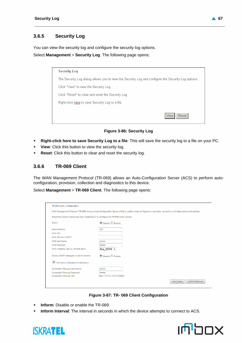
Security Log 67
3.6.5 Security Log
You can view the security log and configure the security log options.
Select Management > Security Log. The following page opens:
Figure 3-86: Security Log
Right-click here to save Security Log to a file: This will save the security log to a file on your PC.
View: Click this button to view the security log.
Reset: Click this button to clear and reset the security log.
3.6.6 TR-069 Client
The WAN Management Protocol (TR-069) allows an Auto-Configuration Server (ACS) to perform auto-configuration, provision, collection and diagnostics to this device.
Select Management > TR-069 Client. The following page opens:
Figure 3-87: TR- 069 Client Configuration
Inform: Disable or enable the TR-069.
Inform Interval: The interval in seconds in which the device attempts to connect to ACS.
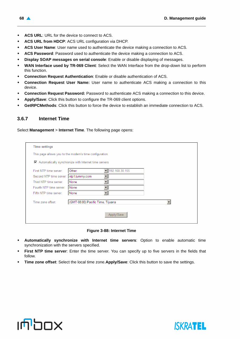
D. Management guide68
ACS URL: URL for the device to connect to ACS.
ACS URL from HDCP: ACS URL configuration via DHCP.
ACS User Name: User name used to authenticate the device making a connection to ACS.
ACS Password: Password used to authenticate the device making a connection to ACS.
Display SOAP messages on serial console: Enable or disable displaying of messages.
WAN Interface used by TR-069 Client: Select the WAN Interface from the drop-down list to performthis function.
Connection Request Authentication: Enable or disable authentication of ACS.
Connection Request User Name: User name to authenticate ACS making a connection to thisdevice.
Connection Request Password: Password to authenticate ACS making a connection to this device.
Apply/Save: Click this button to configure the TR-069 client options.
GetRPCMethods: Click this button to force the device to establish an immediate connection to ACS.
3.6.7 Internet Time
Select Management > Internet Time. The following page opens:
Figure 3-88: Internet Time
Automatically synchronize with Internet time servers: Option to enable automatic timesynchronization with the servers specified.
First NTP time server: Enter the time server. You can specify up to five servers in the fields thatfollow.
Time zone offset: Select the local time zone.Apply/Save: Click this button to save the settings.
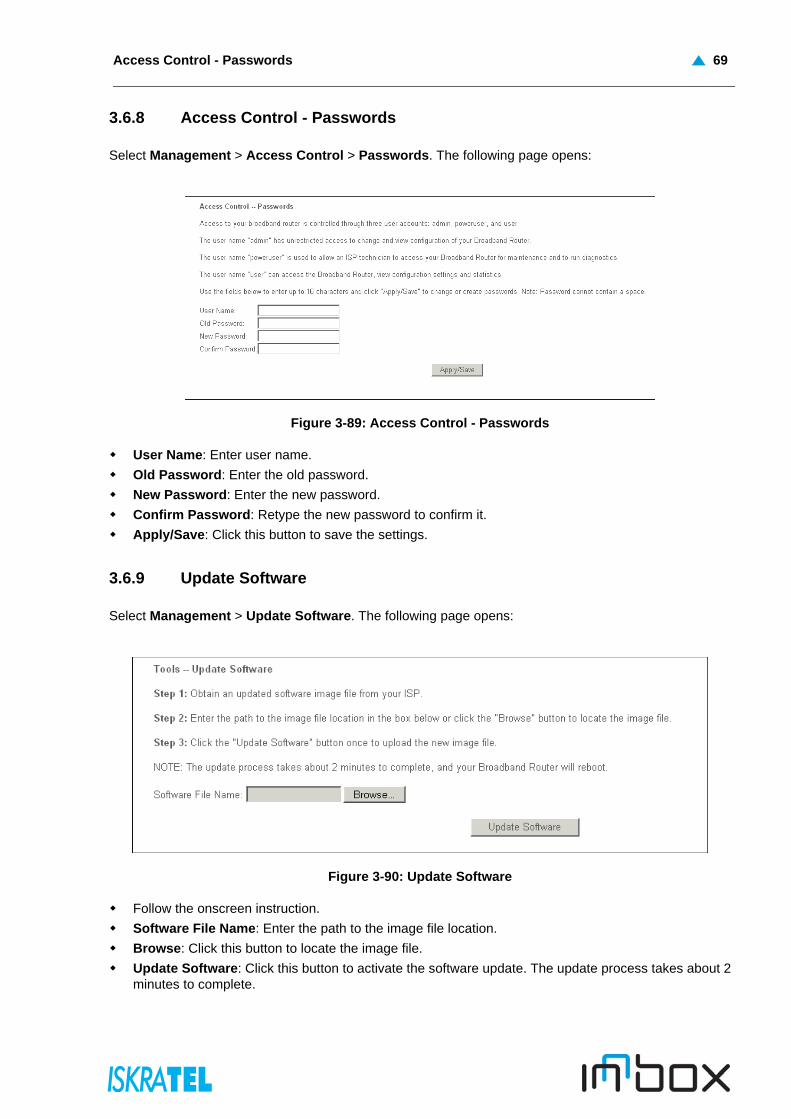
Access Control - Passwords 69
3.6.8 Access Control - Passwords
Select Management > Access Control > Passwords. The following page opens:
Figure 3-89: Access Control - Passwords
User Name: Enter user name.
Old Password: Enter the old password.
New Password: Enter the new password.
Confirm Password: Retype the new password to confirm it.
Apply/Save: Click this button to save the settings.
3.6.9 Update Software
Select Management > Update Software. The following page opens:
Figure 3-90: Update Software
Follow the onscreen instruction.
Software File Name: Enter the path to the image file location.
Browse: Click this button to locate the image file.
Update Software: Click this button to activate the software update. The update process takes about 2minutes to complete.
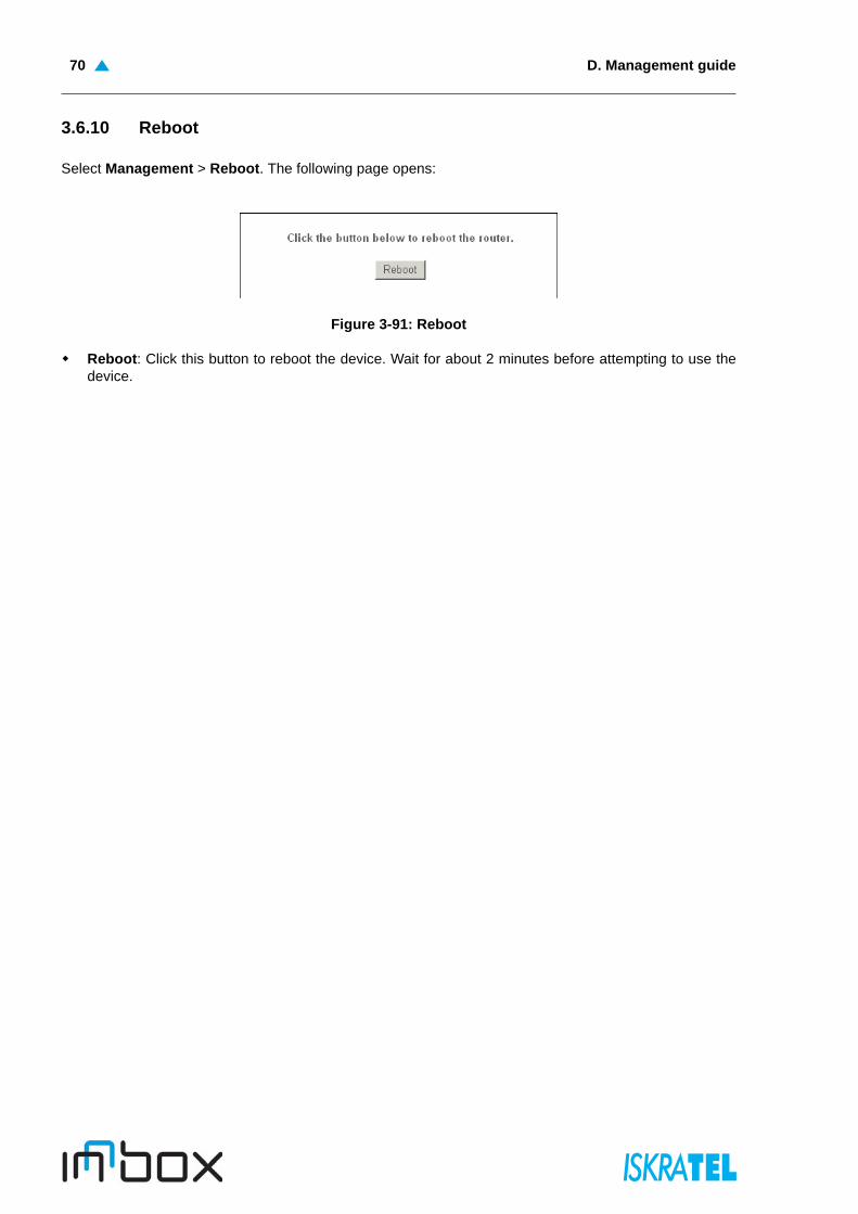
D. Management guide70
3.6.10 Reboot
Select Management > Reboot. The following page opens:
Figure 3-91: Reboot
Reboot: Click this button to reboot the device. Wait for about 2 minutes before attempting to use thedevice.