initial inspection: returns: charge-backs: legal action · charge-backs: we will do everything in...
TRANSCRIPT
Thank you for your purchase of your Xtreme Fat Tire Bike.
INITIAL INSPECTION:
Please inspect your packaging upon arrival for any damage that may have occurred in shipping.
If you see any damage take photographs, and call us immediately so we can file a claim if
necessary. Please do not remove the bike until we file a claim with FedEx.
RETURNS:
Please note: As per our policy on the website, returns must be made within 3 days of delivery
and are subject to a 20% restocking fee. You must call us at 757-635-5160 if you intend to return
the bike so we can issue a RMA (Return Material Authorization) number. Returns will not be
accepted any other way. After the 3-day period, all sales are final. Return shipping costs are the
responsibility of the buyer, unless the bike is damaged in shipping.
CHARGE-BACKS:
We will do everything in our power to honor the 1-year warranty on parts and ensure your
satisfaction with our products. If you have a defective part, you must return it to us before we can
send you a replacement part. A chargeback to your credit card company is not a method of
correcting a warranty issue as you already have your electric bike. We consider charge-backs as
a form of theft when you already have your merchandise and will prosecute them to the full
extent of the law and you will be responsible for all attorneys’ fees.
LEGAL ACTION:
Fatty AT E-Bikes is a limited liability corporation located in Deerfield Beach, FL. Any legal
action taken against the company, or its employees or owners must be in the jurisdiction of
Broward County, Florida.
ASSEMBLY:
When properly assembled and maintained your new bike will give you many years of riding
pleasure.
We highly recommend that all bikes are either assembled or checked by a trained
professional bicycle mechanic prior to riding. Bikes assembled improperly void the
warranty. If you are not confident in your ability to assemble the bike, please hire a
professional bicycle mechanic.
Xtreme Fat Tire Bikes, its owners, employees and affiliates are not liable in any way for any
accident, injury or death that may occur from an improperly assembled bicycle or improper use
of the bike.
In addition, riders should be fully aware of the unique capabilities of the Xtreme Fat Tire Bike
that allows them to ride in all types of terrain and in various conditions, and can pose additional
risks to the rider. Riders should use extreme caution to always ride within their skills and
refrain from riding in extreme conditions unless you are experienced with the particular riding
style and terrain which you are riding on. Just because your bike can handle a certain situation
doesn't mean the rider can. Always use good judgment, wear a properly fitted helmet and
protective riding gear, and always be alert to your surroundings. The instructions in this manual
are designed to provide a general guideline for the assembly of all models of Xtreme Fat Tire E-
Bikes. Please register your Xtreme Fat Tire Bike online using the Serial Number to ensure
warranty via our website: www.XtremeFatTireBikes.com.
By registering your electric bike you automatically activate your warranty. The only pieces of
information needed to complete the registration are the serial number (located directly under the
crank shaft), the model name, frame and wattage size. EXAMPLE: E-Grizzly 19" 1000 Watt
Your bike will be received with all of the necessary components needed for complete assembly.
Note, if for any reason your box arrives with damages to the exterior of the box, please take
photographs and document this possible shipping damage. If upon further inspection any
damage to the actual e-bike is found, please keep the box and contact us immediately at 757-635-
5160.
Your Signature:
Undersigned agrees to Xtreme Fat Tire Bikes Terms and Agreement:
Dated:
______________________________________________________________________________
TOOLS NEEDED FOR ASSEMBLY:
*Snips or scissors to cut zip-tie straps
*Allen wrenches: 5mm, 4mm and 3mm
*18mm wrench for front axle nuts
*Adjustable wrench to install the pedals (or pedal wrench)
REMOVAL FROM BIKE BOX AND SET-UP:
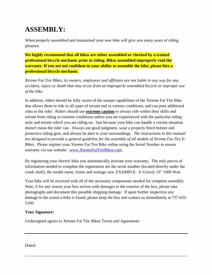
We are going to begin removing your e-bike from the box. Upon opening your box, you will
find the frame with the back wheel already assembled, the front wheel and front fork strapped to
the frame, a component box, a battery box, and your battery charger all inside of the box.
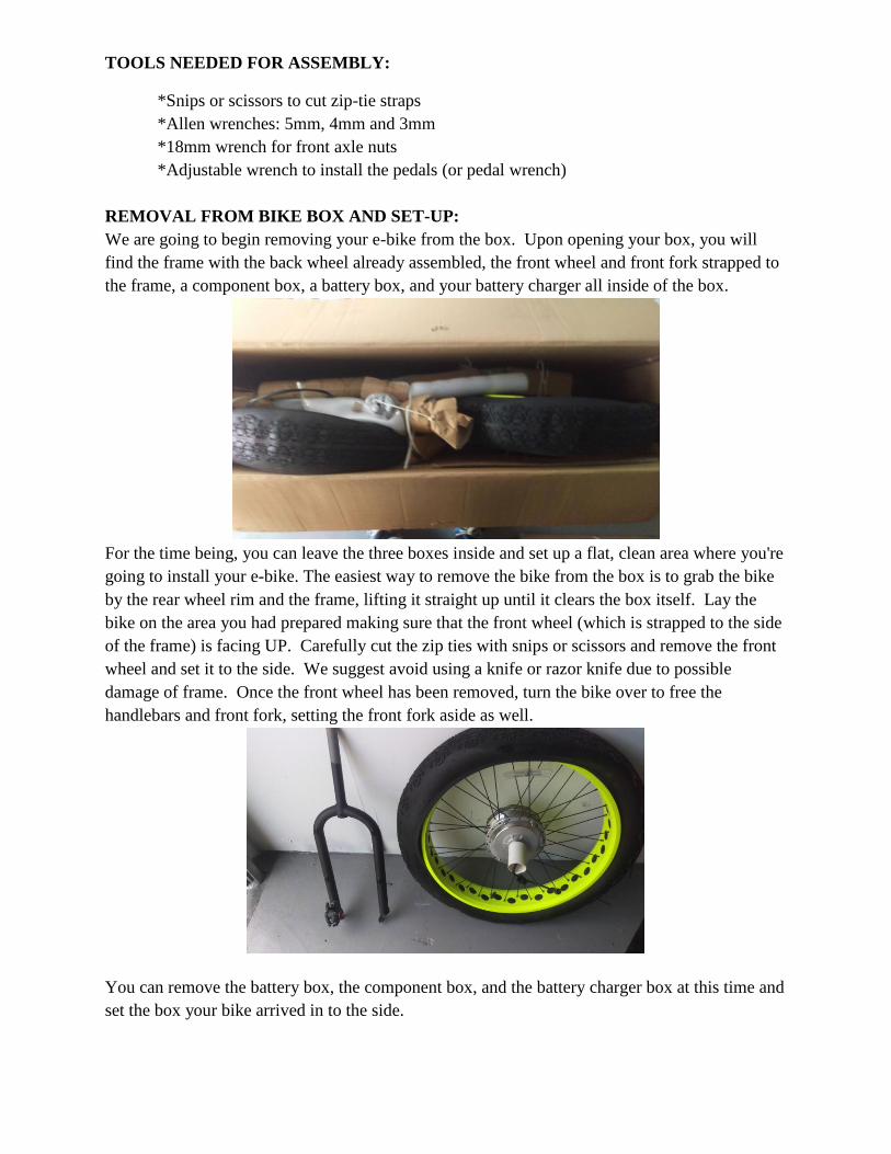
For the time being, you can leave the three boxes inside and set up a flat, clean area where you're
going to install your e-bike. The easiest way to remove the bike from the box is to grab the bike
by the rear wheel rim and the frame, lifting it straight up until it clears the box itself. Lay the
bike on the area you had prepared making sure that the front wheel (which is strapped to the side
of the frame) is facing UP. Carefully cut the zip ties with snips or scissors and remove the front
wheel and set it to the side. We suggest avoid using a knife or razor knife due to possible
damage of frame. Once the front wheel has been removed, turn the bike over to free the
handlebars and front fork, setting the front fork aside as well.
You can remove the battery box, the component box, and the battery charger box at this time and
set the box your bike arrived in to the side.
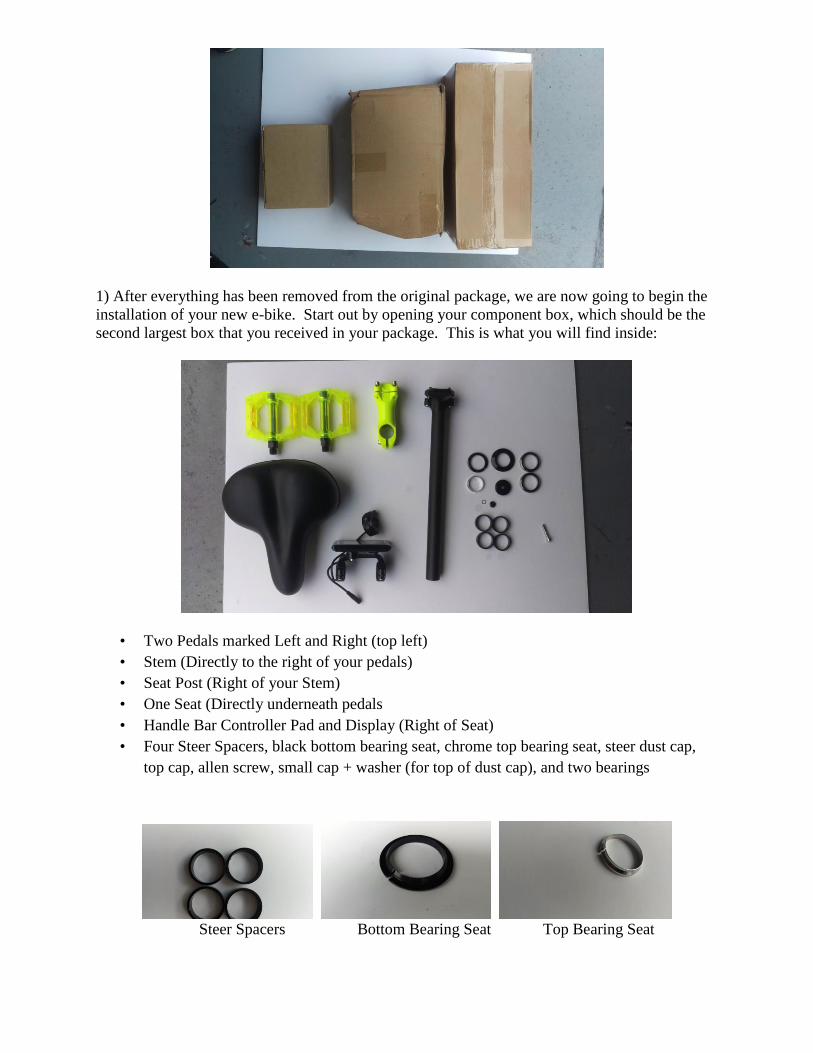
1) After everything has been removed from the original package, we are now going to begin the
installation of your new e-bike. Start out by opening your component box, which should be the
second largest box that you received in your package. This is what you will find inside:
• Two Pedals marked Left and Right (top left)
• Stem (Directly to the right of your pedals)
• Seat Post (Right of your Stem)
• One Seat (Directly underneath pedals
• Handle Bar Controller Pad and Display (Right of Seat)
• Four Steer Spacers, black bottom bearing seat, chrome top bearing seat, steer dust cap,
top cap, allen screw, small cap + washer (for top of dust cap), and two bearings
Steer Spacers Bottom Bearing Seat Top Bearing Seat
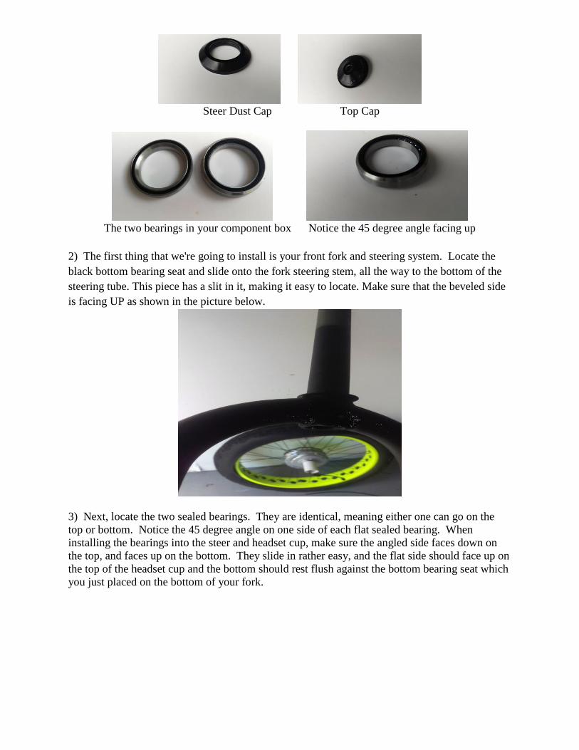
Steer Dust Cap Top Cap
The two bearings in your component box Notice the 45 degree angle facing up
2) The first thing that we're going to install is your front fork and steering system. Locate the
black bottom bearing seat and slide onto the fork steering stem, all the way to the bottom of the
steering tube. This piece has a slit in it, making it easy to locate. Make sure that the beveled side
is facing UP as shown in the picture below.
3) Next, locate the two sealed bearings. They are identical, meaning either one can go on the
top or bottom. Notice the 45 degree angle on one side of each flat sealed bearing. When
installing the bearings into the steer and headset cup, make sure the angled side faces down on
the top, and faces up on the bottom. They slide in rather easy, and the flat side should face up on
the top of the headset cup and the bottom should rest flush against the bottom bearing seat which
you just placed on the bottom of your fork.
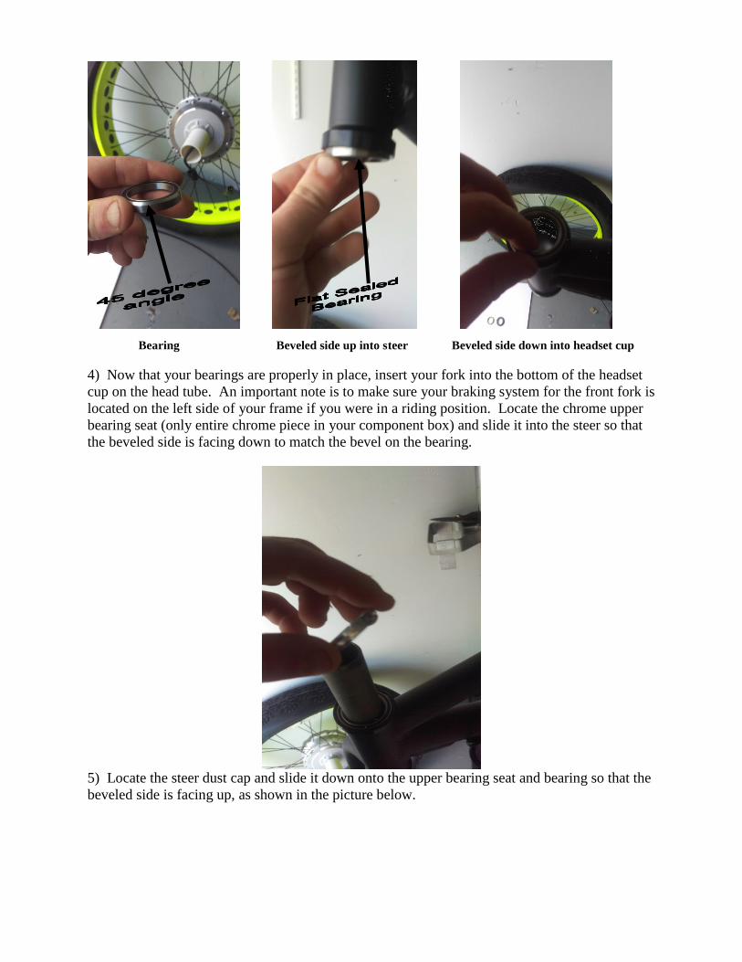
Bearing Beveled side up into steer Beveled side down into headset cup
4) Now that your bearings are properly in place, insert your fork into the bottom of the headset
cup on the head tube. An important note is to make sure your braking system for the front fork is
located on the left side of your frame if you were in a riding position. Locate the chrome upper
bearing seat (only entire chrome piece in your component box) and slide it into the steer so that
the beveled side is facing down to match the bevel on the bearing.
5) Locate the steer dust cap and slide it down onto the upper bearing seat and bearing so that the
beveled side is facing up, as shown in the picture below.
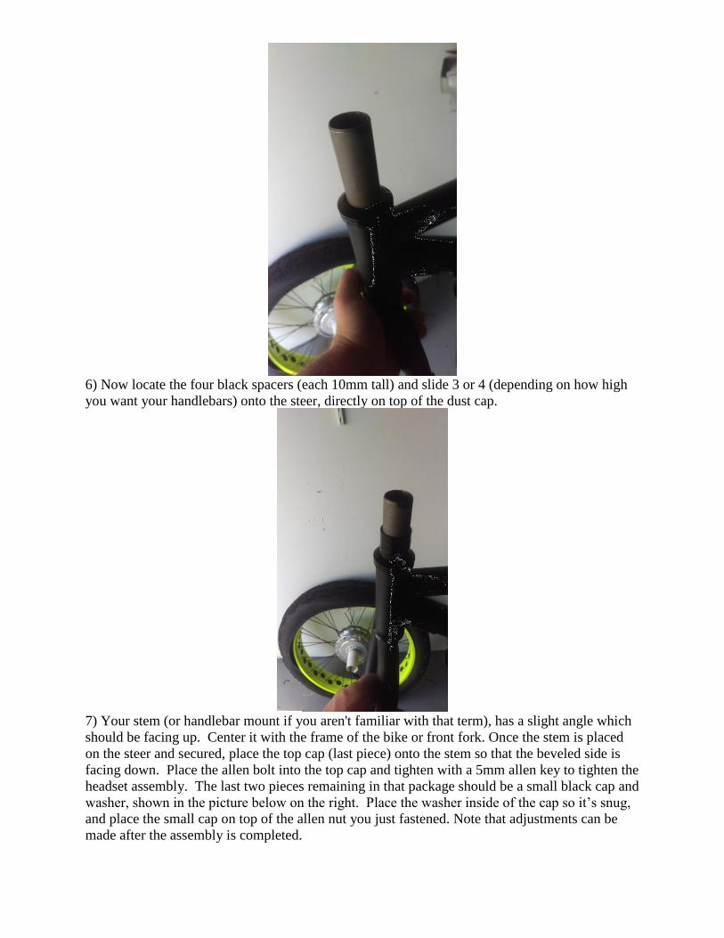
6) Now locate the four black spacers (each 10mm tall) and slide 3 or 4 (depending on how high
you want your handlebars) onto the steer, directly on top of the dust cap.
7) Your stem (or handlebar mount if you aren't familiar with that term), has a slight angle which
should be facing up. Center it with the frame of the bike or front fork. Once the stem is placed
on the steer and secured, place the top cap (last piece) onto the stem so that the beveled side is
facing down. Place the allen bolt into the top cap and tighten with a 5mm allen key to tighten the
headset assembly. The last two pieces remaining in that package should be a small black cap and
washer, shown in the picture below on the right. Place the washer inside of the cap so it’s snug,
and place the small cap on top of the allen nut you just fastened. Note that adjustments can be
made after the assembly is completed.
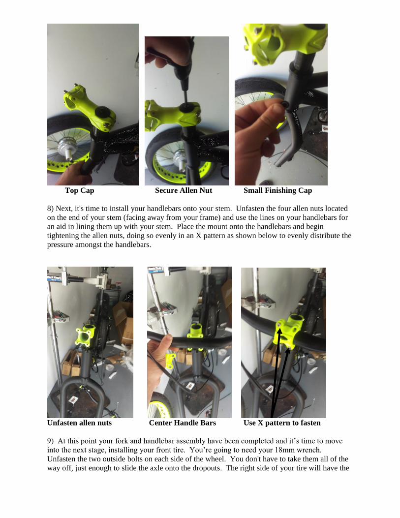
Top Cap Secure Allen Nut Small Finishing Cap
8) Next, it's time to install your handlebars onto your stem. Unfasten the four allen nuts located
on the end of your stem (facing away from your frame) and use the lines on your handlebars for
an aid in lining them up with your stem. Place the mount onto the handlebars and begin
tightening the allen nuts, doing so evenly in an X pattern as shown below to evenly distribute the
pressure amongst the handlebars.
Unfasten allen nuts Center Handle Bars Use X pattern to fasten
9) At this point your fork and handlebar assembly have been completed and it’s time to move
into the next stage, installing your front tire. You’re going to need your 18mm wrench.
Unfasten the two outside bolts on each side of the wheel. You don't have to take them all of the
way off, just enough to slide the axle onto the dropouts. The right side of your tire will have the
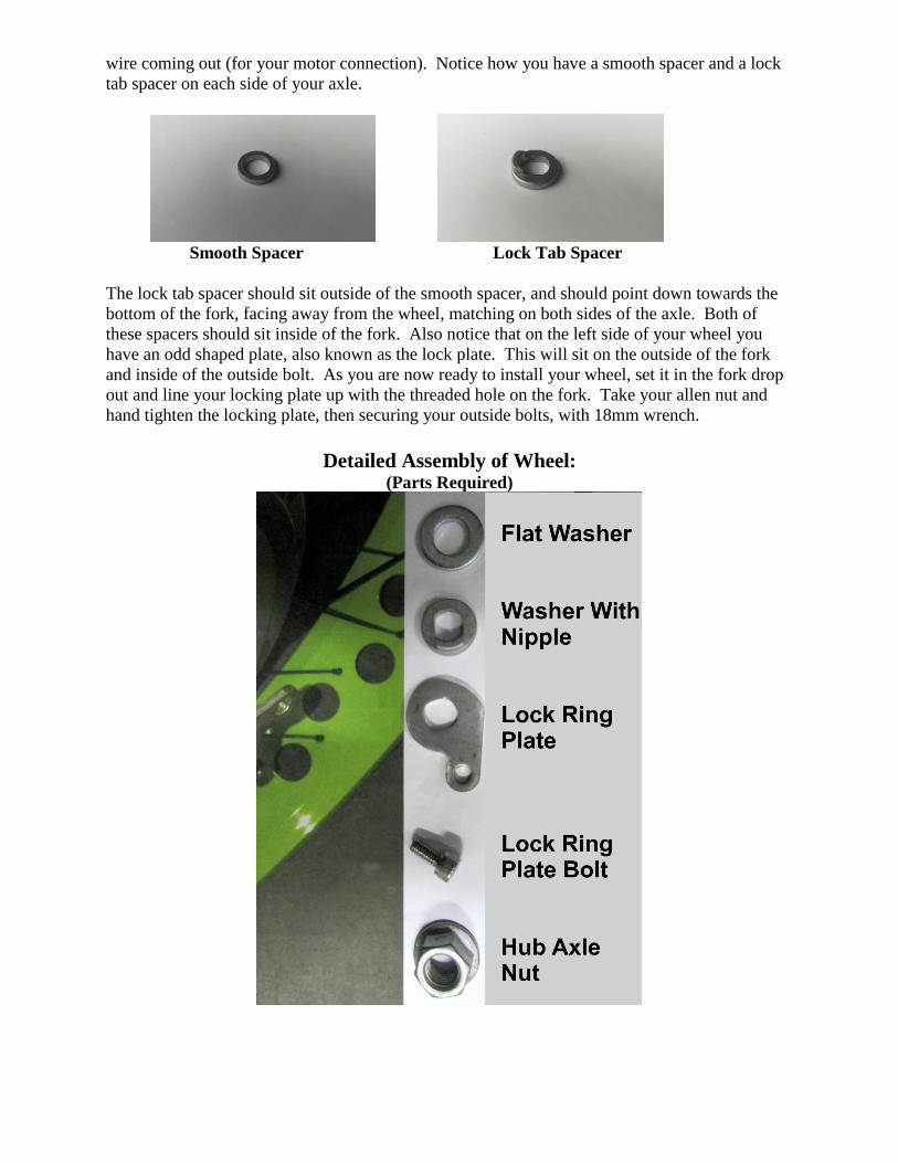
wire coming out (for your motor connection). Notice how you have a smooth spacer and a lock
tab spacer on each side of your axle.
Smooth Spacer Lock Tab Spacer
The lock tab spacer should sit outside of the smooth spacer, and should point down towards the
bottom of the fork, facing away from the wheel, matching on both sides of the axle. Both of
these spacers should sit inside of the fork. Also notice that on the left side of your wheel you
have an odd shaped plate, also known as the lock plate. This will sit on the outside of the fork
and inside of the outside bolt. As you are now ready to install your wheel, set it in the fork drop
out and line your locking plate up with the threaded hole on the fork. Take your allen nut and
hand tighten the locking plate, then securing your outside bolts, with 18mm wrench.
Detailed Assembly of Wheel: (Parts Required)
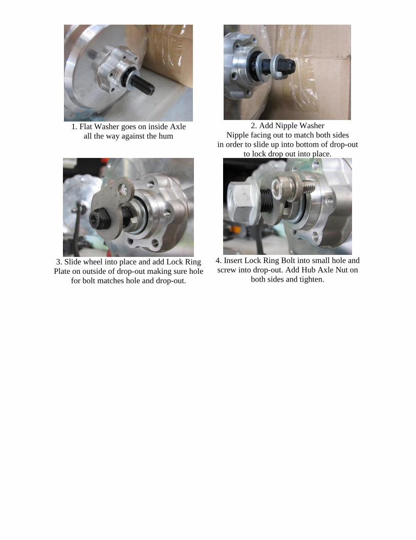
1. Flat Washer goes on inside Axle
all the way against the hum
2. Add Nipple Washer
Nipple facing out to match both sides
in order to slide up into bottom of drop-out
to lock drop out into place.
3. Slide wheel into place and add Lock Ring
Plate on outside of drop-out making sure hole
for bolt matches hole and drop-out.
4. Insert Lock Ring Bolt into small hole and
screw into drop-out. Add Hub Axle Nut on
both sides and tighten.
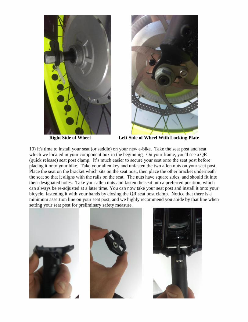
Right Side of Wheel Left Side of Wheel With Locking Plate
10) It's time to install your seat (or saddle) on your new e-bike. Take the seat post and seat
which we located in your component box in the beginning. On your frame, you'll see a QR
(quick release) seat post clamp. It’s much easier to secure your seat onto the seat post before
placing it onto your bike. Take your allen key and unfasten the two allen nuts on your seat post.
Place the seat on the bracket which sits on the seat post, then place the other bracket underneath
the seat so that it aligns with the rails on the seat. The nuts have square sides, and should fit into
their designated holes. Take your allen nuts and fasten the seat into a preferred position, which
can always be re-adjusted at a later time. You can now take your seat post and install it onto your
bicycle, fastening it with your hands by closing the QR seat post clamp. Notice that there is a
minimum assertion line on your seat post, and we highly recommend you abide by that line when
setting your seat post for preliminary safety measure.
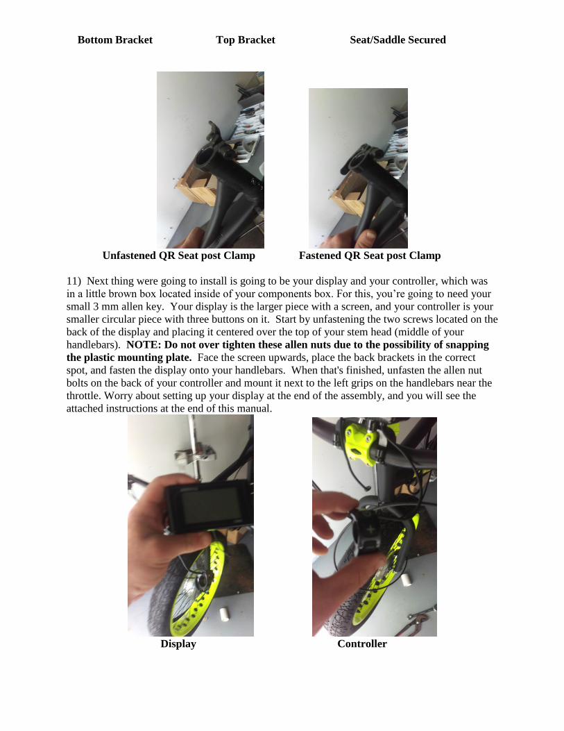
Bottom Bracket Top Bracket Seat/Saddle Secured
Unfastened QR Seat post Clamp Fastened QR Seat post Clamp
11) Next thing were going to install is going to be your display and your controller, which was
in a little brown box located inside of your components box. For this, you’re going to need your
small 3 mm allen key. Your display is the larger piece with a screen, and your controller is your
smaller circular piece with three buttons on it. Start by unfastening the two screws located on the
back of the display and placing it centered over the top of your stem head (middle of your
handlebars). NOTE: Do not over tighten these allen nuts due to the possibility of snapping
the plastic mounting plate. Face the screen upwards, place the back brackets in the correct
spot, and fasten the display onto your handlebars. When that's finished, unfasten the allen nut
bolts on the back of your controller and mount it next to the left grips on the handlebars near the
throttle. Worry about setting up your display at the end of the assembly, and you will see the
attached instructions at the end of this manual.
Display Controller
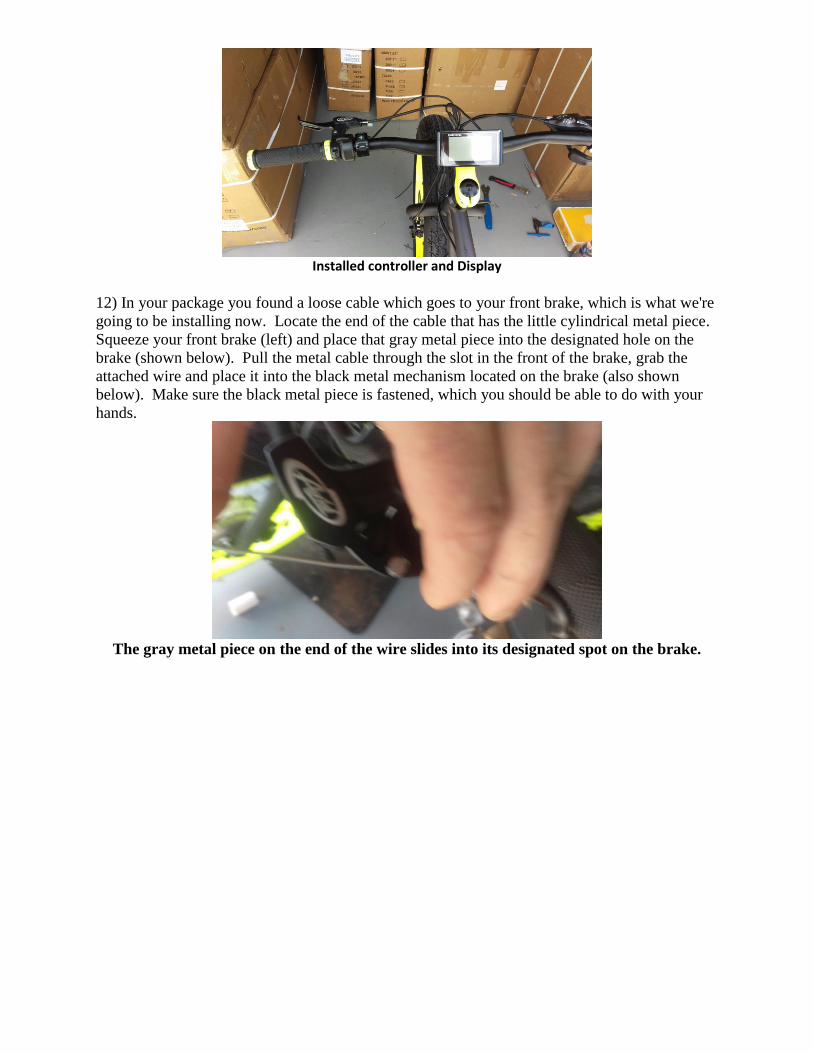
Installed controller and Display
12) In your package you found a loose cable which goes to your front brake, which is what we're
going to be installing now. Locate the end of the cable that has the little cylindrical metal piece.
Squeeze your front brake (left) and place that gray metal piece into the designated hole on the
brake (shown below). Pull the metal cable through the slot in the front of the brake, grab the
attached wire and place it into the black metal mechanism located on the brake (also shown
below). Make sure the black metal piece is fastened, which you should be able to do with your
hands.
The gray metal piece on the end of the wire slides into its designated spot on the brake.
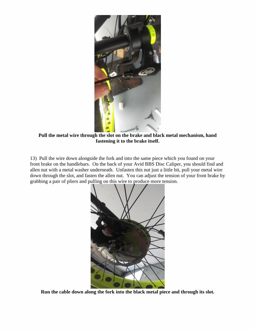
Pull the metal wire through the slot on the brake and black metal mechanism, hand
fastening it to the brake itself.
13) Pull the wire down alongside the fork and into the same piece which you found on your
front brake on the handlebars. On the back of your Avid BBS Disc Caliper, you should find and
allen nut with a metal washer underneath. Unfasten this nut just a little bit, pull your metal wire
down through the slot, and fasten the allen nut. You can adjust the tension of your front brake by
grabbing a pair of pliers and pulling on this wire to produce more tension.
Run the cable down along the fork into the black metal piece and through its slot.
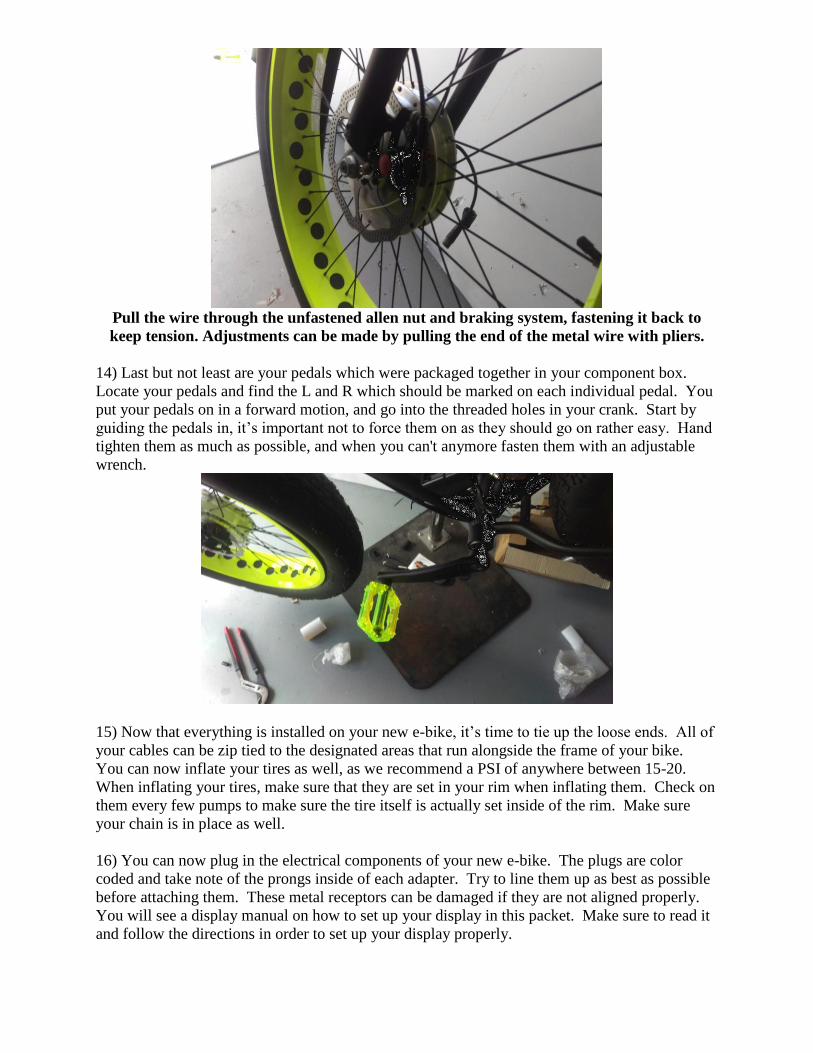
Pull the wire through the unfastened allen nut and braking system, fastening it back to
keep tension. Adjustments can be made by pulling the end of the metal wire with pliers.
14) Last but not least are your pedals which were packaged together in your component box.
Locate your pedals and find the L and R which should be marked on each individual pedal. You
put your pedals on in a forward motion, and go into the threaded holes in your crank. Start by
guiding the pedals in, it’s important not to force them on as they should go on rather easy. Hand
tighten them as much as possible, and when you can't anymore fasten them with an adjustable
wrench.
15) Now that everything is installed on your new e-bike, it’s time to tie up the loose ends. All of
your cables can be zip tied to the designated areas that run alongside the frame of your bike.
You can now inflate your tires as well, as we recommend a PSI of anywhere between 15-20.
When inflating your tires, make sure that they are set in your rim when inflating them. Check on
them every few pumps to make sure the tire itself is actually set inside of the rim. Make sure
your chain is in place as well.
16) You can now plug in the electrical components of your new e-bike. The plugs are color
coded and take note of the prongs inside of each adapter. Try to line them up as best as possible
before attaching them. These metal receptors can be damaged if they are not aligned properly.
You will see a display manual on how to set up your display in this packet. Make sure to read it
and follow the directions in order to set up your display properly.

17) You can now take your battery out of the box and install it onto the battery mount located on
the bottom center of your frame. Before powering up your e-bike and taking it for a ride, it’s
important to re-check the assembly and make sure that everything is properly fastened and
secured. Please refer to the Safety Guidelines, Bicycle Maintenance, and Warranty information
included in this packet.
Thank You,
Xtreme Fat Tire Bikes and Components, LLC