initial enyironment assessment report (iear) el...
TRANSCRIPT

INITIAL ENYIRONMENT ASSESSMENT REPORT
(IEAR) El 065FOR VOL. 4
SEONI-BINA 765 KV TRANSMISSION SYSTEM
.. ~ ~ ~ ~ ~ ~ ~ ~ b
ENVIRONMENT AND SOCIAL MANAGEMENT
ESMD1REARISEONI-SINA1101 NOV'04
Pub
lic D
iscl
osur
e A
utho
rized
Pub
lic D
iscl
osur
e A
utho
rized
Pub
lic D
iscl
osur
e A
utho
rized
Pub
lic D
iscl
osur
e A
utho
rized
Pub
lic D
iscl
osur
e A
utho
rized
Pub
lic D
iscl
osur
e A
utho
rized
Pub
lic D
iscl
osur
e A
utho
rized
Pub
lic D
iscl
osur
e A
utho
rized
SECTION l.PROJECT DESCRIPTION (Seoni-Bina 765 KV Transmission System)
1.0 BACKGROUND:
In India, major energy resources for electrical power are concentrated inEastern Region (mainly thermal resources) and North-Eastern Region (mainlyhydro resources), whereas power demand is spread all over the country. Totransfer power from these resource-rich Regions to distant part of the country,it is envisaged to develop high capacity National Grid by interconnectingEastern, Northern and Western Regions through high capacity transmissionlinks. In this direction, 2x765 kV Sipat - Seoni lines are being constructed as apart of transmission system associated with Sipat stage-I generation project.This corridor shall also be used to transfer power imported at Sipat fromEastern Region projects through Ranchi-Sipat 400kV D/c line, planned withEastern Region generation projects. To disperse power from Seoni toNorthern part of Western Region and to complete the transmission corridor ofNational Grid in Western Region, Seoni-Bina 765 kV line has been envisaged
1.1 BENEFITS OF THE PROJECT:
The objective of this line is to connect major load centre in Northern part ofM.P. to power pool point at Seoni as well as to complete the 765kV kV ringinterconnecting Eastern, Western and Northern Regions as part ofdevelopment of National grid. This will help export of surplus power fromEastern Region to Western & Northern Regions and strengthen thetransmission system within Western Region for secure & reliable supply ofpower.
1.2 PROJECT DESCRIPTION
In Western Region, Seoni, in the central part of Madhya Pradesh is beingdeveloped as a major power pooling station at 765kV level. Seoni shall bedirectly connected with Sipat generation complex through two (02) nos. 765kVline between Sipat and Seoni. Also, power from Kahalgaon-ll generationproject in Eastern Region would be imported at Sipat generation complexwhich would be transferred to Western Region beneficiaries mainly throughSeoni substation. In this way, Sipat-Seoni would be a major transmissioncorridor in Western Region (WR) over which large quantum of power wouldflow. To disperse power to different load centres in WR from Seoni onwards,there is a necessity to develop transmission corridor of adequate capacity tomeet the immediate as well as future requirement.
A high capacity 765kV line between Bina and Gwalior is proposed, as a partof Sipat-l1 Transmission system to supply power towards Gwalior area. Theinterconnection at Gwalior would be further extended upto Agra by a 765kVlink for power exchange between Western and Northern Regions as a part oftransmission system of Kahalgaon-ll generation project. Therefore, Seoni-Bina along with Bina-Gwalior-Agra line would be a part of 765kV ringinterconnecting ER, NR and WR. In this way, this transmission line wouldenable exchange of power between NR and WR.
1
In addition, a parallel transmission corridor between eastern part of the regionand Gujarat in western part of the region is being developed through 400kVBina-Nagda - Dehgam line. The Seoni-Bina line would interconnect the twoparallel transmission corridors between eastern and western part of WR. Incase of outage of lines in any one of these corridors, the Seoni - Bina inter-connection would provide alternate path for power transfer from eastern partto western part of WR.
Considering above network configuration and long-term power transferrequirement from eastern part of the region towards western part, constructionof 765kV Seoni - Bina S/c line is proposed. This shall develop a high capacitytransmission corridor right from Seoni towards Gujarat as well as towardsnorthern part of M.P. It would also facilitate development of transmissioncorridor between Agra in NR and Seoni in WR.
The Transmission line has been designed with 765kV parameters whereasthe associated bay extension would be at 400kV level. This type ofconstruction has been designed as the transmission line is a part of 765kVring interconnecting ER-NR-WR. The power flow over this corridor wouldprogressively increase with more generation addition in ER and NER havingbeneficiaries in WR. As the power flow over this line initially would be less, theoperation of the line has been proposed at 400kV level initially. This woulddefer the investment for 765kV equipment and would conserve the Right-of-Way (ROW). With the increase in power flow requirement in future, the lineshall be operated at 765kV level.
Project HighlightsProject Name Seoni-Bina 765 KV Transmission System
a)b) Location Madhya Pradesh
c) Beneficiary States Constituents of Western and Northern Region
d) Project Cost US $ 79.41 million (including IDC)
Scope of work
Transmission Lines(i) Seoni - Bina 765kV S/C (initially to be operated at 400kV) - 292 km.Substations:Extension of existing 800 KV substation at Seoni and 400 KV at Bina(Not in the scope of The World Bank funding to be funded by POWERGRID).
A power map showing the transmission grid of Western Region highlightingthe above scope of works is Placed as Annexure-1.
2

I SECTION II: BASE LINE DATA
2.0 The project is located in the State of Madhya Pradesh in India. The basic details ofthe area under project is given below:
2.1 MADHYA PRADESH:
PHYSIOGRAPHY: Madhya Pradesh as its name implies, lies in the heart of India.ltconsists of a geographical area of 3,08,300 sq. km which constitutes 9.38% of theland area of the country & bordering the states - Uttar Pradesh, Chhattisgarh,Maharashtra, Gujarat and Rajasthan. It lies between lat.21° 04'&260 52'N andlong.740 02' & 82° 49' E.
Climate: The climatic condition is generally Sub-Tropical wet and dry. MP state hasthree main seasons:
* Winter (November through February);* Summer (March through May); and* Monsoon season (June through September).
Temperature: During the winter average temperatures range from 100 to 270 C.Summers are hot, with an average temperature of 290 C and a high temperature thatat times reaches 480 C. During the monsoon season temperatures average 190 to300 C.
Rainfall: Annual rainfall tends to decrease from south to north and from east towest. The average rainfall in the different regions of the state ranges from 450 to900 mm. The annual mean total rainfall recorded at Ujjain is 934.1 mm (1960 -1980 data period) with almost 45 rainy days. The heaviest rainfall in 24 hours hasbeen recorded as 239 mm at Ujjain.
Wind: The mean wind speed at Ujjain is 10 km/hr though the wind speeds arenormally recorded to exist between 4 km/hr to 20 km/hr.
Soil: Red, Yellow and black soils are generally available in the state.
Mineral Resources: Madhya Pradesh is one of the major mineral producing statesof the country. It has large deposits of a variety of minerals. Important among themare bauxite, copper, manganese, coal, dolomite and limestone.
Water Resources: The important rivers of the state are Chambal, the Betwa, theSone and the Narmada.
ECOLOGICAL RESOURCES: The forest cover of the state based on the satellitedata of October-December, 1999, is 77,265 Sq. km. which constitutes 25.07% of thegeographic area (Map-1). Out of these dense forest accounts for 44,384 sq.km.having crown density of more than 40% and open or degraded forest of32,881 sq.km. having crown density ranging between 10-40%. By legal statusReserve Forest constitutes 61.69%, Protected Forest 37.36% and unclassified
3

Forest 0.95%. The forests are the main source of supply of fodder and fuel andsubsistence for the poorest sections of the people and tribal population in the interiorunder-developed areas of the state. There are four forest types:
Tropical Moist DeciduousTropical Dry DeciduousTropical Thorn andSub Tropical Broadleaved Hill Forests.
Forests are largely distributed in central, southern and eastern parts of the undividedstate of Madhya Pradesh. Northern and western parts of the state are deficient inforest vegetation. Teak and Sal are the two most important forest formations of thestate, covering 18.0% and 16.7% forest area, respectively while miscellaneousforests cover 65.3%. Madhya Pradesh forest reserves are logged for Teak, Sal,Bamboo and Salai. These forests catered to the needs of the people and cattle forgenerations, largely because they contained good cropping species. However,population explosion and developmental needs have exerted a steadily increasingdemand on the ever-diminishing extent of forests. Over-exploitation resulted inreduction of area under forests. The maximum forest cover is recorded in the districtSheopur having 56.75% of forest cover and minimum in the Ujjain district having only0.61 %. There are 11 National Parks (NP) and 32 Wild Life Sanctuaries in the statehowever the Kanha tiger reserve in Jabalpur district is the most important NationalPark of the state.
The lines of proposed transmission system shall pass through mainly five district ofthis state having forest cover ranging from 25 % to 38 %. It may be noted from thetable below that in all five districts the forest cover is a good mixture of both denseand open/degraded forest nature this warrant extra precaution in routing of linethrough forest area. Details of forest cover of these districts are as follows:
In sq. Km.
% forestDistrict Geographic Dense open forest Total Cover
area forest
Seoni 8,758 2,237 910 3,147 35.93Narshimhapur 5,133 812 500 1,312 25.56Chindwara 11,815 2,631 1,864 4,545 38.47Raisen 8,466 1,589 1,107 2,696 31.85Sagar 10,252 1,292 1,525 2,817 27.48
HUMAN AND ECONOMIC DEVELOPMENT:
The total population of Madhya Pradesh based on 1991 census is 6,03,85,118out of which 73.3% is rural and 26.7 % is urban. The state supports 5.9% ofcountry's total population. The population density is 196 persons per sq.km. Sexratio is females per thousand males are 920. Literacy in males=76.80% & in females50.28%. Madhya Pradesh in its present form came into existence on November 1,2000 following its bifurcation to create a new state of Chhattisgarh.
4
Agriculture is the mainstay of the state's economy and 74.73% of the people arerural. Almost 49% of the land area is cultivable. Madhya Pradesh consists largely ofa plateau streaked with the hill ranges of the Vindhyas and the Satpuras with theChhattisgarh plains to the east. The hills give rise to the main river systems - theNarmada and the Tapti, running from east to west, and the Chambal, Sone, Betwa,Mahanadi, and the Indravati west to east. Intersected by these meandering riversand dotted with hills and lakes, the state has a varied natural setting of great beauty.Madhya Pradesh is one of the leading states in the country in mineral production 26percent of total Minerals of India are found in M.P. The share of M.P, in India'sproduction of such vital minerals as diamond (100%), dolomite (39%), bauxite (28%),iron ore (24%), coal (23%), and limestone (23%). In short about 30 different types ofminerals are known to occur in the state. Recently deposits of tin and uranium havebeen located in this state. Rich and varied mineral deposits have been surveyed andidentified in this state. Nearly 4 lac sq. Kms. area has been surveyed and mappedgeologically. Minerals worth Rs.2813 crore were produced in 1992-93. In the arenaof high tech industries Madhya Pradesh has excelled well. Electronics,telecommunication, automobiles are prominent among them. The state is alsoproducing substantial amount of optical fibre for telecommunication needs. A largenumber of automobile industries have been established at Pithambore near Indore.M.P is rich in low-grade coal suitable for power generation and has also gotimmense potential of hydro-energy. The total installed power generation capacity inyear 2000-2001 was 2900 MW. There are eight hydro-electric power stations withinstalled capacity 747.5 MW. A total of 50,271 out of 51,806 villages have beenelectrified by 2000-2001. Power generation is 14023.7 m Kwh. The Govt. of M.Phas formed a joint venture (Narmada Hydro Electric Development Corporation)with National Hydro-Electric Power Corporation, a Govt. of India undertaking forexecution of 1000MW Power from Indira Sagar Hydro-Electric Project and 520MW Omkareshwar Hydro-Electric Power Project. The state is also famous for itstraditional handicrafts and handloom cloths manufactured in Chanderi andMaheshwar. The total length of roads in the state is 1,00,600 km. The length ofNational Highways in the state is 4,882 km while State Highways extend to 9,882km. The main rail route linking Northern India with Southern India passes throughMadhya Pradesh. The main junctions in the state are Bhopal, Bina, Gwalior, Indore,Itarsi, Jabalpur, Katni, Ratlam, and Ujjain etc. Panchmarhi, the hill station;Dhuandhar Fall at Bhedaghat, Kanha National Park near Jabalpur are some of themajor tourist attractions of the state. Maheshwar, Omkareshwar, Ujjain, Chitrakootand Amarkantak are major centers of pilgrimage. The unique temple of Khajurahoare famous all over the world.
5
SECTION III: POLICY, LEGAL & REGULATORY FRAMEWORK
3.0 POWERGRID's activities by their inherent nature and flexibility have negligibleimpacts on environmental and social attributes. Indian laws relating toenvironmental and social issues have strengthened in the last decade bothdue to local needs and international commitments. POWERGRID undertakesits activities within the purview of Indian laws keeping in mind appropriateinternational obligations and directives and guidelines with respect toenvironmental and social considerations of Funding Agencies.
3.1 ENVIRONMENTAL
3.1.1 MANDATORY REQUIREMENTS (NATIONAL)
* MOP order/sanction under The Electricity Act, 2003:Sanction of MOP, GOI is a mandatory requirement for taking up any newtransmission project under the section 68(1) of The Electricity Act, 2003. Thesanction authorize POWERGRID to plan and coordinate activities tocommission the new project. Electricity act does not explicitly deal withenvironmental implications of activities related to power transmission.However, POWERGRID always integrates environmental protection within itsproject activities.
* Forest Clearance Under The Forest (Conservation) Act, 1980When transmission projects pass through forest land, clearance has to beobtained from relevant authorities under the Forest (Conservation) Act, 1980.This Act was enacted to prevent rapid deforestation and environmentaldegradation. State governments cannot de-reserve any forest land orauthorize its use for any non-forest purposes without approval from theCentral government. POWERGRID projects, when involving forest areas,undergo detailed review and approval procedures to obtain a ForestClearance certificate from MOEF, Government of India before starting anyconstruction activity in designated forest area.
* Environmental Clearances under Environment (Protection) Act,1986Since transmission line projects are environmentally clean and do not involveany disposal of solid waste, effluents and hazardous substances in land, airand water they are kept out of the purview of Environment (Protection) Act,1986. However, the recent amendment in the Environment (Protection) Act,1986 made it necessary to obtain clearance from MoEF for powertransmission projects in two districts in the Aravalis (viz., Alwar in Rajasthanand Gurgaon in Haryana). The Aravali range, in these two areas, is heavilydegraded, hence, any industrial activity there becomes critical. EnvironmentImpact Notification, 1994 lays down specific project categories that requireclearance from MoEF Power transmission projects are not included in this list.
6

* Batteries (Management and Handling) Rules, 2001:MOEF vide its notification dt. 16th May, 2001 under the section of 6,8 and 25of the Environment (Protection) Act, 1986 has put certain restriction ondisposal of used batteries and its handling. As per the notification it is theresponsibility of bulk consumer (POWERGRID) to ensure that used batteriesare not disposed of, in any manner, other than by depositing with thedealer/manufacturer/registered recycler/importer/reconditioner or at thedesignated collection centres - and to file half yearly return in prescribed formto the concerned State Pollution Control Board.
* Hazardous Wastes (Management and Handling)Amendment Rules, 2003:MOEF vide its notification dt. 2 0 th May, 2003 under the section of 6,8 and 25of the Environment (Protection) Act, 1986 has put used mineral oil under thecategory of hazardous waste which require proper handling and disposal. Asper the notification, all used oil is to be auctioned/sold to registered recyclersonly and file annual return on prescribed form to the concerned State PollutionControl Board.
* Ozone Depleting Substances (Regulation and Control) Rules, 2000:MOEF vide its notification dt. 17th July, 2000 under the section of 6, 8 and 25of the Environment (Protection) Act, 1986 has notified rules for regulation/control of Ozone Depleting Substances under Montreal Protocol adopted on16th September 1987. As per the notification certain control and regulationhas been imposed on manufacturing, import, export and use of thesecompound. POWERGRID is following provisions of notification and is phasingout all equipment which uses these substances and planning to achieve CFCfree organisation in near future.
* The Biological Diversity Act, 2002:Under the United Nations Convention on Biological Diversity signed at Rio deJaneiro on the 5th day of June, 1992 of which India is also a party, MoEF hasenacted the Biological Diversity Act, 2002 to provide for conservation ofbiological diversity, sustainable use of its components and fair and equitablesharing of the benefits arising out of the use of biological resources,knowledge and for matters connected therewith. As per the provision of actcertain area which are rich in biodiversity and encompasses unique andrepresentative ecosystems are identified and designated as BiosphereReserve to facilitate its conservation. All restrictions applicable to protectedareas like National Park & Sanctuaries are also applicable to these reserves.POWERGRID will abide by the provision of act wherever applicable and try tototally avoid these biosphere reserves while finalizing the route alignment.
3.1.2 FUNDING AGENCIES:
WB Operational Policies (OP) 4.01/ADB's Operations Manuals (OM)- F1/BPand JBIC Environmental Guidelines: These outlines funding agencies policyand procedures for environmental assessment (EA) of differentdevelopmental projects. All these guidelines classified developmental projects
7

into three categories (A-C) based on its possible environmental and socialimpacts though WB & ADB has another category Fl applicable only toprojects involving a credit line through a financial intermediary.
Transmission line projects are categorized as category-B project havinglimited impact that can be further minimized through mitigative/managementmeasures and would normally require only an environmental review.POWERGRID takes remedial measures to prevent, minimize, mitigate, orcompensate for adverse impact and improve environmental performance.Environment Assessment will take account the natural environment, humanhealth and safety, and social aspects and trans- boundary and globalenvironmental aspects. During EA process public is also informed at everystage of project execution and their views are considered during decision-making process.
3.1.3 PRESCRIPTIVE FRAMEWORK (NATIONAL)
* Constitutional Guarantees
* Applicable Legislations
3.1.4 RELEVANT POLICIES
* National Conservation Strategy and Policy Statementon Environment and Development, 1992
* Policy statement for Abatement of pollution, 1992
3.2.0 SOCIAL
3.2.1 MANDATORY REQUIREMENTS (NATIONAL)
* National Policy on Resettlement and Rehabilitation for Project AffectedFamilies: Ministry of Rural Development, Government of India has notified aNational policy on R&R for PAFs in Feb'04 applicable to all developmentalprojects where 500 or more families enmass in plain areas or 250 or morefamilies enmass in hilly areas are displaced due to project activity. Itessentially addresses the need to provide succour to the assetless rural poor,support the rehabilitation efforts of the resources and provide a broad canvasfor an effective consultation between PAFs and authorities responsible fortheir R&R. It has also listed R&R measures and entitlements for differentcategory of PAFs. Though the National policy as such is not applicable toPOWERGRID because transmission projects do not involve displacement ofsuch a large numbers of families since land required for substations is quitesmall. However, the entitlement benefits listed in the National policy for PAFshave been adopted by POWERGRID in its "Social Entitlement Framework"that is being implemented wherever land acquisition for substations isundertaken.
8

* Rights of Way And Compensation Under Electricity Act,2003:The act has a provision for notifying transmission company under section 164(B) to avail benefits of eminent domain provided under the Indian TelegraphAct, 1885. MOP, GOI vide gazette notification dt 23rd Dec'03 had alreadynotified POWERGRID under this section of said act. Therefore, for thepurpose of placing of any wires, poles, etc., POWERGRID has all the powersthat the telegraph authority possesses. Thus, POWERGRID can erect andconstruct towers without actually acquiring the land. However, all damagesdue to POWERGRID activity are compensated at market rate. Powertransmission schemes are always planned in such a way that the power ofeminent domain is exercised responsibly.
* Provisions Under Land Acquisition Act, 1894, as amended in 1984:When land is acquired for sub-stations, POWERGRID will follow procedureslaid down under the Land Acquisition Act (LA Act), 1894. POWERGRID sub-stations have never resulted in large scale displacement or loss of livelihoods.There have been only marginal impacts due to flexibility exercised byPOWERGRID in selecting sites. The LA Act specifies that in all cases of landacquisition, no award of land can be made by the government authoritiesunless all compensation has been paid.
3.2.2 FUNDING AGENCIES
For POWERGRID, mandatory requirements vis-a-vis Funding Agencies arecomprehensive Resettlement and Rehabilitation (R&R) guidelines and anentitlement framework as per World Bank Operational Directives 4.30 (OP-4.12) and 4.20 and ADB's Operations Manual OM-F2/BP.
* World Bank OD 4.30 (OP-4.12): Involuntary Resettlement:This directive describes Bank Policy and procedures on involuntaryresettlement as well as conditions that borrowers are expected to meet duringoperations involving resettlement of affected groups. It requires a entitlementframework aimed at restoration, replacement and participation of affectedgroups. A detailed social assessment and development of an action planhaving list of measures for betterment/restoration of lost assets/income isrequired to be submitted to bank before start of project work. However whereonly a few people (e.g. about 100-200 individuals) are to be relocated at aparticular location, appropriate compensation for assets, logistical support formoving and a relocation grant may be the only requirements but the principleon which compensation is to be based will remain same as for larger groups.
* World Bank OD 4.20: Indigenous People (IP):This directive describes World Bank policies and procedures for projects thataffect indigenous people. The objective is to ensure that development benefitsare socially and culturally compatible and that the IPs are consulted. Thus, theIndigenous People Development Plan/Tribal Development Plan is to beprepared as a prerequisite. POWERGRID will not only incorporate the IP
9

component whenever necessary, but will also pay attention to marginalizedgroups such as women, children, etc.
ADB Operations Manual -F2/BP: Involuntary Resettlement:The OP describes Bank Policy and procedures on involuntary resettlement aswell as conditions that borrowers are expected to meet during operationsinvolving resettlement. Its objective is to avoid such resettlement as far aspossible if unavoidable measures like assistance to affected persons forrestoration of their assets/livelihood as would have been in the absence ofproject. It also classified project into three categories like category-A whereresettlement is significant and involve physical displacement of more than 200persons, which require a detailed resettlement plan. Category-B whereresettlement is not that significant and requires a short resettlement plan.Category-C where no resettlement of peoples are foreseen and neitherrequire resettlement plan nor a resettlement framework.
POWERGRID emphasizes that displacement is not an issue withtransmission projects because land below tower/line is not acquired and onlya small piece of land is required for substations. However, all affectedpersons/families shall be provided compensation and rehabilitation assistancealong with other measures as per POWERGRID's social entitlementframework which is based on these directives/manuals and National R&RPolicy to restore income/livelihood of all affected persons.
3.2.3 PRESCRIPTIVE FRAMEWORK (NATIONAL)
* Constitutional Guarantees
* National and State-wide Laws and Policies Relatingto Land Acquisition and Issues of R&R
* Madhya Pradesh Pariyojana Ke Karan Visthapit Vyakti (Punsthapan)Adhiniyam, 1985
* Maharashtra Project Affected persons Rehabilitation Act, 1986
3.2.4 RELEVANT POLICIES
* The Orissa Resettlement and Rehabilitation of Project AffectedPersons Policy, 1994 (water resources projects)
* Resettlement & Rehabilitation Policy - NTPC
10
I SECTION-IV: POWERGRID APPROACH FOR ROUTE SELSCTION
4.0 ROUTE SELECTION - (ASSESSMENT & MANAGEMENT PROCESS)
At the system planning stage itself one of the factors that govern the evolution ofsystem is the possible infringement with the forest. Wherever such infringementsare substantial, different alternative options are considered. The route/ siteselection criteria followed by POWERGRID is detailed below:While identifying the transmission system for a generation project or as a part ofNational Power Grid, preliminary route selection is done by POWERGRID basedon the Top sheets of Survey of India and Forest Atlas (Govt. of India's Publi-cation). During route alignment all possible efforts are made to avoid the forestarea involvement completely or to keep it to the barest minimum, whenever itbecomes unavoidable due to the geography of terrain or heavy cost involved inavoiding it.
4.1.1 STUDY OF ALTERNATIVES
Environmental Criteria for Route selection
For selection of optimum route, the following points are taken into consideration:(i) The route of the proposed transmission lines does not involve any human
rehabilitation.
(ii) Any monument of cultural or historical importance is not affected by theroute of the transmission line.
(iii) The proposed route of transmission line does not create any threat to thesurvival of any community with special reference to Tribal Community.
(iv) The proposed route of transmission line does not affect any public utilityservices like playgrounds, schools, other establishments etc.
(v) The line route does not pass through any sanctuaries, National Park etc.
(vi) The line route does not infringe with area of natural resources.
In order to achieve this, POWERGRID undertakes route selection for individualtransmission lines in close consultation with representatives from the Ministry ofEnvironment and Forests and the Department of Revenue. Although underNational law POWERGRID has right of eminent domain yet alternativealignments are considered keeping in mind the above-mentioned factors duringsite selection, with minor alterations often added to avoid environmentallysensitive areas and settlements at execution stage.
* As a rule, alignments are generally cited 10-15 km away from major towns,whenever possible, to account for future urban expansion.
* Similarly, forests are avoided to the extent possible, and when it is not possible, aroute is selected in consultation with the local Divisional Forest Officer, thatcauses minimum damage to existing forest resources.
11
* Alignments are selected to avoid wetlands and unstable areas for both financialand environmental reasons.
In addition, care is also taken to avoid National parks and sanctuaries and anyother forest area rich in wild life.Keeping above in mind the routes of proposed line under Seoni - Bina 765 KVtransmission System has been so aligned that it takes care of above factors. Assuch different alternatives were studied with the help of Govt. published data likeForest atlas, Survey of India topo maps etc. to arrive at most optimum routewhich can be taken up for detailed survey and assessment of environmental &social impacts for their proper management.
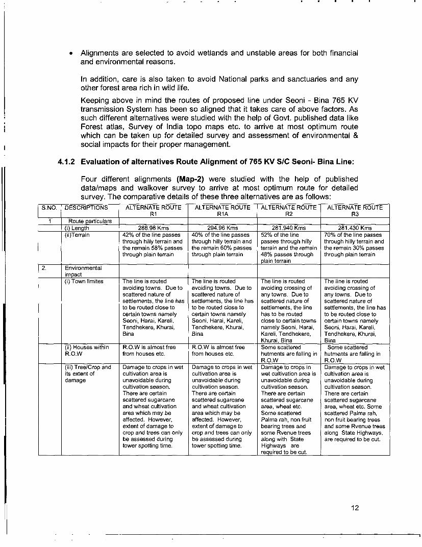
4.1.2 Evaluation of alternatives Route Alignment of 765 KV S/C Seoni- Bina Line:
Four different alignments (Map-2) were studied with the help of publisheddata/maps and walkover survey to arrive at most optimum route for detailedsurvey. The comparative details of these three alternatives are as follows:
S.NO. DESCRIPTIONS ALTERNATE ROUTE ALTERNATE ROUTE ALTERNATE ROUTE ALTERNATE ROUTERl RlA R2 R3
1 Route particulars(i) Length 288.98 Kms 294.96 Kms 281.940 Kms 281.430 Kms(ii)Terrain 42% of the line passes 40% of the line passes 52% of the line 70% of the line passes
through hilly terrain and through hilly terrain and passes through hilly through hilly terrain andthe remain 58% passes the remain 60% passes terrain and the remain the remain 30% passesthrough plain terrain through plain terrain 48% passes through through plain terrain
._________________ plain terrain2. Environmental
impact(i) Town limites The line is routed The line is routed The line is routed The line is routed
avoiding towns. Due to avoiding towns. Due to avoiding crossing of avoiding crossing ofscattered nature of scattered nature of any towns. Due to any towns. Due tosettlements, the line has settlements, the line has scattered nature of scattered nature ofto be routed close to to be routed close to settlements, the line settlements, the line hascertain towns namely certain towns namely has to be routed to be routed close toSeoni, Harai, Kareli, Seoni, Harai, Kareli, close to certain towns certain towns namelyTendhekere, Khurai, Tendhekere, Khurai, namely Seoni, Harai, Seoni, Harai, Kareli,Bina Bina Kareli, Tendhekere, Tendhekere, Khurai,
Khurai, Bina Bina(ii) Houses within R.O.W is almost free R.O.W is almost free Some scattered Some scatteredR.O.W from houses etc. from houses etc. hutments are falling in hutments are falling in
R.O.W R.O.W(iii) Tree/Crop and Damage to crops in wet Damage to crops in wet Damage to crops in Damage to crops in wetits extent of cultivation area is cultivation area is wet cultivation area is cultivation area isdamage unavoidable during unavoidable during unavoidable during unavoidable during
cultivation season. cultivation season. cultivation season. cultivation season.There are certain There are certain There are certain There are certainscattered sugarcane scattered sugarcane scattered sugarcane scattered sugarcaneand wheat cultivation and wheat cultivation area, wheat etc. area, wheat etc. Somearea which may be area which may be Some scattered scattered Palma rah,affected. However, affected. However, Palma rah, non fruit non fruit bearing treesextent of damage to extent of damage to bearing trees and and some Rvenue treescrop and trees can only crop and trees can only some Rvenue trees along State Highways,be assessed during be assessed during along with State are required to be cut.tower spotting time. tower spotting time. Highways are
required to be cut.
12
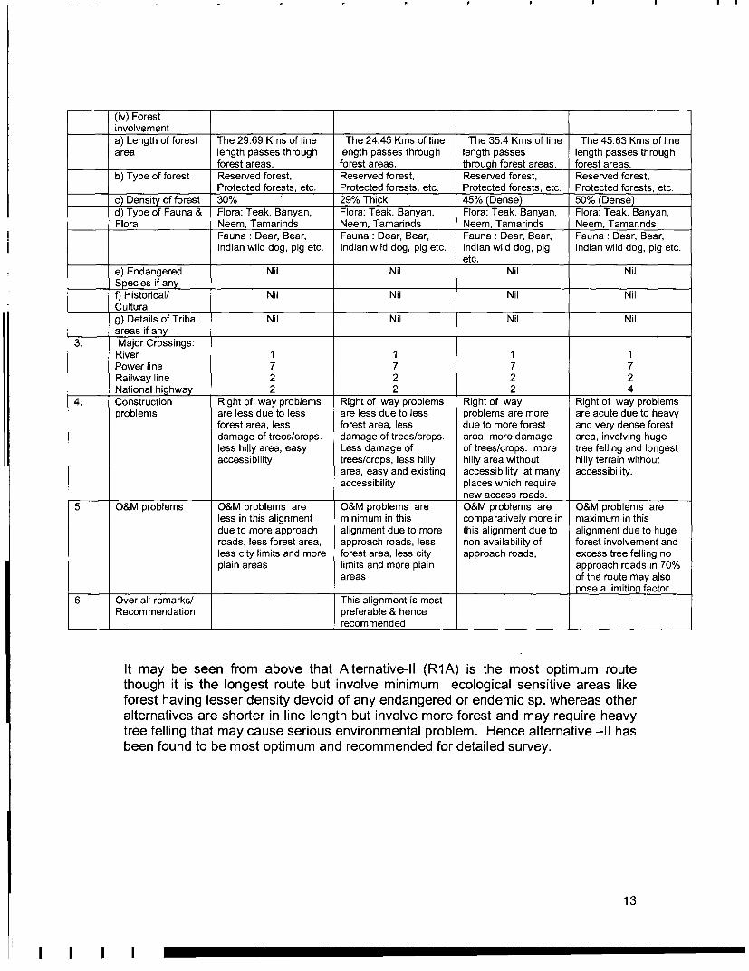
(iv) Forestinvolvementa) Length of forest The 29.69 Kms of line The 24.45 Kms of line The 35.4 Kms of line The 45.63 Kms of linearea length passes through length passes through length passes length passes through
forest areas. forest areas. through forest areas. forest areas.b) Type of forest Reserved forest, Reserved forest, Reserved forest, Reserved forest,
Protected forests, etc. Protected forests, etc. Protected forests, etc. Protected forests, etc.c) Density of forest 30% 29% Thick 45% (Dense) 50% (Dense)d) Type of Fauna & Flora: Teak, Banyan, Flora: Teak, Banyan, Flora: Teak, Banyan, Flora: Teak, Banyan,Flora Neem, Tamarinds Neem, Tamarinds Neem, Tamarinds Neem, Tamarinds
Fauna: Dear, Bear, Fauna: Dear, Bear, Fauna: Dear, Bear, Fauna: Dear, Bear,Indian wild dog, pig etc. Indian wild dog, pig etc. Indian wild dog, pig Indian wild dog, pig etc.
etc.e) Endangered Nil Nil Nil NilSpecies if anyf) Historical/ Nil Nil Nil NilCulturalg) Details of Tribal Nil Nil Nil Nilareas if any
3. Major Crossings:River 1 1 1 1Power line 7 7 7 7Railway line 2 2 2 2National highway 2 2 2 4
4. Construction Right of way problems Right of way problems Right of way Right of way problemsproblems are less due to less are less due to less problems are more are acute due to heavy
forest area, less forest area, less due to more forest and very dense forestdamage of trees/crops. damage of trees/crops. area, more damage area, involving hugeless hilly area, easy Less damage of of trees/crops. more tree felling and longestaccessibility trees/crops, less hilly hilly area without hilly terrain without
area, easy and existing accessibility at many accessibility.accessibility places which require
new access roads.5 O&M problems O&M problems are O&M problems are O&M problems are O&M problems are
less in this alignment minimum in this comparatively more in maximum in thisdue to more approach alignment due to more this alignment due to alignment due to hugeroads, less forest area, approach roads, less non availability of forest involvement andless city limits and more forest area, less city approach roads, excess tree felling noplain areas limits and more plain approach roads in 70%
areas of the route may alsoI_pose a limiting factor.
6 Over all remarks/ This alignment is mostRecommendation preferable & hence
recommended
It may be seen from above that Alternative-Il (R1A) is the most optimum routethough it is the longest route but involve minimum ecological sensitive areas likeforest having lesser density devoid of any endangered or endemic sp. whereas otheralternatives are shorter in line length but involve more forest and may require heavytree felling that may cause serious environmental problem. Hence alternative -Il hasbeen found to be most optimum and recommended for detailed survey.
13

SECTION-V: SCREENING OF POTENTIAL ENVIRONMENTAL IMPACT,EVALUATION AND ITS MANAGEMENT
5.0 Impact Due to Project Location and Design
Environmental impact of transmission line projects are not far reaching and aremostly localized to ROW. However, transmission line project has some affects onnatural and socio-culture resources. These impacts can be minimized by carefulroute selection. In order to get latest information and further optimization of routemodern survey techniques/tools like GIS, GPS aerial photography are also applied.Introduction of GIS and GPS in route selection result in access to updated/latestinformation, through satellite images and further optimization of route having minimalenvironmental impact. Moreover, availability of various details, constraints liketopographical and geotechnical details, forest and environmental details etc. help inplanning the effective mitigative measures including engineering variationsdepending upon the site situation/location. In the instant project also thesetechniques are used and detail survey using GIS/GPS is under progress. Although,all possible measures have been taken during the finalization of route alignment forthe proposed transmission line but due to peculiarity of terrain and demography ofthe area where project is being implemented, some environmental impacts may bethere. The explanations in brief with regard to specific environment review criteriabased on preliminary survey are as follows:
(i) Resettlement
As described earlier all measures are undertaken by POWERGRID at line routingstage itself to avoid settlements such as cities, villages etc. It may be seen from theabove description of proposed route alignment and also keeping in mind that no landis acquired for tower foundation as per existing law, the project does not require anyresettlement of villagers.
The proposed project do not envisages construction of any new substation andextension of only two existing substation is involved where sufficient land is alreadyavailable for proposed bays. Hence no fresh land acquisition or R&R issues areinvolved in the present projects.
(ii) Land value depreciation
Based on past experience land prices are generally expected to rise in the areasreceiving power. Further, transmission lines generally pass through uninhabitedarea, agriculture fields and forests, where the land-use is not going to change inforeseeable future. Therefore, the value of land will not be adversely affected to asignificant degree.
(iii) Historical/cultural monuments/value
As per the POWERGRID's policy of route selection only that route alignment isfinalized this avoids all the historical and cultural monuments. As per the preliminaryassessment carried out during finalization of route alignment in consultation with
14

State revenue authorities and ASI, no such monuments are coming in the proposedroute alignment.
(iv) Encroachment into precious ecological areas
As already explained all precautions have been taken to avoid routing of line throughforest and ecological sensitive areas and National park/Sanctuaries. However,complete avoidance of forest area was not possible though National Park/Sanctuaryor any other protective areas have been completely avoided. But the routes ofproposed transmission line is so finalized that it affect minimum forest area, whichhas also been certified by concerned Divisional Forest Officer (DFO). It may beseen from the above referred tables (para-4.1.2) that out of total transmissionline length of about 294 Km about 24 Km (8% only) length shall pass throughforest land consisting of 156 Ha. forest area in the states of Madhya Pradesh.Prior approval of GOI/MOEF shall be obtained for affected forest under Forest(Conservation) Act, 1980 after detail survey and finalization of route through forestarea in consultation with local forest authorities. Most of the forests to be traversedby the lines are already heavily degraded and the wildlife species present arethose who have been adapted to open or disturbed habitat. Therefore withprovision of Compensatory Afforestation the overall forest status will in manycases improve. Nonetheless, to mitigate losses to existing forests, clearing ofthe transmission line Right-of-way will be done under supervision of ForestDepartment, and some low canopy seed trees and shrubs may be kept intactif they do not interfere with tower erection and line installation. The wood will besold by the Forest Department, who will also retain the sale proceeds. Three-meterwide strips of land under each conductor will be cleared and maintained asmaintenance rows, but the remaining land will be allowed to regenerate. Lopping oftrees to maintain line clearance will be done under the direction of ForestDepartment. POWERGRID will provide construction crews with fuel wood oralternative fuels as a precaution against collection of fuel wood from nearby forest.
Transmission lines can serve as new access routes into previously inaccessible orpoorly accessible forests, thereby accelerating forest and wildlife loss. In such cases,POWERGRID cannot take action itself, but local Forest Department personnel willnormally assess the dangers and take appropriate action, such as establishing guardstations at the entrance to the forest. Given the already easy access anddegraded conditions at the proposed projects sites, this problem is not expected tobe encountered. Nonetheless, POWERGRID staff will report to the ForestDepartment any noticeable encroachment induced by the Projects.
(v) Encroachment into other valuable lands
Impacts on agricultural land will be restricted to the construction phase and whenlarge-scale maintenance measures are required. Some stretch of the line will passthrough Agricultural fields. Agricultural land will be lost at the base of the tower,which is estimated to be 0.2-1 sq. m per average farm holding (Fig-1).
In areas where lines will traverse agricultural land, compensation will be paid toowners for any crop damage incurred as a result of construction activities.
15
POWERGRID field staff will consult affected villagers and local revenue departmentand apprise him about the project and tower location, which shall be erected in theagricultural land, for compensation. Revenue department after evaluating the lossdue to construction activity and productivity of land arrives at the compensation costwhich is paid to farmer. Agricultural activities will be allowed to continue followingthe construction period. If bunds or other on-farm works are disturbed duringconstruction or maintenance, they will be restored to the owner's satisfactionfollowing cessation of construction or maintenance activities. In the event that privatetrees are felled during construction or maintenance operations, compensation will bepaid to the owner in an amount determined by the estimated loss of products fromthe tree over an eight year period (for fruit bearing trees). Agricultural lands underprivate ownership will be identified, and in accordance with normal POWERGRIDprocedures compensation will be paid to the affected villagers. Budgetary provisionRs. 294 lakh @ Rs. 1.00 Lakh per Km is made in the cost estimate to meet theseexpenses.
(vi) Interference with other utilities and traffic
As per regulations enacted by Government of India, it is mandatory forPOWERGRID to seek clearance prior to construction from department of Railways,Telecommunications and wherever necessary from aviation authorities that are likelyto be affected by the construction of transmission lines. The transmission lines affectnearby telecommunication circuits by causing electrical interference. A standingcommittee -- Power Telecom Co-ordination Committee (P.T.C.C.) has beenconstituted by Government of India to plan and implement the mitigating measuresfor the induced voltage which may occur to nearby telecom circuit and suggestnecessary protection measures to be adopted. The committee suggests measureslike rerouting of the telecom circuits, conversion of overhead telecom circuits intocables etc. to minimize the interference.
The cost of such measures is determined by the Committee and is shared byPOWERGRID and Telecom Department on the basis of prevailing norms andguidelines. Though the exact cost to mitigate the impacts of induction in neighboringtelecom circuits would vary from case to case, the cost on an average works out tobe Rs.50000/- per km for POWERGRID. Provision to meet these expenses has beenmade in the cost estimate for the same.
Wherever transmission line crosses the railways, clearance is taken from thatdepartment. In general, the system is planned and executed in such a way thatadequate clearance is maintained between transmission lines on the one hand, andrailways, civil aviation and defense installations on the other. Wherever thetransmission lines pass by the airports the towers beyond specified height arepainted in alternate orange and white stripes for easy visibility and warning lights areplaced atop these towers.
(vii) Interference with drainage pattern
As the transmission lines are constructed aerially and the blockage of groundsurface is limited to area of tower footings, which is very small, there is littlepossibility of affecting drainage pattern. In the infrequent instances where thedrainage is affected, flow will be trained and guided to safe zones.
16

5.1 Environmental Problems Due to Design
(i) Escape of polluting materials
The equipments installed on lines and substations are static in nature and do notgenerate any fumes or waste materials.
(ii) Explosion/fire hazards
During the survey and site selection for transmission lines and sub-stations, it hasbeen ensured that these are kept away from oil/gas pipelines and other sites withpotential for creating explosions or fires.
Fires due to flashover from lines can be a more serious problem in forest. However,adequate safety measures shall be taken to avoid such incidence besides this forestauthorities also incorporate measures like making fire lines to prevent spreading offire in the affected forest area.
(iii) Erosion hazards due to inadequate provision for resurfacing of exposed area
Adequate measures are taken to re-surface the area where excavation works aredone. Topsoil disturbed during the development of sites will be used to restore thesurface of the platform. Infertile and rocky material will be dumped at carefullyselected dumping areas and used as fill for tower foundations.
(iv) Environmental aesthetics
Since spacing between the towers in case of 400 KV lines is approx. 400 metersthese will not affect the visual aesthetics of the localities particularly when it isensured to route the lines as far away from the localities as possible. POWERGRIDtakes up plantation of trees to buffer the visual effect around its substations and toprovide better living conditions. Wherever POWERGRID feels it appropriate,discussions will be held with local Forest Department officials to determine feasibilityof planting trees along roads running parallel to transmission lines to buffer visualeffect in these areas. In addition, towers may be painted grey or green to merge withthe background.
(v) Noise/vibration nuisances
The equipment installed at sub-station are mostly static and are so designed that thenoise level always remains within permissible limits i.e. 85 dB as per Indianstandards. The noise levels reported during normal operating conditions are about60 to 70 dB at 2 m. distance from the equipment. To contain the noise level withinthe permissible limits whenever noise level increases beyond permissible limits,measures like providing sound and vibration dampers and rectification of equipmentare undertaken. In addition, plantations of sound absorbing species like Casuarinas,Tamarind, and Neem are raised at the sub-stations that reduce the sound levelappreciably. It is reported that 93 m3 of woodland can reduce the noise level by 8 dB.Actual noise levels measured at perimeters of existing Substations are 20 to 30 dB.
17

(vi) Blockage of wildlife passage
Since the line is passing through mostly agricultural, wasteland and the affectedforest area is also not a migration path of wild life hence, possibility of disturbance towild life are nil/remote.
5.2 Environmental Problems During Construction Phase
(i) Uncontrolled silt runoff
The Project involves only small scale excavation for tower foundations at scatteredlocations that are re-filled with excavated material therefore uncontrolled silt run off isnot expected.
(ii) Nuisance to nearby properties
As already described in preceding paras, during site selection due care is taken tokeep the transmission line and substations away from settlements. Further, all theconstruction activities will be undertaken through the use of small mechanicaldevices e.g. tractors and manual labour therefore nuisance to the nearby propertiesif any, is not expected.
(iii) Interference with utilities and traffic and blockage of access way
Access to the site will be along existing roads or village paths; minor improvementsto paths may be made where necessary, but no major construction of roads will benecessary either during construction or as a part of maintenance procedures.
As and when a transmission line crosses any road/ railways line, the terminal towersare located at sufficient distance so as not to cause any hindrance to the movementof traffic. Stringing at the construction stage is carried out during lean traffic period inconsultation with the concerned authorities and angle towers are planted to facilitateexecution of work in different stages.
(iv) Inadequate resurfacing for erosion control
Since proposed line is to be constructed in plain area where erosion problem is notanticipated. However, if due to terrain at some points transmission towers may beplaced on slopes and erosion prone soils Internationally accepted engineeringpractices will be undertaken to prevent soil erosion. This will include cutting andfilling slopes wherever necessary. The back cut slopes and downhill slopes will betreated with revetments. As explained above adequate steps shall be taken toresurface the area after construction. Wherever sites are affected by active erosionor landslides, both biological and engineering treatment will be carried out, e.g.provision of breast walls and retaining walls, and sowing soil binding grasses aroundthe site. Furthermore, construction is generally undertaken outside the rainy season.
(v) Inadequate disposition of borrow area
As mentioned earlier the transmission tower foundations involve excavations onsmall scale basis and the excavated soil is utilized for back filling. In case of
18

substations generally the sites are selected in such a manner that the volume ofcutting is equal to volume of filling avoiding borrowing of the area.
(vi) Protection of Worker's health/safety
The Safety Regulations/Safety Manual published by POWERGRID, and included intender documents will guide provisions for workers' health and safety. Variousaspects such as, work and safety regulations, workmen's compensation, insuranceare adequately covered under the Erection Conditions of Contract (ECC), a part ofbidding documents.
In addition training is imparted to the workers in fire fighting and safety measures.Safety tools like helmet, safety belt, gloves etc. are provided to them in accordanceto the provisions of Safety Manual. First aid facilities will be made available with thelabour gangs, and doctors called in from nearby towns when necessary. Thenumber of outside (skilled) labourers will be quite small, of the order of 25-30 peopleper group. The remaining workforce of unskilled labourers will be comprised of localpeople. Workers are also covered by the statutory Workmen (Compensation) Act.POWERGRID has a dedicated unit to oversee all health and safety aspects of itsproject under the Operation Service Deptt. POWERGRID has framedguidelines/checklist for workers' safety as its personnel are exposed to live EHVapparatus and transmission lines. These guidelines/checklist include work permitsand safety precautions for work on the transmission lines both during constructionand operation (Annexure-2 ) and is monitored regularly by site in-charge andcorporate Operation Services.
5.3 Environmental Problems Resulting from Operation
(i) O&M Staff/Skills less than acceptable resulting in variety of adverse effects
The O&M program in POWERGRID is normally implemented by sub-stationpersonnel for both, the lines as well as sub-stations. However in respect of the longdistance transmission lines, there are monitoring offices that are located at variouspoints en-route. Monitoring measures employed include patrolling and thermo-visionscanning.
The supervisors and managers entrusted with O&M responsibilities are intensivelytrained for necessary skills and expertise for handling these aspects.
A monthly preventive maintenance program will be carried out to disclose problemsrelated to cooling oil, gaskets, circuit breakers, vibration measurements, contactresistance, condensers, air handling units, electrical panels and compressors. Anysign of soil erosion is also reported and rectified. Monitoring results are publishedmonthly, including a report of corrective action taken and a schedule for futureaction.
POWERGRID is following the approved international standards and design, whichare absolutely safe. Based on the studies carried out by different countries on thesafety of EHV lines in reference to EMF affect POWERGRID have also carried out
19
such studies with the help of PTI, USA and CPRI, Bangalore on their design. Thestudies inferred that the POWERGRID design are safe and follow the requiredinternational standard. Because of issues relating to need to ensure health andsafety relating to the line such as fire safety, safe voltages on metallic parts ofbuildings, and safety clearances to avoid flashover, the transmission lines will notpass directly over any residential properties and as such the potential for EMFeffects to occur will be further diminished. Given that it will be necessary to ensurethat there are no properties in the ROW beneath and to the sides of the overheadline, automatic mitigation against EMF will be provided between the source ofpotentially high strengths (the transmission line) and the residential properties.
Poly Chlorinated Biphenyls (PCBs) due to its high heat capacity, low flammabilityand low electrical conductivity was extensively used as insulating material incapacitors and transformers. But after the finding that these PCBs are non-biodegradable and has carcinogenic tendency, its use in electrical equipments asinsulating medium has been banned all over the world long back. However, it hasbeen reported in some studies that chances of contamination of oil with PCB ispossible. Keeping that in mind, POWERGRID has taken all possible steps inassociation with NGC, UK and setup Regional testing laboratories for testing ofexisting oil for PCB traces and results of this suggests that PCB contamination is notan issue with POWERGRID. The World Bank has also made following commentsafter a detailed study on Management of PCBs in India:
" Power Grid was the most advanced in testing for PCBs of the organizationsvisited for this project. They have established a procedure for identification ofthe presence of PCBs in transformer oil and more detailed analysis for positiveidentification sample. To date no significant concentrations of PCBs have beendetected. Power Grid do not appear to have any significant issues regardingPCB management and have initiated a testing program. The experience &laboratories of Power Grid could be used to provide a national PCB auditingservice".
5.4 CRITICAL ENVIRONMENTAL REVIEW CRITERIA
(i) Loss of irreplaceable resources
The transmission projects do not involve any large scale excavation and land is lostto the extent of 0.2-1 sq m only for each foundation. As the lines in the subjectproject are not passing through any forest area, the problem of losing naturalresources in this project is not envisages.
(ii) Accelerated use of resources for short-term gains
The project will not be making use of any natural resources occurring in the areaduring construction as well as maintenance phases. The construction material suchas tower members, cement etc shall come from factories while the excavated soilshall be used for backfilling to restore the surface. Thus the project shall not causeany accelerated use of resources for short term gains.
20

(iii) Endangering of species
No endangered species of flora and fauna exist in the project area as well as noreserve forest is getting affected thus there is no possibility of endangering/causingextinction of any species.
(iv) Promoting undesirable rural-to urban migration
The project will not cause any submergence or loss of land holdings that normallytrigger migration. It also does not involve acquisition of any private land holdings.Hence, there is no possibility of any migration.
5.6 PUBLIC CONSULTATION:
Public consultation/information is an integral part of the project implementation.Public is informed about the project at every stage of execution. During survey alsoPOWERGRID's site officials meet people and inform them about the routing oftransmission lines. During the construction, every individual, on whose land tower iserected and people affected by ROW, are consulted.
Apart from this, public consultation using different technique like Public Meeting,Small Group Meeting, informal Meeting as per Environmental Social Policy &Procedures of POWERGRID (ESPP) shall also be carried out during differentactivities of project cycle. During such consultation the public will be informed aboutthe project in general and in particular about the following:
* complete project plan (i.e. its route and terminating point and substations, if any,in between);
* POWERGRID design standards in relation to approved international standards;* Health impacts in relation to EMF;* Measures taken to avoid public utilities such as school, hospitals, etc.;* Other impacts associated with transmission lines and POWERGRID's approach
to minimizing and solving them;* Land acquisition details, proposed R&R measures and compensation packages
in line with POWERGRID's policy;* Trees and crop compensation process.
Apart from organising many informal group meetings in different villages a publicmeeting was also organised in the village Harri of Chindwara distt. of MadhyaPradesh on 28.9.04. To get the maximum participation during the Publicconsultation Programme a notice was served well in advance to the villagers(Annexure- 3). The details of line and its importance was explained to the villagersby the Chief Manager/Seoni. About sixty villagers including Surpanchs, M/s. P.Prabhakar Reddy (Survey Agency) representative and POWERGRID representativeparticipated in the programme (Plate-1 &2). Pamphlets in local language werecirculated during the programme amongst the participants (Annexure-4). Theprogramme was arranged in interactive way and queries like crop compensation etc.were replied. The programme was appreciated by the villagers including Sarpanchand they assured to extend their cooperation for construction of transmission project.
21

The process of such consultation shall continue during project implementation andeven during O&M stage.
5.7 CONCLUSIONS:
From the above discussion, it would seem that the area is rich in physical resources.But careful route selection has avoided involvement of any National Park/Sanctuaryor protected area but involvement of forest could not be avoided due to terrain andother physiographical reasons. Thus route selected for detailed survey is the mostoptimum route alignment and involved minimum forest and no R&R issues areanticipated as no fresh land acquisition is involved in the proposed project. Hence,based on the criteria agreed with Bank the project is coming under the P2 category.The infrastructural constraints are very real and pose a limiting factor on thedevelopment of the area. The above facts while on the one hand underline the needfor implementation of the project for overall development of the area and on anotherhand suggest that a detailed E.I.A. may not be necessary.
22
I SECTION-VI: MONITORING AND ORGANISATIONAL SUPPORT STRUCTURE
6.0 ENVIRONMENTAL MONITORING PROGRAM IN POWERGRID:
Monitoring is a continuous process for POWERGRID projects at all the stages be itthe site selection, construction or maintenance.
The success of POWERGRID lies in its strong monitoring systems. Apart from thesite managers reviewing the progress on daily basis regular project review meetingsare held at least on monthly basis which is chaired by Executive Director of theregion wherein apart from construction issues the environmental aspects of theprojects are discussed and remedial measures taken wherever required. Theexceptions of these meetings are submitted to the Directors and Chairman andManaging Director of the Corporation. The progress of various on-going projects isalso informed to the Board of Directors. Following is the organization support systemfor proper implementation and monitoring of Environmental & Social ManagementPlan:
6.1 Corporate Level
An Environmental Management Cell at corporate level was created withinPOWERGRID in 1992 and subsequently upgraded to an Environment ManagementDepartment (EMD) in 1993 and in 1997 it has been further upgraded to Environment& Social Management Deptt. (ESMD) by incorporating social aspect of project.Briefly, the ESMD's responsibilities are as follows:
* Advising and coordinating RHQs and Site to carry out environmentaland social surveys for new projects.
* Assisting RHQs and site to finalize routes of entire power transmissionline considering environmental and social factors that could ariseenroute
* Help RHQs and Site to follow-up with the state forest offices and otherstate departments in expediting forest clearances and the landacquisition process of various ongoing and new projects
* Act as a focal point for interaction with the MOEF for expediting forestclearances and follow-ups with the Ministry of Power.
* Imparts training to POWERGRID's RHQs & site Officials onenvironment and social issues and their management plan.
6.2 Regional Level
At its Regional Office POWERGRID has a Environmental and Social Managementcell (ESMC) to manage Environmental and Social issues and to coordinate betweenESMD at the Corporate level and the Divisional Headquarters. The key functionsenvisaged for ESMC are:
23

* Advising and coordinating field offices to carry out environmental andsocial surveys for new projects envisaged in the Corporate InvestmentPlan
* Assisting the ESMD and DHQs to finalise routes of entire powertransmission lines considering the environmental and social factors thatcould arise en-route
* To follow-up forest clearances and land acquisition processes withstate forest offices and other state departments for various ongoingand new projects
* Acting as a focal point for interaction with the ESMD and DHQs onvarious environmental and social aspects.
6.3 Site Office
At the Divisional Headquarters level, POWERGRID has made the head of thedivision responsible for implementing the Environmental and Social aspect of projectand are termed as Environmental and Social Management Team (ESMT) . Keyfunctions of the ESMT are:
* Conduct surveys on environmental and social aspects to finalise theroute for the power transmission projects
* Conduct surveys for the sites to being considered for land acquisition* Interact with the Forest Departments to make the forest proposal and
follow it up for MOEF clearance.* Interact with Revenue Authorities for land acquisition and follow it up
with Authorised Agencies for implementation of Social ManagementPlan (SMP).
* Implementation of Environment Management Plan (EMP) and SMP* Monitoring of EMP and SMP and producing periodic reports on the
same.
It may be noted that POWERGRID is well equipped to implement and monitor itsenvironment and Social Management plans.
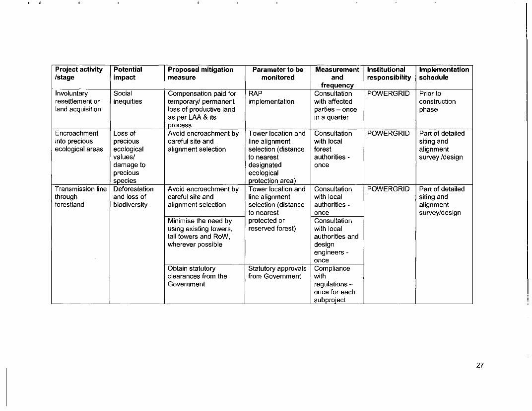
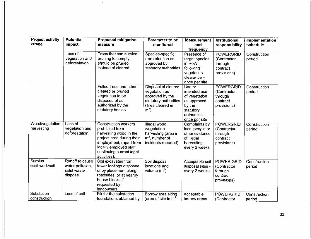
As regards monitoring of impacts on ecological resources particularly in Forest,Sanctuary or National Park, it is generally done by the concerned Divisional ForestOfficer, Chief Wildlife Warden and their staff as a part of their normal duties. Amonitoring system (done by the Forest Department) is also in place forcompensatory forests established as part of the Project. A detailed EnvironmentManagement Plan (EMP) including monitoring plan for all possibleenvironmental and social impact and its proper management has been drawn(Table- 6.1) and will be implemented during various stage of project execution.
Environmental Review: Periodic review by corporate ESMD and highermanagement including review by POWERGRID CMD of all environmental and socialissues is under taken to ensure that EMP and other measures are implemented atsite. Besides it annual review by independent Auditor under ISO: 14001 shall also beundertaken for compliance of agreed policy and management plan.
24

Table-6.1 Environment Management Plan
Project activity Potential Proposed mitigation Parameter to be Measurement Institutional Implementation/stage impact measure monitored and responsibility schedule
frequencyPre-constructionLocation of Exposure to Setback of dwellings to Tower location and Setback POWERGRID Part of towertransmission safety related overhead line route line alignment distances to siting surveytowers and risks designed in accordance selection with nearest and detailedtransmission line with permitted level of respect to nearest houses - once alignmentalignment and power frequency and dwellings survey anddesign the regulation of design
supervision at sites.Equipment Release of PCBs not used in Transformer design Exclusion of POWERGRID Part of tenderspecifications chemicals and substation transformers PCBs in specificationsand design gases in or other project facilities transformers for theparameters receptors (air, or equipment. stated in equipment
water, land) tenderspecification -once
Processes, equipment Process, Exclusion of POWERGRID Part of tenderand systems not to use equipment and CFCs stated in specificationschlorofluorocarbons system design tender for the(CFCs), including halon, specification - equipmentand their use, if any, in onceexisting processes andsystems should bephased out and to be Phase out Part ofdisposed of in a manner schedule to be equipment andconsistent with the prepared in process designrequirements of the case still in useGovernment - once
Transmission line Exposure to Transmission line Electromagnetic Line design POWERGRID Part of detaileddesign electromagnetic design to comply with field strength for compliance alignment
25

Project activity Potential Proposed mitigation Parameter to be Measurement Institutional Implementation/stage impact measure monitored and responsibility schedule
frequencyinterference the limits of proposed line with relevant survey and
electromagnetic design standards - designinterference from onceoverhead power lines
Substation Exposure to Design of plant Expected noise Compliance POWERGRID Part of detailedlocation and noise enclosures to comply emissions based with siting surveydesign with noise regulations. on substation regulations - and design
design onceLocation of Impact on Consideration of tower Tower location and Consultation POWERGRID Part of towertransmission water bodies location at where they line alignment with local siting surveytowers and and land could be located to selection (distance authorities and and detailedtransmission line avoid water bodies or to water and/or land owners - alignmentalignment and agricultural land. agricultural land) once survey anddesign design
Social Careful route selection Tower location and Consultation POWERGRID Part of detailedinequities to avoid existing line alignment with local tower siting and
settlements selection (distance authorities and alignmentto nearest land owners - survey anddwellings or social once designinstitutions)
Minimise need to Tower location and Consultation POWERGRID Part of detailedacquire agricultural land line alignment with local tower siting and
selection (distance authorities and alignmentto agricultural land) land owners - survey and
once design
26
Project activity Potential Proposed mitigation Parameter to be Measurement Institutional Implementation/stage impact measure monitored and responsibility schedule
frequencyInvoluntary Social Compensation paid for RAP Consultation POWERGRID Prior toresettlement or inequities temporary/ permanent implementation with affected constructionland acquisition loss of productive land parties - once phase
as per LAA & its in a quarterprocess
Encroachment Loss of Avoid encroachment by Tower location and Consultation POWERGRID Part of detailedinto precious precious careful site and line alignment with local siting andecological areas ecological alignment selection selection (distance forest alignment
values/ to nearest authorities - survey /designdamage to designated onceprecious ecologicalspecies protection area)
Transmission line Deforestation Avoid encroachment by Tower location and Consultation POWERGRID Part of detailedthrough and loss of careful site and line alignment with local siting andforestland biodiversity alignment selection selection (distance authorities - alignment
to nearest once survey/designMinimise the need by protected or Consultationusing existing towers, reserved forest) with localtall towers and RoW, authorities andwherever possible design
engineers -once
Obtain statutory Statutory approvals Complianceclearances from the from Government withGovernment regulations -
once for eachsubproject
27

Project activity Potential Proposed mitigation Parameter to be Measurement Institutional Implementation/stage impact measure monitored and responsibility schedule
frequencyEncroachment Loss of Use existing tower Tower location and Consultation POWERGRID Part of detailedinto farmland agricultural footings/towers line alignment with local alignment
productivity wherever possible selection authorities and survey anddesign designengineers -once
Avoid siting new towers Tower location and Consultation Part of detailedon farmland wherever line alignment with local siting andfeasible selection authorities and alignment
design survey /designengineers -once
Farmers compensated Design of Consultation Prior tofor any permanent loss Implementation of with affected constructionof productive land Crop parties - once phase
Compensation in a quarter(based on affectedarea)
Farmers/landowners Design of Consultation Prior tocompensated for Implementation of with affected constructionsignificant trees that Tree compensation parties - once phaseneed to be trimmed/ (estimated area to in a quarterremoved along RoW. be
trimmed/removed)Statutory approvals Compliance Part of detailedfor tree trimming with siting and/removal regulations - alignment
once for each survey /designsubproject
Noise related Nuisance to Substations sited and Noise levels Noise levels to POWERGRID Part of detailedneighbouring designed to ensure be specified in equipment
L__________ _ | properties noise will not be a tender | design
28

Project activity Potential Proposed mitigation Parameter to be Measurement Institutional Implementation/stage impact measure monitored and responsibility schedule
frequencynuisance. documents -
onceInterference with Flooding Appropriate siting of Tower location and Consultation POWERGRID Part of detaileddrainage hazards/loss of towers to avoid channel line alignment with local alignmentpatterns/Irrigation agricultural interference selection (distance authorities and survey andchannels production to nearest flood design design
zone) engineers -once
Escape of Environmental Transformers designed Equipment Tender POWERGRID Part of detailedpolluting pollution with oil spill containment specifications with document to equipmentmaterials systems, and purpose- respect to potential mention design
built oil, lubricant and pollutants specifications - /drawingsfuel storage system, oncecomplete with spillcleanup equipment.Substations to include Substation sewage Tender POWERGRID Part of detaileddrainage and sewage design document to substationdisposal systems to mention layout andavoid offsite land and detailed designwater pollution. specifications - /drawings
onceExplosions/Fire Hazards to life Design of substations to Substation design Tender POWERGRID Part of detailed
include modern fire compliance with document to substationcontrol fire prevention and mention layout andsystems/firewalls. control codes detailed designProvision of fire fighting specifications - /drawingsequipment to be located onceclose to transformers.
ConstructionEquipment layout Noise and Construction techniques Construction Construction POWERGRID Constructionand installation vibrations and machinery selection techniques and techniques and (Contractor period
seeking to minimize machinery machinery through
29

Project activity Potential Proposed mitigation Parameter to be Measurement Institutional Implementation/stage impact measure monitored and responsibility schedule
frequencyground disturbance. creating contract
minimal provisions)grounddisturbance -once at thestart of eachconstructionphase
Physical Disturbed Construction activities Timing of start of Crop POWERGRID Constructionconstruction farming activity on cropping land timed construction disturbance - (Contractor period
to avoid disturbance of Post harvest throughfield crops (within one as soon as contractmonth of harvest possible but provisions)wherever possible). before next
crop - once persite
Mechanized Noise, vibration Construction equipment Construction Complaints POWERGRID Constructionconstruction and operator to be well maintained. equipment - received by (Contractor period
safety, efficient estimated noise local throughoperation emissions authorities - contract
every 2 weeks provisions)Noise, Turning off plant not in Construction Complaints POWERGRID Constructionvibration, use. equipment - received by (Contractor periodequipment estimated noise local throughwear and tear emissions and authorities - contract
operating every 2 weeks provisions)schedules
30

Project activity Potential Proposed mitigation Parameter to be Measurement Institutional Implementation/stage impact measure monitored and responsibility schedule
frequencyConstruction of Increase in Existing roads and Access roads, Use of POWERGRID Constructionroads for airborne dust tracks used for routes (length and established (Contractor periodaccessibility particles construction and width of new roads through
maintenance access to access roads to be wherever contractthe line wherever constructed) possible - provisions)possible. every 2 weeks
Increased land New access ways Access width Access POWERGRID Constructionrequirement for restricted to a single (meters) restricted to (Contractor periodtemporary carriageway width within single throughaccessibility the RoW. carriageway contract
width within provisions)RoW - every 2weeks
Temporary Overflows, Temporary placement of Temporary fill Absence of fill POWERGRID Constructionblockage of reduced fill in drains/canals not placement (m3) in sensitive (Contractor periodutilities discharge permitted. drainage areas through
- every 4 contractweeks provisions)
Site clearance Vegetation Marking of vegetation to Vegetation marking Clearance POWERGRID Constructionbe removed prior to and clearance strictly limited (Contractor periodclearance, and strict control (area in m2 ) to target throughcontrol on clearing vegetation - contractactivities to ensure every 2 weeks provisions)minimal clearance.
Trimming/cutting Fire hazards Trees allowed growing Species-specific Presence of POWERGRID Constructionof trees within up to a height within the tree retention as target species (Contractor periodRoW RoW by maintaining approved by in RoW through
adequate clearance statutory authorities following contractbetween the top of tree (average and vegetation provisions)and the conductor as maximum tree clearance -per the regulations. height at maturity, once per site
in meters)
31
Project activity Potential Proposed mitigation Parameter to be Measurement Institutional Implementation/stage impact measure monitored and responsibility schedule
frequencyLoss of Trees that can survive Species-specific Presence of POWERGRID Constructionvegetation and pruning to comply tree retention as target species (Contractor perioddeforestation should be pruned approved by in RoW through
instead of cleared. statutory authorities following contractvegetation provisions)clearance -once per site
Felled trees and other Disposal of cleared Use or POWERGRID Constructioncleared or pruned vegetation as intended use (Contractor periodvegetation to be approved by the of vegetation throughdisposed of as statutory authorities as approved contractauthorized by the (area cleared in by the provisions)statutory bodies. mi2 ) statutory
authorities -once per site
Wood/vegetation Loss of Construction workers Illegal wood Complaints by POWERGRID Constructionharvesting vegetation and prohibited from /vegetation local people or (Contractor period
deforestation harvesting wood in the harvesting (area in other evidence throughproject area during their m2 , number of of illegal contractemployment, (apart from incidents reported) harvesting - provisions)locally employed staff every 2 weekscontinuing current legalactivities).
Surplus Runoff to cause Soil excavated from Soil disposal Acceptable soil POWER GRID Constructionearthwork/soil water pollution, tower footings disposed locations and disposal sites - (Contractor period
solid waste of by placement along volume (m3) every 2 weeks throughdisposal roadsides, or at nearby contract
house blocks if provisions)requested bylandowners.
Substation Loss of soil Fill for the substation Borrow area siting Acceptable POWERGRID Constructionconstruction foundations obtained by (area of site in m2 borrow areas (Contractor period
32

Project activity Potential Proposed mitigation Parameter to be Measurement Institutional Implementation/stage impact measure monitored and responsibility schedule
frequencycreating or improving and estimated that provide a throughlocal water supply volume in m3) benefit - every contractponds or drains, with the 2 weeks provisions)agreement of localcommunities.
Substation Water pollution Construction activities Seasonal start and Timing of POWERGRID Constructionconstruction involving significant finish of major major (Contractor period
ground disturbance (i.e. earthworks disturbance throughsubstation land forming) activities - prior contractnot undertaken during to start of provisions)the monsoon season. construction
activitiesSite clearance Vegetation Tree clearances for Ground Amount of POWERGRID Construction
easement establishment disturbance during ground (Contractor periodto only involve cutting vegetation disturbance - throughtrees off at ground level clearance (area, every 4 weeks contractor pruning as mi2) provisions)appropriate, with tree Statutory approvals Statutory POWERGRID Constructionstumps and roots left in approvals for (Contractor periodplace and ground cover tree throughleft undisturbed. clearances - contract
once for each provisions)site
Tower Waste disposal Excess fill from tower Location and Appropriate fill POWERGRID Constructionconstruction - foundation excavation amount (m3)of fill disposal (Contractor perioddisposal of disposed of next to disposal locations - throughsurplus roads or around houses, every 2 weeks contractearthwork/fill in agreement with the provisions)
local community orlandowner.
Storage of Contamination Fuel and other Location of Fuel storage in POWERGRID Constructionchemicals and of receptors hazardous materials hazardous material appropriate (Contractor period
33
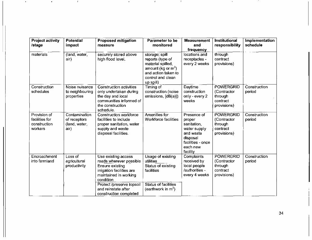
Project activity Potential Proposed mitigation Parameter to be Measurement Institutional Implementation/stage impact measure monitored and responsibility schedule
frequencymaterials (land, water, securely stored above storage; spill locations and through
air) high flood level. reports (type of receptacles - contractmaterial spilled, every 2 weeks provisions)amount (kg or m3)and action taken tocontrol and cleanup spill)
Construction Noise nuisance Construction activities Timing of Daytime POWERGRID Constructionschedules to neighbouring only undertaken during construction (noise construction (Contractor period
properties the day and local emissions, [dB(a)]) only - every 2 throughcommunities informed of weeks contractthe construction provisions)schedule.
Provision of Contamination Construction workforce Amenities for Presence of POWERGRID Constructionfacilities for of receptors facilities to include Workforce facilities proper (Contractor periodconstruction (land, water, proper sanitation, water sanitation, throughworkers air) supply and waste water supply contract
disposal facilities. and waste provisions)disposalfacilities - onceeach newfacility
Encroachment Loss of Use existing access Usage of existing Complaints POWERGRID Constructioninto farmland agricultural roads wherever possible utilities received by (Contractor period
productivity Ensure existing Status of existing local people throughirrigation facilities are facilities /authorities - contractmaintained in working every 4 weeks provisions)conditionProtect /preserve topsoil Status of facilitiesand reinstate after (earthwork in m3)construction completed
34

Project activity Potential Proposed mitigation Parameter to be Measurement Institutional Implementation/stage impact measure monitored and responsibility schedule
frequencyRepair /reinstate Status of facilitiesdamaged bunds etc (earthwork in m3)after constructioncompleted
Social Compensation for Implementation of Consultation POWERGRID Prior toinequities temporary loss in Crop compensation with affected construction
agricultural production (amount paid, parties - oncedates, etc.) in a quarter
Uncontrolled Soil loss, Need for access tracks Design basis and Incorporating POWERGRID Constructionerosion/silt runoff downstream minimised, use of construction good design (Contractor period
siltation; existing roads. procedures and throughLimit site clearing to (suspended solids construction contractwork areas in receiving waters; management provisions)Regeneration of area re-vegetated practices -vegetation to stabilise in m2; amount of once for eachworks areas on bunds constructed sitecompletion (where [length in meter,applicable) area in m2, orAvoidance of excavation volume in in])in wet seasonWater courses protectedfrom siltation throughuse of bunds andsediment ponds
Nuisance to Losses to Contract clauses Contract clauses Incorporating POWERGRID Constructionnearby neighbouring specifying careful good (Contractor periodproperties land uses/ construction practices. construction through
values management contractpractices - provisions)once for eachsite
35

Project activity Potential Proposed mitigation Parameter to be Measurement Institutional Implementation/stage impact measure monitored and responsibility schedule
frequencyAs much as possible Design basis and Incorporatingexisting access ways layout good designwill be used. engineering
practices -once for eachsite
Productive land will be Reinstatement of Consultationreinstated following land status (area with affectedcompletion of affected, m2 ) parties - twiceconstruction - immediately
aftercompletion ofconstructionand after thefirst harvest
Social Compensation will be Implementation of Consultation POWERGRID Prior toinequities paid for loss of Tree/Crop with affected construction
production, if any. compensation parties - once(amount paid) in a quarter
Inadequate siting Loss of land Existing borrow sites will Contract clauses Incorporating POWERGRID Constructionof borrow areas values be used to source good (Contractor period
aggregates, therefore, construction throughno need to develop new management contractsources of aggregates practices - provisions)
once for eachsite
Health and Injury and Contract provisions Contract clauses Contract POWERGRID Constructionsafety sickness of specifying minimum (number of clauses (Contractor period
workers and requirements for incidents and total compliance - throughconstruction camps
36
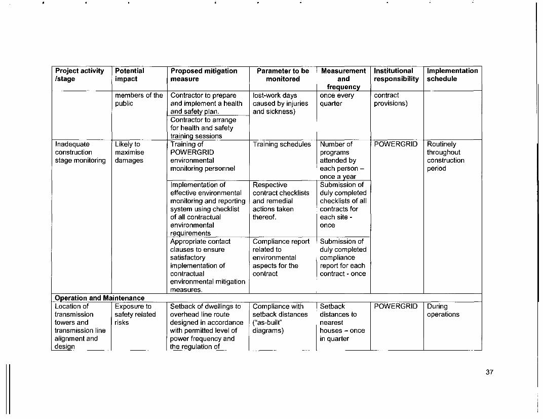
Project activity Potential Proposed mitigation Parameter to be Measurement Institutional Implementation/stage impact measure monitored and responsibility schedule
frequencymembers of the Contractor to prepare lost-work days once every contractpublic and implement a health caused by injuries quarter provisions)
and safety plan. and sickness)Contractor to arrangefor health and safetytraining sessions
Inadequate Likely to Training of Training schedules Number of POWERGRID Routinelyconstruction maxim ise POWERGRI D programs throughoutstage monitoring damages environmental attended by construction
monitoring personnel each person - periodonce a year
Implementation of Respective Submission ofeffective environmental contract checklists duly completedmonitoring and reporting and remedial checklists of allsystem using checklist actions taken contracts forof all contractual thereof. each site -environmental oncerequirementsAppropriate contact Compliance report Submission ofclauses to ensure related to duly completedsatisfactory environmental complianceimplementation of aspects for the report for eachcontractual contract contract - onceenvironmental mitigationmeasures.
Operation and MaintenanceLocation of Exposure to Setback of dwellings to Compliance with Setback POWERGRID Duringtransmission safety related overhead line route setback distances distances to operationstowers and risks designed in accordance ("as-built" nearesttransmission line with permitted level of diagrams) houses - oncealignment and power frequency and in quarterdesign the regulation of
37
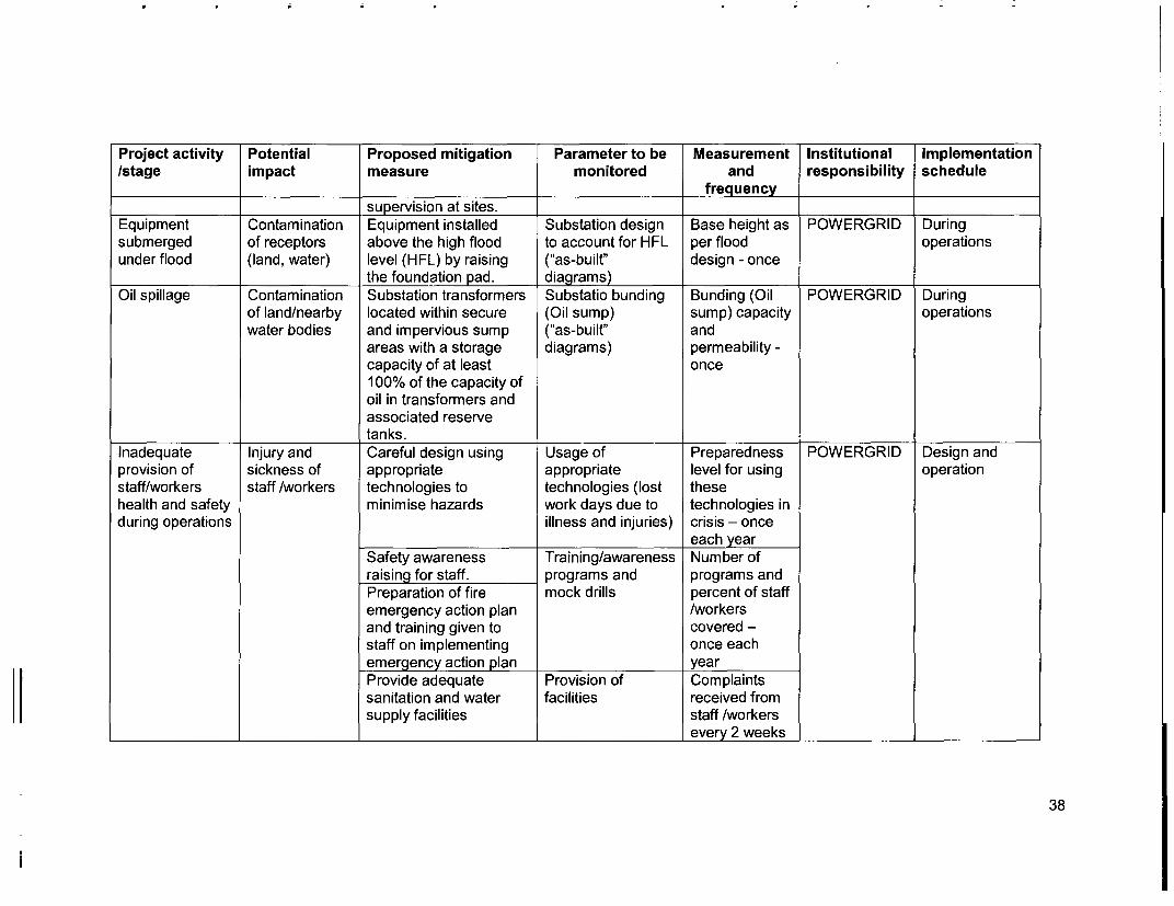
Project activity Potential Proposed mitigation Parameter to be Measurement Institutional Implementation/stage impact measure monitored and responsibility schedule
frequencysupervision at sites.
Equipment Contamination Equipment installed Substation design Base height as POWERGRID Duringsubmerged of receptors above the high flood to account for HFL per flood operationsunder flood (land, water) level (HFL) by raising ("as-built" design - once
the foundation pad. diagrams)Oil spillage Contamination Substation transformers Substatio bunding Bunding (Oil POWERGRID During
of land/nearby located within secure (Oil sump) sump) capacity operationswater bodies and impervious sump ("as-built" and
areas with a storage diagrams) permeability -capacity of at least once100% of the capacity ofoil in transformers andassociated reservetanks.
Inadequate Injury and Careful design using Usage of Preparedness POWERGRID Design andprovision of sickness of appropriate appropriate level for using operationstaff/workers staff /workers technologies to technologies (lost thesehealth and safety minimise hazards work days due to technologies induring operations illness and injuries) crisis - once
each yearSafety awareness Training/awareness Number ofraising for staff. programs and programs andPreparation of fire mock drills percent of staffemergency action plan /workersand training given to covered -staff on implementing once eachemergency action plan yearProvide adequate Provision of Complaintssanitation and water facilities received fromsupply facilities staff /workers
l______________ l_____________ __ _________________ __ every 2 w eeks _ l _l_l
38

Project activity Potential Proposed mitigation Parameter to be Measurement Institutional Implementation/stage impact measure monitored and responsibility schedule
frequencyElectric Shock Injury/mortality Careful design using Usage of Preparedness POWERGRID Design andHazards to staff and appropriate appropriate level for using Operation
public technologies to technologies theseminimise hazards (number of injury technologies in
incidents, lost work crisis - once adays) month
Security fences around Maintenance of Report onsubstations fences maintenance -Barriers to prevent Maintenance of every 2 weeksclimbing on/dismantling barriersof transmission towersAppropriate warning Maintenance ofsigns on facilities warning signsElectricity safety Training Number ofawareness raising in /awareness programs andproject areas programs and percent of total
mock drills for all personsconcerned parties covered -
once eachyear
Operations and Unnecessary Adequate training in Training/awareness Number of POWERGRID Operationmaintenance environmental O&M to all relevant staff programs and programs andstaff skills less losses of of substations and mock drills for all percent of staffthan acceptable various types transmission line relevant staff covered -
maintenance crews. once eachPreparation and training yearin the use of O&Mmanuals and standardoperating practices.
Inadequate Diminished Power Grid staff to Training/awareness Number of POWERGRID Operationperiodic ecological and receive training in programs and programs and | l _l
39

Project activity Potential Proposed mitigation Parameter to be Measurement Institutional Implementation/stage impact measure monitored and responsibility schedule
frequencyenvironmental social values. environmental mock drills for all percent of staffmonitoring. monitoring of project relevant staff covered -
operations and once eachmaintenance activities. year
Equipment Release of Processes, equipment Process, Phase out POWERGRID Operationsspecifications chemicals and and systems using equipment and schedule to beand design gases in cholofluorocarbons system design prepared inparameters receptors (air, (CFCs), including halon, case still in use
water, land) should be phased out - once in aand to be disposed of in quartera manner consistentwith the requirements ofthe Government.
Transmission line Exposure to Transmission line Required ground Ground POWERGRID Operationsmaintenance electromagnetic design to comply with clearance (meters) clearance -
interference the limits of onceelectromagneticinterference fromoverhead power lines
Noise related Nuisance to Substations sited and Noise levels Noise levels at POWERGRID Operationsneighbouring designed to ensure (dB(a)) boundaryproperties noise will not be a nearest to
nuisance. properties andconsultationwith affectedparties if any -once
40

ANNEXURE- 1
POWER MAP OF WESTERN REGIONTRANSMISSION GRID HIGHLIGHTING THE
PRESENT PROJECT

SEONJ-U]NA VStYV SIC CJARGQD 4ATkV LVE V 1 ?wA
u nn
q rh 3X .m
1_ 0W1
-~~~~~~~~~~~~~.

ANNEXURE- 2
HEALTH AND SAFETY CHECKLIST
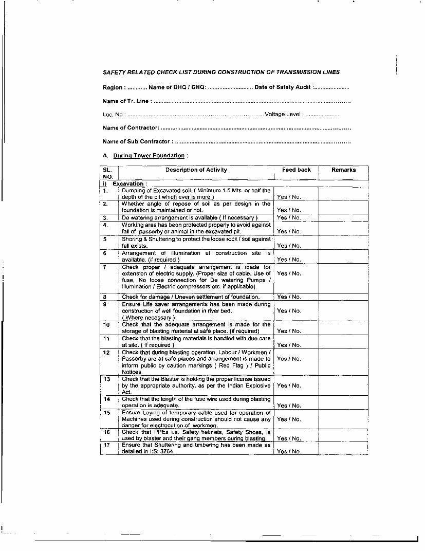
SAFETY RELATED CHECK LIST DURING CONSTRUCTION OF TRANSMISSION LINES
Region: .... Name of DHQ I GHQ: ......... ....... Date of Safety Audit :
Nam e of Tr. Line: ........................................................................................................................
Loc. No:................. Voltage Level:
Name of Contractor: ....................................................................................................................
Name of Sub Contractor: ...........................................................................................................
A. During Tower Foundation:
SL.| Description of Activity Feed back RemarksNO.i) Excavation:1. Dumping of Excavated soil. ( Minimum 1.5 Mts. or half the
depth of the pit which ever is more ) Yes / No.2. Whether angle of repose of soil as per design in the
foundation is maintained or not. Yes / No.3. De watering arrangement is available ( If necessar ) Yes / No.4. Working area has been protected properly to avoid against
fall of passerby or animal in the excavated pit. Yes I No.5 Shoring & Shuttering to protect the loose rock / soil against
_____ 'fall exists. Yes / No.
6 Arrangement of illumination at construction site isavailable. (if required ) Yes / No.
7 Check proper I adequate arrangement is made forextension of electric supply. (Proper size of cable, Use of Yes / No.fuse, No loose connection for De watering Pumps /Illumination / Electric compressors etc. if applicable).
8 Check for damage / Uneven settlement of foundation. Yes / No.9 Ensure Life saver arrangements has been made during
construction of well foundation in river bed. Yes / No.(Where necessary) _
10 Check that the adequate arrangement is made for the_____ storage of blasting material at safe place. (if required) Yes / No.
11 Check that the blasting materials is handled with due careat site. ( If required ) Yes / No.
12 Check that during blasting operation, Labour / Workmen /Passerby are at safe places and arrangement is made to Yes / No.inform public by caution markings ( Red Flag ) I PublicNotices.
13 Check that the Blaster is holding the proper license issuedby the appropriate authority. as per the Indian Explosive Yes / No.Act.
14 Check that the length of the fuse wire used during blastingoperation is adequate. Yes / No.
15 Ensure Laying of temporary cable used for operation ofMachines used during construction should not cause any Yes / No.danger for electrocution of workmen.
1 6 Check that PPEs i.e. Safety helmets, Safety Shoes, isI____ used by blaster and their gang members during blasting. Yes / No.17 Ensure that Shuttering and timbering has been made as
l detailed in l:S: 3764. Yes / No. |.

| 'Ensure that before undertaking excavation, the soil hasbeen tested and in case of availability of any explosive I Yes / No.dangerous gas, necessary arrangement must be made toremove / dilute such gases.
19 The positions of underground installations such as sewers,water pipes and electrical cables has been verified and in Yes / No.
case of their existence, they must be isolated.20 Arrangement shall be made to prevent external vibrations
due to rail / road traffic ( If required ). Yes / No.
21 Safety is ensured during the construction of Tr. Lines forbuildings, structures etc. which are coming in the vicinity of Yes / No.the excavated area from collapse. ( If required )
22 Check that sufficient strong ladder of suitable length isavailable for ingress / outgress of persons in the pit Yes I No.
23 Lone worker should not be allowed to work in theexcavated area beyond shoulder level. Yes / No.
24 Check for any possibility of seepage of water from nearbypond I river should be estimated and taken care of. Yes / No.
25 After excavation the work has been completed speedilyand back filling done at the earliest. Yes / No.
2626__ ______________________________________________ Yes / No.
27Yes / No.
1 28 Yes I No.
ii) Casting of Foundation I Concreting1 Check construction materials are stacked at safe place
and also does not cause any danger.(Away from pit by 1.5 Yes / No.Mtrs. Or half the depth of pit, which ever is more. )
2 Check arrangement of illumination at Construction Site. ( Ifrequired ). Yes / No.
3 Ensure life saver arrangements has been made duringconstruction of Well foundation in River Bed. Yes / No.
4 Check that the Concreting Mixer machine is placed at asafe place. (Not very near to pit.) Yes I No.
5 Check proper / adequate arrangement is made forextension of electric supply. (Proper size of cable, Use of Yes / No.fuse, No loose connection for De watering Pumps I
Illumination I Electric compressors etc. if applicable).
6 Check that laying of temporary cables used duringconstruction activities should not cause any danger for Yes / No.electrocution to workmen.
7 Inspection of excavations shall be made by a CompetentPerson every day. In case, possible cave in or slide is Yes / No.apparent, all working in the excavation shall be seized untilthe necessary precautions have been taken to safeguardthe possible cave in or slide.
8 Jacks and vertical supports shall be positioned in such amanner that the vertical loads are distributed equally and Yes / No.do not exceed the capacity of the jacks and the jacks areplaced away from pit edge etc.
9 Proper Jacking arrangement is made to take the entireload of template. Yes I No.
10 In case of long template in stub setting, more jacks hasbeen provided and check that the Jacks are placed on Yes / No.leveled and hard surface to avoid the unbalancing andfallen.
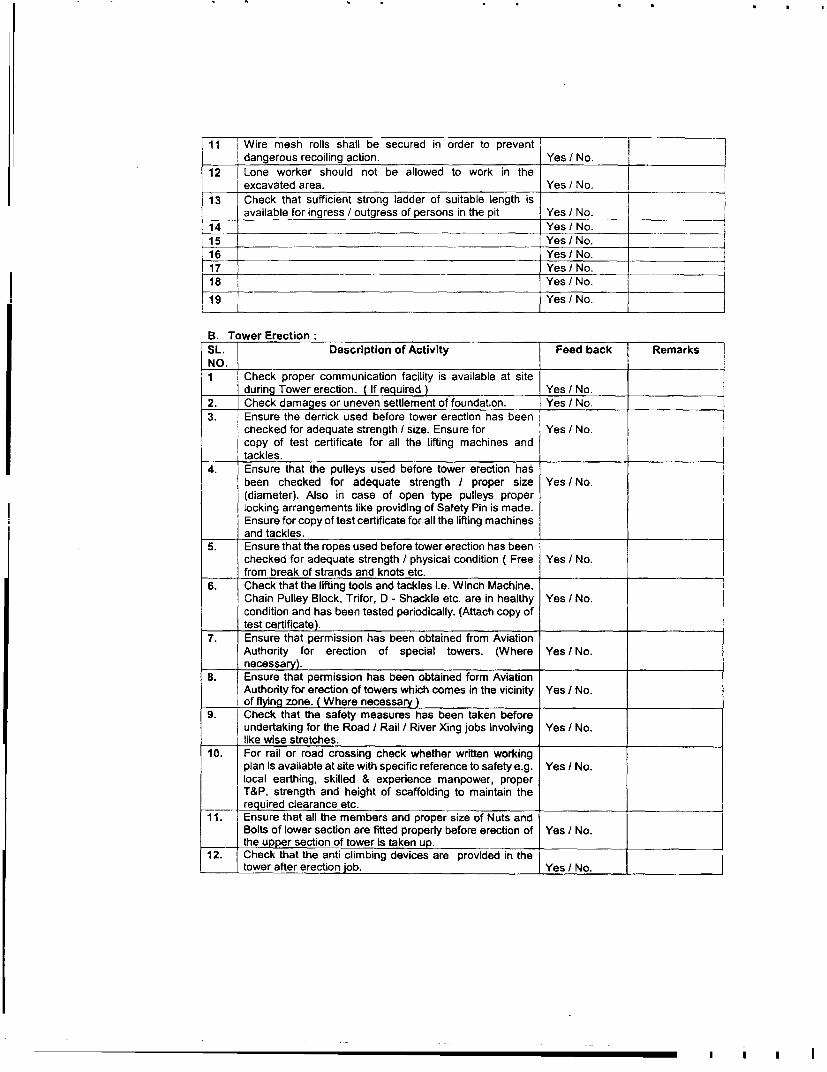
11 Wire mesh rolls shall be secured in order to prevent l Fdangerous recoiling action. Yes / No. l
12 Lone worker should not be allowed to work in theexcavated area. Yes / No.
13 Check that sufficient strong ladder of suitable length isavailable for ingress / outgress of persons in the pit Yes / No.
14 Yes / No.
15 Yes / No.
16 _ Yes / No.1 7 jYes / No.
18 Yes / No.
19 Yes / No.
B. Tower Erection:SL. Description of Activity Feed back Remarks l
NO. l1 Check proper communication facility is available at site
during Tower erection. ( If required ) Yes / No.2. Check damages or uneven settlement of foundation. Yes / No.3. Ensure the derrick used before tower erection has been
checked for adequate strength I size. Ensure for Yes / No.copy of test certificate for all the lifting machines andtackles.
4. I Ensure that the pulleys used before tower erection hasbeen checked for adequate strength I proper size Yes / No.(diameter). Also in case of open type pulleys properlocking arrangements like providing of Safety Pin is made.Ensure for copy of test certificate for all the lifting machinesand tackles.
5. Ensure that the ropes used before tower erection has beenchecked for adequate strength / physical condition ( Free Yes / No.
_____ - from break of strands and knots etc.
6. Check that the lifting tools and tackles i.e. Winch Machine,Chain Pulley Block, Trifor, D - Shackle etc. are in healthy Yes I No.condition and has been tested periodically. (Attach copy oftest certificate).
7. Ensure that permission has been obtained from AviationAuthority for erection of special towers. (Where Yes / No.necessary).
8. Ensure that permission has been obtained form AviationAuthority for erection of towers which comes in the vicinity Yes t No.
____ of flving zone. (Where necessary)9. Check that the safety measures has been taken before
undertaking for the Road / Rail / River Xing jobs involving Yes / No._____ like wise stretches.10. For rail or road crossing check whether written working
plan is available at site with specific reference to safety e.g. Yes / No.local earthing, skilled & experience manpower, properT&P, strength and height of scaffolding to maintain the
__required clearance etc.11. Ensure that all the members and proper size of Nuts and
Bolts of lower section are fitted properly before erection of Yes / No.___ te_p__ the _er section of tower is taken up.12. Check that the anti climbing devices are provided in the
_____ - tower after erection job. Yes L No.

13. | Check that the danger plates has been provided. Yes / No.14. Check that only erection team members are allowed to
stand near the tower while erection is in process and Yes / No._____ should wear the safety helmet / Safety Shoes. _-
15. Working area of the tower has been demarcated duringerection. Yes / No.
16 Check that proper guying arrangement has been made.And also to see that proper size of the crow bars has been Yes I No.used which has been fixed at hard surface in case of sandysoil or loose soil.
17 Check that proper arrangement is made while lifting thetower members and fixing them at height. i.e. Proper size Yes / No.and strength of the hook used for lifting the towermembers. ___
18 Check sufficient numbers of guys are made while lifting theassembled cross arm and also avoiding use of single Yes I No.sheeve pulleys while lifting the assembled cross arm /heavy load. .
19 Yes I No.
20 Yes / No.
21 Yes / No.
C. Conductor Stringing:
SL. Description of Activity 1 Feed back Remarks
NO.1. All drivers and plant operators are holding the valid driving
license. Yes / No.
2. Check that the permit has been obtained from theCompetent Authority for stringing of conductor while Yes / No.crossing through Road / Rail / River / Venerable areas etc.(Where necessary)
3. Check that required painting has been made on towerfalling in the vicinity of aviation zones. (Where necessary.) Yes I No.
4. Check that all safety measures has been taken duringstringing of conductor crossing the EHV / HV / LT lines Yes / No.( Earthing of existing lines etc. )
5. Ensure that proper size of Nuts and Bolts are rigidlytightened and punching / tacking / tack welding is done in Yes / No.towers before undertaking stringing job.
6. Ensure that proper scaffolding arrangements made duringstringing of conductor ( While Road Xing / Power Line Xing Yes I No.etc.
7. Ensure that all members are fitted in tower beforeundertaking conductor stringing work. Yes / No.
8. Check that the back filling of the foundation has been doneas per specification. Yes / No.
9. Ensure that the discharge rod is electrically tested beforeuse. Yes / No.
10. Stringing Machine / Tension pullor Machine are properlyearthed. Yes / No.
11. Check the brake arrangement of the TSE Machines isworking. Yes / No.
12. Ensure that the pulleys used before conductor stringinghas been checked for adequate strength / proper size Yes / No.(diameter), also in case of open type pulleys proper locking
I___ I arrangements like providing of Safety Pin is made Ensure
~~~~~~~~I I I I
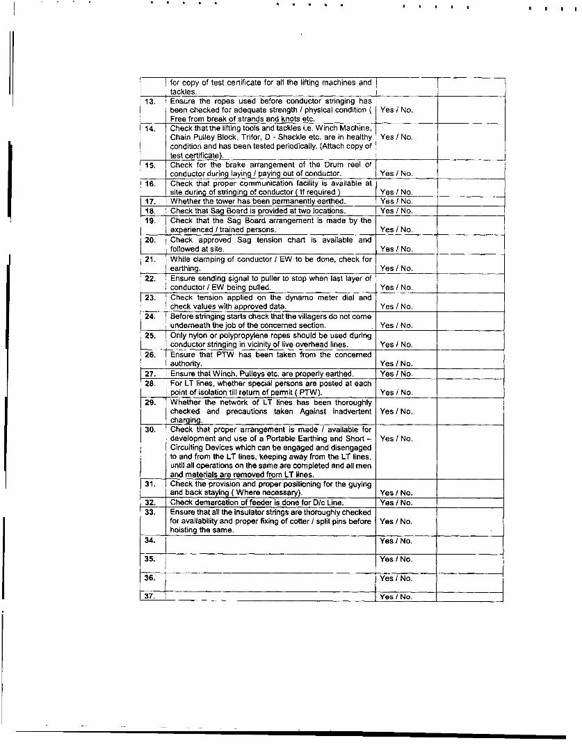
for copy of test certificate for all the lifting machines andtackles.
13. Ensure the ropes used before conductor stringing hasbeen checked for adequate strength I physical condition ( Yes / No.Free from break of strands and knots etc.
14. Check that the lifting tools and tackles i.e. Winch Machine,Chain Pulley Block, Trifor, D - Shackle etc. are in healthy Yes / No.condition and has been tested periodically. (Attach copy oftest certificate). i
15. Check for the brake arrangement of the Drum reel ofconductor during laying I paying out of conductor. Yes / No.
16. Check that proper communication facility is available atsite during of stringing of conductor ( If required ) Yes / No.
17. Whether the tower has been permanently earthed. Yes / No.
18. Check that Sag Board is provided at two locations. Yes / No.
19. Check that the Sag Board arrangement is made by theexperienced / trained persons. Yes / No.
20. Check approved Sag tension chart is available andfollowed at site. Yes / No.
21. While clamping of conductor / EW to be done, check for_____ earthing. Yes / No.
22. Ensure sending signal to puller to stop when last layer ofconductor / EW being pulled. Yes / No.
23. Check tension applied on the dynamo meter dial and
check values with approved data. Yes / No.24. Before stringing starts check that the villagers do not come
underneath the job of the concemed section. Yes / No.
25. | Only nylon or polypropylene ropes should be used during_ conductor stringing in vicinity of live overhead lines. Yes / No.
26. Ensure that PTW has been taken from the concernedauthority. Yes / No.
27. I Ensure that Winch, Pulleys etc. are properly earthed. Yes / No.28. For LT lines, whether special persons are posted at each
____ point of isolation till return of permit ( PTW). Yes / No.29. Whether the network of LT lines has been thoroughly
checked and precautions taken Against inadvertent Yes / No.charging.
30. Check that proper arrangement is made / available fordevelopment and use of a Portable Earthing and Short - Yes / No.Circuiting Devices which can be engaged and disengagedto and from the LT lines, keeping away from the LT lines,until all operations on the same are completed and all menand materials are removed from LT lines.
31. Check the provision and proper positioning for the guyingand back staying (Where necessary). Yes / No.
32. Check demarcation of feeder is done for D/c Line. Yes / No.
33. Ensure that all the insulator strings are thoroughly checkedfor availability and proper fixing of cotter / split pins before Yes / No.hoisting the same.
34. Yes / No.
35. Yes / No.
36. Yes / No.
37. Yes / No.

D. General Points common for all activities during Excavation, Casting of Foundation,Erection of tower and Stringing of Conductor:
SL. Description of Activity Feed back RemarksNO.1. Check whether the contractor had procured required
quantity of PPEs considering maximum numbers of Yes / No.erection gangs deployed at one time. __
2. Supervisors I Workmen have been provided with requiredhealthy PPEs, like Safety helmet I Safety Belts / Safety Yes / No.Shoes / Gum Boot etc. as applicable.
3. Availability of First Aid Box with required medicines at site. Yes / No.4. Instruction register is available at site. Yes / No.5. Ensure that Supervisor / Gang Leader always issues
instruction to the Workmen before start of work. Yes / No.6. Ensure that supervisory staff from Powergrid is available at
site during construction. Yes / No.7. All driver and plant operators are holding valid driving
license. Yes / No.8. Check the vehicle for rescue is available at site. Yes / No.9. Ensure engaged labour are aware of the job. Yes / No.10. Check that the unskilled labourers are not engaged in
skilled job. Yes / No.11. Ensure that supervisor / workmen engaged in the field are
aware of First Aid Techniques ( Such as in case of Electric Yes / No.Shock, Fall from the height, Snake bite and the personrescued from buried under the debris etc.
12. Check for nearby Hospital / Doctor in case of emergenciesarises. Yes / No.
13. While transporting heavy consignment of conductor / EWdrums from central store to site by the use of Cranes, Yes / No.Truck, Tractor. The safety aspect for construction andfailure of brake system of moving machinery is to bechecked.
14. At least one dry powder type of portable fire extinguishershall be provided especially where explosive or blasting Yes / No.agents are used for excavation.
15. Check the competence (Qualification / Experience ) ofsupervisor / gang leader of contractor. Yes / No.
16. Yes / No.17. Yes / No.18. Yes / No.
REMARKS IF ANY:
Signature Signature Signature
Name: Name: Name:Designation: Designation: Designation:Representative of Powergrid Rep. from Site. Powergrid Rep. from RHQ.Contractor _
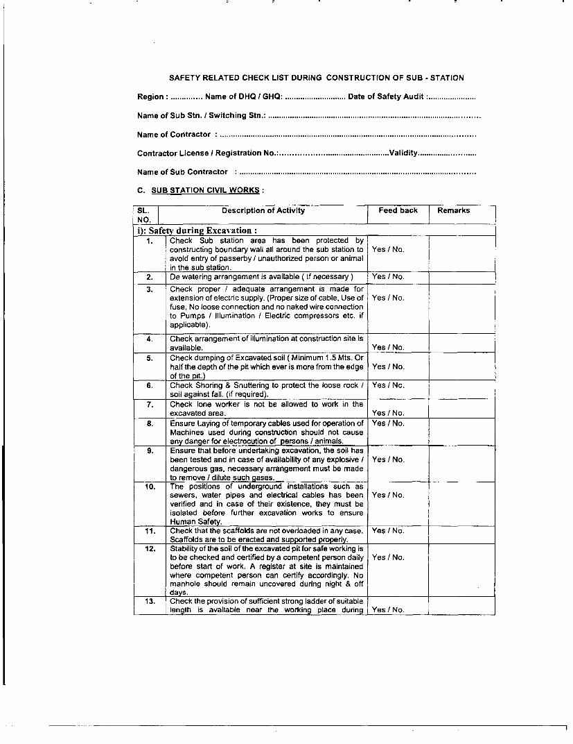
SAFETY RELATED CHECK LIST DURING CONSTRUCTION OF SUB - STATION
Region: ... . Name of DHQ I GHQ: ........ ....... Date of Safety Audit :
Name of Sub Stn. / Switching Stn.:................................................................................................
Name of Contractor : ....................................................................................................................
Contractor License I Registration No.: .................. Validity
Name of Sub Contractor : ...........................................................................................................
C. SUB STATION CIVIL WORKS:
SL.| Description of Activity Feed back RemarksNO.i): Safety during Excavation:
1. Check Sub station area has been protected byconstructing boundary wall all around the sub station to Yes / No.avoid entry of passerby / unauthorized person or animalin the sub station.
2. De watering arrangement is available ( If necessary ) Yes I No.
3. Check proper / adequate arrangement is made forextension of electric supply. (Proper size of cable, Use of Yes / No.fuse, No loose connection and no naked wire connectionto Pumps / Illumination / Electric compressors etc. ifapplicable).
4. Check arrangement of illumination at construction site isavailable. Yes / No.
5. Check dumping of Excavated soil ( Minimum 1.5 Mts. Orhalf the depth of the pit which ever is more from the edge Yes/ No.of the pit.)
6. Check Shoring & Shuttering to protect the loose rock / Yes I No.soil against fall. (if required).
7. Check lone worker is not be allowed to work in theexcavated area. Yes / No.
8. Ensure Laying of temporary cables used for operation of Yes / No.Machines used during construction should not causeany danger for electrocution of persons I animals.
9. Ensure that before undertaking excavation, the soil hasbeen tested and in case of availability of any explosive / Yes / No.dangerous gas, necessary arrangement must be madeto remove / dilute such gases.
10. The positions of underground installations such assewers, water pipes and electrical cables has been Yes / No.verified and in case of their existence, they must beisolated before further excavation works to ensure
IHuman Safety.11. Check that the scaffolds are not overloaded in any case. Yes / No.
Scaffolds are to be erected and supported properly.12. Stability of the soil of the excavated pit for safe working is
to be checked and certified by a competent person daily Yes / No.before start of work. A register at site is maintainedwhere competent person can certify accordingly. Nomanhole should remain uncovered during night & off
IIdays.13. Check the provision of sufficient strong ladder of suitable
|_____ |length is available near the working place during Yes / No.

excavation.14. Check if any permission is required from local statutory
body before excavation. Yes I No.15. Check for No undercutting / toe cutting in soil. Yes / No.16. Check after excavation the work should be speedily
completed without delay and back filling done at the Yes / No.earliest.
17. Check for any possibility of seepage of water fromnearby pond I river has been estimated and taken care Yes I Noof.
18. Check to avoid slide I collaps of side walls of excavatedpit, the excavation is to be done in trapezoidal cross - Yes I No.section.
ii): Safety precaution during Storage, Handling and Use of Blasting Material:
I Check that the adequate arrangement is made for the |storage of blasting material at safe place. (Temporary Yes / No.Magazine is to be installed observing all norms) as perIndian Explosive Act.
2. Check that the blasting materials is handled by licensed Yes I No.blaster with due care at site. (If applicable)
3. Check smoking is prohibited in the vehicle carrying Yes / No.explosives.
4. Check that the Blaster is holding proper license issued Yes I No.by the appropriate authority. As per Indian Explosive Act.
5. Check that the length of the fuse wire used during Yes I No.blasting operation is adequate.
6. Check while transportation, no unauthorized person is Yes / No.allowed in vehicle carrying explosives.
7. Check that the loading and unloading of explosives is Yes I No.being done carefully.
8. Check explosives and detonators or blasting caps is not Yes I No.being transported in the same vehicle.
9. Check while transportation the detonators and Yes I No.explosives are not carried loose or mixed with othermaterials.
10 Check surplus explosives shall not be stacked near Yes / No.working area during loading / unloading.
11. Check explosives shall not be held in hands when Yes / No.lightening the fuse.
12. Check that blasting in the open has been carried out Yes / No.during the fixed hours every day or on fixed days in theweek so that the public at large should know about this.
13. Check that arrangement has been made to display Yes / No.sufficient warnings / sign board to enable the people toget out of the blasting area to get off the danger zone
14. Check that the danger zone has been suitably cordonedoff. Yes I No.
15. Check during blasting operaUons begin I after the firingof explosives shall follow the loud siren. Yes / No.
16. Check that during blasting operation, Labour / Workmen/ Passerby are at safe places and arrangement is made Yes / No.to inform public by caution markings ( Red Flag ) I PublicNotices etc.
17. Check that PPEs i.e. Safety helmets, Safety Shoes, isused by blaster and their gang members during blasting Yes I No.

and also the persons supervising the blasting1 ___ operations.
18. For covered blasting ensure placement of cover platesof proper thickness and sufficient numbers of sand filled Yes I No.
l _____ bags.19. Ensure that permission for blasting has been obtained
from the appropriate authority. Yes / No.20. Yes / No.21. Yes I No.
23. Yes / No.iii) Safety during casting of Foundation I Concreting:
1. Check construction materials are stacked at safe placeand also does not cause any danger.(Away from pit )i.e. Yes / No.1.5 Mtrs. or half the depth of the pit which ever is more.)
2. Check proper arrangement of illumination at ConstructionSite of Sub station is available. Yes / No.
3. Check that the Concreting Mixer/ Vibrator machines etcare placed at a safe place (Not very near to any pit at least Yes / No.1.5 Mtr. from the edge of the pit) to avoid transfer ofvibrations and should be operated by skilled persons.
4. Check proper / adequate arrangement is made forextension of electric supply. (Proper size of cable, Use of Yes / No.fuse, No loose connection for De watering Pumps /Illumination / Electric compressors etc. if applicable).
5. Check for laying of temporary cables used duringconstruction activities should not cause any danger for Yes / No.electrocution to persons / animals.
6. All bracing, struts and shuttering in excavations shall beadequately secured so as to prevent their accidental Yes / No.
_____ displacement.7. Ensure Shuttering and timbering has been made as
detailed in l:S: 3764 for protecting the loose rock / soil Yes / No.against fall.
8. Check for proper placing of Hydraulic jacks with stabilityand constant watch of these instruments (which are Yes / No.continuously loaded) to avoid any danger of displacementcausing sever accident.
9 Yes / No.
190 Yes / No.
B.: Safety during Structure, Equipment Erection & Cable laying etc.:
SL. Description of Activity Feed back RemarksNO.
1. Check Back filling done prior to erection activity. Yes / No.2. Check the derrick used before structure erection has been Test certificate
checked for adequate strength I size and no joints are Yes / No. is requiredpermitted. apart from
visualinspection.
3. Check that the pulleys used before structure erection / TestEquipment Erection has been checked for adequate Yes / No. certificate isstrength I proper size (diameter), also in case of open typepulleys proper locking arrangements like providing of requiredSafety Pin is made Safe working load should be punched. apart from
_____ _________________________________________________ _____________ visual

I _____________ inspection.
4. Check the ropes used before structure erection / Test certificateEquipment Erection has been checked for adequate Yes / No. is requiredstrength / physical condition (free from break of strands apart fromand knots etc. visual________________________________________________ inspectio n .
5. Check that the lifting tools and tackles are in healthy Test certificatecondition and has been tested periodically. Yes I No. is required
apart fromvisualinspection.
6. Check permission has been obtained from AviationAuthority for erection of Lightning Mast which comes in the Yes / No.vicinity of flying zone. (Where necessary )
7. Check that all Nuts and Bolts are fitted in the structurebefore undertaking the job of other section of the structure Yes / No.and are tightened.
8. Check area has been cordoned off to prevent injuries tounauthorized persons from hitting against structural Yes / No.component or falling in the excavated pits.
9. Check that danger plates are available on all theequipment & structures in the switchyard. Yes / No.
10. Check demarcation of feeder is done for Double CircuitLine. Yes / No.
11. Check only erection team members are allowed to standnear the structure / Equipment while erection is in process Yes / No.and should wear the safety helmet / Safety Shoes. ___
12. Check proper guying arrangement has been made whilelifting structure / Equipment, if necessary. Yes / No.
13. Check that proper arrangement is made while lifting thestructure members and fixing them at height. i.e. Proper Yes / No.size and strength of the hook used for lifting the structuremembers.
14. Check sufficient numbers of guys are made while lifting theassembled structure / heavy loads and also avoiding use Yes / No.of single sheeve pulleys while lifting the assembledstructure / heavy load.
15. Check arrangement has been made for equipmentidentification. Yes / No.
16. Check that required painting made on tower falling in thevicinity of aviation zones. ( Where necessary.) Yes / No.
17 Check no live wires nearby. Take shut down if necessary. Yes / No.18. Check the structure has been permanently earthed. Yes / No.19. Check crane are preferably be used for erection of pipe
structure in the sub station building works ( if required.) Yes / No.20. Check all safety procedures for erection work like use of
safety helmets, Safety belts, use of guy wires, lowering / Yes / No.lifting of tools by rope etc. are strictly adhered to duringstructure erection works is in progress in the switchyard. _
21. Check that correct size of spanner (Box or ring type) aswell as DE spanners are being used. Yes / No.
22. Check working area of the structure has been demarcatedduring erection. Yes / No.
23. Check heavy structures are lifted with crane with proper Yes / No.safety.
24. Only polypropylene ropes are to be used to tie theailuminium tube / Bus bar since this is soft material and will Yes / No.not damage alluminium tube I Bus bar during erection.
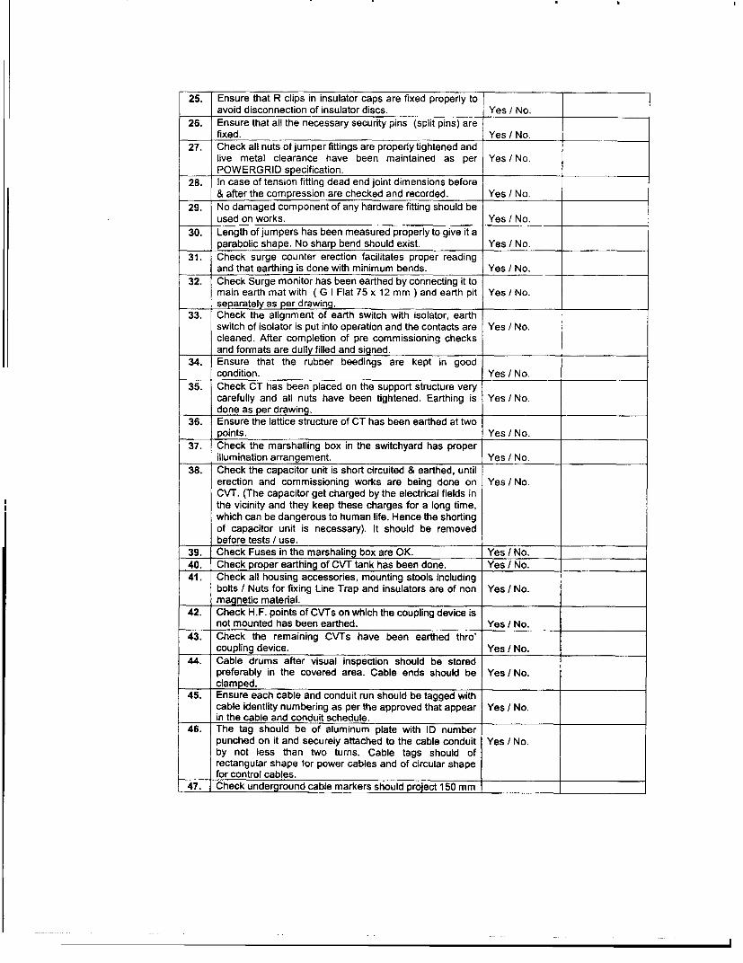
25. Ensure that R clips in insulator caps are fixed properly to 1avoid disconnection of insulator discs. Yes / No.
26. Ensure that all the necessary security pins (split pins) arefixed. Yes / No.
27. Check all nuts of jumper fittings are properly tightened andlive metal clearance have been maintained as per Yes / No.POWERGRID specification.
28. In case of tension fitting dead end joint dimensions before& after the compression are checked and recorded. Yes / No.
29. No damaged component of any hardware fitting should beused on works. Yes / No.
30. Length of jumpers has been measured properly to give it aparabolic shape. No sharp bend should exist. Yes / No.
31. Check surge counter erection facilitates proper readingand that earthing is done with minimum bends. Yes / No. _
I 32. Check Surge monitor has been earthed by connecting it tomain earth mat with ( G I Flat 75 x 12 mm ) and earth pit Yes / No.separately as per drawing.
33. Check the alignment of earth switch with isolator, earthswitch of isolator is put into operation and the contacts are Yes I No.cleaned. After completion of pre commissioning checksand formats are dully filled and signed.
34. Ensure that the rubber beedings are kept in goodcondition. Yes I No.
35. Check CT has been placed on the support structure verycarefully and all nuts have been tightened. Earthing is Yes / No.done as per drawing.
36. Ensure the lattice structure of CT has been earthed at twopoints. Yes / No.
37. Check the marshalling box in the switchyard has properillumination arrangement. Yes / No.
38. Check the capacitor unit is short circuited & earthed, untilerection and commissioning works are being done on Yes / No.CVT. (The capacitor get charged by the electrical fields inthe vicinity and they keep these charges for a long time,which can be dangerous to human life. Hence the shortingof capacitor unit is necessary). It should be removedbefore tests I use.
39. Check Fuses in the marshaling box are OK. Yes / No.40. Check proper earthing of CVT tank has been done. Yes / No.41. Check all housing accessories, mounting stools including
bolts / Nuts for fixing Line Trap and insulators are of non Yes / No.magnetic material.
42. Check H.F. points of CVTs on which the coupling device isnot mounted has been earthed. Yes / No.
43. Check the remaining CVTs have been earthed thro'coupling device. Yes / No.
44. Cable drums after visual inspection should be storedpreferably in the covered area. Cable ends should be Yes I No.
_____ clamped.45. Ensure each cable and conduit run should be tagged with
cable identiity numbering as per the approved that appear Yes / No.in the cable and conduit schedule.
46. The tag should be of aluminum plate with ID numberpunched on it and securely attached to the cable conduit Yes / No.by not less than two turns. Cable tags should ofrectangular shape for power cables and of circular shapefor control cables.
47. Check underground cable markers should project 150 mm _

above ground and spaced at an interval of 30 Mts. They Yes / No.
shall be located on both sides of road and drain crossing.__ and aiso at every change in direction. _
48. Check cable tags should be provided inside the
switchgear, motor control centres, control and relay panels Yes I No.
etc. wherever required for rcable identification, where a
number of cables enter together through a gland plate.
49. The cable (power and control ) between LT station,
Control room, DG set building and fire fighting pump house Yes I No.
should be laid in the buried cable trenches. In addition tothe above, for lighting purpose also, buried cable trench
can be used in outdoor area.( as per Technicalspecification of specific contract )
50. Cable route and joint markers and RCC warning coversshould be provided wherever required. The voltage grade Yes / No.
of cables should be engraved on the marker. _
51. Tray Identification Number on each run of trays at an
interval of 10 Mtrs should be painted. Yes I No.
52. In case the outer sheath of a cable is damaged during
handling / installation, the same should be repaired to the Yes I No.
satisfaction of the site. In case any other part of a cable is
damaged, the same should be replaced by a healthy cable.Power cables should be at the top most layer. The armor of
control cable is to be earthed.53. All cable termination should be appropriately tightened to
ensure secure and reliable connections. All the exposed Yes / No.
parts of cable lugs should be covered with tape, sleeve or
paint.54. Power and control cables are laid on separate cable trays Yes / No. =
55. Co-axial cable is laid separately from power cable. Yes I No.
56. All cable trays, racks and metallic ducts have been
grounded by connecting each to earth I mat. ( As per Yes / No.
Scheme )57. Check sections of cable trays have been bridged by
copper jumpers / G I to retain continuity of earthing. ( As Yes / No.
per Scheme )__ _ _
58. Check earthing of panel is done by the erection contractorfor connecting it with switchyard earth mat. ( As per Yes I No.
Scheme )59. Auxilary bus wiring for AC and DC supplies, Voltage
Transformer circuits, annunciation circuits and other Yes / No.
common services is provided near the top of the panels
running through out the entire length of the panels. _
60. All internal wiring to be connected to external equipment is
terminated on terminal blocks, preferably vertically Yes / No.
mounted on the side of each panel.61. Check whether Mimic Diagram is available preferably
made of anodized alluminium or plastic of approved fast Yes I No.
colour material and screwed on to the panel that can be
easily cleaned.62. Check the panels all equipment mounted on front and rear
side as well as equipment mounted inside are provided Yes / No.
with individual name plates with equipment designated_ engraved.
63. Check on top of each panel on front as well as rear side,
large and bold name plates are provided for circuit I feeder Yes I No.
deslonation.64. Check all front mounted equipments are provided at the
rear with individual name plates engraved with tag Yes I No.
numbers corresponding to panel internal wiring to facilitate l
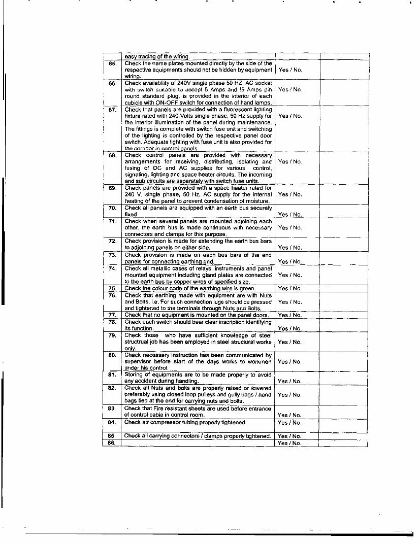
easy tracing of the wiring.65. Check the name plates mounted directly by the side of the
respective equipments should not be hidden by equipment Yes / No._____ wiring.
66. Check availability of 240V single phase 50 HZ, AC socketwith switch suitable to accept 5 Amps and !5 Amps pin Yes I No.round standard plug, is provided in the interior of eachcubicle with ON-OFF switch for connection of hand lamps. l
67. Check that panels are provided with a fluorescent lightingfixture rated with 240 Volts single phase, 50 Hz supply for Yes / No.the interior illumination of the panel during maintenance.The fittings is complete with switch fuse unit and switchingof the lighting is controlled by the respective panel doorswitch. Adequate lighting with fuse unit is also provided forthe corridor in control panels.
68. Check control panels are provided with necessaryarrangements for receiving, distributing, isolating and Yes / No.fusing of DC and AC supplies for various control,signaling, lighting and space heater circuits. The incomingand sub circuits are separately with switch fuse units.
69. Check panels are provided with a space heater rated for240 V, single phase, 50 Hz, AC supply for the internal Yes / No.heating of the panel to prevent condensation of moisture. l
70. Check all panels are equipped with an earth bus securelyfixed Yes / No.
71. Check when several panels are mounted adjoining eachother, the earth bus is made continuous with necessary Yes I No.connectors and clamps for this purpose.
72. Check provision is made for extending the earth bus barsto adjoining panels on either side. Yes / No.
73. Check provision is made on each bus bars of the endpanels for connecting earthing grid. Yes / No.
74. Check all metallic cases of relays, instruments and panelmounted equipment including gland plates are connected Yes / No.to the earth bus by copper wires of specified size.
75. Check the colour code of the earthing wire is green. Yes I No.76. Check that earthing made with equipment are with Nuts
and Bolts. i.e. For such connection lugs should be pressed Yes / No.and tightened to the terminals through Nuts and Bolts.
77. Check that no equipment is mounted on the panel doors. Yes / No.78. Check each switch should bear clear inscription identifying
its function. Yes I No.79. Check those who have sufficient knowledge of steel
structrual job has been employed in steel structural works Yes / No.only.
80. Check necessary instruction has been communicated bysupervisor before start of the days works to workmen Yes / No.under his control.
81. Storing of equipments are to be made properly to avoidany accident during handling. Yes I No.
82. Check all Nuts and bolts are properly raised or loweredpreferably using closed loop pulleys and gully bags / hand Yes / No.bags tied at the end for carrying nuts and bolts.
83. Check that Fire resistant sheets are used before entranceof control cable in control room. Yes / No.
84. Check air compressor tubing properly tightened. Yes / No.
85. Check all carrying connectors / clamps properly tightened. Yes / No.86. Yes / No. _

87. __ Yes / No __ .-
89. _ Yes / No.90. _ Yes / No.
C. Conductor Layout during construction stage:
SL. Description of Activity Feed back RemarksNO. ___
1. Check all members are fixed in structure and ensureproper size of Nuts and Bolts are rigidly tightened and Yes I No.punching I tacking I tack welding is done in towers Istructures before undertaking conductor laying ib.
2. Ensure proper scaffolding arrangements made duringlaying of conductor (While Power Line crossing etc). Yes / No.
3. Ensure that all members are fitted in structure beforeundertaking conductor laying work. Yes I No.
4. Ensure that the discharge rod is electrically tested beforeuse. Yes / No.
5. Ensure whether the structure is properly earthed. Yes I No.6. Only nylon or polypropylene ropes should be used during
conductor laying in vicinity of live overhead lines. Yes I No.
7. Ensure that PTW has been taken from the concernedauthority when extension of existing sub station is under Yes I No.execution.
8. Ensure that Winch, Pulleys etc. are properly earthed. Yes I No.9. For LT lines, check whether special persons are posted at
each point of isolation till return of permit ( PTW) if Yes / No.positioning of person is not possible then it is to be seenthat all the point of isolation has been kept in the lockedposition till the work is in progress.
10. Whether the network of LT lines has been thoroughlychecked and precautions taken against inadvertent Yes I No.charging.
11. Check that proper arrangement is made I available forgrounding LT lines coming across during conductor laying. Yes / No.(This can be done by way of portable earthing and shortcircuiting devices which cab be engaged to anddisengaged from LT lines, keeping away from the LT linesuntil all operations on the same are completed and all manand materials are removed from the LT lines).
12. Check the provision and proper positioning for the guyingand back staying ( Where necessary). Yes / No.
13. Check working of hydraulic crimping machine. Yes / No.14. Check before and after crimping, dimensional changes in
clamps and are in accordance with the drawings and Yes I No.specifications.
15. Yes I No.16. Yes / No.17. Yes I No.18. Yes / No.19. Yes I No.
D: Switchyard Earthing during construction stage:

[SL. Description of Activity Feed back ReakNO.1 Reak
1. Check that while earthing conductor crossing the road islaid 300 mm below the road or at greater depth depending Yes / No.upon the site conditions. _
2. Check that while laying the Earthing conductor in outsidearea is buried at least 600 mm below the furnished ground Yes / No.
l level.3. Check that the earthing pads have been provided for the
apparatus / equipments at accessible position. Yes / No.4. Check all steel columns, metallic stairs are connected to
nearby earthing grid conductor by two earthing leads. Yes / No.5. Check of earthing of lightening fixtures, receptacles
switches, junction boxes lighting conduits has been done Yes / No.by a separate earthing conductor.
6. Check that the railway tracks within switchyard area hasbeen earthed at a spacing of 30 Mts. / specified distance Yes / No.and also at both ends.
7. Check cable trays has been connected to earthing flat of50X6 mm / specified sized earthing flat at intervals Yes / No.
i__I_ specified in approved drawing. _8. Check that this earthed flat is earthed at about 30 Mts.
distance. Yes / No.9. All accessories in transformer and reactor like radiators
tank, cooling banks etc are connected to the earthing grid Yes / No.at minimum two points.
10. Check metallic conduits are not used as earth continuityconductor. Yes / No.
11. Check flexible earthing connectors should be provided forthe moving parts. Yes / No.
12. Check sheath and armor of single core power cable isearthed at switchgear end and equipment side. Yes I No.
13. Check contact surface of earthing pads for jointing freefrom scale, paint, enamel, grease, rust or dust. Yes I No.
14. Check that light poles, junction boxes on the poles, cableand cable boxes / glands, lockout switches etc. are Yes / No.connected to the earthing conductor running along with thesupply cable which intern is connected to the earthing gridconductor at a minimum two points.Check earthing conductor which is generally buried 2000
15. mm outside the switchyard fence. All the gates and every Yes / No.alternate post of the fence is be connected to earthing grid.Check megger used for measuring soil resistivity is
16. calibrated with desired accuracy. Yes / No.The earth resistivity has been measured in dry weather
17. condition. Yes / No.Check the earthing of Transformers and Shunt reactor,
18. earth pits are constructed as per relevant standard / Yes / No.approved drawing.Check that the measured value of combined earth
19. resistance should be less than 1 Ohm. Yes / No.l Check that for earth electrode and individual earth pits, this
20. value should not be more than one Ohm. Yes / No.Check all non current carrying metal parts shall be
21. effectively earthed by two separate and distinct earth Yes I No.connections ( Indian Electricity Rule 61, 67)
22. j Check that all pylon supports in the Fire Fighting HVSW I
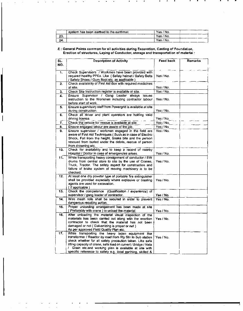
system has been earthed to the earthmat. Yes / No.23. Yes / No.24. _ _ . Yes / No.
E : General Points common for all activities during Excavation, Casting of Foundation,Erection of structures, Laying of Conductor, storage and transportation of material:
SL. Description of Activity Feed back RemarksNO.
1. Check Supervisors / Workmen have been provided withrequired healthy PPEs. Like ( Safety helmet I Safety Belts Yes / No./ Safety Shoes / Gum Boot etc. as applicable )
2. Check availability of First Aid Box with required medicinesat site. Yes / No.
3. Check Site Instruction register is available at site. Yes / No.4. Ensure Supervisor / Gang Leader always issues
instruction to the Workmen including contractor labour Yes/ No.before start of work.
5. Ensure supervisory staff from Powergrid is available at siteduring construction. Yes I No.
6. Check all driver and plant operators are holding validdriving license. Yes I No.
7. Check the vehicle for rescue is available at site. Yes I No.8. Ensure engaged labour are aware of the job. Yes I No9. Ensure supervisor / workmen engaged in the field are Yes / No.
aware of First Aid Techniques ( Such as in case of ElectricShock, Fall from the height, Snake bite and the personrescued from buried under the debris, rescue of personfrom drowning etc.
10. Check for availability and to keep a record of nearbyHospital / Doctor in case of emergencies arises. Yes / No.
11. While transporting heavy consignment of conductor / EWdrums from central store to site by the use of Cranes, Yes / No.Truck, Tractor. The safety aspect for construction andfailure of brake system of moving machinery is to bechecked.
12. At least one dry powder type of portable fire extinguishershall be provided especially where explosive or blasting Yes / No.agents are used for excavation.( If applicable )
13. Check the competence (Qualification / experience) ofsupervisor / gang leader of contractor. Yes / No.
14. Wire mesh rolls shall be secured in order to prevent Yes / No.dangerous recoiling action.
15. Proper unloading arrangement has been made at site( Preferably with crane ) to unload the material. Yes / No.
16. After unloading the material visual inspection of thematerials has been carried out along with the erection Yes / No.contractor to check that the material has not beendamaged or not ( Galvanizing is proper or not)As per approved Field Quality Plan etc.
17. While transporting the heavy laden equipment liketransformer / Reactor by road from Rly Stn to Sub station Yes / No.check whether for all safety precaution taken. Like safelifting capacity of crane, safe load on culvert / Bridge / NalaI Drain etc.and working plan is available at site withspecific reference to safety e.g. local earthing, skilled & I
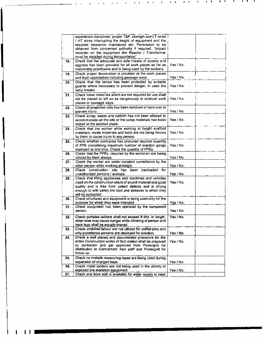
experience manpower, proper T&P, strength and LT wires/ HT wires interrupting the height of equipment and therequired clearance maintained etc. Permission to beobtained from concerned authority if required. "Impactrecorder on the equipment like Reactor / Transformermust be installed during transportation"
18. Check that the adequate and safe means of access andaggress has been provided for all work places as far as Yes / No.reasonably practicable and is being used by the workers.19. Check proper illumination is provided at the work placesand their approaches including passage ways. Yes / No.20. Check that the lamps has been protected by suitableguards where necessary to prevent danger, in case the Yes / No.lamp breaks.21. Check loose materials which are not required for use shallnot be placed or left so as dangerously to obstruct work Yes / No.places or passage ways.22. Check all projected nails has been removed or bent over to
prevent injury. Yes / No.23. Check scrap, waste and rubbish has not been allowed toaccommodate on the site or the scrap materials has been Yes / No.stored at the isolated place.24. Check that the worker while working at height scaffoldmaterials, waste materials and tools are not being thrown Yes I No.by them to cause injury to any person.25. Check whether contractor has procured required quantityof PPE considering maximum number of erection gangs. Yes / No.deployed at one time. Check the quantity of PPEs.26. Check that the PPEs. required by the workmen are being
utilized by them always. Yes / No.27. Check the worker are under constant surveillance by theother person while working at height. Yes / No.28. Check construction site has been barricaded forunauthorized persons / animals. Yes / No.29. Check that lifting appliances and machines and vehiclesused on the construction site is of sound material and good Yes / No.quality and is free from patent defects and is strongenough to with safely the load and stresses to which theywill be subjected .
30. Check struetures and equipment is being used only for thepurpose for which they were intended. Yes / No.31. Check equipment has been operated by the competentperson. Yes / No.
32. Check portable ladders shall not exceed 9 Mts. in length, Yes / No.other wise may cause danger while climbing of person andback legs shall be equally braced.
33. Check unskilled labour are not utilized for skilled jobs andonly experience persons are deployed for erection. Yes / No.34. Check a well planed and documented procedure for theentire Construction works of Sub station shall be prepared Yes / No.by contractor and get approved from Powergrid fordistribution to Contractors' field staff and Powergrid forfollow up.
35. Check no metallic measuring tapes are being used duringexpansion of charged bays. Yes / No.36. Check metal ladders are not being used in the vicinity ofexposed live electrical equipment. Yes / No.37. Check one bore well is available for water supply in case
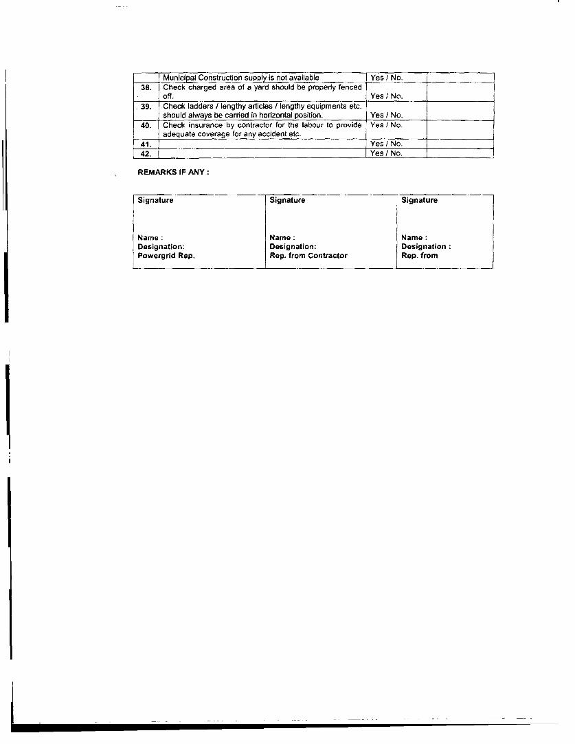
Municipal Construction supply is not available Yes / No. l38. Check charged area of a yard should be properly fencedYe No
.off. Yes I No..39. Check ladders / lengthy articles / lengthy equipments etc.
should always be carried in horizontal position. Yes / No.40. Check insurance by contractor for the labour to provide Yes / No.
adequate coverage for any accident etc.l41. Yes / No.42. Yes/N _No
REMARKS IF ANY:
Signature Signature Signature
Name: Name: Name:Designation: Designation: DesignationPowergrid Rep. Rep. from Contractor Rep. from

ANNEXURE- 3
PUBLIC NOTICE

~1Ti- "41T3T-* '. fRit~I - 28.09.2004, - tqYtT- 03.00cTd
9qjcqfz, gM f9iTtF 765' ic.e. f#*-4M- 1v,S
cit olvi41, Y1940, tf, q '191r, AgleT, fx, M M, 4 41,
-<jqd, q1aE1,< ,rc t4jRj -jq-4,, 4SAl.,j ,alll ,r-cT 4qr, JM94,Th-TTV, Mlc4'11<g Oct41,acq4l,~lWifiZ cliaci, 4WR9t, U,ft qt, t11,
. HtVT 0em tAhz Pf¢s .l+n , *-ip Wq<1AEim 01409 T wiqyv-f14
arPT,, I
ftM 460 661

ANNEXURE - 4
PAMPHLET
5 ~ ~ ~ ~
-T T4u fullA q'11911 765 *.. f\qq-AT w1o
gfW WRtv -IqT * *f Th4 IdM0 W AW WN 134fER # t-4"u v7ye,~ ~~~~m 'MamW ** *w oh w *; Ng
lilmW t I MV1*;T !tj qjllt , RwTqF r aWr i-li
T&qi * qitfAS aM%M 48,000 f*.*. #W \ w W r Wgrdiw W r t ar rn* 82't'i*¢t - iQqd;tq ^M 4A,5oo MVA tl I
Elf/ )7yT 1v?I RmY- Wron q Aclint f4o * A"* *1980 MW* 1 c w4hR4 W t I I 5 w4ifa w * f qIWFq,Tr 1500 &A;. fW. r w * *Iur RI -auW4WZW tF I 'M 1Wq * % ,01%, 4q/m -$7It Wfv17T ?r IIU #Wm qRugI * P 765 *q f4br imu t tIa4z1Xi?h mR4 0 * rfft AoR * 4 W a& MkS 7W itn7AM ti'iif wy& Wm*uq'w4 1T t 1 76s ti*. Tfl4*m 60q iwTj6W: f4, 1,R Rltt14, Mt, li1x4141, WMqoc>, 14rft, \n!p "f.,slxa-irtl wvt, piva , tM, , qCjj .# OM, JW.M f4if gjjd$j qll(4.ffq.
-aM4I. , qVIXIQ, IW'"1M9 ,on,Aq1l.ww
WU *T-W gu8 flepr 41M Wi *t 4f4'l-n 69 Q$AAM- *t IPR " Nu4mlf!$ vt I mwq9 es< 04mQhlnl iS qal, *4 *' W'f 4 M* W00 -W*91'800 4VjFC #Mf * q4M; f. fb* n MtV W*) # * ttsUf a
*7i 7;S WW Wff 1kW ;= Wfl I 1~f 4N MQq11 * 'POM10 ,tc qwlawil htWm>

MAP-1
FOREST COVER MAP OFMADHYA PRADESH

Bhi-k \
RAJAST, HAN /T~ UT'TAR PRADESH
ati~~~~~~San
'lJ,iar 'f A
~~~~~~~~~~~~~~~~~~~~~~~~~~~'4;H S drGA9P
-~~~~~~~~~~~~Ai ,- )6. i :-
-7. ... ......
Q.'ier bire i
, . v ' c r 'cr- u
,,, ~~~~~~~~~~~~~~ t^.~~~~~~~~~~ater-bcjles
- -~~~~~~~~~~~~~~~~~- ~~~~~~~State ocJnoar;
Forest Cover Map of Madhya Pradesh
l l~~~~~~~~~~~~~~~~~~~~~~~~~~~~~~~~~~~~~~~~~oao
MAP-2
ALTERNATIVE ROUTE ALIGNMENTSOF
765 KV S/C SEONI - BINA LINE
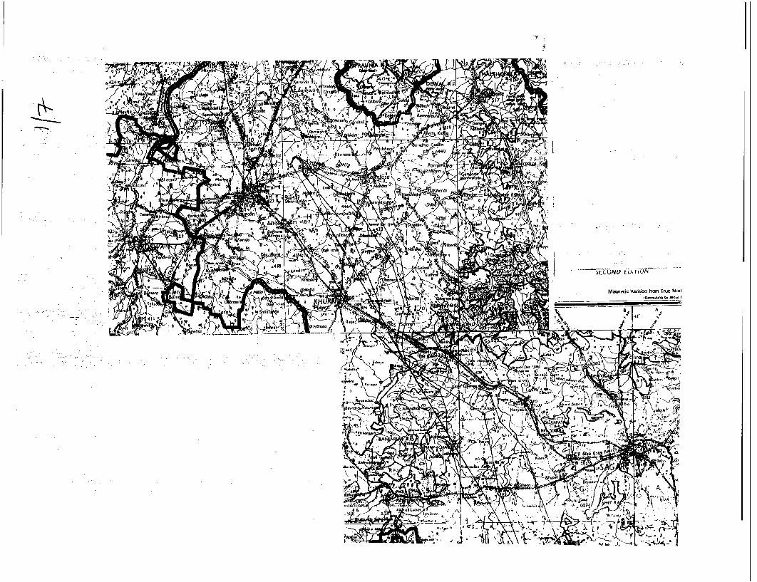
of '~~~~~~~~~~~~~O
vV~~~~~~~~~~~~~~~~~~~~~~~~~~~~~~~~~~~~~~~~~~~~~~~~~~~~v
Magnedc Yaridon from tlue No.1
- w . -A4
.0~1'ThYUt% 4C'

1113~~~~~~~~~~~~~~~~~~~~~tUU~)10
~~~W~~~~~t '' 1~~~~~~~~~~~~~~~o 5
~~~~~~~~~~~~~~~~N l
4.,,
,, . .
t~~~~~~~~~~~~~~~~~~ tFS
q: ~ F ~ '4d..~
(ft ~~~~~~~~~~~~~~ ~~~ ~3-
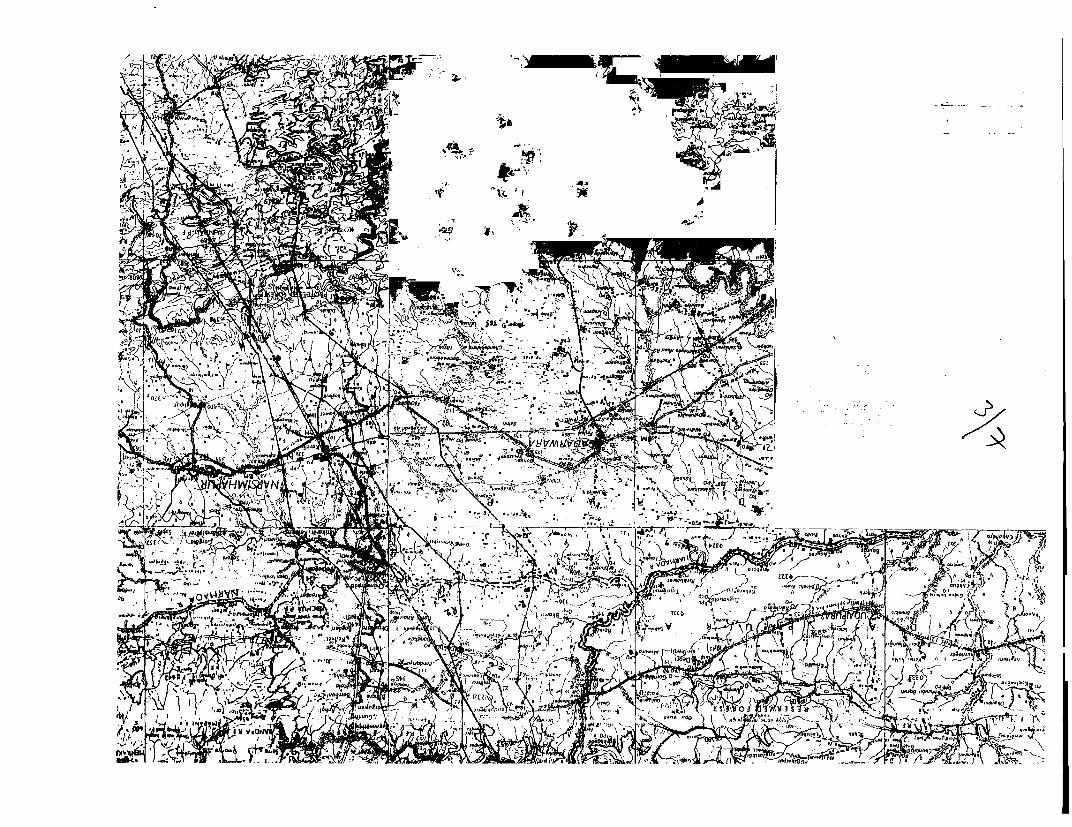
14W~~~~~~~~W
'_7~~~~~~~~~~
,61 ~ ~ ~ ~ ~ ~ ~ ~ ~ ~ KLk~ ~ ~ ~ ~~A
oqit / p - 4-MI

arc~~~~~~~~~~~~~~r
S er g ¢ 1(71

'~~ '--r)J, -
(7 VIVIV~~~~~~~~-N Aeb'S

. I s~~~~~~~~~~~~~~~~~~~~~a,
F ~ ~ ~ ~ ~ ~ ~ ~ ~ ~ ~ -4 **A
'4~~~~~~~~~~~~~~~~~~~~~~~~~~~~~~~~7-v4 .
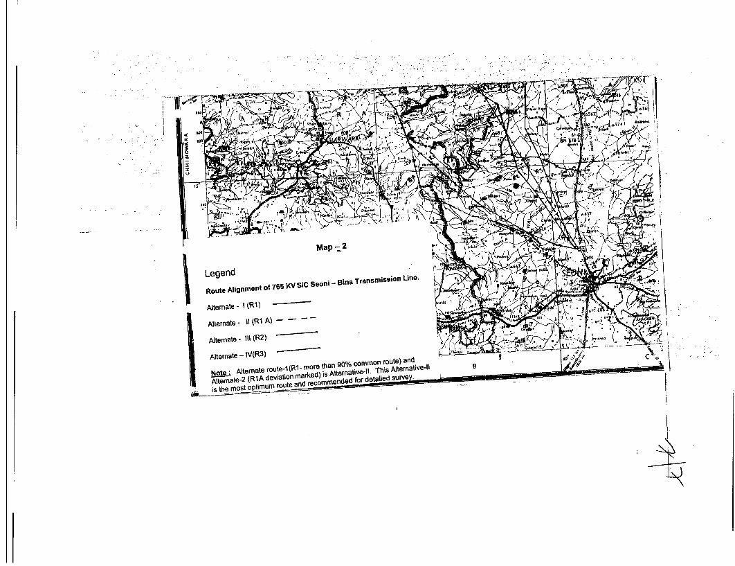
map -- 2 ~ ~ ~ ~ ~ ~~K
:'~~~~~~~~~~~~~~~~~~~~~~~~~~~~~~~~~~~~~~~~~~~~~~~~~~~'
Alternate- I (RI) -
Alternate - III (Ri2)
Alternate- IV(R3) =
Asthe mate- R o evtimu r at and recomm ended for detailed surve

PLATE 1-2
PUBLIC CONSULTATION

PLATE-1
.- -- t
-d~~~~~~AA>-c~~~~~~~~~~~v
-- ir t \ it i '7a -- e
PUBLIC MEETING AT VILLAGE HARRI

5 w~~it 'I' ', A
-lw w~~~~~~~~~~~~~-
-eF~~~~~~~~~~~-
f~t 1a. Eu |w
N ~~~~~w
if'' 7' 0 a' wv,
LU
- , ,,, . a- ) A We 'Kri
FIGURE-1
l~~~ -
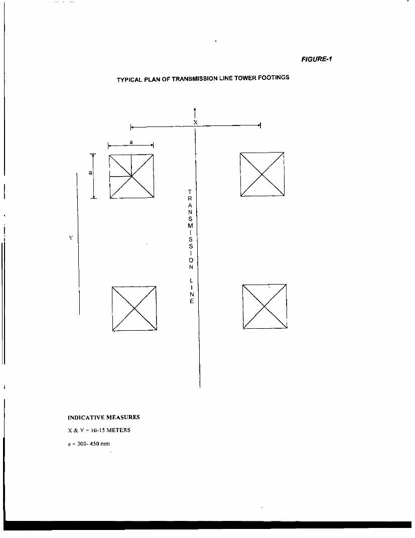
FIGURE-1
TYPICAL PLAN OF TRANSMISSION LINE TOWER FOOTINGS
I x bl~~~~~
Y~~~~i S
RANSM
0
N
L
N
E
INDICATIVE MEASURES
X & Y = 10-15 METERS
a = 300- 450 mm