infrastructure design criteria - village of penn yan, ny€¦ · infrastructure design criteria and...
TRANSCRIPT

Infrastructure Design Criteria
and
Construction Specifications
Village of Penn Yan
Penn Yan, New York
February2017
Adopted March 2017

THIS PAGE INTENTIONALLY BLANK
i
Table of Contents
Page Glossary .............................................................................................................. xi Introduction ..............................................................................................................xv Section 1 General Requirements ......................................................................................................1
1.1 Sequence of Procedures - General..................................................................1 Section 2 Sequence of Procedures ...................................................................................................1
2.1 Pre-Application ..............................................................................................1
2.2 Minor versus a Major Subdivision of Land ...................................................1 2.3 Sketch Plan Review ........................................................................................1 2.4 Preliminary Plan Review ................................................................................2
2.5 Final Plan Review ..........................................................................................3 2.6 Special Improvement Districts .......................................................................4 2.7 Easements .......................................................................................................4
2.8 Acceptance of Land to be Dedicated ..............................................................4 2.9 Irrevocable Letter of Credit ............................................................................5
A. Water Distribution System .................................................................5 B. Sanitary Sewer System .......................................................................5 C. Storm Water Collection System .........................................................6
D. Roadways ...........................................................................................6 E. Grading and Erosion Control .............................................................6
F. Miscellaneous .....................................................................................6 G. Five percent (5%) Village inspection fee on total of items A to F .....6
2.10 Preparation of Record Plans ...........................................................................8 2.11 Approval of Completed Works and Maintenance Bond ................................8
2.12 Release of Warranty .......................................................................................8 2.13 Preconstruction Meeting ................................................................................9 2.14 Areas of Responsibility ..................................................................................9
A. Clerk Treasurer and Village Board ....................................................9 B. Planning Board ...................................................................................9
C. Director of Public Works, Police Chief, Fire Chief and Engineer ...10 D. Attorney ............................................................................................10
E. Village Department Heads for Streets, Water, Sewer & Electric ....10 F. New York State Department of Health .............................................10 G. New York State Department of Environmental Conservation .........10
Section 3 General Design Requirements .......................................................................................13 3.1 General .........................................................................................................13 3.2 Basis of Design, General ..............................................................................13 3.3 Submission of Plans and Pertinent Data ......................................................13
A. Engineer’s Report .............................................................................13 B. Required Drawings ...........................................................................14
Section 4 Road, Street, and Pavement ...........................................................................................19 4.1 General .........................................................................................................19 4.2 Basis of Design, General ..............................................................................19 4.3 Proper Design ...............................................................................................19
ii
4.4 Street Arrangement ......................................................................................19 4.5 Temporary Dead-end Streets ........................................................................20 4.6 Standards for Street Design ..........................................................................21 4.7 Street Intersections .......................................................................................21
4.8 Street Grading and Shoulders .......................................................................22 4.9 Sidewalks .....................................................................................................23 4.10 Trees .............................................................................................................23 4.11 Street Names and Signs ................................................................................23 4.12 Monuments ...................................................................................................23
4.13 Street Improvements - General.....................................................................24 A. Widening of Existing Street Right-of-Way ......................................24
4.14 Road Sections ...............................................................................................24
4.15 Non-Residential Subdivisions ......................................................................24 4.16 Highway Frontage ........................................................................................25 4.17 Private Drives ...............................................................................................25
Section 5 Storm Drainage Facilities ..............................................................................................27 5.1 General .........................................................................................................27
5.2 Basis of Design, General ..............................................................................27 5.3 Proper Design ...............................................................................................27 5.4 Submission of Plans and Pertinent Data ......................................................27
A. Basis of Design Report .....................................................................27 B. Plans and Support Documents ..........................................................28
5.5 Purpose and Intent ........................................................................................29 5.6 General Requirements ..................................................................................30
5.7 Design of Drainage Systems ........................................................................31 A. Hydrologic ........................................................................................31
B. Hydraulic ..........................................................................................35 C. Criteria ..............................................................................................36 D. Stormwater Detention Basins ...........................................................37
5.8 Erosion and Sedimentation Control .............................................................39 5.9 Water Quality ...............................................................................................39
5.10 Drainage Easements .....................................................................................39 5.11 Flood Hazard Prevention ..............................................................................40
Section 6 Sanitary Sewage Facilities .............................................................................................41 6.1 General .........................................................................................................41 6.2 Basis of Design, General ..............................................................................41
6.3 Proper Design ...............................................................................................41 6.4 Submission of Plans and Pertinent Data ......................................................41
A. Basis of Design Report .....................................................................41 B. Plans and Support Documents ..........................................................42
6.5 Design of Sewers ..........................................................................................44 A. Details of Gravity Pipe Design .........................................................44 B. Details of Pressure Pipe Design .......................................................49 C. Details of Manhole Design ...............................................................51 D. Inverted Siphons ...............................................................................52 E. Location of Sewers in Streams .........................................................52
iii
F. Protection of Water Supplies ............................................................53 G. Design of Wastewater Pumping Stations .........................................55 H. Suction Lift Pump Stations ..............................................................59 I. Alarm Systems .................................................................................61
J. Emergency Operation .......................................................................61 Section 7 Water Supply ..............................................................................................................65
7.1 General .........................................................................................................65 7.2 Basis of Design, General ..............................................................................65 7.3 Proper Design ...............................................................................................65
7.4 Submission of Plans and Pertinent Data ......................................................66 A. Engineer’s Report .............................................................................66 B. Plans And Support Documents ........................................................67
C. Revisions To Approved Plans ..........................................................67 D. Additional Information Required .....................................................67
7.5 Design of Water Mains ................................................................................67
A. Public Water System Design Standards ...........................................67 B. Materials for Water Mains and Services ..........................................68
Section 8 Municipal Electric ..........................................................................................................71 8.1 Territory To Which Schedule Applies .........................................................71 8.2 Definitions Applicable .................................................................................71
8.3 Service May Be Obtained ............................................................................71 8.4 Metering .......................................................................................................72
A. Multiple Service ...............................................................................72 B. Master Meter of Submetering...........................................................72
C. Temporary Service Connection ........................................................73 D. Mixed Occupancy Classification......................................................73
E. Municipal Property ...........................................................................73 F. Access to Premises ...........................................................................73 G. Right-of-Way ...................................................................................74
H. Limitation of Use .............................................................................74 8.5 Service Entrance Requirements ...................................................................74
A. Residential ........................................................................................74 B. Apartmental ......................................................................................74
C. Outdoor Meters ................................................................................75 D. Point of Service ................................................................................75 E. Primary Metered Service ..................................................................75
F. Service Laterals ................................................................................75 G. Underground Service – Residential Subdivisions, Commercial and/or Industrial customers ........................................................................76
8.6 Extension of Lines ........................................................................................77
A. Contribution for Extensions .............................................................77 B. Surcharge Agreement .......................................................................77 C. Surcharge Period ..............................................................................78
Section 9 Miscellaneous ..............................................................................................................79 9.1 Accommodations for House and Lot Storm Drainage .................................79 9.2 Easements .....................................................................................................79
iv
Section 10 General Construction Requirements ............................................................................81 10.1 General .........................................................................................................81
A. Purpose .............................................................................................81 B. Inspection .........................................................................................81
C. Responsibility for Work ...................................................................81 D. Safeguarding Existing Utilities, Other Property and Persons ..........81 E. Warranty of Work and Materials .....................................................82 F. Stakeout ............................................................................................82 G. Protection of Incomplete Works ......................................................82
H. Final Drawings .................................................................................82 I. Full Completion of Work and Cleanup ............................................83 J. Permits ..............................................................................................83
Section 11 Road, Street, and Pavement .........................................................................................85 11.1 Materials - General Requirements ................................................................85 11.2 Basis of Construction ...................................................................................85
11.3 Roadway Excavation ....................................................................................86 11.4 Preparing Road Subgrade .............................................................................86
A. Work .................................................................................................86 B. Method .............................................................................................86
11.5 Road Base .....................................................................................................88
A. Work .................................................................................................88 B. Material ............................................................................................88
C. Method .............................................................................................88 11.6 Granite Curbing ............................................................................................89
A. Work .................................................................................................89 B. Material ............................................................................................89
C. Method .............................................................................................89 11.7 Construction of Concrete Gutters .................................................................89
A. Work .................................................................................................89
B. Material ............................................................................................89 C. Method .............................................................................................90
D. Cold Weather Concreting .................................................................91 E. Wet Weather Concreting ..................................................................91
F. Curing ...............................................................................................91 11.8 Bituminous Concrete Pavement ...................................................................92
A. Work .................................................................................................92
B. Material ............................................................................................92 C. Method .............................................................................................92
11.9 Double Bituminous Surface Treatment (Private Drives Only) ....................93 A. Work .................................................................................................93
B. Materials ...........................................................................................93 C. Method .............................................................................................93
11.10 Maintenance of Roadway .............................................................................95 11.11 Temporary Turnarounds ...............................................................................96 11.12 Private Drives ...............................................................................................96
A. Other Than Single Family Driveways ..............................................96

v
11.13 Single Family Driveways .............................................................................97 Section 12 Storm Drainage ............................................................................................................99
12.1 Catch Basin Construction .............................................................................99 A. Work .................................................................................................99
B. Material ............................................................................................99 C. Method .............................................................................................99
12.2 Construction of Storm Drains ....................................................................100 A. Storm Water Sewer Pipe ................................................................100 B. Special Construction ......................................................................100
C. Manholes and Catch Basins ...........................................................100 D. Special Structures ...........................................................................100 E. Handling Pipe .................................................................................100
F. Stockpiling Pipe .............................................................................101 G. Fitting and Cutting Pipe .................................................................101 H. Joints ...............................................................................................101
I. Line and Grade ...............................................................................101 J. Trenches .........................................................................................101
K. Barricades .......................................................................................101 L. Spoil ...............................................................................................101 M. Drainage .........................................................................................102
N. Pipe Installation ..............................................................................102 O. Earth Foundation ............................................................................102
P. Bedding - Hand Backfilling ...........................................................102 Q. Backfill ...........................................................................................103
R. Cradle .............................................................................................103 S. Protection of Existing Sewers ........................................................103
T. Protection of New Work ................................................................103 U. Construction Under Adverse Conditions .......................................103 V. Conflicting Pipe Lines & Other Utilities ........................................104
W. House Laterals ................................................................................104 Section 13 Sanitary Sewer Facilities ............................................................................................105
13.1 Gravity Sewer .............................................................................................105 A. Pipe Installation ..............................................................................105
B. Backfill ...........................................................................................107 C. Installation of Ductile Iron, and PVC Pipe - General.....................116 D. Lateral Construction .......................................................................118
E. Construction of Sewers Crossing Streams .....................................119 F. Testing of Sanitary Sewers and Appurtenances .............................119 G. Video Taping Sanitary Sewer System ............................................121
13.2 Pressure Sewer Pipe Installation ................................................................122
A. General ...........................................................................................122 B. Bedding and Backfill ......................................................................123 C. Testing – Sewer Force Mains .........................................................123
13.3 Manhole Installation ...................................................................................124 A. Precast Circular Manhole Sections ................................................124 B. Joints ...............................................................................................125
vi
C. Manhole Steps ................................................................................125 D. Brick ...............................................................................................126 E. Mortar .............................................................................................126 F. Hydraulic Cement ..........................................................................126
G. Manhole Covers, Grates, and Frames ............................................126 H. Sanitary Pipe Connections to New Manholes ................................127 I. Concrete Bench Walls/Cast-in-Place Concrete ..............................127 J. Cleanout Frame and Cover .............................................................128 K. Orientation of Covers, Grates, and Rungs ......................................128
L. Construction of New Manholes and Structures ..............................129 M. Connection to Existing Sanitary Manholes ....................................130 N. Installation of Precast Manholes ....................................................130
O. Testing ............................................................................................130 P. Rejection and Repair ......................................................................131 Q. Marking and Painting .....................................................................132
Section 14 Water Supply ............................................................................................................133 14.1 Water Mains and Appurtenances ...............................................................133
A. Excavation, Grading, and Shoring .................................................133 B. Storage and Handling .....................................................................133 C. Job Conditions ................................................................................133
D. Methods Of Control For Excavations And Grading ......................134 E. Limit Of Excavation For Pipelines .................................................134
F. Limit Of Excavation For Structures ...............................................134 G. Site Grading ....................................................................................134
H. Storage Of Materials ......................................................................134 14.2 Pipe and Structure Backfill ........................................................................135
A. General ...........................................................................................135 B. General Backfilling Requirements .................................................136 C. Settlement .......................................................................................136
14.3 Installation of Water Mains and Appurtenances ........................................136 A. Handling Materials .........................................................................136
B. Laying Pipe ....................................................................................137 C. Cutting Pipe ....................................................................................137
D. Permissible Deflection at Joints .....................................................137 E. Making Joints .................................................................................137 F. Installing Fittings and Valves .........................................................137
G. Setting Hydrant Units .....................................................................138 H. Painting ...........................................................................................138 I. Connection to Existing Mains ........................................................138 J. Special Requirements for Protection of Water Mains ....................138
K. Anchorage and Blocking ................................................................139 L. Repairs ............................................................................................140
14.4 Installation of Water Services ....................................................................140 A. General ...........................................................................................140 B. Preparation of Bed ..........................................................................140 C. Installing Water Services ...............................................................140
vii
D. Corporation Stop Installation .........................................................140 E. Installing Curb Stops and Curb Boxes ...........................................140 F. Crossing Under Pavement ..............................................................141
14.5 Preparation for Use .....................................................................................141
A. Water Supply ..................................................................................141 B. Flushing ..........................................................................................141 C. Testing Water Mains and Hydrant Units ........................................141 D. Testing Services .............................................................................142 E. Disinfection ....................................................................................142
Section 15 Electrical Construction...............................................................................................143 15.1 Electrical Installations ................................................................................143 15.2 Excavation, Installation and Backfill Requirements ..................................143
A. General ...........................................................................................143 B. Excavation ......................................................................................143 C. Installation ......................................................................................144
D. Backfill ...........................................................................................144 E. Inspection .......................................................................................144
F. Appurtenances ................................................................................144 G. Distribution System Maintenance ..................................................145
15.3 Services ......................................................................................................146
A. Building Installations .....................................................................146 B. Metering .........................................................................................147
C. Trailer Park Installations ................................................................147 15.4 Lighting ......................................................................................................147
A. General ...........................................................................................147 B. Materials .........................................................................................147
C. Guarantee .......................................................................................148 D. Site Location ..................................................................................148
Section 16 Miscellaneous Construction .......................................................................................149
16.1 General Grading, Trimming, Seeding, and Related Work .........................149 A. General ...........................................................................................149
B. Establishment of Turf .....................................................................149 C. Procedure ........................................................................................150
D. Maintenance ...................................................................................152 E. Guarantee .......................................................................................152
16.2 Trees ...........................................................................................................152
A. Existing Tree and Plant Material ....................................................152 B. New Trees ......................................................................................152 C. Street Trees .....................................................................................153 D. Replacement ...................................................................................153
E. Final Inspection and Final Acceptance ..........................................154 16.3 Portland Cement Concrete Sidewalk ..........................................................154
A. General ...........................................................................................154 B. Materials .........................................................................................154 C. Concrete Mixing .............................................................................156 D. Subgrade Preparation .....................................................................157
viii
E. Crushed Stone Base ........................................................................157 F. Form Work And Concrete Placement ............................................157 G. Finishing And Curing .....................................................................158 H. Joints ...............................................................................................158
I. Convenience of Property Owners ..................................................158 J. Testing ............................................................................................159 K. Batching .........................................................................................159 L. Final Trim, Seeding, and Clean-up ................................................159
16.4 Sediment and Dust Control ........................................................................159
A. General ...........................................................................................159 B. Sequence of Work ..........................................................................159 C. Scope of Facilities ..........................................................................159
D. Performance ...................................................................................160 E. Ancillary Sediment Control Features .............................................160 F. Termination of Facilities ................................................................161
G. Dust and Mud Control ....................................................................161 LIST OF TABLES TABLE 1 STANDARDS FOR STREET DESIGN .......................................................................... 22 TABLE 2 RUNOFF COEEFFICIENTS FOR VARIOUS SURFACES ........................................... 33 TABLE 3 APPLICATION RATES ................................................................................................... 95 TABLE 4 COARSE AGGREGATE GRADATIONS .................................................................... 154 TABLE 5 CONCRETE MIX CRITERIA ....................................................................................... 156 LIST OF FIGURES
FIGURE 1 Rainfall Intensity ..............................................................................................34 FIGURE 2 Rainfall Intensity Curves .................................................................................34 APPENDICES
APPENDIX A IRREVOCABLE LETTER OF CREDIT APPENDIX B ENGINEER’S ESTIMATE OF PROBABLE COST FOR LETTER OF CREDIT APPENDIX C SAMPLE STATEMENT OF COMPLETED CONSTRUCTION
ix
STANDARD DETAILS Miscellaneous Details DRAWING M-01 SANITARY SEWER / WATER MAIN CROSSING DRAWING M-02 PIPE TRENCH DETAILS DRAWING M-03 ROAD, DRIVEWAY AND SHOULDER REPLACEMENT DETAILS DRAWING M-04 TREE PLANTING DRAWING M-05 TREE SUPPORT AND SHRUB PLANTING DRAWING M-06 STREET TREE AND SIDEWALK GREEN SPACE DRAWING M-07 TYPICAL STEEL CASING PIPE DRAWING M-08 TYPICAL BORING PIT DRAWING M-09 ROAD BORE CROSSING PROFILE DRAWING M-10 BOLLARD DETAIL Erosion Control Details DRAWING R-01 SILT FENCE DRAWING R-02 STRAW BALE DIKE DRAWING R-03 STABILIZED CONSTRUCTION ENTRANCE Highway Details DRAWING H-01 LOCAL RESIDENTIAL STREET WITH SIDEWALK DRAWING H-02 LOCAL RESIDENTIAL STREET WITH PARKING LANE DRAWING H-03 PRIMARY OR MAJOR THOROUGHFARE WITH SIDEWALK DRAWING H-04 TYPICAL ROAD SECTIONS DRAWING H-05 PRIVATE ROAD DETAILS DRAWING H-06 CONCRETE SIDEWALK DRAWING H-07 ASPHALT PAVEMENT WITH GRANITE CURB DRAWING H-08 TYPICAL ROAD PAVEMENT SECTIONS DRAWING H-09 TYPICAL TEMPORARY TURNAROUNDS DRAWING H-10 DRIVEWAY ENTRANCE SECTION Storm Drainage Details DRAWING D-01 SUPPORTING STRENGTH IN TRENCH CONDITIONS DRAWING D-02 STORM SEWER STANDARD MANHOLE DIMENSIONS DRAWING D-03 STORM INLET MANHOLE DRAWING D-04 STORM DRAIN INLET CONCRETE BLOCK DRAWING D-05 CONCRETE GUTTER DRAWING D-06 GUTTER INLET DRAWING D-07 SPECIAL GUTTER INLET DRAWING D-08 DETENTION AREA SECTION DRAWING D-09 TRICKLE TUBE OUTLET STRUCTURE Sanitary Sewer Details DRAWING S-01 SANITARY SEWER STANDARD MANHOLE DIMENSIONS DRAWING S-02 PRECAST SANITARY MANHOLE DRAWING S-03 DOGHOUSE MANHOLE FOR DEPTHS BETWEEN 5’-3” AND 9’-0” DRAWING S-04 MONOLITHIC SANITARY SEWER MANHOLE BASE DRAWING S-05 SANITARY SEWER MANHOLE FOR DEPTHS GREATER THAN 9’-0” DRAWING S-06 CONCRETE COVER SLAB DRAWING S-07 CONCRETE COVER SLAB FOR SHALLOW MANHOLE DRAWING S-08 NEW MANHOLE OUTSIDE DROP CONNECTION

x
DRAWING S-09 EXISTING MANHOLE WITH NEW OUTSIDE DROP CONNECTION DRAWING S-10 BUILDING SEWER DRAWING S-11 BUILDING SEWER RISER DRAWING S-12 BUILDING SEWER CLEANOUT Water Main Details DRAWING W-01 FIRE HYDRANT ASSEMBLY DRAWING W-02 FIRE HYDRANT ASSEMBLY WITH DITCH CROSSING DRAWING W-03 PARALLEL FIRE HYDRANT ASSEMBLY DRAWING W-04 HYDRANT SERVICE MARKER DRAWING W-05 LINE VALVE DRAWING W-06 HORIZONTAL THRUST BLOCK DETAILS DRAWING W-07 VERTICAL THRUST BLOCK DETAILS DRAWING W-08 TEMPORARY SAMPLING AND DISINFECTION TAP DRAWING W-09 TYPICAL WATER SERVICE DRAWING W-10 TYPICAL WATER SERVICE WITH METER BOX DRAWING W-11 PIT FOR ¾” AND 1” WATER METER INSTALLATIONS DRAWING W-12 VAULT FOR 2” AND GREATER WATER METER INSTALLATIONS DRAWING W-13 TYPICAL RESIDENTIAL WATER SERVICE CONNECTION DRAWING W-14 TYPICAL RESIDENTIAL INSIDE METER INSTALLATION DETAIL DRAWING W-15 BLOW-OFF ASSEMBLY DRAWING W-16 MANUAL AIR RELEASE DRAWING W-17 CREEK CROSSING TEST CONNECTION DETAIL Electrical Details DRAWING E-01 SERVICE DROP ATTACHMENTS DRAWING E-02 SERVICE ENTRANCE DRAWING E-03 RISER AND SERVICE ATTACHMENT DRAWING E-04 MULTIPLE METER INSTALLATION DRAWING E-05 TYPICAL METER LOCATIONS DRAWING E-06 METER SOCKET WIRING UNDERGROUND DRAWING E-07 UNDERGROUND CONNECTION FROM OVERHEAD DRAWING E-08 UNDERGROUND CONNECTION FOR RESIDENTIAL DEVELOPMENT DRAWING E-07B/8B UNDERGROUND SERVICE CONNECTION DRAWING E-09 TYPICAL METER PEDESTAL DRAWING E-10 UNDERGROUND TRENCH SPECIFICATIONS DRAWING E-11 METER PEDESTAL FOR MOBILE HOME DRAWING E-12 MOBILE HOME MULTI METER INSTALLATION OVERHEAD SERVICE DRAWING E-13 MOBILE HOME MULTI METER INSTALLATION UNDERGROUND SERVICE DRAWING E-14 GROUNDING DRAWING E-15 TEMPORARY SERVICE MAST DRAWING E-16 CLEARANCE FOR POOLS DRAWING E-17 VERTICAL CLEARANCE FOR SERVICE DROP
Village of Penn Yan Infrastructure Design Criteria & Construction Specifications
Glossary xi February 2017
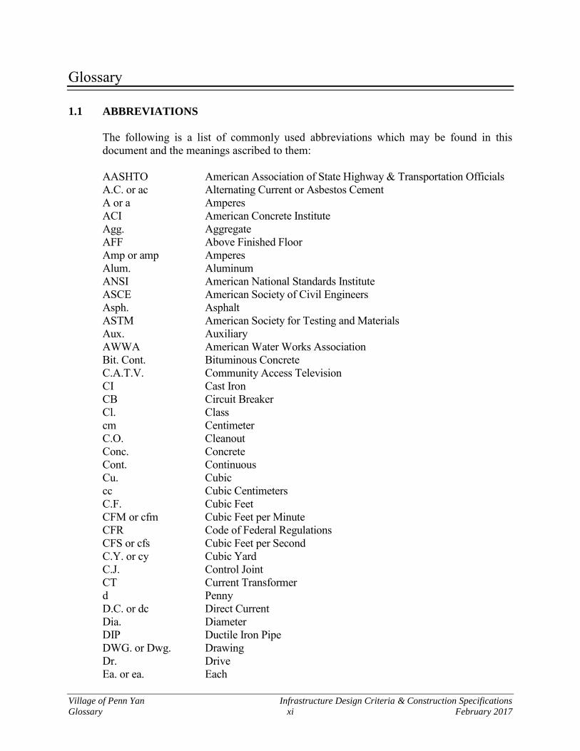
Glossary 1.1 ABBREVIATIONS
The following is a list of commonly used abbreviations which may be found in this document and the meanings ascribed to them:
AASHTO American Association of State Highway & Transportation Officials
A.C. or ac Alternating Current or Asbestos Cement A or a Amperes ACI American Concrete Institute Agg. Aggregate AFF Above Finished Floor Amp or amp Amperes Alum. Aluminum ANSI American National Standards Institute ASCE American Society of Civil Engineers Asph. Asphalt ASTM American Society for Testing and Materials Aux. Auxiliary AWWA American Water Works Association Bit. Cont. Bituminous Concrete C.A.T.V. Community Access Television CI Cast Iron CB Circuit Breaker Cl. Class cm Centimeter C.O. Cleanout Conc. Concrete Cont. Continuous Cu. Cubic cc Cubic Centimeters C.F. Cubic Feet CFM or cfm Cubic Feet per Minute CFR Code of Federal Regulations CFS or cfs Cubic Feet per Second C.Y. or cy Cubic Yard C.J. Control Joint CT Current Transformer d Penny D.C. or dc Direct Current Dia. Diameter DIP Ductile Iron Pipe DWG. or Dwg. Drawing Dr. Drive Ea. or ea. Each
Village of Penn Yan Infrastructure Design Criteria & Construction Specifications
Glossary xii February 2017
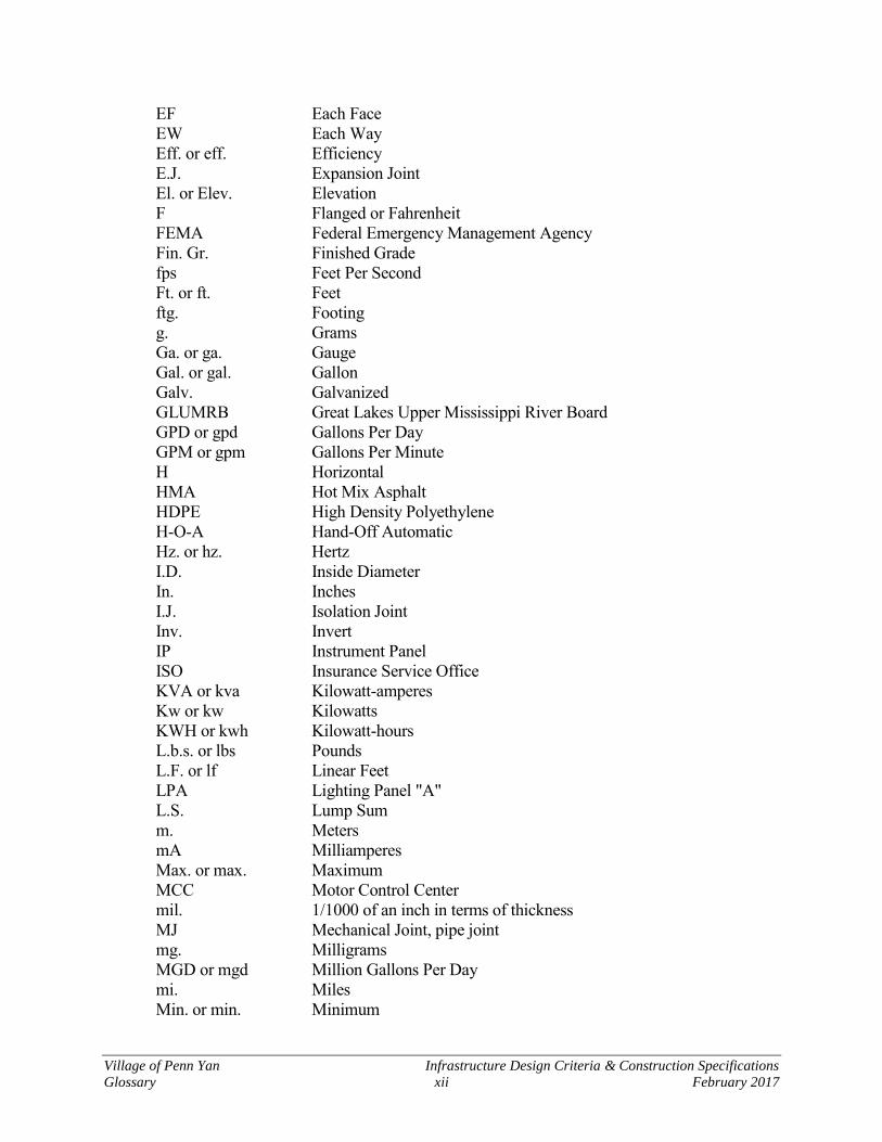
EF Each Face EW Each Way Eff. or eff. Efficiency E.J. Expansion Joint El. or Elev. Elevation F Flanged or Fahrenheit FEMA Federal Emergency Management Agency Fin. Gr. Finished Grade fps Feet Per Second Ft. or ft. Feet ftg. Footing g. Grams Ga. or ga. Gauge Gal. or gal. Gallon Galv. Galvanized GLUMRB Great Lakes Upper Mississippi River Board GPD or gpd Gallons Per Day GPM or gpm Gallons Per Minute H Horizontal HMA Hot Mix Asphalt HDPE High Density Polyethylene H-O-A Hand-Off Automatic Hz. or hz. Hertz I.D. Inside Diameter In. Inches I.J. Isolation Joint Inv. Invert IP Instrument Panel ISO Insurance Service Office KVA or kva Kilowatt-amperes Kw or kw Kilowatts KWH or kwh Kilowatt-hours L.b.s. or lbs Pounds L.F. or lf Linear Feet LPA Lighting Panel "A" L.S. Lump Sum m. Meters mA Milliamperes Max. or max. Maximum MCC Motor Control Center mil. 1/1000 of an inch in terms of thickness MJ Mechanical Joint, pipe joint mg. Milligrams MGD or mgd Million Gallons Per Day mi. Miles Min. or min. Minimum
Village of Penn Yan Infrastructure Design Criteria & Construction Specifications
Glossary xiii February 2017
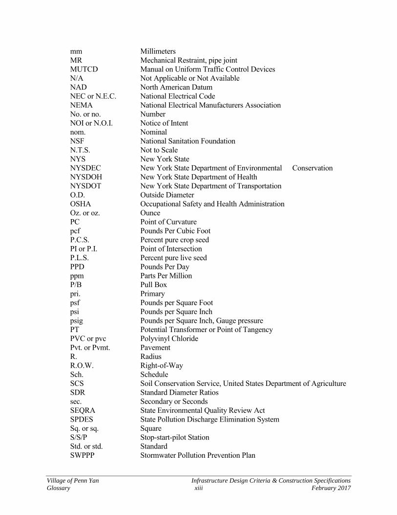
mm Millimeters MR Mechanical Restraint, pipe joint MUTCD Manual on Uniform Traffic Control Devices N/A Not Applicable or Not Available NAD North American Datum NEC or N.E.C. National Electrical Code NEMA National Electrical Manufacturers Association No. or no. Number NOI or N.O.I. Notice of Intent nom. Nominal NSF National Sanitation Foundation N.T.S. Not to Scale NYS New York State NYSDEC New York State Department of Environmental Conservation NYSDOH New York State Department of Health NYSDOT New York State Department of Transportation O.D. Outside Diameter OSHA Occupational Safety and Health Administration Oz. or oz. Ounce PC Point of Curvature pcf Pounds Per Cubic Foot P.C.S. Percent pure crop seed PI or P.I. Point of Intersection P.L.S. Percent pure live seed PPD Pounds Per Day ppm Parts Per Million P/B Pull Box pri. Primary psf Pounds per Square Foot psi Pounds per Square Inch psig Pounds per Square Inch, Gauge pressure PT Potential Transformer or Point of Tangency PVC or pvc Polyvinyl Chloride Pvt. or Pvmt. Pavement R. Radius R.O.W. Right-of-Way Sch. Schedule SCS Soil Conservation Service, United States Department of Agriculture SDR Standard Diameter Ratios sec. Secondary or Seconds SEQRA State Environmental Quality Review Act SPDES State Pollution Discharge Elimination System Sq. or sq. Square S/S/P Stop-start-pilot Station Std. or std. Standard SWPPP Stormwater Pollution Prevention Plan
Village of Penn Yan Infrastructure Design Criteria & Construction Specifications
Glossary xiv February 2017
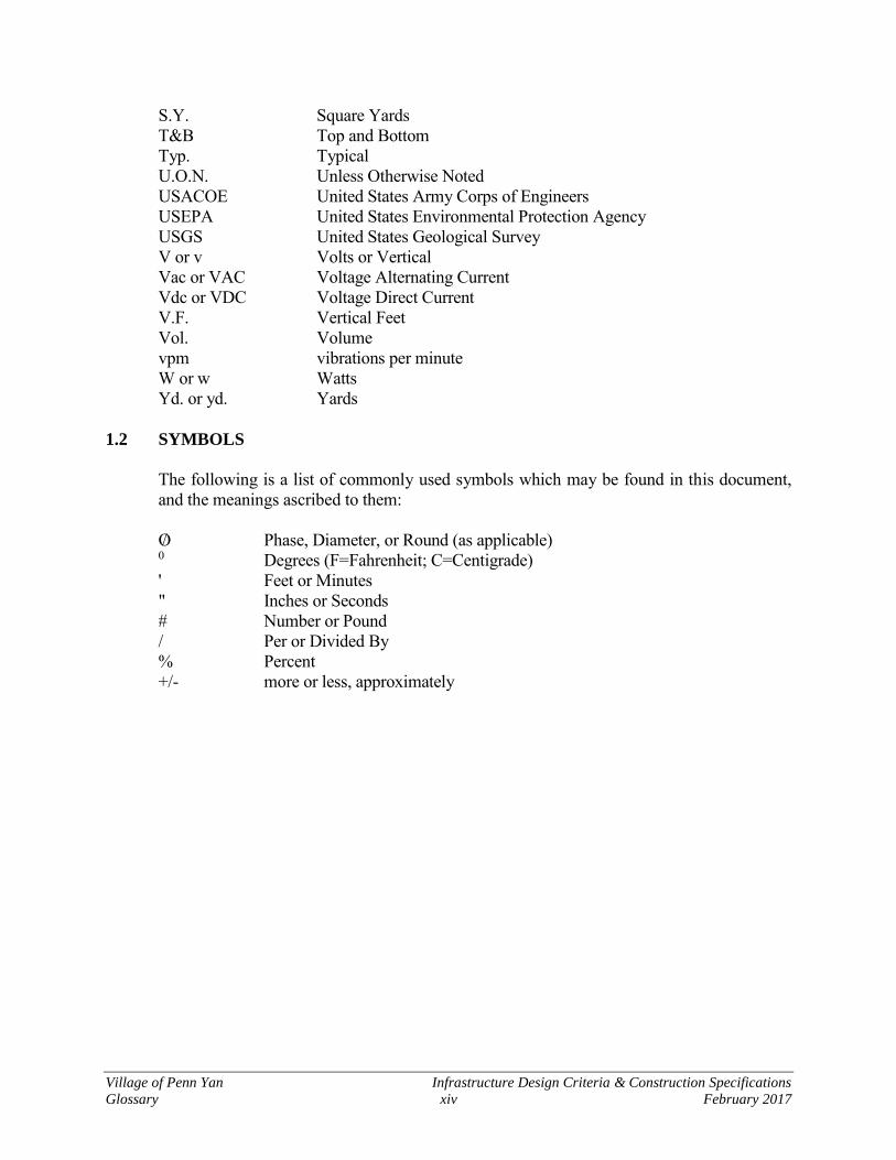
S.Y. Square Yards T&B Top and Bottom Typ. Typical U.O.N. Unless Otherwise Noted USACOE United States Army Corps of Engineers USEPA United States Environmental Protection Agency USGS United States Geological Survey V or v Volts or Vertical Vac or VAC Voltage Alternating Current Vdc or VDC Voltage Direct Current V.F. Vertical Feet Vol. Volume vpm vibrations per minute W or w Watts Yd. or yd. Yards 1.2 SYMBOLS
The following is a list of commonly used symbols which may be found in this document,
and the meanings ascribed to them:
AO/E A Phase, Diameter, or Round (as applicable) P
0P Degrees (F=Fahrenheit; C=Centigrade)
' Feet or Minutes " Inches or Seconds # Number or Pound / Per or Divided By % Percent +/- more or less, approximately

Village of Penn Yan Infrastructure Design Criteria & Construction Specifications
Glossary xv February 2017
Introduction This document serves as a standard guide for, and a control over, the development of property with-in the Village of Penn Yan. The intent is to assure proper design and construction of facilities that will be turned over to the Vil-lage of Penn Yan for perpetual maintenance. Further, it is to assure proper design and construction of facilities, which will affect the health and general welfare of the community, minimize long term operating costs, and prevent depreciation of property values. Thirdly, it is to assure that develop-ment is compatible with the long-range development plan of the Village of Penn Yan. It is not the intent of the booklet to conflict with land subdivision regulations, zoning policies, Com-prehensive Master Plan, or general overall supervision of development by the Village Board, Planning Board, or other authorized agencies. Rather, it is intended to supplement such policies by providing the technical details necessary to carry out general policy in a successful manner. This document does not concern itself with control over building design or construction. These mat-ters are covered elsewhere by Village policy and ordinance. This document is divided into four general sections. The first section is “General Regulations”, which deals with general procedures to be followed. The intent is to provide a guide, which will as-sure expeditious review of subdivision plans as well as the consideration of completed works, which are to be turned over to the Village for dedication. The second portion of the booklet is entitled “Design" and provides a guide for Developers, engi-neers, and others involved in the preparation of plans for single units, subdivisions, and other developments. The third portion of the booklet is entitled "Construction" and provides the construction specifica-tions. Owners, Developers, and engineers bear the responsibility of requiring their contractors to familiarize themselves with these specifications and to carry them out during construction. The last section of this booklet consists of “Standard Details” and Appendices. These documents are cross-referenced to basic material in the Design or Construction Sections and usually consist of amendments or modifications to information included therein.

THIS PAGE INTENTIONALLY BLANK

General

THIS PAGE INTENTIONALLY BLANK
Village of Penn Yan Infrastructure Design Criteria & Construction Specifications
General 1 February 2017
Section 1 General Requirements
1.1 Sequence of Procedures - General Developers are required to retain competent engineering and legal counsel to deal with technical matters and provide the necessary detailed information requested. Whenever any subdivision of land (major or minor) is proposed, before any building permit for the erection of a permanent build-ing in such proposed subdivision is granted, and before any subdivision plat may be filed in the office of the Yates County Clerk, the Developer or his authorized agent shall apply for and secure approval of such proposed subdivision. The Developer should contact the Village Planning Board Secretary for an informal discussion that will provide information and guidance related to site plan review, subdivision requirements, appli-cation for hearings, letters of credit and related application/filing fees. The Developer should also consider contacting the Code Enforcement Officer and the Office of Public Works depending on the scope of their project. Informal discussions with these departments will provide valuable guidance related to building permit requirements and available public infrastructure. The Developer's shall file applications for subdivision of land on forms provided by the Village Planning Board Secretary, pay any applicable fees and submit information required for each phase of the review process within the time specified in the subdivision regulation section of the Village Code. No construction of utilities, as defined herein, shall be started without notifying the Department of Public Works. No building permit or right of way permit shall be issued until and unless a letter of credit or certi-fied check, as required by the Village Planning Board, of an amount, and in a form, satisfactory to the Village Attorney has been established, and until all easements, required by the Office of Public Works, have been approved by the Village Attorney, executed by the Village Board and filed in the office of the Yates County Clerk. A sample of a letter of credit is illustrated in Appendix A. The Director of Public Works may request a withdrawal of funds from a letter of credit upon certifi-cation to the Village Board that there is reasonable cause to utilize such funds. After appropriate resolution by the Village Board, removal and use of these funds can be used for the appropriate pur-pose. The letter of credit amount shall include funds necessary for the costs incurred by the Village for inspection, Village Engineer's advisory services during construction, and surveys and testing neces-sary to assure completeness and satisfactory quality of the work. The Village would like to emphasize that they are interested in promoting successful and appropriate land development in the Village.

Village of Penn Yan Infrastructure Design Criteria & Construction Specifications
General 0 February 2017
THIS PAGE INTENTIONALLY BLANK

Village of Penn Yan Infrastructure Design Criteria & Construction Specifications
General 1 February 2017
Section 2 Sequence of Procedures
2.1 Pre-Application Developers shall contact the Village Planning Board Secretary for information and direction relat-ing to site plan review, subdivision application, application for hearings, and related fees. Guidance for coordinating and presenting projects to the Village Planning Board and related pro-cedural matters can be preliminarily discussed. Where utilities are to be connected into the facilities of other agencies, such as gas, cable and telephone, the Developer and his engineer shall be responsible for contacting such agencies di-rectly to determine such regulations as may be in effect and to determine the capacity of these facilities to handle the loadings to be imposed upon them by the new development. 2.2 Minor versus a Major Subdivision of Land
1. Minor Subdivisions:
Any subdivision of land creating not more than four (4) lots within an eighteen (18) month period is considered a minor subdivision.
The Village Planning Board may waive, at its discretion, any part of these proce-dures for the application of a minor subdivision of land. However, the Village Planning Board requires as a minimum the submission of a minor subdivision plan that indicates the Developer’s plan and ultimate disposition of the land.
2. Major Subdivisions – The application and review process for major subdivisions includes the following phases: Sketch Plan Review, Preliminary Plan Review and Final Plan Review.
2.3 Sketch Plan Review All plans to develop property in the Village of Penn Yan that involve a subdivision of land shall be presented to the Village Planning Board. Developer should be prepared to present a plan and related data to show the intended development of the property and how it will relate to adjoining property. The Developer should be prepared to answer questions relating to utilities, topography, and drainage. The sketch/concept plan submission should include the following:
1. Written statement outlining the proposed project.
2. Location Plan showing the general location of the site with respect to existing and proposed streets, rights-of-way, easements, buildings, and other facilities and nat-ural features.
Village of Penn Yan Infrastructure Design Criteria & Construction Specifications
General 2 February 2017
3. Specific identification of all properties, subdivisions, and streets within five hun-dred (500) feet of the parcel.
4. General identification of all existing and any proposed new, upgraded, or extend-
ed utilities, including but without limitation, electricity, telephone, natural gas, petroleum, other liquid pipelines, cable television, water, sewage, storm water disposal, and drainage facilities in the area.
5. Identification of internal streets and traffic circulation patterns, if any, of the pro-
posed development.
6. The location of all existing and proposed structures on the site and the designated uses for each.
7. Identification of existing zoning classification(s) of the property, of all adjacent
properties, and any restriction on land use of the site.
8. Identification of the existing natural features on the site.
9. A copy of the appropriate USGS map (s). No formal action shall be taken on the plan or the application at the time of the Sketch Plan Re-view. The Village Planning Board may suggest changes, which in the opinion of the Village Planning Board, would improve the site design concept. 2.4 Preliminary Plan Review All applications for a Preliminary Plan approval shall be made in writing on the appropriate form. If the appropriate environmental assessment form has not been previously submitted, it should be included in the preliminary plan submittal. Once the Village Planning Board has determined that the preliminary site plan application is complete, the Village Planning Board shall submit a copy of the site plan to the County Planning Agency for their review, as required by General Municipal Law, Section 239 l, m and n. and/or to others as directed by the Village Planning Board. Refer to Section 3, General Design Re-quirements, for detailed requirements. All review comments on the Developer’s Preliminary Plan application from the Village Planning Board and County Planning Board relative to its completeness will be shared with the Developer within two weeks of receiving it. The Developer should then submit for their Final Plan review within two weeks of the next regularly scheduled Village Planning Board meeting.
Village of Penn Yan Infrastructure Design Criteria & Construction Specifications
General 3 February 2017
2.5 Final Plan Review After receiving preliminary recommendation, with or without modifications, from the Village Planning Board on a Preliminary Plan, the applicant may prepare a final detailed site plan and sub-mit it to the Village Planning Board for approval. In addition to final detailed site plans, the following additional information shall accompany an application for final site plan approval:
1. A record of application for all necessary permits from village, county, and state departments or agencies;
2. Submission of evidence that the State Environmental Quality Review Act (SEQRA) has been complied with;
3. An estimated project construction schedule;
4. Submission of all proposed easement agreements;
5. Submission of evidence of firm financial commitments for project construction and permanent financing for completion of the project;
6. Submission of evidence that all water, sewage, and storm water disposal and drainage facilities are in compliance with all applicable federal, New York State, Yates County, and Village of Penn Yan laws, ordinances, rules, regulations, or-ders, and permits;
7. A Stormwater Pollution Prevention Plan (SWPPP) meeting the requirements of NYSDEC when the project will result in the disturbance of more than one acre; and
8. Any other information or data deemed necessary by the Village Planning Board site plan checklist.
Upon approval of the final site plan and payment by the applicant of all fees and reimbursable costs due to the Village, the Village Planning Board shall endorse its approval on a copy of the final site plan. Village Planning Board approval of a final site plan shall expire after one (1) year from the date of such decision, unless a substantial work has been completed on the final site plan and site development and/or construction has begun as determined by the Code Enforce-ment Officer. The Village Planning Board may approve, approve with conditions or modifications, or not rec-ommend the final plan. The Village Planning Board may also reserve decision pending receipt of additional information or data.
Village of Penn Yan Infrastructure Design Criteria & Construction Specifications
General 4 February 2017
2.6 Special Improvement Districts In those projects that require the establishment or extension of a sanitary sewer, water, or other special districts, the following items must be completed by the Developer and submitted to the Director of Public Works prior to obtaining the signature of the Village Planning Board.
A properly written metes and bounds description of each district;
A listing of all parcels to be included; and
A petition requesting that the Village establishes the specific district or extension. 2.7 Easements It shall be the responsibility of the Developer to furnish, in the required format, all necessary easement documents. Easements may be obtained for such items as storm and sanitary sewers, water mains, electric infrastructure, sidewalks, dedicated streets, drainage, conservation areas, pedestrian access (trails), and cross access rights. The Developer shall provide a properly written metes and bounds description of each easement to the Office of Public Works. A reduced scale drawing showing the location of all easements with relationship to property lines shall accompany these descriptions. After a preliminary review of these documents by the Director of Public Works, the documents shall be transmitted to the Village Attorney for his final review. In addition, the Developer shall provide the Village a check in an amount to be determined by the Village Attorney to cover the cost of recording these documents in the Yates County Clerk's Of-fice. These documents shall be recorded in the Yates County Clerk's Office by the Village Attorney. Filing fees for the recording of easements and/or other documents shall be paid by the Developer. The aforesaid shall be on file with the Village prior to obtaining the signature of the Village Planning Board. 2.8 Acceptance of Land to be Dedicated The Developer shall be responsible for all properties to be dedicated to the Village of Penn Yan until such time as the Village Board formally accepts said lands by Village Board resolution. Prior to the acceptance of any properties to be dedicated to the Village of Penn Yan, including but not limited to: roadways, sidewalks, storm sewers, sanitary sewers, water mains, detention ponds, recreational facilities, easements and special districts, all improvements and properties shall be completed to the satisfaction of the Village.

Village of Penn Yan Infrastructure Design Criteria & Construction Specifications
General 5 February 2017
The Developer shall be responsible for all current taxes due on properties to be dedicated to the Vil-lage up to the date of that the Village accepts said dedicated lands. After lands to be dedicated have been prepared in a manner acceptable to the Village of Penn Yan, the Developer shall request, in writing to the Village Board, acceptance of said lands. Upon acceptance by the Village, the funds retained in the Developer's Irrevocable Letter of Credit/cash deposit shall be returned. The Developer shall pay the appropriate filing fees for all documents to be recorded by the Vil-lage Attorney. 2.9 Irrevocable Letter of Credit Financial responsibility of the Developer shall be in the form of an Irrevocable Letter of Credit from a recognized banking facility within the State of New York or an escrow deposit with the Village of Penn Yan in the form of cash, certified check, or cashier's check. Upon receiving ap-proval of a particular subdivision section and/or site plan, the Developer's licensed professional engineer shall submit an "Estimate of Improvements". The Developer's engineer's estimate shall be reviewed and approved by the Village Planning Board in writing. An executed Developer's Agreement, in the Village's standard format, and the Irrevocable Letter of Credit is required prior to the start of any work. An Irrevocable Letter of Credit shall be itemized in detail and shall con-sist of, but not limited to, the following minimum items:
A. Water Distribution System
1. Water piping 2. Hydrant assemblies 3. Valves 4. Water services 5. Restoration of surfaces 6. Testing 7. Road bore 8. Lawn restoration 9. Driveway restoration 10. Roadway restoration
B. Sanitary Sewer System
1. Sewer piping (including wye branches) 2. Sanitary manholes 3. Laterals 4. Pump stations (as applicable)

Village of Penn Yan Infrastructure Design Criteria & Construction Specifications
General 6 February 2017
C. Storm Water Collection System
1. Storm sewer piping 2. Storm manholes 3. Catch basins 4. Yard inlets 5. End sections 6. Driveway culverts 7. Road culverts 8. Flushing of storm sewer
D. Roadways
1. Road excavation and boxout 2. Road base (including weep wedge and underdrain pipe) 3. Binder pavement 4. Top pavement 5. Concrete gutters/curbing 6. Sidewalks 7. Seeding within R.O.W.
E. Grading and Erosion Control
1. Sediment basins (installation and maintenance) 2. Silt fencing (installation and maintenance) 3. Drainage swales 4. Detention/retention ponds and appurtenances 5. Rock excavation/blasting 6. Re-vegetation of primary swales 7. Lot grading 8. Fill material 9. Dust control
F. Miscellaneous
1. Street lights 2. Street signs 3. Plantings
G. Five percent (5%) Village inspection fee on total of items A to F
The detailed estimate shall be summarized as follows: Construction Costs Sections A – F Subtotal 10% Contingency Total Estimated Construction Cost Cost to provide a set of As-built Record Plans
Village of Penn Yan Infrastructure Design Criteria & Construction Specifications
General 7 February 2017
Owner’s Guarantee (5% of total construction cost) Inspection for Dedicated Facilities (5% of total construction cost) TOTAL LETTER OF CREDIT AMOUNT The developer’s engineer’s “Estimate of Improvements” shall be submitted to the Village Plan-ning Board together with a copy of the subdivision and/or site plan for approval. The Irrevocable Letter of Credit document shall be in the Village's approved format. Attached to the Irrevocable Letter of Credit and made a part thereof shall be the Village's Agreement in the approved format (see "Exhibit A"). Such fees normally charged by the Village such as, building permit fees, and right of way permit fees are not covered under the Irrevocable Letter of Credit but must be paid to the Village prior to the issuance of a building permit. The letter of credit shall be written so as to comply with the terms and conditions specified by the Village, as set forth in a specimen copy of a letter of credit that has been approved by the Village Attorney, which is shown in Appendix 1. The Village shall release from the letter of credit, upon satisfactory and approved installation of the sanitary and storm sewers, 60% of the money allocated for these items in the letter of credit. After approved testing, cleaning, and sealing of manholes, an additional 40% of the money set aside shall be released. Sewers may not be tested until the completion of rough road boxing, but shall be done prior to the placement of road materials. Any pipe repair work must be done in an approved manner by using acceptable patented repair sleeves or by removing and replacing damaged pipe. Repairs to sanitary sewers by using concrete patches or other inferior workmanship will not be permitted. The contingency item (10%) is intended to cover unforeseen costs from any extras or changes in quantities or types of materials used on the project. The contingency amount can be used at the Vil-lage's discretion to reimburse the inspection account or cover the cost of overruns that occur on the project. The Owner's guarantee (5%) assures the Village of funds to cover the legal and engineering costs or other costs incurred from the transfer of the contract to another contractor for completion. This combined amount (15%) also constitutes a control figure which guarantees that certain items are completed, which include: as-built maps delivered, warranty bond established, final inspection completed and final acceptance by the Village of public improvements which have been made. The letter of credit is to be renewed yearly. That is, renewal is required one year from the date the letter is established, and each year thereafter that the project is active. Prior to each renewal date, the Village Engineer shall review the costs requested in the letter. An increase in the letter of credit dol-lar amount may be required before renewal is permitted, to reflect current construction costs. The Developer must take this into account at each yearly review period. On each construction statement seeking release of funds under the letter of credit, an amount equal to 10% of the work in place shall be retained to cover the cost of cleanup, manhole frame adjust-

Village of Penn Yan Infrastructure Design Criteria & Construction Specifications
General 8 February 2017
ments, finish grading, lateral staking, etc. In general, the 10% retainage shall be taken on sections: (A) water facilities, (B) sanitary facilities, (C) storm drainage and facilities, (D) grading, paving, and sidewalks, (E) erosion control (erosion and dust control, and siltation facilities), (F) miscellaneous (such items as landscaping). In general, no retainage is necessary for such miscellaneous items as engineering, inspection, mass grading, contingencies, and as-built maps once these items have been completed. 2.10 Preparation of Record Plans The Developer shall submit record plans prior to obtaining final approval of completed works. 2.11 Approval of Completed Works and Maintenance Bond Developer is responsible for obtaining approval of completed works by appropriate Village officials and other agencies. Upon completion of the required work under the letter of credit, a maintenance bond shall be estab-lished. All maintenance bond amounts shall be for 10% of the original performance bond, but no maintenance bond shall be for an amount less than $5,000 (face value). If separate bonds are sub-mitted, each will be a minimum of $5,000.00. If the entire project is not completed in a timely manner, the Village has the right to ask for subsequent extensions of the initial maintenance bonds. Inasmuch as weather conditions dictate practicality of performance as well as accessibility for ap-propriate inspection of the improvements, all maintenance bonds shall commence no earlier than June 1 or later than October 1 and expire two (2) years thereafter. Maintenance bonds need not be written to include all dedicated facilities and improvements in one bond. But no more than three (3) maintenance bonds for one subdivision section will be acceptable. If the Developer chooses, maintenance bonds may be established at the completion of the facilities or improvements listed below:
A. Water mains, hydrants, valves, services, etc. B. Sanitary and storm sewers including pump stations, manholes, laterals, etc. C. Roadway construction, including road foundation items, asphalt, curbing or gutters, and
catch basins. D. Drainage facilities such as detention ponds, major creek and ditch work, erosion control, etc.
2.12 Release of Warranty It shall be the Developer's responsibility to notify the Village forty-five (45) days prior to the expira-tion of the warranty period. The Village will make a final inspection and establish a "punch list" of work to be corrected as part of the warranty. Developer shall make necessary repairs prior to com-pletion of warranty period or warranty will be extended.

Village of Penn Yan Infrastructure Design Criteria & Construction Specifications
General 9 February 2017
2.13 Preconstruction Meeting Each development is required to schedule a preconstruction meeting prior to starting any work on the project, unless otherwise determined by the Village Board. The meeting shall be sched-uled through the Office of Public Works. The Developer, or his engineer, is responsible for contacting all applicable outside utility agencies once a meeting date has been determined. The Developer, contractor, subcontractors, and design engineer shall be in attendance at the precon-struction meeting. No work on the project site can begin until after the meeting. The Developer shall provide, at a minimum, the Village Code Enforcement Office with the fol-lowing prior to scheduling the preconstruction meeting:
Five (5) sets of project plans with all approval signatures Irrevocable Letter of Credit and executed Agreement Copies of all required insurance certificates; comprehensive and liability (mini-
mum one (1) million and three (3) million respectively) All required easements and descriptions Copies of all permits from regulatory agencies (NYSDOT, NYSDEC, NYSDOH,
USACOE), and the Village of Penn Yan Copy of the NOI required by the NYSDEC SPDES Permit
This meeting will cover specific details of the project, including, but not limited to the timetables for the development, special conditions, permit requirements, Village Policy, release of funds, erosion control measures, and all other topics of interest to this development. Any questions or problems that may arise during construction should be referred directly to the Code Enforcement Officer. 2.14 Areas of Responsibility The following describes the general areas of responsibility of the various village, county, and state departments that participate in the review and approval of a project in the Village of Penn Yan. This summary is provided to give the Developer an awareness of the parties involved in this process.
A. Clerk Treasurer and Village Board
Clerk/Treasurer is fiscal officer for release of Letter of Credit funds Review and consider dedication roads and other public facilities Review and consider special district requests Review and consider special permits
B. Planning Board
Review all development sites
Village of Penn Yan Infrastructure Design Criteria & Construction Specifications
General 10 February 2017
Conduct public informational meetings Conduct public hearings on subdivisions and site plans Approve or deny applications and determine conditions of approval Grant Special Use Permits for new development Planning Board Chair signs all approved subdivision and site plans.
C. Director of Public Works, Police Chief, Fire Chief and Engineer
When requested by the Planning Board, the Department of Public Works, Chief of Police, Fire Chief and if necessary the Village Engineer shall: Review road layout, site grading, and storm drainage Review all utilities and all matters relative to design criteria and construction
specifications Recommend special conditions and modifications Review and approve the Developer’s engineer’s estimate of costs for improve-
ments Review and approve Developer’s request for release of funds from the Letter of
Credit Periodic inspection of construction when requested by the Village Make warranty inspection
D. Attorney
Review all necessary legal documents of the formation of necessary improvement districts
Review all necessary legal documents for dedication, easements, Letter of Credit and Surety Bond
Record all required legal documents for dedication and easements
E. Village Department Heads for Streets, Water, Sewer & Electric
Inspect the construction of all dedicated street construction Inspect dedicated streets and drainage facilities prior to end of warranty period
F. New York State Department of Health
Review and approve plans for public water supply improvements
G. New York State Department of Environmental Conservation
Review and approve plans for dedicated sanitary sewer improvements Review NOI for compliance with requirements of the SPDES General Permit for
Stormwater Discharges from Construction Activity Issue permits required by NYS Environmental Conservation Law

Design

THIS PAGE INTENTIONALLY BLANK
Village of Penn Yan Infrastructure Design Criteria & Construction Specifications
Design 13 February 2017
Section 3 General Design Requirements
3.1 General The development of property shall conform to Subdivision of Land Regulations and zoning restric-tions established by the Village. It shall also conform with all regulations established herein as well as to appropriate laws, rules, and regulations established by all governing bodies having or claiming jurisdiction over various phases of the development. Where a conflict arises between these regulations and those of other agencies, the Developer shall make it known to the conflicting agencies the area of disagreement and endeavor to have such agen-cies resolve their differences before proceeding with development. Though these standards have principally been developed to apply to subdivisions, they shall apply to other developments as well to the extent that the standards are applicable. 3.2 Basis of Design, General The term "utilities" as used herein shall be defined as roads, drains, sewers, water mains, and ap-purtenances thereto which will, upon acceptance by the Village, be turned over to the Village or other public agency for maintenance and operation. Utilities shall be designed to conform to the topography of the property and existing utilities on adjacent streets or property. Developers shall satisfy themselves by preliminary investigation, and consultation with appropriate Village officials, as to the adequacy of adjoining facilities up-on which their property must rely for service, most particularly water mains, sewers, drains and culverts. Developers bear the responsibility of providing sound engineering design of all utilities, subject to the approval of the Village. The design shall be prepared by a professional engineer licensed to practice in the State of New York, who shall have had experience in the design of such utili-ties. The design shall conform to the requirements set forth herein. A brief report describing the basis of design for the storm drainage, sanitary sewer and water lines shall be submitted with the preliminary and final plan submittal. 3.3 Submission of Plans and Pertinent Data The Developer shall submit a sketch plan/concept plan, preliminary and final plans as outlined in the Sequence of Procedures in the front of this book, and as required by such other Village policy or local, State, or Federal laws and regulations as may be in force and as are applicable.
A. Engineer’s Report
The applicant shall submit a report addressing the following minimum items for consid-eration by the Village of Penn Yan:
Village of Penn Yan Infrastructure Design Criteria & Construction Specifications
Design 14 February 2017
Description and design calculations for the storm water management system and water quality improvements;
Description and design calculations for the water supply and fire protection sys-tem;
Description of erosion control plans; Description and design calculations for the sanitary sewer disposal system, in-
cluding capacity of downstream facilities; Description and design calculations for traffic generation from the site and the
level of service for adjacent intersections; Test pit results for rock and water table determination; Engineer's estimate for construction costs.
B. Required Drawings
In preparing the detailed subdivision (development) plans the Developer shall subdivide the project into three (3) major "sets" of plans as follows:
Subdivision Plat Record Plan Subdivision Grading & Drainage Plan Subdivision Utility & Street Plan
Submission requirements for other types of developments shall be in accordance with ap-plicable ordinances.
Specifically, the drawings shall include, but not be limited to, the following:
1. Subdivision Plat Record Plan
All maps must be prepared on such medium and be of such size as will be accept-ed by the County Clerk for filing, and shall be drawn at a minimum scale of 50' to 1" unless otherwise approved. Where more than one sheet is required to show the entire development, a key map showing all sections shall be provided. The fol-lowing information shall be clearly shown:
a. Title of the sheet, including name and address of the design engineer, Own-
er and Developer and all required signatures. (Where Developer or owner is a corporation, a statement of corporate ownership and officers shall be submitted to the Planning Board, at the preliminary stage).
b. North point, graphic scale, and date.
c. The boundaries of the subdivision and information to show the location of the subdivision in relation to surrounding property and streets, including names of owners of adjacent land or names of adjacent subdivision. In whatever manner that is practical, the subdivision boundary shall be refer-enced from two directions. The map shall contain a notation of the location and elevation of a benchmark referenced to USGS datum. All plans should

Village of Penn Yan Infrastructure Design Criteria & Construction Specifications
Design 15 February 2017
be tied into the NYS Plane Coordinate System using the NAD 83 datum. In the event that such monuments have been obliterated, the subdivision boundary shall be referenced to the nearest highway intersections or at least two previously established monuments of subdivisions of public lands. Any combination of types of reference ties may be accepted which would fulfill the requirement of exact measurements from the subdivision boundary to reference points previously established.
d. The location and widths of existing and proposed streets and events within the subdivision and the lines of existing or approved streets on adjoining properties. (Street name must be approved by the Village Board.)
e. The names of existing and proposed streets.
f. All maps shall show the location of existing buildings and septic systems within the limits of the map, with front, rear, and side setbacks from any lot line with dimensions thereof and all existing buildings outside the limits of the map, within one hundred feet (100’) of any proposed street or any pro-posed lot line. All corner lots must show building location. Also setbacks for corner lots and exterior lots must be consistent with the current zoning ordinance.
g. The lines and dimensions of proposed lots, which shall be numbered and shall have their area in square feet indicated.
h. The lines and purposes of existing and proposed easements immediately ad-joining and within the subdivision.
i. The lines and dimensions of all property which is offered, or to be offered, for dedication for public use, with the purpose indicated thereon, and of all property that is proposed to be reserved by deed covenant for the common use of the property owners of the subdivision.
j. The location of monuments to be placed within the subdivision.
k. The locations of any municipal and zoning boundary lines within the subdi-vision, including fire districts, school districts, and special use districts
l. Statements as to:
The zoning of the property within the subdivision. Compliance of the proposed lots with zoning requirements. If any lots do not comply but are covered by zoning variances, the statement should in-clude reference to such variance.
m. Certification by a licensed land surveyor as evidence of professional re-
sponsibility for the preparation of the plat and a place for the liber and page

Village of Penn Yan Infrastructure Design Criteria & Construction Specifications
Design 16 February 2017
where filed. In addition, a licensed professional engineer shall place his seal and signature on the plat map as evidence of professional responsibility for any engineering work also shown thereon.
n. Plans for each phase of the subdivision shall contain an overall plan show-ing layout of all proposed and existing lots associated with the project.
2. Subdivision Grading and Drainage Plan
This plan shall be on a separate sheet of the same size and scale as the plat and provide the following information:
a. The plan shall contain date, north arrow, and graphic seal.
b. Contours of existing grade at intervals of not more than 2'. Intervals of l' may be required depending on the character of the topography and lot sizes. A separate grading map will be required where the terrain is such to make it necessary.
c. Approximate location of all adjacent and proposed buildings.
d. Number of each lot and area in square feet.
e. The location and grade of all driveways and roadways adjacent to the prop-erty under construction.
f. Location of all existing swales, creeks, ponds, drainage outlets, and other drainage structures with invert elevations.
g. Final grades and/or contours at intervals of not more than 2', lesser intervals may be required depending on topography, including the location of all swales, creeks, ponds, drainage outlets, and other drainage structures with invert elevations.
h. Location and means of controlling erosion within the project limits.
i. Slope stabilization details.
j. Flood hazard prevention, when applicable.
k. Storm water detention basins and ground recharge facilities.
l. Seal, signature, and address of the New York State licensed professional engineer responsible for the engineering work.
3. Subdivision Utility and Street Plans
Village of Penn Yan Infrastructure Design Criteria & Construction Specifications
Design 17 February 2017
This plan shall be on a separate sheet(s) of the same size and scale as the plat and provide the following details:
a. Seal and signature of the NYS licensed professional engineer responsible
for the engineering work.
b. The plans shall show the plan of any water or sewer utilities (storm water and/or sanitary).
c. The map shall show the location, material, class, inverts, and size of exist-ing sewers (storm water and/or sanitary) and appurtenances on the subject or adjoining property or into which any connection is proposed, including all appurtenances. The size, material, and location of catch basins and yard inlets should be provided.
d. The map shall contain date, north arrow, scale, tie to nearest generally known point, point of tangency, point of curvature, length of tangent, length of radius of curve and all angles or bearings for the proposed roadway and right-of-way.
e. The map shall show plans for highways, including concrete gutters, swales, curbing, and storm water sewer collection systems.
f. The map shall contain plans and profiles for highways, including storm wa-ter sewers, sanitary sewers and water supply system piping in accordance with accepted standards.
g. The map shall indicate the type, material, class, and size of all existing and proposed water mains and appurtenances.
h. The map shall show the hydrant flow data for existing water mains and the location of the nearest hydrant.
i. All plans shall be tied into the State Plane Coordinate System using the NAD 83 datum and New York State West zone coordinate system.
Village of Penn Yan Infrastructure Design Criteria & Construction Specifications
Design 18 February 2017
THIS PAGE INTENTIONALLY BLANK
Village of Penn Yan Infrastructure Design Criteria & Construction Specifications
Design 19 February 2017
Section 4 Road, Street, and Pavement
4.1 General Where a conflict arises between these regulations and those of other agencies, the Developer shall make known to the conflicting agencies the area of disagreement and endeavor to have such agen-cies resolve their differences before proceeding with development. Though these standards have principally been developed to apply to subdivisions, they shall apply to other developments as well to the extent that the standards are applicable. 4.2 Basis of Design, General The term "facilities" as used herein shall be defined as road or street improvement, gutters, side-walk, and related improvements, which will, upon acceptance by the Village, be turned over to the Village for maintenance and operation. Facilities shall be designed to conform to the topography of the property and existing utilities on adjacent streets or property. Developers shall satisfy themselves by preliminary investigation, and consultation with appropriate Village officials, as to the adequacy of adjoining facilities upon which their property must rely for service. Developers bear the responsibility of providing sound engineering design of all facilities, subject to the approval of the Village. The design shall be prepared by a professional engineer licensed to practice in the State of New York, who shall have had experience in the design of such facilities. The design shall conform to the requirements set forth herein. A brief description describing the ba-sis of design shall be included in the project engineering report and submitted with the preliminary and final plan submittal. 4.3 Proper Design New facilities to be owned and maintained by the Village shall be designed by a professional li-censed engineer to practice in New York State, in accordance with the requirements of this Design Criteria and Construction Specifications. For requirements not specifically stated in the document, the AASHTO publication A Policy on Geometric Design of Highways and Streets – 2011 or most recent revision shall apply. Plans and specifications shall be submitted to, and written approval shall be obtained from the Village and the NYS Department of Transportation, before initiating any con-struction. The design shall anticipate and allow for flows from all possible future extensions or developments within the immediate drainage area. 4.4 Street Arrangement Street systems shall be designed with due regard to the needs for: convenient traffic access and cir-culation; traffic control and safety; pedestrian and bicycle circulation access for firefighting and emergency vehicles, snow removal, and street maintenance equipment; and storm water drainage
Village of Penn Yan Infrastructure Design Criteria & Construction Specifications
Design 20 February 2017
and sewage disposal. Streets shall be designed to accommodate the prospective traffic, and so ar-ranged as to separate through traffic from neighborhood traffic insofar as it is practicable.
The streets in contiguous subdivisions shall be coordinated so as to compose a convenient system. When a subdivision adjoins undeveloped land, the subdivision streets shall be laid out in a manner, which will provide suitable access and future street connection to the adjoining undeveloped land. Streets for this purpose shall be constructed to the subdivision boundary and temporarily dead-ended. Temporary dead end streets in excess of 200 feet shall be provided with a temporary turna-round. A temporary easement shall be provided to the Village for the turn around and shall remain in effect until such time as the street is extended. A notation to this effect shall be provided on the subdivision plat map. These same requirements shall apply at the discretion of the Village Board in those cases where the adjoining land is another section of the same subdivision, and which is not scheduled for development at the same time.
Streets shall be arranged to conform as closely as possible to the original topography, to minimize grading and disturbance of the existing physical characteristics of the site. The street shall not have steep grades or sharp curves. Building sites shall be constructed at or above the grade of the streets in as many locations as practical and should be a consideration for selecting the roadway align-ment.
The suitability of a soil as a roadway subgrade is an important engineering consideration. The Vil-lage Board reserves the right to require the use of a geotextile filter fabric of a type appropriate for roadway bed containment, underdrain, or other intended use. Geotextiles which are on the current Approved List issued by the New York State Department of Transportation Materials Bureau or approved by the Village Engineer shall be acceptable. Where a development abuts or contains an existing or proposed arterial street or other existing village, county or state highway the Village Board may require marginal access streets, reverse frontage with screen planting contained in a non-access reservation along the rear property line, deep lots with or without rear service alleys, or such other treatment as may be necessary for ad-equate protection of residential properties and to afford separation of through and local traffic.
Where a development borders or contains an existing or proposed railroad right-of-way or con-trolled access highway right-of-way, the Village Board may require a street approximately parallel to and on each side of such right-of-way, at a distance suitable for the appropriate use of the inter-vening land, as for park purposes in residential districts, or for business, commercial or industrial purpose in appropriate districts. Such distances shall also be determined with due regard for the requirements of approach grades and future grade separation. 4.5 Temporary Dead-end Streets
Where a street does not extend to the boundary of the subdivision and its continuation is not needed for access to adjoining property, it shall be separated from such boundary by a distance sufficient to accommodate a lot meeting the requirements of the Zoning Ordinance. Reserve strips of land shall not be left between the end of a proposed street and an adjacent piece of prop-
Village of Penn Yan Infrastructure Design Criteria & Construction Specifications
Design 21 February 2017
erty. However, the Village Board may require the reservation of an easement 30 feet wide for pedestrian traffic or utilities. 4.6 Standards for Street Design
Street design standards are provided for the following classifications of streets:
1. Non-dedicated private drive: defined as a privately owned drive serving a maxi-
mum of four housing units.
2. Parkway road: defined as a street serving a maximum of 12 housing units.
3. Minor street: defined as a street serving a maximum of 150 housing units.
4. Collector street: defined as a street serving over 150 housing units.
Typical sections for each of the street classifications are provided in the standard detail sheets, as well as typical restoration details for excavations in existing streets. All street construction or repair shall be designed in accordance with the standard details and the design criteria in Table 1.
4.7 Street Intersections
1. Intersections involving an arterial street shall be held to a minimum and spaced at least 1,320 feet apart. Intersections involving a collector street shall be a mini-mum of 880 feet apart. Intersections involving two minor streets shall be a minimum of 440 feet apart and shall not be cross (four cornered) intersections in-sofar as possible.
2. Within 50 feet of an intersection, streets shall be approximately at right angles and in no case shall the angle of intersection be less than 75 degrees. Minimum curb, pavement or gutter radii shall depend on the intersecting street types; and shall be as follows:
Collector with arterial: 35 feet Minor with arterial: 35 feet Collector with collector: 35 feet Minor with collector: 30 feet Minor with minor: 30 feet Non-dedicated private drive with minor: 30 feet
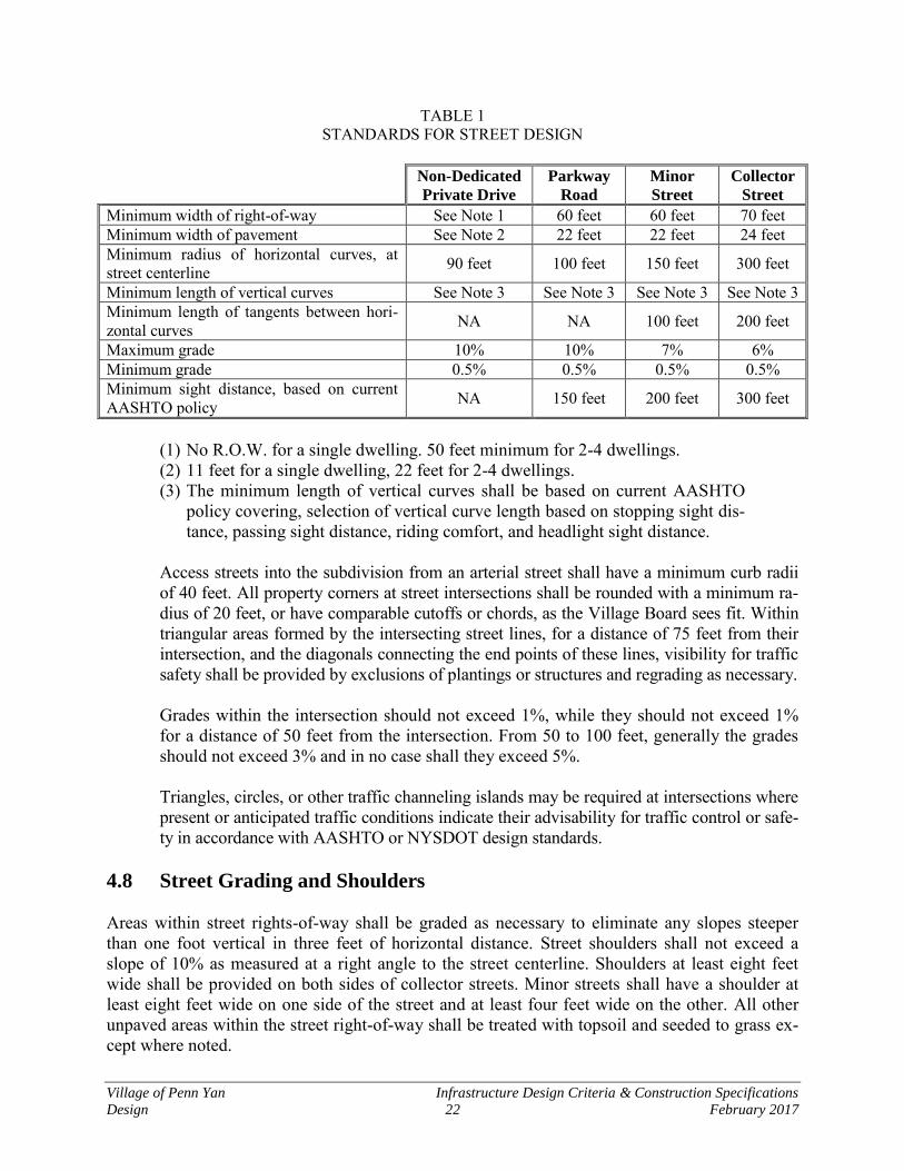
Village of Penn Yan Infrastructure Design Criteria & Construction Specifications
Design 22 February 2017
TABLE 1 STANDARDS FOR STREET DESIGN
Non-Dedicated
Private Drive
Parkway
Road
Minor
Street
Collector
Street
Minimum width of right-of-way See Note 1 60 feet 60 feet 70 feet Minimum width of pavement See Note 2 22 feet 22 feet 24 feet Minimum radius of horizontal curves, at street centerline 90 feet 100 feet 150 feet 300 feet
Minimum length of vertical curves See Note 3 See Note 3 See Note 3 See Note 3 Minimum length of tangents between hori-zontal curves NA NA 100 feet 200 feet
Maximum grade 10% 10% 7% 6% Minimum grade 0.5% 0.5% 0.5% 0.5% Minimum sight distance, based on current AASHTO policy NA 150 feet 200 feet 300 feet
(1) No R.O.W. for a single dwelling. 50 feet minimum for 2-4 dwellings. (2) 11 feet for a single dwelling, 22 feet for 2-4 dwellings. (3) The minimum length of vertical curves shall be based on current AASHTO
policy covering, selection of vertical curve length based on stopping sight dis-tance, passing sight distance, riding comfort, and headlight sight distance.
Access streets into the subdivision from an arterial street shall have a minimum curb radii of 40 feet. All property corners at street intersections shall be rounded with a minimum ra-dius of 20 feet, or have comparable cutoffs or chords, as the Village Board sees fit. Within triangular areas formed by the intersecting street lines, for a distance of 75 feet from their intersection, and the diagonals connecting the end points of these lines, visibility for traffic safety shall be provided by exclusions of plantings or structures and regrading as necessary.
Grades within the intersection should not exceed 1%, while they should not exceed 1% for a distance of 50 feet from the intersection. From 50 to 100 feet, generally the grades should not exceed 3% and in no case shall they exceed 5%.
Triangles, circles, or other traffic channeling islands may be required at intersections where present or anticipated traffic conditions indicate their advisability for traffic control or safe-ty in accordance with AASHTO or NYSDOT design standards.
4.8 Street Grading and Shoulders
Areas within street rights-of-way shall be graded as necessary to eliminate any slopes steeper than one foot vertical in three feet of horizontal distance. Street shoulders shall not exceed a slope of 10% as measured at a right angle to the street centerline. Shoulders at least eight feet wide shall be provided on both sides of collector streets. Minor streets shall have a shoulder at least eight feet wide on one side of the street and at least four feet wide on the other. All other unpaved areas within the street right-of-way shall be treated with topsoil and seeded to grass ex-cept where noted.
Village of Penn Yan Infrastructure Design Criteria & Construction Specifications
Design 23 February 2017
4.9 Sidewalks
Concrete sidewalks shall be provided in locations where they are deemed by the Village/Planning Board to be appropriate and in the interest of public safety or convenience and in accordance with the typical road section detail. Sidewalks shall be required by the Village for safety or convenience. The minimum width of side-walks shall be four (4) feet in width, with an option to be six (6) feet in width where deemed necessary by the Village. 4.10 Trees
The Developer shall take adequate measures to preserve desirable existing trees in suitable loca-tions within the subdivision. In general, the street right-of-way shall be cleared of existing trees in new pavement areas, but occasional existing trees of unusual value may be preserved within the street right-of-way if ap-proved by the Village Board. Existing trees outside of the pavement areas shall be preserved, as they are desired by the Village to maintain part of the character of the Village aesthetics. New street trees shall be provided wherever and whenever possible that do not conflict with utilities, sidewalks and driveways. 4.11 Street Names and Signs
All streets shall be named, and such names shall be subject to the approval of the Village Board. Names shall be sufficiently different in sound and spelling from other street names in the Village and post offices contiguous to the Village to minimize confusion. A street which is a continuation of an existing street shall bear the same name. Relating street names to features of local historical, topographical, or other natural interest is encouraged. Signs shall be in accordance with the Na-tional Manual on Uniform Traffic Control Devices (MUTCD) for streets and highways and 17NYCRR Chapter V (New York State Supplement). 4.12 Monuments
Permanent survey monuments shall be set in the boundary of rights-of-way at intersecting streets, PC and PT of curves, though the P.I. of short curves may be used instead, where such is practical, at the discretion of the Director of Public Works and/or the Village Engineer. Monuments shall be placed on one side of the street only and at only one corner of intersecting streets. Adjacent monu-mented points shall be intervisible. Monument locations shall be shown on the subdivision plat; field notes of ties to monuments or a tie sheet shall be submitted to the Village Engineer after installation of monuments.
Village of Penn Yan Infrastructure Design Criteria & Construction Specifications
Design 24 February 2017
Monuments shall be of stone or concrete and not less than 4 inches in diameter or square, and not less than 42 inches long or from the top of underlying rock. Concrete monuments shall be rein-forced with steel rods, and a plug, brass plate, or pin shall serve as the point of reference. If stone, a drilled hole shall serve as the point of reference and a magnetic rod or other suitable metal shall be placed adjacent to the monument to allow for recovery. 4.13 Street Improvements - General
In addition to the required improvements specifically referred to elsewhere in these regulations, subdivision plats and other developments shall provide for all other customary elements of street construction and utility service which may be appropriate in each locality as determined by the Village Board. Such elements may include, but shall not be limited to: street pavement, gutters, storm water, inlets, manholes, curbs, sidewalks, street lighting standards, water mains, fire hy-drants, and sanitary sewers. Underground utilities within the street right-of-way shall be located as required by the Village Board, Director of Public Works, and/or the Village Engineer, and un-derground service connections to the property line of each lot shall be installed before the street is paved. All street improvements and other construction features of the development shall con-form to Village specifications which may be established from time to time and shall be subject to approval as to design, specifications, and construction by the Director of Public Works.
A. Widening of Existing Street Right-of-Way
Where a subdivision or other development adjoins an existing street which does not con-form to the right-of-way standards given in Table 1 entitled "Standards for Street Design" in these regulations, the Developer shall dedicate whatever additional right-of-way width is necessary to provide, on the development side of the normal street centerline, a width which is equal to at least one-half of the minimum standard width for the respective type of street.
4.14 Road Sections The road sections provided in this manual shall be used for the various road sections allowed in the Village. 4.15 Non-Residential Subdivisions
Standards for roads in non-residential subdivisions and other developments with an internal circu-lation network shall be appropriate for the use intended (i.e. commercial, industrial). Non-residential roads proposed for dedication shall, as a minimum, consist of the materials and pave-ment thicknesses indicated on the detail for "Typical Collector Road". Developer's engineer shall submit pavement design calculations to the Village Engineer for review prior to final approval.
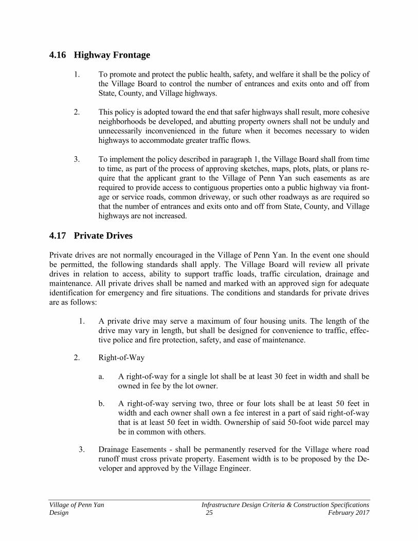
Village of Penn Yan Infrastructure Design Criteria & Construction Specifications
Design 25 February 2017
4.16 Highway Frontage 1. To promote and protect the public health, safety, and welfare it shall be the policy of
the Village Board to control the number of entrances and exits onto and off from State, County, and Village highways.
2. This policy is adopted toward the end that safer highways shall result, more cohesive
neighborhoods be developed, and abutting property owners shall not be unduly and unnecessarily inconvenienced in the future when it becomes necessary to widen highways to accommodate greater traffic flows.
3. To implement the policy described in paragraph 1, the Village Board shall from time
to time, as part of the process of approving sketches, maps, plots, plats, or plans re-quire that the applicant grant to the Village of Penn Yan such easements as are required to provide access to contiguous properties onto a public highway via front-age or service roads, common driveway, or such other roadways as are required so that the number of entrances and exits onto and off from State, County, and Village highways are not increased.
4.17 Private Drives
Private drives are not normally encouraged in the Village of Penn Yan. In the event one should be permitted, the following standards shall apply. The Village Board will review all private drives in relation to access, ability to support traffic loads, traffic circulation, drainage and maintenance. All private drives shall be named and marked with an approved sign for adequate identification for emergency and fire situations. The conditions and standards for private drives are as follows:
1. A private drive may serve a maximum of four housing units. The length of the drive may vary in length, but shall be designed for convenience to traffic, effec-tive police and fire protection, safety, and ease of maintenance.
2. Right-of-Way
a. A right-of-way for a single lot shall be at least 30 feet in width and shall be owned in fee by the lot owner.
b. A right-of-way serving two, three or four lots shall be at least 50 feet in width and each owner shall own a fee interest in a part of said right-of-way that is at least 50 feet in width. Ownership of said 50-foot wide parcel may be in common with others.
3. Drainage Easements - shall be permanently reserved for the Village where road runoff must cross private property. Easement width is to be proposed by the De-veloper and approved by the Village Engineer.
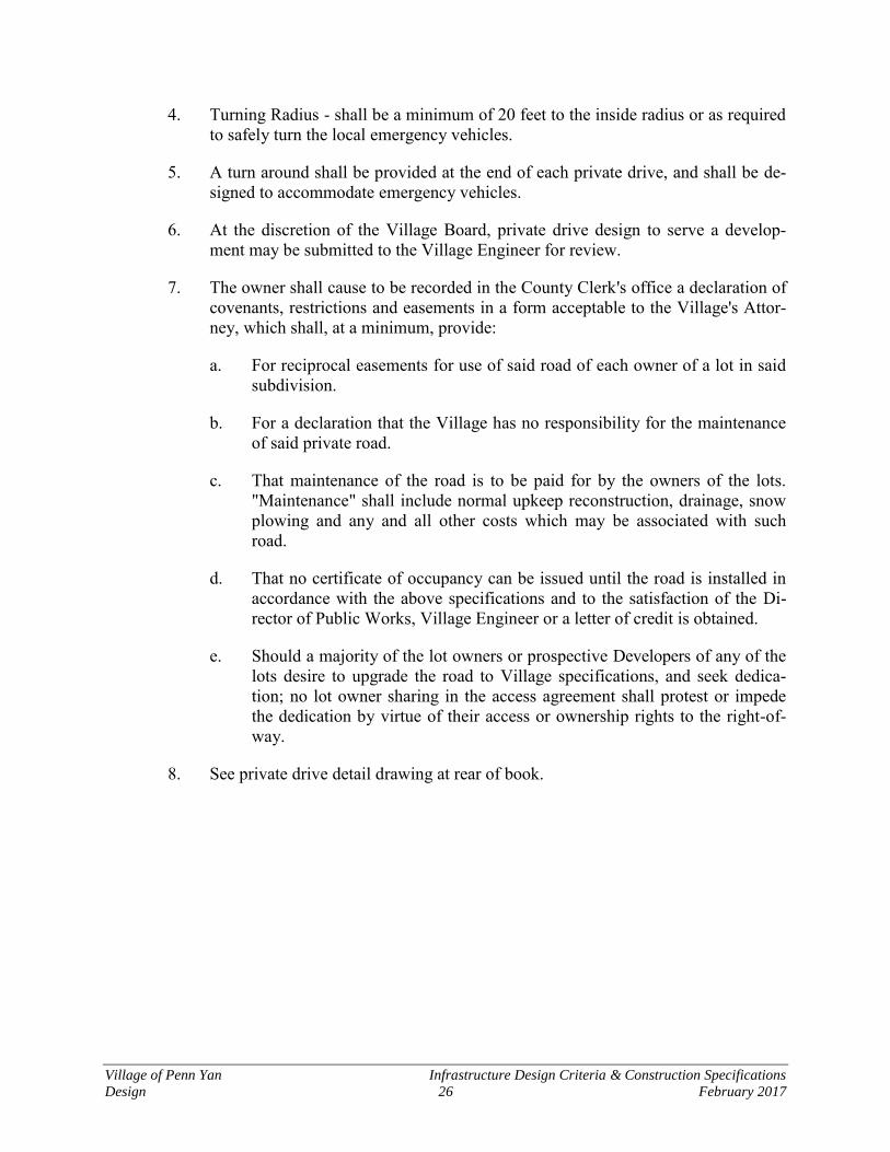
Village of Penn Yan Infrastructure Design Criteria & Construction Specifications
Design 26 February 2017
4. Turning Radius - shall be a minimum of 20 feet to the inside radius or as required to safely turn the local emergency vehicles.
5. A turn around shall be provided at the end of each private drive, and shall be de-signed to accommodate emergency vehicles.
6. At the discretion of the Village Board, private drive design to serve a develop-ment may be submitted to the Village Engineer for review.
7. The owner shall cause to be recorded in the County Clerk's office a declaration of covenants, restrictions and easements in a form acceptable to the Village's Attor-ney, which shall, at a minimum, provide:
a. For reciprocal easements for use of said road of each owner of a lot in said subdivision.
b. For a declaration that the Village has no responsibility for the maintenance of said private road.
c. That maintenance of the road is to be paid for by the owners of the lots. "Maintenance" shall include normal upkeep reconstruction, drainage, snow plowing and any and all other costs which may be associated with such road.
d. That no certificate of occupancy can be issued until the road is installed in accordance with the above specifications and to the satisfaction of the Di-rector of Public Works, Village Engineer or a letter of credit is obtained.
e. Should a majority of the lot owners or prospective Developers of any of the lots desire to upgrade the road to Village specifications, and seek dedica-tion; no lot owner sharing in the access agreement shall protest or impede the dedication by virtue of their access or ownership rights to the right-of-way.
8. See private drive detail drawing at rear of book.
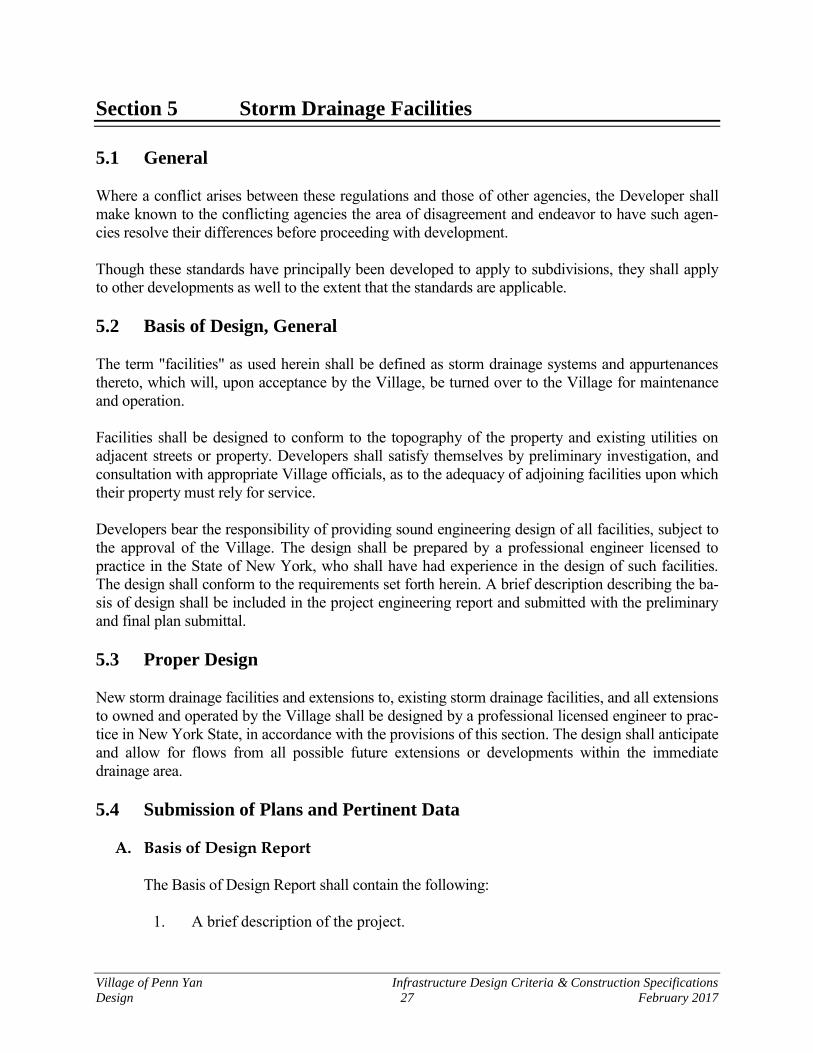
Village of Penn Yan Infrastructure Design Criteria & Construction Specifications
Design 27 February 2017
Section 5 Storm Drainage Facilities
5.1 General Where a conflict arises between these regulations and those of other agencies, the Developer shall make known to the conflicting agencies the area of disagreement and endeavor to have such agen-cies resolve their differences before proceeding with development. Though these standards have principally been developed to apply to subdivisions, they shall apply to other developments as well to the extent that the standards are applicable. 5.2 Basis of Design, General The term "facilities" as used herein shall be defined as storm drainage systems and appurtenances thereto, which will, upon acceptance by the Village, be turned over to the Village for maintenance and operation. Facilities shall be designed to conform to the topography of the property and existing utilities on adjacent streets or property. Developers shall satisfy themselves by preliminary investigation, and consultation with appropriate Village officials, as to the adequacy of adjoining facilities upon which their property must rely for service. Developers bear the responsibility of providing sound engineering design of all facilities, subject to the approval of the Village. The design shall be prepared by a professional engineer licensed to practice in the State of New York, who shall have had experience in the design of such facilities. The design shall conform to the requirements set forth herein. A brief description describing the ba-sis of design shall be included in the project engineering report and submitted with the preliminary and final plan submittal. 5.3 Proper Design New storm drainage facilities and extensions to, existing storm drainage facilities, and all extensions to owned and operated by the Village shall be designed by a professional licensed engineer to prac-tice in New York State, in accordance with the provisions of this section. The design shall anticipate and allow for flows from all possible future extensions or developments within the immediate drainage area. 5.4 Submission of Plans and Pertinent Data
A. Basis of Design Report
The Basis of Design Report shall contain the following:
1. A brief description of the project.

Village of Penn Yan Infrastructure Design Criteria & Construction Specifications
Design 28 February 2017
2. A description and map (USGS) of the drainage area on-site and adjacent to the site from which stormwater flows into and through the project site.
3. A soils map, including, when appropriate, soil borings necessary for the design and construction of ponds and/or infiltration devices.
4. A drawing showing the 100 year floodplain where applicable.
5. A description of the engineering criteria used in the design of the project.
6. A description of the hydrologic considerations including:
Tributary drainage areas delineated on a map; Calculated times of concentration; Rainfall intensity; Runoff coefficients; Design flows; A discussion of the pre- and post-development runoff conditions.
7. A summary with supporting calculations for the design of facilities to be con-
structed including but not limited to pipes, swales, drainage channels, ponds, and related facilities.
B. Plans and Support Documents
1. Plans of Sewers
a. Detail Plans: Detail plans shall be submitted. Profiles should have a hori-zontal scale of not more than 50 feet to the inch and a vertical scale of not more than 10 feet to the inch. Plan views should be drawn to a correspond-ing horizontal scale to the profile. Plans and profiles shall show:
1) Location of streets and sewers;
2) Line of ground surface; size, material, and type of pipe; length be-tween manholes; invert and surface elevation at each manhole; and grade of pipe between each two adjacent manhole (all manholes shall be numbered on the profile) and the elevation and location of the first floor shall be plotted on the profile of the sewer for all buildings to be served.
3) Locations of all special features.
4) All known existing structures and utilities, both above and below
ground, which might interfere with the proposed construction, or par-ticularly water mains and water supply structures, gas mains, sanitary sewers, and telephone and power conduits;

Village of Penn Yan Infrastructure Design Criteria & Construction Specifications
Design 29 February 2017
5) Detailed plans of all drainage provisions, proposed work, vegetative practices, erosion, and sediment control measures consistent with those practices recommended in the latest version of the New York State Guidelines for Urban Erosion and Sedimentation Controls;
6) Special detail drawings, made to a scale to clearly show the nature of
the design, shall be furnished to show the following particulars:
a) All stream crossings and sewer outlets, with elevations of the stream bed and normal and extreme high and low water levels;
b) Details of all special sewer joints and cross-sections; and c) Details of all storm sewer appurtenances such as manholes, in-
lets, etc.
2. Specifications
Complete technical specifications shall be submitted for the construction of sewers and all other appurtenances, and shall accompany or be part of the plans and details. The specifications shall include, but not be limited to, all construction information not shown on the drawings which is necessary to inform the contractor in detail of the design requirements for the quality of materials, workmanship, and fabrication of the project. The specifications shall also include: the type and size of pipe, construction materi-als; special filter materials, such as stone, sand, gravel, or slag; miscellaneous appurtenances; instructions for testing materials and equipment as necessary to meet design standards; and performance tests for the completed works and component units.
3. Revisions to Approved Plans
Any deviations from approved plans or specifications affecting capacity, flow, or point of discharge shall be approved, in writing, before such changes are made. Plans or specifications so revised should, therefore, be submitted well in advance of any construction work which will be affected by such changes to permit sufficient time for review and approval. Structural revisions or other minor changes not affect-ing capacities, flows, or operation will be permitted during construction without approval. "As-built" plans clearly showing such alterations shall be submitted at the completion of the work.
5.5 Purpose and Intent It is the purpose and intent of this section to protect the Village and its residents from adverse effects of stormwater runoff caused by the modification of any existing drainage system during construction or development on one or more parcels of land.

Village of Penn Yan Infrastructure Design Criteria & Construction Specifications
Design 30 February 2017
The adverse effects may include but are not limited to the following:
Increased rate of storm drainage runoff Soil movement and erosion Decreased water quality Sediment accumulation Decrease in soil absorption rate Decrease in existing water quality of creeks, streams, rivers and any other body of
water within the Village Increase in peak flows, volume, velocity and water concentration Obstruction of creeks, streams, rivers, and any other body of water within the Vil-
lage 5.6 General Requirements
1. The design and construction of drainage systems shall be such that the natural wa-tercourses traversing the development will be preserved wherever possible without adversely affecting the overall runoff rate, quantity, or water quality in addition to any improvements, existing or proposed buildings downstream or ad-jacent to the development. Off-site drainage water entering the development shall be received and discharged at locations and in a manner consistent with the natu-ral drainage patterns. The discharge flow at the downstream area of the development shall be contained in drainage facilities so that the flow effect will be returned to predevelopment conditions prior to leaving the development area or in a reasonable distance.
2. Natural drainage patterns shall be preserved and is preferable to realigning,
rechanneling streams or watercourses. No work shall be performed which directly or indirectly affects the natural patterns without the approval of the Village, County, State or Federal agency having jurisdiction.
3. No chemicals, fuels, lubricants, sewage or other pollutants shall be discharged in-
to any drainage system. 4. Fill or refuse shall not be deposited on any wetland, floodplain or drainage system
without the approval of the agency having jurisdiction. 5. No man-made structures shall block or restrict natural drainage patterns unless
permitted by the Village and / or other Agencies having jurisdiction. 6. Surface drainage shall be maintained during construction to prevent soil and sed-
iment from washing across or upon another property.
7. Drainage systems and stormwater sewer capacity shall be designed to handle the anticipated flows from the entire drainage basin when fully developed according to the existing zoning.

Village of Penn Yan Infrastructure Design Criteria & Construction Specifications
Design 31 February 2017
8. Sedimentation basins shall be employed as required by the Village and / or other
Agencies having jurisdiction to prevent siltation of downstream facilities or natu-ral water courses.
9. Surface waters and drainage shall not be altered or revised, except with approval
of the Village, where identified as being significant source of groundwater replen-ishment for the purpose of a potable water supply.
10. The New York State Department of Environmental Conservation has been ap-
proved by the United States Environmental Protection Agency to administer its State Pollution Discharge Elimination System (SPDES) program. Any new devel-opment project which disturbs one acre or more is subject to the requirements of the New York State Department of Environmental Conservation SPDES General Permit for Stormwater Discharges from Construction Activity Permit No. GP-0-15-002 or current revision. Evidence of compliance with the requirements of this permit must be submitted to the Village as a condition of Village approval.
5.7 Design of Drainage Systems
A. Hydrologic
1. The design of natural watercourse channels shall depend upon the drainage area according to the following table.
Design Return Intervals for Natural Watercourses
Drainage Area Recurrence Interval Above 20 sq. mi. 100 years Between 4 and 20 sq. mi. 50 years Less than 4 sq. mi. 25 years
2. Storm sewers and other hydraulic structures and channels shall be sized based up-on a design flow with a minimum return interval of 10 years.
3. The capacity of a drainage channel within a development shall be based upon
both the existing and anticipated rate of urbanization within the development wa-tershed and the type of development possible. Wherever a development may be located within a watershed in the initial stages of development, the proposed drainage system shall be designed to adequately pass the flows that would be gen-erated from continued development within the watershed. Wherever a development is located within a watershed in the advanced stages of development the system shall be designed and constructed to pass the project design flow de-termined for the ultimate urbanization of the tributary watershed. Storage basins

Village of Penn Yan Infrastructure Design Criteria & Construction Specifications
Design 32 February 2017
may be provided to increase the capacity of the drainage system and attenuate flows to downstream structures so that the capacities will not be exceeded. a. Two types of drainage basins may be constructed. A detention basin,
drained by gravity through a control-sized pipe located at the downstream end of the detention basin.
b. A retention basin allows for storage of stormwater runoff with release via evaporation or infiltration. Storage basins may be sized to accept exces-sive flow over and above the capacity of downstream drainage facilities and be used to improve flows through a proposed development or from a proposed development.
c. Parameters or rules regarding the stormwater discharge from a detention facility are as follows: The rate of discharge from a developed area shall not exceed the rate of discharge under the natural undeveloped conditions for all storm events.
4. For undeveloped areas of the tributary watershed, the percentage of surface classi-
fication shall be based upon land use, zoning and soil maps and correlated with projected land uses. Wherever a development watershed contains extensive per-manent open land uses such as railroads, public parks, cemeteries and parkways such factors may be additionally considered in determining an appropriate coeffi-cient of runoff.
5. The Hydrologic Design shall conform to the latest professional manuals, tables
and figures dealing with the many facets of stormwater systems. A number of methods can be used to estimate volume and peak runoff rates such as the Ration-al Method, SCS TR-20, and SCS TR-55. Other methods are acceptable with proper documentation.
6. The rainfall-intensity curves included in Figures 1 and 2 may be used for compu-
ting anticipated rainfall. The coefficient of runoff for various surface types shall be selected from the following table:
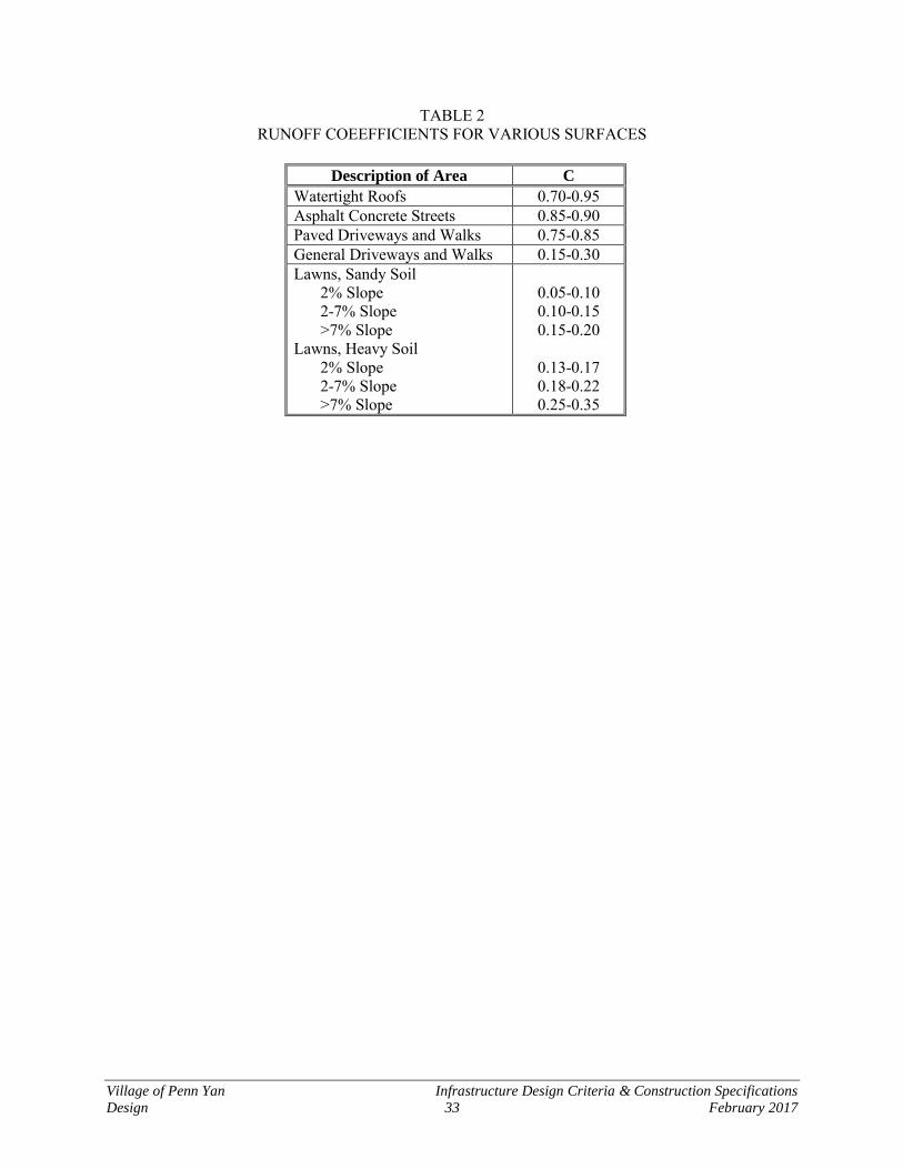
Village of Penn Yan Infrastructure Design Criteria & Construction Specifications
Design 33 February 2017
TABLE 2 RUNOFF COEEFFICIENTS FOR VARIOUS SURFACES
Description of Area C
Watertight Roofs 0.70-0.95 Asphalt Concrete Streets 0.85-0.90 Paved Driveways and Walks 0.75-0.85 General Driveways and Walks 0.15-0.30 Lawns, Sandy Soil 2% Slope 2-7% Slope >7% Slope Lawns, Heavy Soil 2% Slope 2-7% Slope >7% Slope
0.05-0.10 0.10-0.15 0.15-0.20
0.13-0.17 0.18-0.22 0.25-0.35
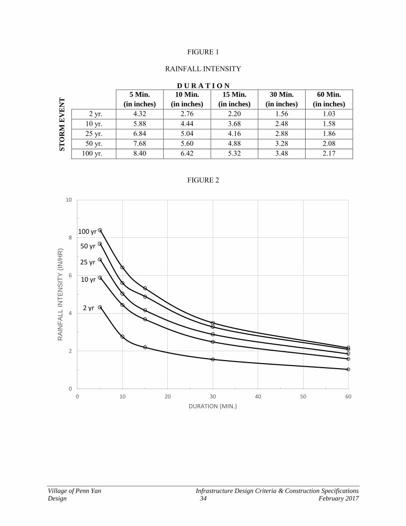
Village of Penn Yan Infrastructure Design Criteria & Construction Specifications
Design 34 February 2017
FIGURE 1
RAINFALL INTENSITY
D U R A T I O N
ST
OR
M E
VE
NT
5 Min. 10 Min. 15 Min. 30 Min. 60 Min.
(in inches) (in inches) (in inches) (in inches) (in inches)
2 yr. 4.32 2.76 2.20 1.56 1.03 10 yr. 5.88 4.44 3.68 2.48 1.58 25 yr. 6.84 5.04 4.16 2.88 1.86 50 yr. 7.68 5.60 4.88 3.28 2.08
100 yr. 8.40 6.42 5.32 3.48 2.17
FIGURE 2
0
2
4
6
8
10
0 10 20 30 40 50 60
RA
INF
ALL I
NT
EN
SIT
Y (
IN/H
R)
DURATION (MIN.)
2 yr
10 yr
25 yr
50 yr
100 yr
Village of Penn Yan Infrastructure Design Criteria & Construction Specifications
Design 35 February 2017
7. A coefficient of runoff of 0.20 is the maximum that shall be used for existing
conditions. For residential subdivisions, the coefficient of runoff shall not be less than 0.40 minimum.
8. For developments that require a permit under the State Pollutant Discharge Elimi-
nation System General Permit for stormwater discharges, the following volume requirements must be determined and mitigated: Water Quality Volume, Channel Protection Volume, Overbank Flood Volume and Extreme Storm Volume. Please see the New York Stormwater Management Design Manual to determine where these conditions do not apply and / or contact the NYSDEC.
B. Hydraulic
1. Hydraulic Design – The hydraulic design shall be performed in accordance with the hydrologic criteria specified herein and in accordance with modern standard procedures, endorsed by the American Society of Civil Engineers. The ultimate stormwater control capacity volume shall be based upon the design recurrence in-terval with the discharge rate from the structure’s outfall not exceeding the criteria set forth as follows:
Control of the peak discharge from the developed 1-year storm event to the 1-year predevelopment rate.
Control of the peak discharge from the developed 10-year storm event to the 10-year predevelopment rate.
Control of the peak discharge from the developed 100-year storm event to the 100-year predevelopment rate.
In addition, for those sites that meet the State Pollutant Discharge Elimination System General Permit criteria for stormwater discharges, the Water Quality Vol-ume shall be determined based on the 90% rule. That is the Water Quality Volume is designed to improve water quality sizing to capture and treat 90% of the average annual stormwater runoff volume. (Refer to New York Stormwater Management Design Manual for additional information.)
2. The outlet structure for the stormwater control facility shall uniformly regulate the
discharge of stormwater runoff throughout all storm events. The design structure shall consistently control the difference between the pre- and post-development runoff for all storm events.
3. The hydraulic design shall conform to the latest professional manuals, tables and
figures dealing with the many facets of stormwater systems, including water qual-ity management measures as defined by the NYSDEC.
4. The hydraulic design of all closed drainage systems shall conform to the latest
professional manuals that will substantiate and integrate proven hydraulic princi-pals and basic assumptions. Open and closed drainage systems shall be designed

Village of Penn Yan Infrastructure Design Criteria & Construction Specifications
Design 36 February 2017
to provide complete drainage for all elements within the development (roadways, yards, open space, etc.). The size of the pipes with a closed drainage system shall be designed to provide capacity for a 10 year storm event and produce a minimum velocity of three (3) feet per second when flowing full. The minimum pipe size shall have a 12-inch diameter.
5. A detailed grading plan shall be provided with a contour interval suitable for the
map scale. The map shall provide for surface drainage for all lots within the de-velopment and adjacent land.
C. Criteria
All catch basins, manholes, inlets and other items placed within a development shall con-form to the standards approved by the Village. The structural design of all drainage items shall be subject to the approval by the Village and conform to the standard specifications adopted by the Village.
1. Channels – The minimum bottom width of channels shall be three feet. The crea-
tion of excessive number of curves in open channels shall be avoided to protect against excessive erosion. The Village reserves the right to require bank protec-tion. Earth channels shall have a minimum side slope of one to three (1 vertical: 3 horizontal) or flatter, unless otherwise approved by the Village (or the Village’s representative).
2. Enclosed conduits/drainage systems – Except for adequate natural watercourses,
all storm drainage within the development shall be conveyed in a pipe system having an “N” value of 0.013 and a maximum pipe diameter of 48 inches. The Developer and their engineers bear the responsibility of providing technical de-sign data in this regard and shall be submitted to the Village and/or their approval representative.
3. Drainage Systems – The minimum pipe size shall be 12 inches. An “N” of 0.013
shall be used for smooth pipe. No metal pipes shall be allowed. Manholes shall be provided at all grade and direction changes. The maximum space between drain-age structures shall be 300 feet with the minimum cover of conduits as required by the specific manufacturer. Systems shall be designed using a straight-line grade and alignment between manholes.
4. Manhole tops shall be accurately designed to conform to finished grade. 5. All three-way manholes shall have a minimum diameter of 5 feet. The invert of a
three-way manhole will have a minimum horizontal radius equal to one-half the diameter of the manhole for the branch flow. No “T” intersections will be al-lowed.
6. Developers and their engineers shall design the vertical control of the subdivision
so that surcharge of storm drainage systems will not cause a backup or flooding of

Village of Penn Yan Infrastructure Design Criteria & Construction Specifications
Design 37 February 2017
cellars. This will require that cellars drains not be connected to the storm drainage system.
7. Storm drains conveying drainage along any side lot lines shall extend to the rear
lot line or to the main channel to which the drain discharging.
D. Stormwater Detention Basins
1. The Village has determined that stormwater detention/retention ponds are re-quired to prevent downstream natural watercourses from being over taxed and prevent excessive erosion.
2. The stormwater control capacity volume shall be based upon the design recur-rence interval with the discharge rate from the structure’s outfall not exceeding the criteria set forth as stated above.
3. The Village reserves the right to establish other more restrictive parameters. For example, if the downstream area has been subjected to floods in the past, even while the upstream areas were not developed, and if the Village deems it desirable and appropriate to remedy this situation, they may, at the Village’s discretion re-quired an impoundment area of a size and type as well as storm sewers and culverts, which can assist in rectifying the downstream flooding situation. Down-stream flooding may include flooded backyards or overtaxed downstream piping systems.
4. The following parameters shall be following regarding stormwater discharge:
a. The rate of discharge from developed area shall not exceed the rate of dis-charge under natural undeveloped conditions for all storm events as defined above.
b. The rate of discharge shall be reduced further if in the opinion of the Vil-lage, the downstream streams/channels would otherwise be subjected to potential overflow, erosion, or siltation as a result of runoff from the devel-opment.
c. The Village reserves the right to request the Developer to improve swales, ditches, or channels immediately downstream of the development. The preservation and improvement of stream and channels downstream shall be permitted on a case-by-case basis for situations where downstream facilities are inadequate, or where a reduction in the rate of discharge is not practical. The Developer shall submit detailed information on proposed preservation and improvement methods.
d. Engineering Procedures – Detention Basin Design – The following methods for detention basin hydrology calculations are acceptable for design: SCS TR-55 “Urban Hydrology for Small Watersheds”, Rational Method or Mod-
Village of Penn Yan Infrastructure Design Criteria & Construction Specifications
Design 38 February 2017
ified Rational Method, or SCS TR-20 “Project Formulation Hydrology”. Other methods are acceptable with proper documentation. The following in-formation shall be included in the design:
1) Inflow hydrograph shall be determined for pre-developed and post-
developed conditions for each design storm. 2) The volume of storage shall be estimated based on design discharge
rate. 3) Selection of the outlet structure that limits the discharge to the pre-
developed rate or less for each design storm event. 4) The facility shall be designed in a manner that does not cause inunda-
tion upstream during the high water ponding levels. 5) The detention facility shall be provided with an emergency spillway
capable of passing the 100-year storm event. 6) The downstream pathway of the detention facility and spillway shall
be investigated to insure that the pathway has sufficient overflow ca-pacity to prevent impacts on adjacent dwellings.
7) All ponds shall have trickle tube risers designed as follows: a) Minimum diameter of 36 inches. b) Maximum height of 6 feet. c) Riser shall be as high as outflow pipe. d) Trash rack shall be designed for placement on top of riser. e) Emergency spillway shall pass the 100-year storm event at a
maximum flow depth of 0.5 feet. f) Rip-rap shall be provided as a lining for the emergency spill-
way. g) Top of berm shall be 1.5 feet above emergency spillway eleva-
tion. h) The bottom of the pond shall be sloped at a minimum of 0.50%. i) The pond berm shall consist of select fill (NYSDOT Item
203.05) as defined by NYSDOT 203-2 except that no material shall be larger than 4 inches in the maximum dimension, and shall be compacted in 6 inch layers in accordance with NYSDOT 203-3.12.
j) Topsoil shall be removed prior to berm placement. k) Seepage collars or an approved equivalent method shall be used
to prevent piping of water along the outside of the outflow pipe. A minimum of two seepage collars shall be provided around the outflow pipe.
l) Maximum pond side slopes shall be 1V : 3H. m) Unusual topographic conditions may warrant changes in the
pond geometry and discharge structure and should be approved by the Village.
Village of Penn Yan Infrastructure Design Criteria & Construction Specifications
Design 39 February 2017
5.8 Erosion and Sedimentation Control In order to assure that the surrounding land and watercourses will not be subjected to siltation or erosion the Village shall require the Developer to follow certain guidelines. The following is a list of procedures that may be required:
1. Installing and maintaining temporary sedimentation basins at the point or points of stormwater discharge from the property.
2. The area of clearing and grubbing, excavation, borrow and embankment opera-
tions in progress shall commensurate with the Developers capability and progress in keeping the finished grading, mulching, seeding and other temporary and/or permanent control measures.
3. Provisions for temporary vegetation and/or mulching.
4. Provide provisions for adequate drainage facilities to effectively accommodate the
increased runoff caused by changed soil and surface conditions.
5. Retain and protect existing natural vegetation.
6. Install permanent final vegetation and structures as soon as possible.
7. Provide adequate protective measures along steep slopes and along swales, ditch-es, etc.
8. Other procedures as defined in the “New York Guidelines for Urban Erosion and
Sedimentation Controls” shall be required as defined by the Village or the Vil-lage’s representative.
5.9 Water Quality For those sites that meet the NYSDEC SPDES General Permit criteria for regulation of storm-water discharges, the stormwater management practices described in Chapter 7 of the 2015 New York State Stormwater Management Design Manual, or latest release, are acceptable to the NYSDEC for water quality treatment. The Village does not currently require that stormwater quality treatment practices in excess of those described in this section be implemented. However, evidence of compliance with the requirements of the NYSDEC’s SPDES General Permit must be submitted to the Village as a condition of Village approval. 5.10 Drainage Easements
1. Closed Drainage Systems – An easement of not less than twenty (20) feet in width shall be provided to contain the enclosed drainage system and provide working space for personnel and equipment for service of enclosed drainage system.
Village of Penn Yan Infrastructure Design Criteria & Construction Specifications
Design 40 February 2017
Easements shall be placed along or adjacent to lot boundary lines and in a straight alignment. Easements shall be indicated on a map of the development and desig-nated as follows “Drainage Easement to the Village of Penn Yan”.
2. Constructed Channels – Channels constructed within the a development shall
have enough easement dedicated to contain the top width of the channel plus a minimum twenty-foot continuous work space along one side of the channel for channels less than twenty feet in width. For channel widths greater than twenty feet, the easement shall be provided for the top width of the channel as well as twenty foot work areas along both sides of the channel. Easements shall be indi-cated on a map of the development and designed as follows “Drainage Easement to the Village of Penn Yan”.
5.11 Flood Hazard Prevention Flood Hazard prevention shall include the control of soil erosion of land surface and drainage channels and the prevention of inundation and excessive ground water seepage by comprehen-sive site grading and the establishment of adequate elevations of buildings, building openings and roadways above the computed water levels of stormwater elements.
1. All proposed development within the Flood Hazard area defined by the Federal Emergency Management Agency (FEMA) shall comply with all regulations set forth by the Federal Insurance Administrator. In addition, all development must comply with the Village regulations.
2. Development within or adjacent to the floodplain shall comply with current Vil-
lage zoning, ordinances and regulations. Particular attention shall be paid to the development in the vicinity of Keuka Lake, Keuka Lake Outlet and its tributaries. No alteration of the existing characteristics of the areas shall take place without the specific approval of the Village as to the adequacy of the protective measures taken, in any, and the effects of such development on upstream and downstream reaches of the watercourse and adjacent properties.
Village of Penn Yan Infrastructure Design Criteria & Construction Specifications
Design 41 February 2017
Section 6 Sanitary Sewage Facilities
6.1 General Where a conflict arises between these regulations and those of other agencies, the Developer shall make known to the conflicting agencies the area of disagreement and endeavor to have such agen-cies resolve their differences before proceeding with development. Though these standards have principally been developed to apply to subdivisions, they shall apply to other developments as well to the extent that the standards are applicable. 6.2 Basis of Design, General The term "facilities" as used herein shall be defined as sanitary sewers and appurtenances thereto, which will, upon acceptance by the Village, be turned over to the Village for maintenance and oper-ation. Facilities shall be designed to conform to the topography of the property and existing utilities on adjacent streets or property. Developers shall satisfy themselves by preliminary investigation, and consultation with appropriate Village officials, as to the adequacy of adjoining facilities upon which their property must rely for service. Developers bear the responsibility of providing sound engineering design of all facilities, subject to the approval of the Village. The design shall be prepared by a professional engineer licensed to practice in the State of New York, who shall have had experience in the design of such facilities. The design shall conform to the requirements set forth herein. A brief description describing the ba-sis of design shall be included in the project engineering report and submitted with the preliminary and final plan submittal. 6.3 Proper Design New sanitary sewers and all extensions to sanitary sewers owned and operated by the Village shall be designed by a professional licensed engineer to practice in New York State, in accordance with the Recommended Standards for Wastewater Facilities, as adopted by Great Lakes-Upper Missis-sippi River Board (GLUMRB) of State Sanitary Engineers (Ten State Standards) latest revision, and in strict conformance with the NYSDEC, before initiating any construction. The design shall antici-pate and allow for flows from all possible future extensions or developments within the immediate drainage area. 6.4 Submission of Plans and Pertinent Data
A. Basis of Design Report The Basis of Design Report shall contain the following:
Village of Penn Yan Infrastructure Design Criteria & Construction Specifications
Design 42 February 2017
1. Flow and Organic Load: The anticipated design average and design peak flows and waste load for the existing and ultimate conditions must be established. The basis of the projection of initial and future flows and waste load must be included and must reflect the existing, or initial service area, and the anticipated future ser-vice area.
2. Impact on Existing Wastewater Facilities: The impact of the proposed project on all existing wastewater facilities, including gravity sewers, lift stations, and treat-ment facilities must be evaluated.
3. Project Description: A written description of the project is required.
4. Drawings: Drawings identifying the site of the project and anticipated location and alignment of proposed facilities are required.
5. Engineering Criteria: Engineering criteria to be used in design of the project shall be included.
6. Site Information: Project site information should include topography, soils, geo-logic conditions, depth to bedrock, groundwater level, floodway or floodplain considerations, and other pertinent site information.
7. Alternative Selection: The reasons for selection of the proposed alternative, in-cluding any lift station sites, feasibility, and how the project fits into a long-term plan, should be discussed.
B. Plans and Support Documents
1. Plans of Sewers
a. Detail Plans: Detail plans shall be submitted. Profiles should have a hori-zontal scale of not more than 50 feet to the inch and a vertical scale of not more than 10 feet to the inch. Plan views should be drawn to a correspond-ing horizontal scale to the profile. Plans and profiles shall show:
1) Location of streets and sewers;
2) Line of ground surface; size, material, and type of pipe; length be-tween manholes; invert and surface elevation at each manhole; and grade of sewer between each two adjacent manhole (all manholes shall be numbered on the profile) and the elevation and location of the first floor shall be plotted on the profile of the sewer for all buildings to be served. The Developer’s Engineer shall state that all sewers are suffi-ciently deep to serve all first floors;
3) Locations of all special features such as inverted siphons, concrete
encasements, etc.
Village of Penn Yan Infrastructure Design Criteria & Construction Specifications
Design 43 February 2017
4) All known existing structures and utilities, both above and below ground, which might interfere with the proposed construction or re-quire isolation setback, particularly water mains and water supply structures (i.e. wells, clear wells, basins), gas mains, storm drains, and telephone and power conduits;
5) Special detail drawings, made to a scale to clearly show the nature of
the design, shall be furnished to show the following particulars:
a) All stream crossings and sewer outlets, with elevations of the stream bed and normal and extreme high and low water levels;
b) Details of all special sewer joints and cross-sections; and c) Details of all sewer appurtenances such as manholes, lam-
pholes, clean outs, inspection chambers, inverted siphons, etc.
2. Plans of Sewage Pumping Stations
a. Detail Plans: Detail plans shall be submitted showing the following, where applicable:
1) Topography of the site; 2) Existing pumping station; 3) Proposed pumping station, including provisions for installation of fu-
ture pumps or ejectors; 4) Elevation of high water at the site, and maximum elevation of
wastewater in the collection system upon occasion of power failure; 5) Maximum hydraulic gradient in downstream gravity sewers when all
installed pumps are in operation; and 6) Test borings and groundwater elevations.
b. Specifications
Complete technical specifications shall be submitted for the construction of sewers, wastewater pumping stations, and all other appurtenances, and shall accompany the plans. The specifications accompanying construction drawings shall include, but not be limited to, all construction information not shown on the drawings which is necessary to inform the builder in detail of the design requirements for the quality of materials, workmanship, and fabrication of the project. The specifications shall also include: the type, size, strength, operating char-acteristics, and rating of equipment; allowable infiltration; the complete requirements for all mechanical and electrical equipment, including machin-ery, valves, piping, and jointing of pipe; electrical apparatus, wiring, instrumentation, and meters; operating tools, construction materials; special filter materials, such as stone, sand, gravel, or slag; miscellaneous appurte-
Village of Penn Yan Infrastructure Design Criteria & Construction Specifications
Design 44 February 2017
nances; instructions for testing materials and equipment as necessary to meet design standards; and performance tests for the completed works and com-ponent units.
c. Revisions to Approved Plans
Any deviations from approved plans or specifications affecting capacity, flow, operation of units, or point of discharge shall be approved, in writing, before such changes are made. Plans or specifications so revised should, therefore, be submitted well in advance of any construction work which will be affected by such changes to permit sufficient time for review and approv-al. Structural revisions or other minor changes not affecting capacities, flows, or operation will be permitted during construction without approval. "As-built" plans clearly showing such alterations shall be submitted at the completion of the work.
6.5 Design of Sewers
A. Details of Gravity Pipe Design
1. Minimum Size
No gravity sewer conveying raw wastewater shall be less than 8 inches (203 mm) in diameter.
2. Depth
Sewers should be sufficiently deep to receive wastewater from first floors or base-ments where practical, and to prevent freezing. Insulation shall be provided for sewers that cannot be placed at a depth sufficient to prevent freezing. Consideration shall also be given to the relationship of house elevation to sewer ele-vation to assure the installation of laterals on at least a one percent (1%) grade (1/8-inch per foot) for 6-inch laterals and (2%) grade (1/4-inch per foot) for 4-inch lat-erals.
3. Buoyancy
Buoyancy of sewers shall be considered and flotation of the pipe shall be prevented with appropriate construction where high groundwater conditions are anticipated.
4. Slope
a. Recommended Minimum Slopes
All sewers shall be assigned and constructed to give mean velocities, when flowing full, of not less than 2.0 feet per second based on Manning's formula
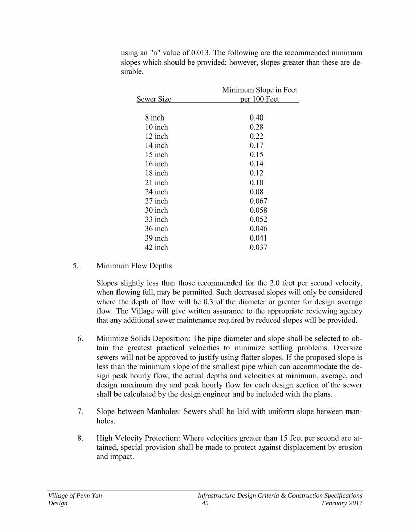
Village of Penn Yan Infrastructure Design Criteria & Construction Specifications
Design 45 February 2017
using an "n" value of 0.013. The following are the recommended minimum slopes which should be provided; however, slopes greater than these are de-sirable.
Minimum Slope in Feet Sewer Size per 100 Feet 8 inch 0.40 10 inch 0.28 12 inch 0.22 14 inch 0.17 15 inch 0.15 16 inch 0.14 18 inch 0.12 21 inch 0.10 24 inch 0.08 27 inch 0.067 30 inch 0.058 33 inch 0.052 36 inch 0.046 39 inch 0.041 42 inch 0.037
5. Minimum Flow Depths
Slopes slightly less than those recommended for the 2.0 feet per second velocity, when flowing full, may be permitted. Such decreased slopes will only be considered where the depth of flow will be 0.3 of the diameter or greater for design average flow. The Village will give written assurance to the appropriate reviewing agency that any additional sewer maintenance required by reduced slopes will be provided.
6. Minimize Solids Deposition: The pipe diameter and slope shall be selected to ob-
tain the greatest practical velocities to minimize settling problems. Oversize sewers will not be approved to justify using flatter slopes. If the proposed slope is less than the minimum slope of the smallest pipe which can accommodate the de-sign peak hourly flow, the actual depths and velocities at minimum, average, and design maximum day and peak hourly flow for each design section of the sewer shall be calculated by the design engineer and be included with the plans.
7. Slope between Manholes: Sewers shall be laid with uniform slope between man-holes.
8. High Velocity Protection: Where velocities greater than 15 feet per second are at-tained, special provision shall be made to protect against displacement by erosion and impact.
Village of Penn Yan Infrastructure Design Criteria & Construction Specifications
Design 46 February 2017
9. Steep Slope Protection: Sewers on 20 percent slopes or greater shall be anchored securely with concrete, or equal, anchors spaced as follows:
a. Not over 36 feet center to center on grades 20 percent and up to 35 percent;
b. Not over 24 feet center to center on grade 35 percent and up to 50 percent; and
c. Not over 16 feet center to center on grades 50 percent and over.
10. Alignment: Sewers shall be laid with straight alignment between manholes. Straight alignment shall be checked by either using a laser beam or lamping.
11. Changes in Pipe Size:
When a smaller sewer joins a larger one, the invert of the larger sewer should be lowered sufficiently to maintain the same energy gradient. An approximate method for securing these results is to place the 0.8 depth point of both sewers at the same elevation. Sewer extensions should be designed for projected flows even when the diameter of the receiving sewer is less than the diameter of the proposed extension at a manhole with special consideration of an appropriate flow channel to minimize turbulence when there is a change in sewer size.
12. Pipe Materials
Any of the following generally accepted materials for sewers will be given consider-ation, but the material selected should be adapted to local conditions, such as: character of industrial wastes, possibility of septicity, soil characteristics, exception-ally heavy external loadings, abrasion, corrosion, and similar problems. All sewers shall be designed to prevent damage from superimposed live, dead, and frost induced loads. Proper allowance for loads on the sewer shall be made because of soil and potential groundwater conditions, as well as the width and depth of trench. Where necessary, special bedding, haunching and initial backfill, concrete cradle, or other special construction shall be used to withstand anticipated potential superimposed loading or loss of trench wall stability. See ASTM D2321 or ASTM C 12 as appropriate. For new pipe materials for which ASTM standards have not been established, the design engineer shall provide complete pipe specifications and installation specifica-tions developed on the basis of criteria adequately documented and certified in writing by the pipe manufacturer to be satisfactory for the specific detailed plans.
Village of Penn Yan Infrastructure Design Criteria & Construction Specifications
Design 47 February 2017
a. Ductile Iron Pipe
1) Pipe a) Mechanical or push-on joints - AWWA C151, ANSI A21.51,
Grade 60-42-10, standard laying lengths, except for closures and specials, shall be a minimum of 18'.
b) Flanged joints - AWWA C115, ANSI 21.15. 2) Fittings - ANSI A21.10 (AWWA C110), MJ or MR as required, of
suitable and equal strength as the pipe, lined and coated as specified below.
3) Joints a) Mechanical - AWWA C111. b) Push-On/AWWA C111, "Tyton" as manufactured by U.S. Pipe
& Foundry Co., "Ball-Tite" as manufactured by Clow, or ap-proved equal.
c) Flanged - Specially designed long hub screw flanges, face drilled to ANSI B.16.1, Class 125 template for use with AW-WA C110 fittings. Flanges shall be shop assembled. Pipe barrels, and pipe ends shall be refaced after assembly, plain face, smooth finish. All pipe threads shall be covered by the flange. Gaskets shall be factory cut, 1/16 inch thick, flat ring, cloth inserted rubber conforming to ANSI B16.21, 125 pound cast iron joint. Bolts shall be carbon steel, ASTM A307, Grade A, square head machine bolts with heavy steel hexnut. Bolt size and length shall conform to ANSI B16.1 for 125 pound cast iron joints, plain face, smooth finish.
d) Mechanical, Restrained - AWWA C111, except, provide me-chanical joint retainer gland with set screws in lieu of follower gland.
4) Class - Mechanical or push-on pipe shall be Class 51 or thicker. Flanged pipe shall be Class 53.
5) Lining a) Bituminous per AWWA C151. b) Cement Mortar with bituminous seal coat per AWWA C104. c) Coatings - Bituminous per AWWA C151.
b. Polyvinyl Chloride Pipe (PVC) Non-Pressure Piping (Gravity Sanitary Sew-
er)
1) Pipe and Pipe Fittings - Exterior Smooth Pipe
a) Acceptable Products - As manufactured by CertainTeed, Johns-Manville, Clow Corp., or approved equal.
b) Materials - PVC pipe and fittings to be used for gravity sewer shall fully conform to the requirements of ASTM D-3034 "Type PSM Poly (vinyl chloride) (PVC) sewer pipe and fittings", latest revision. Pipe and fittings shall also meet or exceed the re-
Village of Penn Yan Infrastructure Design Criteria & Construction Specifications
Design 48 February 2017
quirements of Uni-Bell UNI-B-5 recommended standard for in-tegral, gasketed joint PVC sewer pipe and fittings. Standard diameter ratios (SDR) shall be as shown on the Contract Draw-ings. Pipe for sewer mains shall be SDR-35 PVC.
c) The pipe and pipe fittings shall also be made of PVC plastic having a cell classification of 12454-B, or 12454-C, or 13364-B as defined in ASTM D 1784.
d) The pipe shall not disintegrate or flake when tested (this does not replace any other testing) in accordance with ASTM D-2152.
e) The pipe shall meet impact resistance in accordance with ASTM D-2444.
f) The minimum pipe stiffness at 5% deflection shall be 46 psi when tested in accordance with ASTM D-2412.
g) Standard laying length shall be 20 feet. Random lengths of less than 20 feet may be utilized to make proper connections.
h) Pipe shall be green in color.
c. Joints
1) The pipe shall be joined with an integral bell, bell and spigot type rubber gasketed joint. Each integral bell joint shall consist of a formed bell complete with one or more rubber gaskets. Gaskets shall conform to ASTM D-1869 and ASTM F477. The gasket shall be locked se-curely in place by a groove formed in the bell to present displacement during assembly. The "locked-in" rubber seating ring shall also meet or exceed the requirements of ASTM D-3212 - Joints for Drain and Sewer Pipes Using Flexible Elastomeric Seals. Pipe with gaskets held in place by only glue will not be acceptable.
2) Each spigot end shall be clearly marked, for the entire circumference, indicating the proper distance of insertion into the adjoining bell end, such marking being placed so as to adequately allow for expansion and contraction of the pipeline over the full range of temperature fluc-tuations which may occur in the final installation. The sealing ring shall be the only element depended on to make the joint flexible and watertight.
3) Joint lubricant shall be as recommended by the manufacturer.
d. PVC Laterals
1) Materials a) Polyvinyl Chloride Pipe: Polyvinyl chloride pipe and fittings
shall have bell and spigot joints with flexible elastomeric gas-kets for short-side laterals. Long-side lateral joints can be glued. SDR-35 pipe and fittings shall conform to ASTM D2241, with joints conforming to ASTM D3139 and F477.
Village of Penn Yan Infrastructure Design Criteria & Construction Specifications
Design 49 February 2017
e. Miscellaneous Materials
1) Caps and Plugs a) Watertight, of similar manufacturer and producing the same
joint conditions as the pipe on which the cap or plug is placed. 2) Bulkheads
a) Watertight brick masonry, 8-inch thick minimum. 3) Foundation Materials
a) Gravel or crushed stone bedding shall be as detailed. b) Select earth backfill shall be as detailed.
4) Pipe Adapters: Join pipes of different materials with adapters specifi-cally manufactured for that purpose. Where dissimilar materials join, such that galvanic action may produce corrosion, provide dielectric couplings to preclude damage to the materials.
5) Stubs: Of the same material as the pipe, 5 feet long. Plug the stubs with suitable, approved plugs or caps specifically made for the pur-pose. Plugs and caps shall be watertight and installed so as to be readily removable without damage to the pipe when future connec-tions are made.
B. Details of Pressure Pipe Design
1. Velocity and Diameter
At design pumping rates, a cleansing velocity of at least 2 feet per second should be maintained. The minimum force main diameter for raw wastewater shall be 4 inches.
2. Air and Vacuum Relief Valve
An air relief valve shall be placed at high points in the force main to prevent air locking. Vacuum relief valves may be necessary to relieve negative pressures on force mains. The force main configuration and head conditions should be evaluated as to the need for and placement of vacuum relief valves.
3. Termination
Force mains should enter the gravity sewer system at a point not more than 2 feet above the flow line of the receiving manhole.
4. Pipe and Design Pressure
Pipe and joints shall be equal to water main strength materials suitable for design conditions. The force main, reaction blocking, and station piping shall be designed to withstand water hammer pressures and associated cyclic reversal of stresses that are expected with the cycling of wastewater lift stations. Surge protection chambers should be evaluated.
Village of Penn Yan Infrastructure Design Criteria & Construction Specifications
Design 50 February 2017
5. Design Friction Losses
a. Friction losses through force mains shall be based on the Hazen and Wil-liams formula (utilizing a "C" factor) or other acceptable methods.
b. Maximum Power Requirements
1) When initially installed, force mains will have a significantly higher "C" factor. The effect of the higher "C" factor should be considered in calculating maximum power requirements and duty cycle time to pre-vent damage to the motor.
6. Identification: Where force mains are constructed of material which might cause
the force main to be confused with potable water mains, the force main shall be appropriately identified.
7. Ductile Iron Pipe and Fittings
a. All pipe and fittings shall be of good quality, strong, of even grain, and soft enough to permit drilling and cutting. Each pipe shall be free from any de-fects which would make it unfit for the use intended. All pipe shall be straight and be a true circle in section with concentric inner and outer sur-faces. Pipe to be cut during installation shall be fully gauged for field cutting. Pipe metal shall be made without any admixture of cinder iron or other inferior material.
b. Pipe shall be ductile iron pipe conforming to the requirements of ANSI A21.51 (AWWA C151). Pipe class thickness shall be Class 52.
c. Fittings shall be gray iron or ductile iron fittings conforming to the require-ments of ANSI/AWWA C110. Fittings shall equal or exceed the requirements of the main pipe and shall have a rated working pressure of 250 psi.
d. Pipe and pipe fittings shall be cement-mortar lined (double thickness) in ac-cordance with the requirements of ANSI/AWWA C104/A21.4, with an asphalt coating on the outside of the pipe.
e. Joints shall be rubber gasket push-on, mechanical joint anchoring, or flange joint type. All joints shall conform to the requirements of ANSI/AWWA C111/A21.11. Electrical conductivity for push-on joints shall be maintained by the use of bronze wedges (two per joint for pipe sizes up to 12-inch di-ameter; four per joint for all other pipe sizes). Rubber gaskets shall be used on mechanical joints.
f. Underground pipe shall have an external polyethylene encasement tube with taped joints.
Village of Penn Yan Infrastructure Design Criteria & Construction Specifications
Design 51 February 2017
8. Polyvinylchloride (PVC)
a. Materials: Polyvinyl chloride pipe and fittings shall have bell and spigot joints with flexible elastomeric gaskets. SDR-35 pipe and fittings shall con-form to ASTM D3034 Type PSM or ASTM F679 with joints conforming to ASTM D3212 and F477.
b. Reference: ASTM D1785 (current year) Pipe; ASTM D1787 (current year) Material.
c. The manufacturer's and supplier's certification that all materials furnished have passed the acceptance tests listed in the appropriate specifications shall be furnished.
C. Details of Manhole Design
1. Location: Manholes shall be installed at the end of each line, at all changes in grade, size, or alignment, at all intersections, and at distance not greater than 300 feet maximum. Cleanouts may be used only for special conditions and shall not be substituted for manholes nor installed at the end of laterals greater than 150 feet in length.
2. Drop Type
a. A drop pipe shall be provided for a sewer entering a manhole at an eleva-tion of 24 inches or more above the manhole invert. Where the difference in elevation between the incoming sewer and the manhole invert is less than 24 inches, the invert shall be filleted to prevent solids deposition.
b. Drop manholes should be constructed with an outside drop connection.
c. Due to the unequal earth pressures that would result from the backfilling operation in the vicinity of the manhole, the entire outside drop connection shall be encased in concrete.
3. Diameter: The flow channel straight through a manhole should be made to con-form as closely as possible in shape, and slope to that of the connecting sewers. The channel walls should be formed or shaped to the full height of the crown of the outlet sewer in such a manner to not obstruct maintenance, inspection, or flow in the sewers. When curved flow channels are specified in manholes, including branch inlets, minimum slopes should be increased to maintain acceptable veloci-ties.
4. Bench
a. A bench shall be provided on each side of any manhole channel when the pipe diameter(s) are less than the manhole diameter. The bench should be sloped no less than 1/2 inch per foot (4 percent). No lateral sewer, service
Village of Penn Yan Infrastructure Design Criteria & Construction Specifications
Design 52 February 2017
connection, or drop manhole pipe shall discharge onto the surface of the bench.
b. The invert of a three-way manhole shall have a minimum horizontal radius equal to one-half (1/2) the diameter of the manhole for the branch flow con-nection. No tee intersections will be permitted.
5. Watertightness
a. Manholes shall be of the precast concrete or poured-in-place concrete type. Manhole lift holes and grade adjustment rings shall be sealed with non-shrinking mortar.
b. Inlet and outlet pipes shall be joined to the manhole with a gasketed flexible watertight connection or any watertight connection arrangement that allows differential settlement of the pipe and manhole wall to take place.
c. Watertight manhole covers are to be used wherever the manhole tops may be flooded by street runoff or high water.
6. Inspection and Testing
The Developer's specifications shall include a requirement for inspection and testing for watertightness or damage prior to placing into service.
D. Inverted Siphons
Inverted siphons should have not less than two barrels, with a minimum pipe size of 6 inch-es. They shall be provided with necessary appurtenances for maintenance, convenient flushing, and cleaning equipment. The inlet and discharge structures shall have adequate clearances for cleaning equipment, inspection, and flushing. Design shall provide sufficient head and appropriate pipe sizes to secure velocities of at least 3.0 feet per second for design average flows. The inlet and outlet details shall be so arranged that the design average flow is diverted to one barrel, and so that either barrel may be cut out of service for cleaning. The vertical alignment should permit cleaning and maintenance.
E. Location of Sewers in Streams
1. Cover Depth
The top of all sewers entering or crossing streams shall be at a sufficient depth below the natural bottom of the stream bed to protect the sewer line. In general, the follow-ing cover requirements must be met:
a. One foot of cover where the sewer is located in rock;
b. Three feet of cover in other material. In major streams, more than three feet cover may be required; and
Village of Penn Yan Infrastructure Design Criteria & Construction Specifications
Design 53 February 2017
c. In paved stream channels, the top of the sewer line should be placed below the bottom of the channel pavement.
Less cover will be approved only if the proposed sewer crossing will not interfere with the future improvements to the stream channel. Reasons for requesting less cover shall be provided in the Design Report.
2. Horizontal Location
Sewers located along streams shall be located outside of the stream bed and suffi-ciently removed there from to provide for future possible stream widening and to prevent pollution by siltation during construction.
3. Structures
The manholes or other structures shall be located so they do not interfere with the free discharge of flood flows of the stream.
4. Alignment
Sewers crossing streams should be designed to cross the stream as nearly perpendic-ular to the stream flow as possible and shall be free from change in grade. Sewer systems shall be designed to minimize the number of stream crossings.
F. Protection of Water Supplies
When wastewater sewers are proposed in the vicinity of any water supply facilities, re-quirements of the GLUMRB "Recommended Standards for Water Works", latest edition, should be used to confirm acceptable isolation distances in addition to the following re-quirements:
1. Cross Connections Prohibited
There shall be no physical connections between a public or private potable water supply system and a sewer, or appurtenance thereto which would permit the passage of any wastewater or polluted water into the potable supply. No water pipe shall pass through or come into contact with any part of a sewer manhole.
2. Relation to Water Works Structures
a. While no general statement can be made to cover all conditions, it is gener-ally recognized that sewers shall meet the requirements of the NYSDOH with respect to minimum distances from public water supply wells or other water supply sources and structures.
b. All existing waterworks units, such as basins, wells, or other treatment units, within 200 feet of the proposed sewer shall be shown on the engineer-ing plans.
Village of Penn Yan Infrastructure Design Criteria & Construction Specifications
Design 54 February 2017
c. Soil conditions in the vicinity of the proposed sewer within 200 feet of wa-terworks units shall be determined and shown on the engineering plans.
3. Relation to Water Mains
a. Horizontal and Vertical Separation
1) Sewers shall be laid at least 10 feet horizontally from any existing or proposed water main. The distance shall be measured edge to edge. In cases where it is not practical to maintain a 10-foot separation, the NYSDEC may allow deviation on a case-by-case basis, if supported by data from the design engineer. Such deviation may allow installa-tion of the sewer closer to a water main, provided that the water main is in a separate trench or on an undisturbed earth shelf located on one side of the sewer and at an elevation so the bottom of the water main is at least 18 inches above the top of the sewer.
2) If it is impossible to obtain proper horizontal and vertical separation
as described above, both the water main and sewer must be construct-ed of slip-on or mechanical joint pipe complying with public water supply design standards of the NYSDOH and be pressure tested to 150 psi to assure watertightness before backfilling.
b. Crossings
1) Sewers crossing water mains shall be laid to provide a minimum ver-tical distance of 18 inches between the outside of the water main and the outside of the sewer. This shall be the case where the water main is either above or below the sewer. The crossing shall be arranged so that the sewer joints will be equidistant and as far as possible from the water main joints. Where a water main crosses under a sewer, ade-quate structural support shall be provided for the sewer to maintain line and grade.
2) When it is not possible to obtain proper horizontal and vertical separa-
tion as stipulated above, one of the following methods must be specified.
a) The sewer shall be designed and constructed equal to water pipe
and shall be pressure tested at 150 psi to assure water tightness prior to backfilling.
b) Either the water main or the sewer line may be encased in a wa-
tertight carrier pipe which extends 10 feet on both sides of the crossing, measured perpendicular to the water main. The carrier pipe shall be of materials approved by the NYSDOH for use in water main construction.
Village of Penn Yan Infrastructure Design Criteria & Construction Specifications
Design 55 February 2017
G. Design of Wastewater Pumping Stations
1. General
a. Instructions and Equipment
1) Wastewater pumping stations and portable equipment shall be sup-plied with a complete set of operational instructions, including emergency procedures, maintenance schedules, tools and such spare parts as may be necessary.
b. Flooding
Wastewater pumping station structures and mechanical equipment shall be protected from physical damage by the 100-year flood. Wastewater pumping stations should remain fully operational and accessible during the 25-year flood. Regulations of state and federal agencies regarding floodplain obstruc-tions shall be considered.
c. Accessibility and Security
The pumping station shall be readily accessible by maintenance vehicles dur-ing all weather conditions. The facility should be located off the traffic way of streets and alleys. Security fencing and/or access hatches with locks shall be provided.
d. Grit
The design of the wet well and pump station piping shall receive special consideration to avoid operational problems from the accumulation of grit.
2. Design
The following items should be given consideration in the design of wastewater pumping stations:
a. Type
Two types of wastewater pumping stations will be considered acceptable: submersible and suction lift stations.
b. Structures
1) Equipment Removal
Provision shall be made to facilitate removing pumps, motors, and other mechanical and electrical equipment.
Village of Penn Yan Infrastructure Design Criteria & Construction Specifications
Design 56 February 2017
2) Access and Safety Loadings
a) Access
Suitable and safe means of access for persons wearing self-contained breathing apparatus shall be provided to wet wells.
3) Buoyancy
Where high groundwater conditions are anticipated, buoyancy of the wastewater pumping station structures shall be considered and, if necessary, adequate provisions shall be made for protection.
c. Pumps
1) Multiple Units
Multiple pump units shall be provided. Where only two units are provided, they shall be of the same size. Units shall have capacity such that, with any unit out of service, the remaining units will have capacity to handle the design peak hourly flow.
2) Pump Openings
Pumps handling raw wastewater shall be capable of passing spheres of at least 3 inches in diameter. Pump suction and discharge openings shall be at least 4 inches in diameter.
3) Electrical Equipment
Electrical systems and components (e.g. motors, lights, cables, con-duits, switchboxes, control circuits, etc.) in raw wastewater wet wells, or in enclosed or partially enclosed spaces where hazardous concentrations of flammable gases or vapors may be present, shall comply with the National Electrical Code requirements for Class I Group D, Division 1 locations. In addition, equipment located in the wet well shall be suitable for use under corrosive conditions. Each flexible cable shall be provided with a watertight seal and separate strain relief. A fused disconnect switch located above ground shall be provided for the main power feed for all pumping stations. When such equipment is exposed to weather, it shall meet the requirements of weatherproof equipment NEMA 3R or 4. A 110 volt power recep-tacle to facilitate maintenance shall be provided inside the control panel for lift stations that have control panels outdoors. Ground fault interruption protection shall be provided for all outdoor outlets.
Village of Penn Yan Infrastructure Design Criteria & Construction Specifications
Design 57 February 2017
4) Intake
Each pump shall have an individual intake. Wet well and intake de-sign should be such as to avoid turbulence near the intake and to prevent vortex formation.
5) Pumping Rates
The pumps and controls of pumping stations should be selected to operate at varying delivery rates. Insofar as is practicable, such sta-tions should be designed to deliver as uniform a flow as practicable in order to minimize hydraulic surges. The station design peak hourly flow capacity shall be determined and should be adequate to main-tain a minimum velocity of 2 feet per second in the force main.
d. Controls
Controls should be so located as not to be unduly affected by turbulent flows entering the well or by the turbulent suction of the pumps. Provision shall be made to automatically alternate the pumps in use.
e. Valves
1) Suction Line
Suitable shutoff valves shall be placed on the suction line of suction lift pumps.
2) Discharge Line
a) Suitable shutoff and check valves shall be placed on the dis-
charge line of each pump. The check valve shall be located between the shutoff valve and the pump. Check valves shall be suitable for the material being handled and shall be placed on the horizontal portion of discharge piping except for ball checks, which may be placed in the vertical run. Valves shall be capable of withstanding normal pressure and water hammer.
b) All shutoff and check valves shall be operable from the floor
level and accessible for maintenance. Outside levers are rec-ommended on swing check valves.
Village of Penn Yan Infrastructure Design Criteria & Construction Specifications
Design 58 February 2017
f. Wet Wells
1) Size
The design fill time and minimum pump cycle time shall be consid-ered in sizing the wet well. The effective volume of the wet well shall be based on design average flow and a filling time not to exceed 30 minutes unless the facility is designed to provide flow equaliza-tion. The pump manufacturer's duty cycle recommendations shall be utilized in selecting the minimum cycle time. When the anticipated initial flow tributary to the pumping station is less than the design average flow, provisions should be made so that the fill time indicat-ed is not exceeded for initial flows.
2) Floor Slope
The wet well floor shall have a minimum slope of 1 to 1 to the hop-per bottom. The horizontal area of the hopper bottom shall be no greater than necessary for proper installation and function of the in-let.
3) Air Displacement
Covered wet wells shall have provisions for air displacement such as an inverted "j" tube or other means which vents to the outside.
g. Safety Ventilation
1) General
Adequate ventilation shall be provided for all pump stations.
2) Electrical Controls
Switches for operation of ventilation equipment should be marked and located conveniently. All intermittently operated ventilation equipment shall be interconnected with the respective lighting sys-tem. Consideration should be given also to automatic controls where intermittent operation is used. The manual lighting ventilation switch shall override the automatic controls.
3) Fans, Heating, and Dehumidification
The fan wheel shall be fabricated from non-sparking material. Auto-matic hearing and dehumidification equipment shall be provided.
Village of Penn Yan Infrastructure Design Criteria & Construction Specifications
Design 59 February 2017
4) Wet Wells
Wet well ventilation may be either continuous or intermittent. Venti-lation, if continuous, should provide 12 complete air changes per hour; if intermittent, at least 30 complete air changes per hour. Air shall be forced into the wet well by mechanical means rather than exhausted from the wet well. Portable ventilation equipment shall be provided for use at submersible pump stations and wet wells with no permanently installed ventilation equipment.
5) Flow Measurement
Suitable devices for measuring wastewater flow shall be provided at all pumping stations.
6) Water Supply
There shall be no physical connection between any potable water supply and a wastewater pumping station which under any condi-tions might cause contamination of the potable water supply.
H. Suction Lift Pump Stations
1. Pump Priming and Lift Requirements
a. Suction-lift pumps shall be of the self-priming or vacuum-priming type. Suction-lift pump stations using dynamic suction lifts exceeding the limits outlined in the following sections may be approved upon submission of fac-tory certification of pump performance and detailed calculations indicating satisfactory performance under the proposed operating conditions. Such de-tailed calculations must include static suction-lift as measured from "lead pump off" elevation to center line of pump suction, friction, and other hy-draulic losses of the suction piping, vapor pressure of the liquid, altitude correction, required net positive suction head, and a safety factor of at least 6 feet.
b. The pump equipment compartment shall be above grade and shall be effec-tively isolated from the wet well to prevent the humid and corrosive sewer atmosphere from entering the equipment compartment. Wet well access shall not be through the equipment compartment and shall be at least 24 inches in diameter. Gasketed replacement plates shall be provided to cover the opening to the wet well for pump units removed for servicing. Valving shall not be located in the wet well.

Village of Penn Yan Infrastructure Design Criteria & Construction Specifications
Design 60 February 2017
2. Self-Priming Pumps
Self-priming pumps shall be capable of rapid priming and repriming at the "lead pump on" elevation. Such self-priming and repriming shall be accomplished auto-matically under design operating conditions. Suction piping should not exceed the size of the pump suction and shall not exceed 25 feet in total length. Priming lift at the "lead pump on" elevation shall include a safety factor of at least 4 feet from the maximum allowable priming lift for the specific equipment at design operating con-ditions. The combined total of dynamic suction-lift at the "pump off" elevation and required net positive suction head at design operating conditions shall not exceed 22 feet.
3. Vacuum-Priming Pumps
Vacuum-priming pump stations shall be equipped with dual vacuum pumps capable of automatically and completely removing air from the suction-lift pump. The vacu-um pumps shall be adequately protected from damage due to wastewater. The combined total of dynamic suction-lift at the "pump off" elevation and required net positive suction head at design operating conditions shall not exceed 22 feet.
4. General
Submersible pumps and motors shall be designed specifically for raw wastewater use, including totally submerged operation during a portion of each pumping cycle and shall meet the requirements of the National Electrical Code for such units. An effective method to detect shaft seal failure or potential seal failure shall be provid-ed.
5. Pump Removal
Submersible pumps shall be readily removable and replaceable without dewatering the wet well or disconnecting any piping in the wet well.
6. Electrical
a. Power Supply and Control
Electrical supply, control, and alarm circuits shall be designed to provide strain relief and to allow disconnection from outside the wet well. Terminals and connectors shall be protected from corrosion by location outside the wet well or through use of watertight seals. If located outside, weatherproof equipment shall be used.
b. Controls
The motor control center shall be located outside the wet well, be readily ac-cessible, and be protected by a conduit seal or other appropriate measures

Village of Penn Yan Infrastructure Design Criteria & Construction Specifications
Design 61 February 2017
meeting the requirements of the National Electrical Code, to prevent the at-mosphere of the wet well from gaining access to the control center. The seal shall be so located that the motor may be removed and electrically discon-nected without disturbing the seal.
c. Power Cord
Pump motor power cords shall be designed for flexibility and serviceability under conditions of extra hard usage and shall meet the requirements of the National Electrical Code standards for flexible cords in wastewater pump stations. Ground fault interruption protection shall be used to de-energize the circuit in the event of any failure in the electrical integrity of the cable. Pow-er cord terminal fittings shall be corrosion resistant and constructed in a manner to prevent the entry of moisture into the cable, shall be provided with strain relief appurtenances and shall be designed to facilitate field connect-ing.
7. Valves
Valves required shall be located in a separate valve pit. Valve pits may be dewatered to a wet well through a valved drain line. Check valves that are integral to the pump need be located in a separate valve pit, provided that the valve can be removed from the wet well in accordance with paragraph H.1.b.
I. Alarm Systems
Alarm systems shall be provided for pumping stations. The alarm shall be activated in cases of power failure, drywell sump and wet well high water levels, pump failure, unauthorized entry, or any cause of pump station malfunction. The alarm shall be telemetered to the Vil-lage during normal working hours and to the home of the responsible person(s) in charge of the lift station during off-duty hours. Audio-visual alarm systems with a self-contained pow-er supply may be acceptable in some cases in lieu of the telemetering system outlined above, depending upon location, station holding capacity and inspection frequency.
J. Emergency Operation
1. Objective
The objective of emergency operation is to prevent the discharge of raw or partially treated wastewater to any waters and to protect public health by preventing back-up of wastewater and subsequent discharge to basements, streets, and other public and private property.
2. Emergency Pumping Capability
Emergency pumping capability is required unless on-system overflow prevention is provided by adequate storage capacity. Emergency pumping capability may be ac-
Village of Penn Yan Infrastructure Design Criteria & Construction Specifications
Design 62 February 2017
complished by connection of the station to at least two independent utility substa-tions, or by provision of portable or in-place internal combustion engine equipment which will generate electrical or mechanical energy, or by the provision of portable pumping equipment. Such emergency standby systems shall have sufficient capacity to start up and maintain the total rated running capacity of the station. Regardless of the type of emergency standby system provided, a riser from the force main with rapid connection capabilities and appropriate valving shall be provided for all lift stations to hook up portable pumps.
3. Emergency High Level Overflows
For use during possible periods of extensive power outages, mandatory power re-ductions, or uncontrollable emergency conditions, consideration should be given to providing a controlled, high-level wet well overflow to supplement alarm systems and emergency power generation in order to prevent backup of wastewater into basements or other discharges which may cause severe adverse impacts on public in-terests, including public health and property damage. Where a high level overflow is utilized, consideration shall also be given to the installation of storage/detention tanks, or basins, which shall be made to drain to the station wet well. Where such overflows affect public water supplies or other critical water uses, the regulatory agency shall be contacted for the necessary treatment or storage requirements.
4. Equipment Requirements
a. The following general requirements shall apply to all internal combustion engines used to drive auxiliary pumps, service pumps through special drives, or electrical generating equipment:
1) Engine Protection
The engine must be protected from operating conditions that would result in damage to equipment. Unless continuous manual supervi-sion is planned, protective equipment shall be capable of shutting down the engine and activating an alarm on-site. Protective equip-ment shall monitor for conditions of low oil pressure and overheating, except that oil pressure monitoring will not be required for engines with splash lubrication.
2) Size
The engine shall have adequate rated power to start and continuously operate under all connected loads.
3) Fuel Type
Reliability and ease of starting, especially during cold weather condi-tions, should be considered in the selection of the type of fuel.

Village of Penn Yan Infrastructure Design Criteria & Construction Specifications
Design 63 February 2017
4) Engine Ventilation
The engine shall be located above grade with adequate ventilation of fuel vapors and exhaust gases.
5) Routine Start-up
All emergency equipment shall be provided with instructions indicat-ing the need for regular starting and running of such units at full loads.
6) Protection of Equipment
Emergency equipment shall be protected from damage at the restora-tion of regular electrical power.
b. Engine-Driven Pumping Equipment
Where portable engine-driven pumps are used, the following requirements in addition to general requirements shall apply:
1) Pumping Capacity
Engine-driven pumps shall meet the design pumping requirements unless storage capacity is available for flows in excess of pump ca-pacity. Pumps shall be designed for anticipated operating conditions, including suction lift if applicable.
2) Operation
The engine and pump shall be equipped to provide automatic start-up and operation of pumping equipment. Provisions shall also be made for manual start-up.
3) Portable Pumping Equipment
Where part or all of the engine-driven pumping equipment is porta-ble, sufficient storage capacity with alarm system shall be provided to allow time for detection of pump station failure and transportation and hookup of the portable equipment.
c. Engine-Driven Generating Equipment
Where permanently-installed or portable engine-driven generating equip-ment is used, the following requirements shall apply.

Village of Penn Yan Infrastructure Design Criteria & Construction Specifications
Design 64 February 2017
1) Generating Capacity
a) Generating unit size shall be adequate to provide power for pump motor starting current and for lighting, ventilation, and other auxiliary equipment necessary for safety and proper oper-ation of the lift station.
b) The operation of only one pump during periods of auxiliary power supply must be justified. Such justification may be made on the basis of the design peak hourly flows relative to single-pump capacity, anticipated length of power outage, and storage capacity.
c) Special sequencing controls shall be provided to start pump mo-tors unless the generating equipment has capacity to start all pumps simultaneously with auxiliary equipment operating.
2) Operation
Provisions shall be made for automatic and manual start-up and load transfer unless only manual start-up and operation is justified. The generator must be protected from operating conditions that would re-sult in damage to equipment. Provisions should be considered to allow the engine to start and stabilize at operating speed before as-suming the load.
3) Portable Generating Equipment
Where portable generating equipment or manual transfer is provided, sufficient storage capacity with alarm system shall be provided to al-low time for detection of pump station failure and transportation and connection of generating equipment. The use of special electrical connections and double throw switches are recommended for con-necting portable generating equipment.
5. Independent Utility Substations
Where independent substations are used for emergency power, each separate substa-tion and its associated transmission lines shall be capable of starting and operating the pump station at its rated capacity.
Village of Penn Yan Infrastructure Design Criteria & Construction Specifications
Design 65 February 2017
Section 7 Water Supply
7.1 General Where a conflict arises between these regulations and those of other agencies, the Developer shall make known to the conflicting agencies the area of disagreement and endeavor to have such agencies resolve their differences before proceeding with development. The supplier of potable water in the Village of Penn Yan is the Village of Penn Yan Water Treatment Plant. The Developer should determine the requirements of the Village of Penn Yan related to the design, approval, and construction of water main and appurtenances in the Village of Penn Yan. The Village of Penn Yan will not grant final site plan approval until approval of the proposed water facilities is obtained from the New York State Department of Health. Though these standards have principally been developed to apply to subdivisions, they shall ap-ply to other developments as well to the extent that the standards are applicable. 7.2 Basis of Design, General The term "facilities" as used herein shall be defined as water distribution mains and appurte-nances thereto which will, upon acceptance by the New York State Department of Health and the Village of Penn Yan, be turned over to the Village of Penn Yan for maintenance and operation. Facilities shall be designed to conform to the topography of the property and existing utilities on adjacent streets or property. Developers shall satisfy themselves by preliminary investigation, and consultation with appropriate Village officials, as to the adequacy of adjoining facilities up-on which their property must rely for service. Developers bear the responsibility of providing sound engineering design of all facilities, subject to the approval of the Village. A professional engineer licensed to practice in the State of New York shall prepare the design and shall have had experience in the design of such facilities. The design shall conform to the requirements set forth herein. A brief report describing the basis of design shall be included in the project Design Report. 7.3 Proper Design New water distribution main and all extensions to water mains owned and operated by the Vil-lage of Penn Yan shall be designed by a professional engineer licensed to practice in New York State, in accordance with the Recommended Standards for Water Works, as adopted by Great Lakes-Upper Mississippi River Board (GLUMRB) of State Sanitary Engineers (Ten State Stand-ards), latest revision, and in strict conformance with all requirements of the New York State Department of Health (NYSDOH). Plans and specifications shall be submitted to, and written approval shall be obtained from the Village of Penn Yan and the Department of Health, before initiating any construction. The design shall anticipate and allow for water demands from all possible future extensions or developments within the immediate service area.
Village of Penn Yan Infrastructure Design Criteria & Construction Specifications
Design 66 February 2017
7.4 Submission of Plans and Pertinent Data
A. Engineer’s Report
In addition to the requirements of the Village of Penn Yan and New York State Depart-ment of Health, an engineer’s report for water works improvements shall be submitted to the Village Engineer. The report shall, where pertinent, present the following infor-mation.
1. General information, including:
a. Description of the existing water works and sewerage facilities;
b. Identification of the municipality or area served; and,
c. Name and mailing address of the owner or official custodian.
2. Extent of water works system, including:
a. Description of the nature and extent of the area to be served;
b. Provisions for extending the water works system to include additional areas; and,
c. Appraisal of the future requirements for service, including existing and po-tential industrial, commercial, institutional, and other water supply needs.
3. Alternate plans
Where two or more solutions exist for providing public water supply facilities, each of which is feasible and practicable, discuss the alternate plans. Give reasons for selecting the one recommended, including financial considerations, and a comparison of the mini-mum classification of water works operator required for operation of each alternative facility.
4. Soil, groundwater conditions, and foundation problems, including a description of:
a. The character of the soil through which water mains are to be laid;
b. Foundation conditions prevailing at sites of proposed structures; and,
c. The approximate elevation of ground water in relation to subsurface struc-tures.
Village of Penn Yan Infrastructure Design Criteria & Construction Specifications
Design 67 February 2017
5. Water use data, including:
a. A description of the population trends as indicated by available records, and the estimated population which will be served by the proposed water supply system or expanded system;
b. Present water consumption and the projected average and maximum daily demands, including fire flow demands (see paragraph A.6.);
c. Present and/or estimated yield of the sources of supply; and,
d. Unusual occurrences.
6. Flow requirements, including:
a. Hydraulic analyses based on flow demands and pressure requirements; and,
b. Fire flows, when fire protection is provided, meeting the recommendations of the Insurance Services Office or other similar agency for the service area involved.
B. Plans And Support Documents
Plans submitted to the Village shall contain all information required by the Village of Penn Yan and the Department of Health. The Village Board will rely on the review and approval of these agencies in completing its review and approval.
C. Revisions To Approved Plans
Any deviations from approved plans or specifications affecting capacity, hydraulic condi-tions, operating units, the functioning of water treatment processes, or the quality of water to be delivered, must be approved by the Village of Penn Yan before such changes are made. Revised plans or specifications should be submitted in time to permit the re-view and approval of such plans or specifications before any construction work, which will be affected by such changes, is begun.
D. Additional Information Required
The Village may require additional information, which is not part of the construction drawings, such as head loss calculations, proprietary technical data, copies of deeds, cop-ies of contracts, etc.
7.5 Design of Water Mains The design of water mains shall be in accordance with the requirements of the Village of Penn Yan, New York State Department of Health, and Ten States Standards.
A. Public Water System Design Standards
Village of Penn Yan Infrastructure Design Criteria & Construction Specifications
Design 68 February 2017
1. Recommended Standards for Water Works, current edition.
2. NYS Department of Health Bulletin, current edition.
3. American Water Works Association (AWWA) Standards, current edition.
4. Fire Suppression Rating Schedule, by Insurance Services Office of New York.
5. Water systems shall be designed to provide fire flows required by ISO while satisfying average daily domestic demand and to maintain a minimum pressure of 20 psi at ground level under all flow conditions at all points in the distribu-tion system.
6. Water system materials shall be in accordance with this section. Construction standards and construction installation shall conform to the Standard Details.
7. Minimum size of water mains shall be 8 inches except as otherwise permitted by these Standards.
8. On dead end streets, water mains not exceeding 500 feet in length may be 6-inch size if required flow can be provided.
9. Water mains providing only domestic supply to multiple dwelling units may be 1 to 4-inch size if required flow can be provided.
10. Larger than 8-inch size water mains may be required by the Planning Board where the water system is part of adjacent transmission or distribution net-work.
11. Water services shall be 3/4-inch minimum size and shall extend to the right-of-way line or easement line of all individual lots.
12. Meter pits shall be provided for individual services that are longer than 250 feet from the water main.
B. Materials for Water Mains and Services
1. Water Main Pipe
a. Ductile Iron Pipe, AWWA C151/ANSI A21.51, thickness Class 52, with ANSI A21.4 cement mortar lining and seal coating inside, bituminous coat-ing outside. ANSI A21.11 push-on joints or mechanical joints, with two brass wedge inserts to insure electrical conductivity across each joint.
Village of Penn Yan Infrastructure Design Criteria & Construction Specifications
Design 69 February 2017
2. Water Main Fittings
a. ANSI/AWWA C110 ductile iron fittings with ANSI A21.4 cement mortar lining and seal coating inside, bituminous coating outside.
3. Gate Valves
a. AWWA C-509, resilient-seated, non-rising stem gate valves as manufac-tured by Mueller Company with 2" square wrench nut, open left or counterclockwise, A-2370-20 mechanical joints.
4. Valve Boxes
a. Sliding type, H-10364 as manufactured by Mueller Company.
5. Tapping Sleeve and Valves
a. Cast iron split tapping sleeves with mechanical joints by Mueller Company model H-615, and tapping valves with mechanical joint outlet by Mueller Company H-667. Determine diameter and material of pipe to be tapped be-fore ordering the tapping sleeves.
6. Hydrants
a. AWWA C-502, 5 1/4" valve opening, two 2 1/2" hose nozzles and one 4 1/2" pumper nozzle, National Standard nozzle threads, O-ring seal hydrant packing, 5'-0" bury length with extensions as required, 6" DIP inlet connec-tions with mechanical joint, 1 1/4" pentagon operating nut, open left or counterclockwise, break-away traffic model, pressure activated drain valve. Factory painted with high visibility red enamel above grade and tar coated below grade. The hydrants shall be Kennedy K81 as manufactured by the Kennedy Company.
b. Guard valves shall be 6” diameter, meeting requirements under Gate Valve section.
c. Mechanical joint anchoring fittings shall be 6” diameter, as manufactured by U.S. Pipe and Foundry Company.
7. Water Service Pipe
a. AWWA C800, Copper Tubing ASTM B-88, Type K soft temper copper, 3/4" minimum size, with compression fittings ASTM D2737, Class 160, National Sanitation Foundation approved.
Village of Penn Yan Infrastructure Design Criteria & Construction Specifications
Design 70 February 2017
8. Corporation Stops
a. Mueller Company H-15008, 3/4" minimum size, with compression connec-tions.
b. Tapping Saddles for over 1-inch services.
9. Curb stops
a. Mueller Company H-15209, 3/4" minimum size, with compression connections.
10. Curb Boxes
a. Mueller Company H-10314.
11. Concrete
a. Concrete for backing, bracing, encasement and cradle shall be NYSDOT 501-2, Portland Cement Concrete, Class B, 2-inch maximum slump. Water may be omitted from the mix for cradle and encasement when approved by the Engineer.
12. Crushed Stone Cradle
a. NYSDOT 703-02, Size No.2, mixed with sufficient smaller size stone and screenings to provide a dense material that gives maximum support to the pipe. Crusher run material meeting these specifications will be acceptable.
13. Casing Pipe
a. Welded steel pipe AWWA C 200, 0.25 inch wall thickness, 24 inch mini-mum inside diameter or larger at the option of the Contractor for his convenience in installation.
14. Casing Sand
a. NYSDOT 703-03, Mortar Sand.
Village of Penn Yan Infrastructure Design Criteria & Construction Specifications
Design 71 February 2017
Section 8 Municipal Electric
8.1 Territory To Which Schedule Applies
A. These rules and regulations are applicable to the Village of Penn Yan and the portions of the Towns of Milo, Benton and Jerusalem served under franchises granted to the Penn Yan Municipal Utilities Board of the Village of Penn Yan.
B. The Village of Penn Yan has also published the “Penn Yan Municipal Utilities Specifica-tions for the Installation of Electric Services and Meters” for use in the design and construction of electrical services.
8.2 Definitions Applicable
A. A "Line" is a system of poles, or ducts, wires, and fixtures used for the distribution of electricity to the public, and may be located on a street, highway, alley or on a private right-of-way.
B. A "service lateral" is a system of wires, fixtures, and sometimes poles, or equivalent ducts, conduits and cables, (when placed underground) used to conduct electricity from a line from which the consumer is to be served to a point of attachment at or near consum-er’s buildings in the case of overhead construction, or to the terminal at the service entrance at the consumer's building in the case of underground construction.
C. A "service entrance" is that part of the building wiring from the point of attachment or termination of the service lateral to the location of the meter.
D. "Cost" or "expense” shall include all labor, material, plus a reasonable percentage for en-gineering, administration, superintendence, and use of construction equipment.
E. An "applicant" is an individual, partnership or corporation requesting the municipality's service.
F. A “consumer” or "Customer” means a person, firm, or corporation lawfully receiving service from the municipality.
8.3 Service May Be Obtained
A. Applicant adjacent to existing lines. Any applicant whose premises may be served from suitable existing distribution lines of the Penn Yan Municipal Utilities Board without the installation of an intermediate pole can obtain electric service by signing an application at the office of the municipality providing the applicant has met or exceeded the New York State Power Authority minimum insulation and heating standards and has complied with all other requirements of the schedule.
B. Where one or more intermediate poles are required, all applicable costs to extend service shall be borne by the applicant.

Village of Penn Yan Infrastructure Design Criteria & Construction Specifications
Design 72 February 2017
C. The municipality will extend an overhead service lateral not to exceed one hundred (100) feet onto private property without cost to the customer, providing such extension does not require the installation of an intermediate pole to support the service conductors. Where one or more intermediate poles are required on private property, the applicant shall ar-range with a private contractor or the Penn Yan Municipal Utilities Board for such installation. The cost of same shall be borne by the applicant.
8.4 Metering
A. Multiple Service
1. Where more than one meter is installed, each service will be considered separate-ly, except when the Penn Yan Municipal Utilities Board, because of conditions on its lines, prefers to serve the customer through more than one meter. Customers desiring the advantage of having their total consumption billed as a unit should bring their wiring to a central point so that the Penn Yan Municipal Utilities Board can measure the consumption through a single meter.
B. Master Meter of Submetering
1. The Penn Yan Municipal Utilities Board will supply electric energy only to a cus-tomer of the Penn Yan Municipal Utilities Board. Such energy will be supplied for the customers own use and will not be submetered, resold, assigned or other-wise disposed of to another or others except as provided below:
2. The customer may redistribute or furnish electric energy for the use of his tenants or occupants on the premises at which the customer is supplied with electric ser-vice where the electric energy so redistributed is to:
a. Transient or non-transient occupants of a facility operated primary for tran-sients;
b. Rooming houses, dormitories, hospitals or other institutional care facilities where tenants or occupants do not occupy individual flats or apartments with separate bathrooms and kitchen facilities;
c. Other facilities by written consent of the Penn Yan Municipal Utilities Board and the New York State Public Service Commission.
3. In residential buildings, and other residential premises, in which the electric wir-ing is installed after the adoption of this section by the Penn Yan Municipal Utilities Board, each residential dwelling unit must be supplied through an indi-vidual meter applied for as prescribed in this section. As such, master metering on the part of the customer-landlord and the subsequent collection of the cost of elec-tric service supplied to the tenant through rent inclusion shall not be allowed.

Village of Penn Yan Infrastructure Design Criteria & Construction Specifications
Design 73 February 2017
C. Temporary Service Connection
1. Where service is required for a temporary installation, the customer shall pay the entire cost of installing and removing the necessary transformers, poles, wires or other equipment, plus the loss of service value of any material used, less salvage value after removal, and shall pay for electricity used on the basis of the appropri-ate service classifications for a period of not less than (1) month. The Penn Yan Municipal Utilities Board will prepare an estimate of the cost of installing and removing the temporary service. This cost will be required to be paid in advance for each temporary service request in addition to any deposit required as security for the payment of bills rendered for electricity supplies. Such advance payment will be applied to the final actual cost.
D. Mixed Occupancy Classification
1. When a customer operates a commercial establishment, business, multiple dwell-ings (two or more families in one house or where more than two rooms are rented) any portion of the service for the premise is used for business or profes-sional and takes service through one meter, the billing for the service will be a separate, meter for each service classification.
E. Municipal Property
1. Any equipment furnished by the Penn Van Municipal Utilities Board shall remain its property and may be removed by it at any time on the termination of the agreement or the discontinuance of service.
2. The customer shall be responsible for the safe-keeping of the property of the Penn Yan Municipal Utilities Board on his premises and shall take all reasonable pre-cautions against unlawful interference with such property.
3. The customer shall not interfere with or alter the meters, seals or other property used in connection with rendering electric service, or permit same to be done by other than the authorized employees of the Penn Yan Municipal Utilities Board. Damage caused directly or indirectly by the customer to the Penn Yan Municipal Boards property shall be paid for by the customer. Meter tampering and/or theft of service is a violation of the New York State Penal Law and violators will be pros-ecuted to the fullest extent of the law.
F. Access to Premises
1. Any authorized and properly identified employee of the Penn Yan Municipal Util-ities Board shall have access to the premises of the customer at all reasonable times for the purpose of reading meters, testing and/or inspecting the customer's load and equipment, repairing, removing, or exchanging any or all of the equip-ment belonging to the Penn Yan Municipal Utilities Board.
Village of Penn Yan Infrastructure Design Criteria & Construction Specifications
Design 74 February 2017
G. Right-of-Way
1. If required by the Penn Yan Municipal Utilities Board, the customer shall provide, without charge, a suitable right-of-way from the Penn Yan Municipal Utilities Board distribution lines to the customer's service entrance.
H. Limitation of Use
1. No other source of electric service shall be introduced or permitted directly or in-directly, for the customer's use under the schedule without prior written notice to and written assent from the Penn Yan Municipal Board.
8.5 Service Entrance Requirements
A. Residential
1. The customer shall furnish, install, own and maintain all service entrance conduc-tors and service equipment along with the appropriate meter socket/enclosure. All meters shall be furnished and installed by the Penn Yan Municipal Utilities Board.
B. Apartmental
1. The customer shall furnish, install, own and maintain all service entrance conduc-tors and service entrance equipment along with the appropriate meter socket/enclosure and required instrument transformers. All meters shall be fur-nished and installed by the Penn Yan Municipal Utilities Board.
2. For apartmental installations in excess of four meter positions, the customer shall furnish and install a modular meter cabinet installation of required number of me-ter positions, internally pre-wired with bus bar of the required capacity and supplied with a lockable disconnect means for each meter position. The character of service (voltages) for service to apartmental units shall be 120/240 volt single phase or 120/208 volt three phase, four wire, Wye at the Penn Yan Municipal Board's option based on availability, loadings, etc. All meters shall be furnished and installed by the Penn Yan Municipal Utilities Board.
3. For installations in excess of four (4) metered positions the customer may elect to install the meter module within the structure if same is totally accessible to the Penn Yan Municipal Utilities Board personnel on the round-the-clock basis. Such permission will not be granted if accessibility must be secured through other par-ties. Location of meter modules will not be accepted it location is to be utilized as any form of storage facility. Total access to the meter module must be guaranteed by the customer.

Village of Penn Yan Infrastructure Design Criteria & Construction Specifications
Design 75 February 2017
C. Outdoor Meters
1. The Penn Yan Municipal Utilities Board requires an applicant for service to in-stall his service wiring so that the meter is accessible to the municipal employees from the outside of the applicants building on residential and small commercial services. Large commercial and industrial services meters will be located at the discretion of the Director of Public Works or designee.
D. Point of Service
1. All energy shall be taken at one (1) point of service for all customer rate classifi-cations and through a single meter for an individual customer or if there is more than one (1) individual customer in a single structure, the energy shall be taken at one (1) point of service and through a single meter for each individual customer. Each individual meter shall be billed separately in accordance with the applicable service classification.
2. The customer must so arrange and install the wiring of a building (single resi-dence, duplex, apartmental, commercial and/or industrial types) so that the wiring of each unit will terminate at a common point (meters location) as designated by the Penn Yan Municipal Utilities Board or designee.
3. The Penn Yan Municipal Utilities Board will provide a one point attachment rack with insulator and fastening bolt to the customer for installation on the customer's' premises. The one point rack shall be installed, by the customer, at a location des-ignated by the Penn Yan Municipal Utilities Board or designee.
E. Primary Metered Service
1. The Penn Yan Municipal Utilities Board shall furnish, install, and maintain such switches, transformers, regulators, capacitors, and other equipment as deemed necessary to assure system stability and compatibility.
2. Where a primary voltage service is supplied to the customer, the customer shall pay the appropriate charges related to providing this primary metered service to the Penn Yan Municipal Utilities Board.
F. Service Laterals
1. An overhead service lateral up to 100 feet in length will be provided for each ser-vice point without charge. Where a longer lateral or intermediate support is required, the customer will be charged for the additional cost.
2. An underground service lateral cable up to 100 feet in length will be provided for each service point without charge. The customer is responsible for opening and backfilling the trench and installing all electric service conduits. The customer will be charged for the cable in excess of 100 feet.
Village of Penn Yan Infrastructure Design Criteria & Construction Specifications
Design 76 February 2017
G. Underground Service – Residential Subdivisions, Commercial and/or Indus-trial customers
1. The Penn Yan Municipal Utilities Board will install, own, operate and maintain underground electric distribution systems in any residential development of four or more dwellings.
2. Underground distribution systems shall include all conduit, primary and second-ary cables, transformer vaults, transformers, capacitors, switches, sectionalizing cabinets and fuses as deemed necessary by the Penn Yan Municipal Utilities Board.
3. Underground distribution systems shall be installed under the following proce-dures and conditions.
a. Application for Service:
1) The applicant shall provide the Penn Yan Municipal Utilities Board with three (3) copies of final maps of the proposed development and shall indicate the approximate start of construction and the phases of construction if the project is scheduled to be built over a number of years.
2) The information shall be provided to the Penn Yan Municipal Utilities Board six (6) months prior to the date that electric service is required.
3) The applicant shall enter into a written agreement with the Penn Van Municipal Utilities Board which will describe the proposed systems, shall pay the additional cost for the underground system as spelled out herein, and shall provide the Penn Yan Municipal Utilities Board with a blanket easement to construct and maintain the underground system on the applicant’s property.
4) On receipt of the signed agreement, properly executed blanket ease-ment and payment of cost involved, the Penn Yan Municipal Utilities Board shall order the specific materials for the development.
5) The applicant, in addition to providing all clearing, grubbing, grading, trench excavation, proper bedding and backfill for the underground distribution system, shall make a contribution at the time of agree-ment to cover the extra cost of the system as follows:
a) The prevailing rate for all primary single conductor cable and secondary cable required to adequately serve the development. Adequate service shall be deemed necessary by the Penn Yan Municipal Utilities Board.

Village of Penn Yan Infrastructure Design Criteria & Construction Specifications
Design 77 February 2017
b) Appurtenances: The applicant shall pay the Penn Yan Munici-pal Utilities Board the cost of all underground distribution equipment deemed necessary by the Penn Yan Municipal Utili-ties Board.
8.6 Extension of Lines
A. Contribution for Extensions
1. Consumers, governmental bodies other than the operating municipality, or organ-izations, as a requirement by agreement, by resolution by the Penn Yan Municipal Utilities Board, or by their own volition, may make a contribution to their utility in advance of construction. This contribution wither directly or indirectly with the construction or acquisition of such property, made for the purpose of establishing, extending, improving, or upgrading the capacity or nature or characteristic of ser-vice rendered by the municipality or for any other purpose. The Penn Yan Municipal Utilities Board shall keep records to show the amount of the contribu-tion and the description of the property to which it specifically relates.
B. Surcharge Agreement
1. Whenever an owner or occupant of any property abutting on any street, avenue, road, or way upon which there is no overhead electric lines appropriate to the ser-vice requested with a distance of five hundred (500) feet for single-phased service or three hundred (300) feet for three-phase service from said property, makes a written application for service to the Penn Yan Municipal Utilities Board, the Penn Yan Municipal Utilities Board furnish, place, and construct overhead lines to serve said property, provided that said owner or occupant shall first have exe-cuted an agreement, the terms of which shall provide substantially as follows:
a. The applicant shall agree to pay to said Penn Yan Municipal Board the rates charged to customers served and, in addition, a surcharge of twelve percent (12%) (return, depreciation, taxes, and maintenance) per year of the actual reasonable cost of such portion of said line extension (excluding cost of service lateral) that is in excess of five hundred (500) feet for single-phase overhead extension or in the case of three-phase extension in excess of three-hundred (300) feet from the nearest electric line: the surcharge is to be paid annually or ratably for each billing period.
b. Whenever more than one customer is connected to such an extension, the surcharge shall be adjusted as to yield to the Penn Yan Municipal Utilities Board no more than twelve percent (12%) in anyone year from all custom-ers served from the extension; and this surcharge shall be reasonably allocated to several customers served from the extension, taking into ac-count that five hundred (500) feet for single-phase overhead extension, or in the case of three-phase service, three hundred (300) feet of extension and
Village of Penn Yan Infrastructure Design Criteria & Construction Specifications
Design 78 February 2017
service lateral are to be allowed without surcharge for each customer there-to.
c. Whenever the revenue from electricity sold, plus a portion of the surcharge, from all customers on the electric line extension equals one-fourth of the ac-tual reasonable cost of the extension, only that portion of the surcharge shall be levied that, together with the revenue from the extension equal to one-fourth the reasonable cost of the extension.
d. No surcharge shall be imposed if the total estimated revenue from electrici-ty sold, in each of any two consecutive calendar years shall exceed one-fourth of the actual reasonable cost of the electric extension.
e. No surcharge shall be imposed whenever the number of customers on a sin-gle-phase extension multiplied by five hundred (500) feet or in the case of three-phase, three hundred (300) feet shall equal or exceed the length of the electric extension.
f. Each applicant shall have furnished reasonable security for performance of this agreement, if so required by the Penn Yan Municipal Utilities Board.
g. The surcharge agreement outlined above shall be enforced for underground line extensions except that this line extension shall be installed by the Penn Yan Municipal Utilities Board in an amount not to exceed the cost of an overhead line extension, had an overhead line extension been installed. Any excess amount shall be borne by the property owner.
h. Such line extensions, either upon public highways or private property, will be made only when and if satisfactory rights-of-way can be obtained by the Penn Yan Municipal Utilities Board without purchase cost.
C. Surcharge Period
1. The period for this additional surcharge shall be five (5) years. After five years, the yearly minimum charge period provided by such plan shall cease. The five year guarantee period covering such rural extension shall be reckoned from the date such extension is completed by the Penn Yan Municipal Utilities Board and service is to be rendered at the premi.se of the guarantor.

Village of Penn Yan Infrastructure Design Criteria & Construction Specifications
Design 79 February 2017
Section 9 Miscellaneous
9.1 Accommodations for House and Lot Storm Drainage A. Finished ground level adjacent to house foundation walls shall be, where practical, a min-
imum l'- 0" higher than the edge of pavement for standard subdivision development. In one or two lot subdivisions where front lot setbacks exceed 150' and/or where natural drainage characteristics would be better utilized by draining away from the street, this re-quirement may be waived. Provisions shall be made for draining positively the surface of each lot by proper grading and the construction of swales, ditches, or drains. These items shall receive the same careful design attention as the street drainage system.
B. Provisions shall be made for disposing of roof and cellar drainage into the street drainage
system. The Developer and his engineer, however, must design and provide that cellar floors will be at an elevation higher than the pavement to permit the street drainage sys-tem to run fully surcharged without causing backup or flooding in the cellars; in lieu of this the Developer may provide for (and so indicate or state on his plans) that cellars shall be drained with sump pumps and appropriate check valves.
C. In special conditions, where topography permits or dictates, cellar drainage may be con-veyed to main drainage swales where it can be deposited if no nuisance will be caused or created to abutting or downstream property owners. In such instances the cellar floor shall be so designed as to be above the level of the project design flood to assure no backup or flooding of the cellar.
D. Dry wells for disposing roof drainage shall be used where storm sewers are not available. The Developer shall size the facility using minimum 10-year storm. See the typical dry well design for disposing roof drainage detail at end of specifications.
E. No laundry, sanitary, or kitchen wastes shall be discharged to a storm drainage system. Further, no drain connections from garages or driveways shall be permitted to enter drainage swales where soap suds and detergents from car washing operations could cause a nuisance to abutting or downstream property owners.
F. Storm drain laterals to have outside clean-out (see detail at end of specifications). 9.2 Easements A. It shall be the responsibility of the Developer to furnish easements to the Village, as re-
quired, for the installation and permanent operation of drains, sewers, mains or access roads where required.
B. These easements shall be prepared prior to the approval of the detailed plan and be so written as to be contingent upon the Village's approval of said plan. Developers bear the
Village of Penn Yan Infrastructure Design Criteria & Construction Specifications
Design 80 February 2017
responsibility for preparation of the easement maps and assuring their transfer to the Vil-lage and recording in the County Clerk's Office.
C. The Village reserves the right to require easements for anticipated future utilities where in the opinion of the Village Board and/or the Village Engineer such easements are justi-fied by the estimated rate of growth of the area in question.
D. Easements across lots or centered on rear or side lot lines shall be provided for utilities where necessary and shall be at least 20 feet in width. Where multiple utilities are pre-sent, the easement may be changed to 30 feet. Easements along common property lines may be split evenly between lots.
Construction

THIS PAGE INTENTIONALLY BLANK
Village of Penn Yan Infrastructure Design Criteria & Construction Specifications
Construction 81 February 2017
Section 10 General Construction Requirements
10.1 General
A. Purpose
The purpose of these specifications is to assure that facilities, which are to be turned over to the Village for maintenance shall be so constructed as to cause a minimum of mainte-nance and a maximum of benefit to the Village. They shall, therefore, be strictly adhered to. Failure of the Developer, his agents, employees, or subcontractors to comply shall be considered sufficient cause by the Village to not accept the streets and utilities or any portion thereof for dedication until all work is satisfactory.
B. Inspection
All construction shall at all times be subject to inspection by the Village Board, their agents, representatives, and authorized employees. Such inspectors may stop the work when the work or materials do not meet these specifications, or when circumstances are such that continuance of that particular phase of the work would not be in the best inter-ests of the Village.
Costs incurred for inspection services for dedicated and Village related facilities shall be
borne by the Developer, and sufficient funds shall be part of the letter of credit. Failure of the Village, the Village Engineer, their agents, employees or representatives, to
reject improper work or inferior material during construction shall not be construed as, nor imply, final acceptance. If subsequent inspection, operation, or circumstances cause defects to become evident, the Developer shall make, or cause to be made, such cuts or other expo-sures of the work as may be required to determine cause of such defects. Such defects shall then be corrected to the satisfaction of the Village at the expense of the Developer.
C. Responsibility for Work
The Developer is solely responsible to the Village for proper construction of facilities. It will normally be of benefit to both the Developer and the Village to have Village repre-sentatives deal directly with the Developer's contractors where such are employed, both as a matter of expediency and to avoid needless liaison. However, such action shall not be construed as relieving the Developer of his prime responsibility to the Village.
D. Safeguarding Existing Utilities, Other Property and Persons
The Developer, or his contractor where work and responsibility has been so delegated, shall locate all existing sewers, water mains, underground conduits, gas mains or other utilities in the work area prior to commencing operations. Appropriate utility officials shall receive prior notice of intent to start construction, and their recommendations and orders shall be followed.
Village of Penn Yan Infrastructure Design Criteria & Construction Specifications
Construction 82 February 2017
Care shall be taken to protect persons and property, as well as avoid potentially hazard-ous conditions or nuisances. The Developer and his contractor shall comply with all stipulations of the Occupational Safety and Health Act of 1970 and all revisions and amendments thereto.
E. Warranty of Work and Materials
The Developer shall warrant all work performed and materials furnished against defect, failure, inadequacy, or breakage for a period of two years from the date of final ac-ceptance of the work by the Village Board. Money for warranty shall be deposited with the Village prior to the acceptance of the work. In the event of such defect, failure, inade-quacy, or breakage during said warranty period, the Developer shall make the necessary repairs or replacements within two days of the mailing of written notice by the Village Board or their Engineer. Amount of Maintenance Bond required by the Village shall be 10% of the original letter of credit but no maintenance bond shall be for an amount less than $5,000.
Should the Developer fail, neglect, or refuse to so comply within the specified time, the Village shall make the necessary repairs or replacements, for the account of the Develop-er, and deduct all costs therefore from the monies or securities being held by the Village to ensure compliance during the warranty period.
F. Stakeout
All construction work shall be properly staked-out by qualified personnel in accordance with the approved plan. Such stake-out shall be in sufficient detail to ensure correct ele-vations of tops of structures, proper crowns, slopes, and alignments.
Where pavement base courses or subgrades are left unfinished during the winter, they shall be restaked in the spring and regraded accordingly.
G. Protection of Incomplete Works
Where work is left incomplete, because of weather or other reasons, it shall be protected. Road beds shall be left well drained. Water mains and sanitary sewers (and storm drains where applicable) shall be so protected that surface water, mud, silt, and debris cannot enter. Sewer laterals, water services, and valves shall be suitably marked with stakes, and shall be protected.
H. Final Drawings
Prior to acceptance of the facilities by the Village, the Developer shall submit a Record Plan. This plan shall be drawn to scale and shall indicate by dimensions, angles and dis-tances, as applicable, the location of sewer and drain Y-branches, laterals, manholes, catch basins, hydrants, valves, and curb shut-offs. Sufficient information must be provid-ed to allow any buried facilities to be located. The Plan shall show easements and dedicated roadways.
Village of Penn Yan Infrastructure Design Criteria & Construction Specifications
Construction 83 February 2017
Individual water service and sewer lateral location cards shall be provided for each lot or building in the development. Developer shall contact appropriate water or sewer agency for detailed requirements.
Record plans shall be submitted to the Village on a reproducible "Mylar" or equivalent, as well as digital copies in a format selected by the Village (AutoCAD and PDF).
I. Full Completion of Work and Cleanup
Prior to acceptance of the facilities by the Village, the Developer shall fully complete the work and leave the site in a neat and orderly condition. Slopes, drainage ways and other graded areas shall be fully stabilized by planting grass or other vegetation or by such means acceptable to the Village.
Grading between adjacent lots as well as between lots and the street area shall have con-tinuity without abrupt changes in elevation or unfinished ground surface.
All areas shall be so graded that run-off from higher elevation lots does not create a nui-sance on lower elevation lots. To this extent lots shall normally be graded to drain front-and-back with street gutters taking the front drainage and shallow swales taking the back-lot-line drainage.
Valve boxes, manhole covers and curb shut-off boxes shall be left at a proper elevation.
J. Permits
The Developer shall obtain from the proper authorities all necessary permits for building or blasting; or construction work within public streets.
Village of Penn Yan Infrastructure Design Criteria & Construction Specifications
Construction 84 February 2017
THIS PAGE INTENTIONALLY BLANK
Village of Penn Yan Infrastructure Design Criteria & Construction Specifications
Construction 85 February 2017
Section 11 Road, Street, and Pavement
11.1 Materials - General Requirements
All materials used in the work shall meet the requirements as specified, unless the same are al-tered by specific requirements under any itemized specification or by modifying notes shown upon the approved plans. In the absence of any specific reference to specifications, the material to be incorporated into any project, and the work to be performed, are intended to conform to the current edition of the NYSDOT Standard Specifications – Construction and Materials in effect at the time the project is approved by the Planning Board. Unless otherwise specifically stated, any reference to NYSDOT requirements shall mean the May 1, 2008 edition or most recent revision, as determined by the Village Engineer. 11.2 Basis of Construction In order to assure the structural integrity of the sub-grade and foundation course, the following general rules shall apply:
1. Underground utilities shall be constructed outside the pavement area.
2. Where crossover trenches are required for utility services, the trenches shall be backfilled with the excavated material, if acceptable and approved by Village, or with suitable granular material approved for use by the Village. Material shall be thoroughly compacted with vibrating tamping equipment.
DEVELOPERS NOTE THAT THIS INCLUDES CROSS-OVERS
FOR GAS MAINS AND OTHER UTILITIES AND SERVICES.
3. After properly shaping and obtaining approval of the subgrade, the foundation course may be placed. The entire foundation course - out to out - must be thor-oughly compacted.
4. Foundation courses for permanent roads must not be used for access roads in wet weather, or at such times when the sub-grade could become "pumped" into the foundation course.
5. Where pavements must be placed in an embankment condition the entire height of embankment must be constructed with the use of standard and appropriate com-paction equipment. This equipment shall consist of sheepsfoot rollers, vibratory roller or similar equipment. Entire embankment area shall be compacted to 95% modified AASHTO density. If required by the Village, the Developer shall pro-vide results of certified compaction tests undertaken by a competent soils testing laboratory.
6. Geotextile filter fabric, if required by the Village, shall be protected from expo-sure to sunlight during transportation and storage. After preparing the surface and
Village of Penn Yan Infrastructure Design Criteria & Construction Specifications
Construction 86 February 2017
placing the geotextile in accordance with the manufacturer's recommendations, it shall be covered as soon as practical within a period of two weeks. Geotextiles appropriate for the intended use which appear on the New York State Department of Transportation Materials Bureau approved list or approved by the Village En-gineer shall be acceptable.
11.3 Roadway Excavation Material from clearing and grubbing and the removal of sod and topsoil shall be stored for later use, or placed in the embankment beyond the pavement limits as directed by the Village Engi-neer. All stumps, brush, trees, and other rubbish shall be disposed of in a manner satisfactory to the Village and/or the NYS Department of Environmental Conservation. 11.4 Preparing Road Subgrade
A. Work
The contractor shall excavate for the base, pavement and gutters to the designed subgrade elevation and 6" wider on each side than the designed pavement and gutter width as shown on the "Typical Road Section" of the Construction Plans and as indicated in the following specifications.
B. Method
1. The subgrade shall be excavated or "boxed" following the depth and alignment of the stakes established by the Developer's licensed land surveyor or engineer for this purpose. These stakes shall be at intervals of not more than 50' and at 25' in areas on grades of less than 0.5%.
2. After being excavated to the proper depth the subgrade shall be graded and crowned one quarter (l/4") of an inch to each foot of width on each side of center-line, allowing for extra 3' x 8" wedge excavation as shown on "Typical Road Section".
3. Where a subgrade area is defined work shall be performed in accordance with the requirements of NYSDOT 203-3.11.
4. It shall be the contractor's responsibility to properly place and compact all materi-als in the road section, and to correct any deficiencies resulting from insufficient or improper compaction of such materials throughout the contract period. The contractor shall determine the type, size and weight of compactor best suited to the work at hand, select and control the lift (layer) thickness, exert proper control over the moisture content of the material, and other details necessary to obtain sat-isfactory results.
Village of Penn Yan Infrastructure Design Criteria & Construction Specifications
Construction 87 February 2017
5. The subgrade shall be compacted thoroughly with a 10 ton smooth steel wheel roller or smooth drum vibratory compactor and shall meet the following criterion:
a. Smooth steel wheel rollers shall be considered as primary compactors on layers whose maximum thickness, after compaction, is eight (8) inches. When so used, the roller shall have a nominal gross weight of not less than 10 tons, exert a minimum force of not less than 300 pounds-per-inch-of-width of the compression roll faces, and a minimum of 8 passes shall be ap-plied over each lift with the roller operating at a speed not exceeding 6 feet per second. When the contractor employs smooth steel wheel rollers exclu-sively for surface compaction, leveling or finishing operations on lifts previously compacted by other types of primary compactors, the above re-strictions shall not apply. This applies to non-vibratory rollers or vibratory rollers operated in the static mode only.
b. Vibratory compactors primarily develop compactive effort from the vibra-tions created and is classified for use according to the developed compactive force rating per linear inch of drum width. Vibratory com-pactors shall be confined to equipment which operates at not less than 1100, nor more than 1500 vpm and capable of developing a minimum dynamic vibration force of 27,000 lbs. at the operating frequency.
c. The Village reserves the right to perform density tests at any time. When tests are performed, the results shall indicate that not less than 90 percent of Standard Proctor Maximum Density is attained in any portion of an em-bankment or 95 percent in a subgrade area.
d. Whenever the contractor's operations do not conform to the above criteria, the Village will prohibit placement of an overlying lift until the contractor takes effective corrective action.
6. When the Village Engineer determines that density tests are necessary, the Devel-oper shall provide a qualified testing firm to perform such tests and provide assistance including but not limited to excavation and backfill of test pits and holes.
7. Damage to any compacted lift at any time during the course of construction such as rutting under the loads imposed by earth moving equipment, shall be fully re-paired by the Developer at his own expense prior to placement of any overlying materials.
8. Compactor types other than those classified above, may be employed by the con-tractor, subject to approval by the Village Engineer of the proposed minimum applied effort (minimum number of passes and travel speed) and maximum lift thickness. Such approval by the Village Engineer will be based upon the results of appropriate on-site field tests.
Village of Penn Yan Infrastructure Design Criteria & Construction Specifications
Construction 88 February 2017
11.5 Road Base
A. Work
The contractor shall furnish, place and compact a base course in conformance with the lines, grades, thicknesses and "Typical Road Section" shown on the plans and in accord-ance with NYSDOT Specifications Section 304 for option A, B, or C.
B. Material
The material shall meet the material specification for base course NYSDOT Item 304.15.
C. Method
At least 14 days prior to performing the work, the contractor shall notify the Village En-gineer in writing which base course he intends to use and is subject to the Village Engineer's approval prior to placement. The base material shall be placed on a graded, crowned and compacted subgrade, free of ruts and disturbed earth as follows:
1. After proper rolling and grading of the subgrade, the 3' x 8" wedge is to be filled
with No. l and No. 2 crushed stone.
2. The base shall be placed and graded, maintaining the specified crown of one-quarter inch (l/4") per foot. Uncontrolled spreading from piles dumped on grade may result in segregation and will not be permitted. This course shall not be placed in excess of 500 linear feet without compacting. Lines and grades shall conform to the "Typical Road Section".
3. Compaction of the selected base course in accordance with standard practices out-lined in NYSDOT 203-3.12. If subsequent paving operations are delayed once the base course has been placed, and the base has been disturbed by frost action, the contractor shall recompact the base as directed by the Village Engineer or Direc-tor of Public Works.
4. The movement of traffic over the final surface of the base may be permitted at lo-cations and designated by, and under such restrictions as ordered by the Village Engineer or Director of Public Works, provided such movements take place prior to the final finishing of this course to the specified tolerance. Movement of con-struction equipment on this course may be permitted at locations designated, and under such restrictions, as ordered by the Village Engineer or Director of Public Works provided the material shall be placed and maintained at least 2 inches above the final surface course. The protective layer will be removed and the sur-face course prepared and compacted to the specified tolerance.

Village of Penn Yan Infrastructure Design Criteria & Construction Specifications
Construction 89 February 2017
5. Tolerance after compaction shall not extend more than 1/4 inch above or below true grade.
6. Special care shall be given during this operation to protect concrete gutters from being scraped by the grader blade, or damaged by roller wheels. Good compaction shall be obtained next to the gutter.
11.6 Granite Curbing
A. Work
The contractor shall furnish and place granite curb as shown on the plans and in accord-ance with the Highway Details and as stated in the following specifications.
B. Material
The material shall conform to New York State Department of Transportation standard specification for granite curb, NYSDOT 609-2.03, while conforming to the requirements for granite meeting the requirements of NYSDOT Material Designation 714-01.
C. Method
The granite curb shall be constructed of the shape shown on the "Asphalt Pavement with Granite Curb" from the Highway Details and shall conform to the lines and grades shown on the plans and as approved by the Village. Granite curb shall be constructed in accordance with NYSDOT 609-3.02 "Precast Con-crete Curb, Stone Curb, and Granite Curb". Tolerance shall be limited to 1/4" within established grade and 1/2" within the established line. The curb shall be backfilled as soon as possible to prevent undermining of the curb in case of precipitation. The curbs shall be protected from traffic for a sufficient length of time to avoid damage to them.
11.7 Construction of Concrete Gutters
A. Work
The contractor shall furnish and place Portland cement concrete gutters as shown on the plans and in accordance with the thickness and cross section as shown on the "Typical Road Section" and as stated in the following specifications.
B. Material
The material shall conform to New York State Department of Transportation standard specification for conventionally formed concrete gutter, NYSDOT 624-2.02 or machine
Village of Penn Yan Infrastructure Design Criteria & Construction Specifications
Construction 90 February 2017
formed concrete gutter, NYSDOT 624-2.05. Class A concrete shall be used for conven-tionally formed concrete gutter and shall meet the following mix criteria:
606 lbs/cy cement 36.2 % sand of total aggregate solid volume CA2 coarse aggregate type gradation 0.46 water/cement ratio by weight 6.5% air content 2½ to 3½-inch slump range
Class I concrete shall be used for machine formed concrete gutter and shall meet the fol-lowing mix criteria:
640 lbs/cy cement 41.0% sand of total aggregate solid volume CA2 coarse aggregate type gradation 0.44 water/cement ratio by weight 6% air content ½ to 1½-inch slump range
C. Method
The concrete gutters shall be constructed of the shape shown on the "Typical Road Sec-tion" and shall conform to the lines and grades shown on the plans and as approved by the Village.
Standard 6-inch steel forms shall be used and set to the grade and alignment by stakes es-tablished by the project engineer for this purpose. These stakes shall be set at intervals of not more than 50', and not more than 25', in flat areas on grades of less than 0.5%. The base that these forms are set upon shall be graded to obtain a full 6" of concrete particu-larly under the invert. This base material between forms shall be compacted by mechanical means preferably a vibra-tamper. These forms shall be oiled before the pour-ing of concrete.
Concrete gutter shall be constructed in 8 foot sections with a 1/8 inch steel separation placed between sections. Steel separation plates will be removed as the concrete hardens; or the gutter may be constructed in alternate sections if 24 hours is allowed to elapse be-fore the construction of intermediate sections. All construction joints shall be poured full with asphalt cement meeting the requirements of NYSDOT Material Designation 702-0700.
To ensure positive flow the gutter shall be screeded longitudinally with a suitable straight edge. The screed shall be worked laterally; i.e., parallel with the centerline of the gutter from the invert of the gutter to the outer edges. This process shall be done at the appro-priate time during the setting of the concrete. When gutters are installed by this "hand method" special attention should be given to the "spading" of the concrete along the sides of the forms.

Village of Penn Yan Infrastructure Design Criteria & Construction Specifications
Construction 91 February 2017
The gutter may also be installed by use of an approved gutter machine (such as a Dotmar Gutter Machine) using the proper screed to form the invert shown on "Typical Road Sec-tion", and equipped with a vibrator attachment.
Concrete gutter shall be constructed in accordance with NYSDOT 609-3.04 "Cast-In-Place Concrete Curb and Curb & Gutter" except that construction joints shall be placed at 8 foot intervals contraction joints shall be 1/8"-1/4" wide and to a depth of 1 1/2". If saw cut, this must be done within eight hours of placement. For either method selected, tolerance shall be limited to 1/4" within established grade and 1/2" within the established line. At the appropriate time the concrete shall be broomed lightly with a fine-bristled broom and edged with a proper metal edging tool. This brooming is to fill small voids thus mak-ing it unnecessary to do an excessive amount of floating and troweling which brings too much water to the surface causing spalling of the finished concrete in the future. The forms shall not be removed until the concrete is sufficiently "set" to prevent chipping of the edges. The gutter shall be backfilled as soon as possible to prevent undermining of the gutter in case of precipitation. The gutters shall be protected from traffic for a suffi-cient length of time to avoid damage to them.
D. Cold Weather Concreting
Concrete gutters shall not be installed while there is frost in the ground. Gutters installed in the cold weather shall be suitably covered by straw, hay or other means to prevent freezing.
E. Wet Weather Concreting
Concrete gutters shall not be installed where there is water laying between the forms or where the gravel is soft from rain. Gutters installed (unavoidably) during a rainstorm shall be covered by a waterproof material immediately.
F. Curing
Gutters shall be sprayed the same day the finishing is completed with a Gutter Curing Agent applied per the manufacturer's recommendations, and cured in accordance with NYSDOT 502-3.11.
Village of Penn Yan Infrastructure Design Criteria & Construction Specifications
Construction 92 February 2017
11.8 Bituminous Concrete Pavement
A. Work
The contractor shall furnish and construct a two-course bituminous concrete pavement laid to conform to the required thickness and cross section as shown on the plan and on the "Typical Road Section" and as further described in the following specifications.
B. Material
The material shall conform to the NYSDOT, Standard Specifications for Construction and Materials. Upon request the contractor shall furnish the Engineer in writing the source of the material. Materials shall be in accordance with NYSDOT Section 402-Hot Mix Asphalt (HMA) Pavements.
C. Method
Before starting the laying of the asphalt pavement the base shall be graded and compact-ed between the concrete gutters. Also, manholes should be adjusted to the proper grade to meet the crown and slope of the finished pavement.
Each course will be placed in accordance with the requirements of NYSDOT 402-3. Compaction may be achieved using Option A, Three Roller Compaction Train or Option B, Vibratory Compaction.
All raking shall be done by skilled help to maintain a smooth and uniform finish at inter-sections, curves and around manholes, valve boxes, etc.
Before placing of the top course, the binder shall be cleaned of mud, dust and debris, and shall be inspected by the Director of Public Works. The Director of Public Works shall require application of a tact coat at a rate of 0.1 gallon per square yard before placing the top course. Any depressions or settlements in the binder shall be repaired by shimming before placing the top course. Shim material shall meet the requirements of NYSDOT Section 402-3.05 for NYSDOT Hot Mix Asphalt, True and Leveling Course. Tack coat shall meet the requirements of NYSDOT Section 702, Table 702-8. Application of the tack coat shall be done in accordance with NYSDOT Section 407 Tack Coat, and in a manner that causes the least inconvenience to traffic and prevents tracking of the bitumi-nous material.
Protection of new pavement shall be provided until properly set. This protection is neces-sary on subdivisions where the traffic is mostly by cars starting and stopping or by heavy trucks. The finished pavement shall be level or within 1/4" above the concrete gutters, at no time shall it be lower than the gutter.
Village of Penn Yan Infrastructure Design Criteria & Construction Specifications
Construction 93 February 2017
11.9 Double Bituminous Surface Treatment (Private Drives Only)
A. Work
This work shall consist of the construction of a double course bituminous surface treat-ment in accordance with these specifications and in substantial conformance with the limits shown on the plans or established by the Engineer.
B. Materials
The bituminous material required for the surface treatment course shall meet the require-ments of NYSDOT Material Designation 702-3101.
The aggregates for surface treatments shall be crushed stone, crushed gravel or crushed slag meeting the requirements of NYSDOT section 703-02, Coarse Aggregates. In addi-tion, any aggregate used for surface treatments on pavement shall not contain more than 5% chert. The required aggregates sizes for the double course bituminous surface treat-ment are as follows:
The aggregate size for the first (base) course shall be No. 1 and the second (surface) course shall contain aggregate size No. 1A.
C. Method
1. Weather Limitations. Bituminous material shall not be applied on a wet surface, when the air temperature is below 50oF or greater than 95oF unless otherwise permitted, or when weather conditions would prevent the proper construction of the surface treatment.
2. Equipment. The following equipment shall be required:
A bituminous material distributor A pneumatic rubber tire roller An aggregate spreader A drag boom
A bituminous material distributor shall be so designed, equipped, maintained and operated so that the bituminous material at even heat can be applied uniformly on variable widths of surface up to 15 feet at readily determined and controlled areas from 0.05 to 2.0 gallons per square yard, with uniform pressure, and with an al-lowable variation from any specified rate not to exceed 0.02 gallons per square yard. Distributor equipment shall include tachometer, accurate volume measuring devices or a calibrated tank, and a thermometer for measuring temperatures of tank contents. Distributors shall be equipped with a power unit for the pump, and full circulation spray bars adjustable laterally and vertically.
Village of Penn Yan Infrastructure Design Criteria & Construction Specifications
Construction 94 February 2017
The distributor and/or transport shall be equipped with a sampling valve so de-signed and installed to be non-clogging and safe. The type of valve and its general location shall be according to written instructions by the NYSDOT. When sam-ples are taken through such valves, they are considered representative of all material in the tank.
The pneumatic rubber tire roller shall be self-propelled and have oscillating wheels with smooth-tread tires. The tire or contact pressure shall be specified by the design engineer. The roller shall be operated at a maximum speed of 5 miles per hour.
The aggregate spreader shall produce a uniform spread of aggregate meeting the required application rates. The spreader shall meet the approval of the Village.
3. Preparation of Surface. The surface shall be free from irregularities to provide a
reasonably uniform surface to receive the treatment. Areas which are stable and firm and require one inch or less in thickness to patch or shape the surface may be patched with surface treatment materials. Unstable corrugated areas shall be re-moved and replaced. Areas requiring replacing, patching or shaping in excess of 1 inch in thickness shall be constructed with materials approved by the Village.
Manhole covers, Drop Inlets, Catch Basins, Curb, and any other structure within the roadway area shall be protected against the application of the surface treat-ment materials.
4. Applying Bituminous Material. Bituminous material shall be applied at the fol-
lowing application rates in Table 3 and by means of a pressure distributor in a uniform, continuous spread over the section to be treated and within the tempera-ture range specified. The distributor shall be moving forward at proper application speed at the time the spray bar is opened. Any skipped areas or deficiencies shall be corrected. Junctions of spreads shall be carefully made to assure a smooth rid-ing surface.
The length of spread of bituminous material shall not be in excess of that which trucks loaded with cover coat material can immediately cover or which can be sat-isfactorily compacted.
The spread of bituminous material shall not be more than 6 inches wider than the width covered by the cover coat material from the spreading device. Under no cir-cumstances shall operations proceed in such a manner that bituminous material will be allowed to chill, set up, dry, or otherwise impair retention of the cover ag-gregate.
The distributor, when not spreading, shall be parked so that the spray bar or mechanism will not drip bituminous material on the surface of the traveled way.
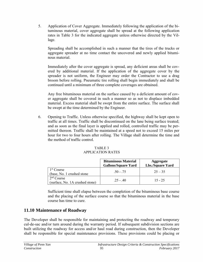
Village of Penn Yan Infrastructure Design Criteria & Construction Specifications
Construction 95 February 2017
5. Application of Cover Aggregate. Immediately following the application of the bi-tuminous material, cover aggregate shall be spread at the following application rates in Table 3 for the indicated aggregate unless otherwise directed by the Vil-lage.
Spreading shall be accomplished in such a manner that the tires of the trucks or aggregate spreader at no time contact the uncovered and newly applied bitumi-nous material.
Immediately after the cover aggregate is spread, any deficient areas shall be cov-ered by additional material. If the application of the aggregate cover by the spreader is not uniform, the Engineer may order the Contractor to use a drag broom before rolling. Pneumatic tire rolling shall begin immediately and shall be continued until a minimum of three complete coverages are obtained.
Any free bituminous material on the surface caused by a deficient amount of cov-er aggregate shall be covered in such a manner so as not to displace imbedded material. Excess material shall be swept from the entire surface. The surface shall be swept at the time determined by the Engineer.
6. Opening to Traffic. Unless otherwise specified, the highway shall be kept open to
traffic at all times. Traffic shall be discontinued on the lane being surface treated; and as soon as the final layer is applied and rolled, controlled traffic may be per-mitted thereon. Traffic shall be maintained at a speed not to exceed 15 miles per hour for two to four hours after rolling. The Village shall determine the time and the method of traffic control.
TABLE 3 APPLICATION RATES
Bituminous Material
Gallons/Square Yard
Aggregate
Lbs./Square Yard
1st Course (base, No. 1 crushed stone .50 - .75 25 – 35
2nd Course (surface, No. 1A crushed stone) .25 - .40 15 - 25
Sufficient time shall elapse between the completion of the bituminous base course and the placing of the surface course so that the bituminous material in the base course has time to cure.
11.10 Maintenance of Roadway The Developer shall be responsible for maintaining and protecting the roadway and temporary cul-de-sac and/or turn around during the warranty period. If subsequent subdivision sections are built utilizing the roadway for access and/or haul road during construction, then the Developer shall be responsible for special maintenance provisions. These provisions could be placing or
Village of Penn Yan Infrastructure Design Criteria & Construction Specifications
Construction 96 February 2017
replacing topping, periodic cleaning and flushing of the road surface and repair of any structural damage. The Developer shall submit a schedule of his proposed "road maintenance program" to the Village indicating how the roadway will be maintained, a timetable for the proposed mainte-nance and an estimate of cost. This schedule shall be reviewed and approved by the Village and shall become part of the project work. The approved estimated amount for maintenance shall be included in the letter of credit. 11.11 Temporary Turnarounds In areas where a temporary turnaround is proposed, the applicant shall provide sufficient details on the plan showing the road section, dimensions of the roadway and the materials proposed. The turnaround shall comply with materials shown on the "Typical Road Section", except as-phalt top course may be omitted. Developer shall provide cost in the letter of credit to cover the cost of the proposed temporary construction.
The turnaround shall be built to accommodate the largest Village Highway Department Plow Truck and/or the largest Fire Truck operated by the Village Fire Department or by a Mutual Aid Fire Department. 11.12 Private Drives
A. Other Than Single Family Driveways
1. The minimum width of the traveled way for a single lot is to be 11'. Maximum percent of grade 10%.
2. The minimum width of the traveled way for two, three or four lots is to be 22'.
3. Drive subgrade (native earth beneath road base) to be shaped to a crown and compacted, to prevent ground water from becoming trapped in the road base.
4. Drive base to consist of a minimum of 9" of crushed stone meeting NYSDOT Item 304.15 and thoroughly compacted.
5. Drive-side swales are to be provided. Swale inverts to be at least 10" lower than road subgrade. Swales are to be graded to a minimum slope of 1% to provide pos-itive drainage to the nearest watercourse. Swale side slopes to be graded to at least 1 vertical to 3 horizontal slope and seeded to provide a healthy growth of grass.
6. If required by the Code/Zoning Officer, upon completion of private drive con-struction, the Developer's engineer shall submit written certification that the road was constructed in accordance with the approved plans and to the specifications of the Village of Penn Yan.
7. See private drive detail drawing at rear of book.
Village of Penn Yan Infrastructure Design Criteria & Construction Specifications
Construction 97 February 2017
8. Private drives and single family driveways in excess of 500' shall be provided with a permanent turn around for emergency vehicles.
11.13 Single Family Driveways See Driveway Entrance Section Detail at end of book.

Village of Penn Yan Infrastructure Design Criteria & Construction Specifications
Construction 98 February 2017
THIS PAGE INTENTIONALLY BLANK
Village of Penn Yan Infrastructure Design Criteria & Construction Specifications
Construction 99 February 2017
Section 12 Storm Drainage
12.1 Catch Basin Construction
A. Work
The Developer shall build catch basins as shown on the "Catch Basin Detail" and accord-ing to the following specifications.
B. Material
Galvanized reticuline frame and grate fabricated as indicated on NYSDOT standard sheet 655-04 or as manufactured by Borden Metal Products or equivalent. Galvanized reticu-line frame and grade sizes shall be as follows: NYSDOT #1 – 23-15/16" x 27-1/2" frame – 22-11/16" x 26-1/2" grate: To be used under normal conditions unless otherwise specified. To be used on a catch basin built with in-side dimensions of 18" x 24". NYSDOT #9 – 28-15/16" x 27-1/2" frame – 27-11/16" x 26-1/2" grate: To be used where specified under special conditions and in lawn area where required. To be used on catch basins built with inside dimensions of 24" x 24". Precast concrete catch basins may be used at contractor's option. The catch basin shall, as a minimum, be constructed at 3,500 psi air entrained concrete, 5" reinforced walls, 6" re-inforced base. All catch basins shall include a 4" drain pipe on three sides as shown on the standard detail.
C. Method
The catch basin shall be built on a foundation of 3,500 psi concrete. Three (3) 4-inch diameter perforated PVC pipe shall be placed to provide "weep drain-age". (See catch basin detail.) The blocks shall be built to a height to allow for 8" of concrete cap between the last row of blocks and the bottom of frame and grate as part of the concrete apron. Before pouring the concrete apron, the frame shall be adjusted on catch basin wall to al-low a l-l/2" drop from invert of gutter to top of grate (except under special conditions). This drop shall be formed gradually in the invert. The catch basin shall be provided with #1 and #2 crushed stone around the exterior, ex-tending from the bottom of the catch basin to the top of the masonry wall on a 2-on-l slope. This stone shall be compacted before pouring of the concrete apron.
Village of Penn Yan Infrastructure Design Criteria & Construction Specifications
Construction 100 February 2017
The inside of the catch basin shall be painted with one (1) coat of Koppers bitumastic 300M or approved equal. The lateral pipe leading from the catch basin to the storm man-hole shall be encased in #1 and #2 crushed stone and extending to the top of the trench. This pipe shall be smooth interior corrugated polyethylene pipe.
12.2 Construction of Storm Drains
A. Storm Water Sewer Pipe
Storm water sewer pipe shall be built of smooth interior corrugated polyethylene pipe.
The pipe shall be selected as to proper strength classification by the Developer's licensed professional engineer and shall be stated on the plans. Height of cover, nature of founda-tion soil, type of bedding and trench width shall be considered in specifying the pipe.
Developer shall be responsible for providing extra strength bedding, cradle or encasement if the design conditions cannot be met in the field. Whenever the storm sewer is under the road, the Village requires that the Developer's engineer specify the correct class for H-20 loading at the sewer depth.
B. Special Construction
Other types of sewer pipe may be used to meet unusual construction conditions when ap-proved by the Village Engineer. Concrete encasement or cradle for the sewer may be required where excessive loads are expected, particularly in shallow trenches or where subsoil conditions are unsatisfactory.
C. Manholes and Catch Basins
The materials used in the construction of manholes and catch basins shall conform to the details as shown on the Standard Details included hereinafter. Connecting pipe between catch basins shall be a minimum 8" diameter and from catch basin to sewer manhole shall be a minimum 12" diameter.
D. Special Structures
Detailed plans for the construction of storm sewer pump stations, box culverts, head-walls, bridges, erosion control structures, any necessary special manholes or catch basins, etc. shall be submitted to the Village Engineer for his approval prior to construction.
E. Handling Pipe
All pipes and fittings shall be handled carefully. Pipes and fittings shall not be dumped or dropped while unloading or during emplacement in the trench.
Village of Penn Yan Infrastructure Design Criteria & Construction Specifications
Construction 101 February 2017
F. Stockpiling Pipe
The Developer shall take all necessary precaution to insure the stability of any stockpile or individual length of pipe that is stored. Pipe stored along a road or sidewalk shall be placed so that it does not create a safety hazard or impair the free flow of traffic.
G. Fitting and Cutting Pipe
The joint surfaces of all pipes and fittings shall be clean, and shall fit together to form a tight joint. When setting pipe the workmanship and tools used shall be such that the quality and strength of the pipe is not impaired.
H. Joints
PVC plastic drain pipe and fittings shall be joined as recommended by the pipe manufac-turer. Smooth interior corrugated polyethylene pipe joints shall meet the requirements of NYSDOT Section 706-12.
All joints shall provide a secure pipe connection.
I. Line and Grade
All pipe shall be laid true to line and grade with bells upstream and shall have a full, firm and even bearing. Boulders or other natural obstructions shall not be considered cause for varying from true line and grade.
J. Trenches
Any suitable excavation methods may be used but storm sewer trenches shall be confined to the smallest area practical for proper construction. Hand methods shall be employed where it is deemed necessary by the Village Engineer to preserve trees or protect existing structures. All necessary precautions shall be taken when blasting to confine flying stone or debris and to protect and prevent damage to adjacent structures. Where necessary, sheeting and/or bracing shall be used to provide support and stability to the trench walls. Unless otherwise directed, sheeting and bracing shall be removed as the trenches are backfilled.
K. Barricades
All open excavations shall be completely surrounded with barricades, fenced and illumi-nated at night.
L. Spoil
All spoil material to be removed from the site shall be noted on the plans and appropriate permits granted for its temporary off-site stockpiling or disposal. Excavated material un-suitable for backfill or topsoil shall be removed from the site of the work as it is

Village of Penn Yan Infrastructure Design Criteria & Construction Specifications
Construction 102 February 2017
excavated. Excavated material that is to be used for backfill shall be placed in spoil banks located on only one side of the trenches or pits and at least two (2) feet away from the ex-cavation wall. These spoil banks shall be located where they will not interfere with the work, or contribute an overload to the wall of the excavation. Where necessary, the ex-cess material shall be removed to some other place and brought back when required.
M. Drainage
Necessary precautions shall be taken at all times to prevent the flooding of adjacent prop-erty. Drainage ditches, necessary relocation of stream channels, or other positive means of diverting and/or controlling the water shall be employed. No water shall be drained in-to a pipe or trench under construction. Water shall not be allowed to accumulate in the trenches but shall be drained or pumped away from the work to established drainage channels.
N. Pipe Installation
The pipe shall be set carefully to line and grade. At the contractor's option an industrial laser specifically made for pipe laying operations may be used to establish line and grade. The contractor shall closely follow all manufacturers’ recommendations with regard to maintaining accuracy.
O. Earth Foundation
Where pipe is installed on native earth the trench bottom shall be bedded as specified un-der Section 11.2 “P.” and “Q.” Low areas shall be filled with suitable crushed stone. Where rock in either ledge or boulder formation is encountered, it shall be removed be-low grade and replaced with suitable sand or crushed stone as shown on the construction details. Where a firm foundation is not encountered at the grade established due to soft, spongy or other unstable soil, (unless other special construction methods are called for on the plans) all such unstable soil, under the pipe and for a width of at least one diameter on each side of the pipe, shall be removed and replaced with suitable crushed stone or other approved suitable material properly compacted to provide adequate support for the pipe line.
P. Bedding - Hand Backfilling
Storm sewer shall be constructed using stone bedding as specified and shown on the de-tailed drawings. Additional earth shall be added and tamped alongside the pipe until the top of the pipe is reached. Both the pipe tamp and flat-bottomed tamp shall be used for this operation. When the top of the pipe is reached, an additional 9"-12" of earth shall be placed over the pipe by hand. The material shall be free of stones or rocks. The hand backfill shall follow closely behind pipe laying to prevent damage to or movement of the pipe by cave-in of the trench walls.
Village of Penn Yan Infrastructure Design Criteria & Construction Specifications
Construction 103 February 2017
Q. Backfill
Following the hand operation, backfill may be machine placed providing extreme care is used. Backfill shall be made to existing grade and left in a neat and uniform condition. Excess earth shall be windrowed over the trench area. Where the trench passes under a ditch, stream, swale, or drainage way, the backfill shall be left in such a manner as to al-low proper drainage as well as duplicate conditions as they existed prior to construction. The surface must be entirely free of lumps of earth, stones and debris. Adjacent roadways shall be swept clean of all rubbish and flushed with water if necessary. Shoulders of highways which have been cut shall be carefully shaped and consolidated by tamping or rolling.
R. Cradle
Where called for on the plans or as ordered by the Village to meet field conditions, pipe shall be installed on cradles. The Village will determine at the time of construction whether a dry or plastic mix will be used at any particular location depending upon trench conditions. The cradle shall be constructed of l:2-l/2:5 concrete, with commercial type l Portland Cement and clean, hard aggregate. Cradle material shall be placed to the width shown on the plans, or as ordered by the Village, and to an elevation l/4 up the side of the pipe. The pipe shall be laid in a channel formed in the material by means of a round-pointed shovel. High points and low spots shall be corrected and the pipe firmly bedded to line and grade and jointed. Additional cradle material shall then be added and tamped along the haunches of the pipe and subsequently shaped to the top of the pipe as shown on the Detail. "Safety cover" of 9"-12" of earth shall then be placed and backfill made as required under Section 11.2 “Q”.
S. Protection of Existing Sewers
Care shall be taken at all times to avoid entrance of mud and water to existing sewers. When connecting to an existing manhole, the connection shall be tightly plugged until completion of the work. At that time, the plug shall be removed and the accumulated wa-ter and mud pumped out of the manhole under the supervision of the Village. The cost of any necessary cleaning or flushing of existing facilities caused by failure to comply with this specification or for other reasons will be borne by the Developer.
T. Protection of New Work
At the end of each working day (or any other time of work stoppage), the upstream end of the pipe shall be tightly plugged to prevent entrance of mud, silt, or muddy water.
U. Construction Under Adverse Conditions
No pipe shall be laid during adverse weather conditions. In no case shall pipe be laid in water. In cases where storm sewers are being installed in wet conditions or below the groundwater table so that installed pipes become submerged overnight, sufficient back fill shall be placed to prevent the pipe becoming buoyant.
Village of Penn Yan Infrastructure Design Criteria & Construction Specifications
Construction 104 February 2017
V. Conflicting Pipe Lines & Other Utilities
No existing pipe line, conduit, cable, pole, guy wire or other utilities or portion thereof shall be moved without the consent of the Agency operating such utility. Any necessary changes in line and grade of the new pipe line shall be made only with the consent of the Village.
W. House Laterals
House laterals may extend to the R.O.W. line and shall daylight to allow for overland flow prior to entering the storm sewer for each lot. These laterals shall be constructed with the same care as street sewers. The storm water laterals shall be 6-inch diameter and shall be installed on a minimum slope of l/8" per foot. Laterals shall be firmly bedded in #1 or a blend of #1 and #2 crushed stone bedding meeting the requirements of NYSDOT Section 703-02. They shall be laid true to line and grade, and the bedding material shall be tamped under the pipe and alongside the haunches to provide full bedding and lateral support for the entire length of the pipe. The interior of each pipe shall be cleaned before adding the next length of pipe. Laterals shall be installed at depths not greater than 10'.
A record shall be kept of the location of all laterals and this information shall be shown on the Record Plans.
Storm Sewer Lateral Material
Pipe shall be 6-inch diameter and one of the following:
1. Poly Vinyl Chloride (PVC) Pipe SDR-35 with push on neoprene gaskets ASTM D-2241.
2. Smooth interior corrugated polyethylene pipe.
Village of Penn Yan Infrastructure Design Criteria & Construction Specifications
Construction 105 February 2017
Section 13 Sanitary Sewer Facilities
13.1 Gravity Sewer
A. Pipe Installation
1. Standards
a. Installation specifications shall contain appropriate requirements based on the criteria, standards, and requirements established by industry in its tech-nical publications. Requirements shall be set forth in the specifications for the pipe and methods of bedding and backfilling thereof so as not to damage the pipe or its joints, impede cleaning operations and future tapping, nor create excessive side fill pressures and ovalation of the pipe, nor seriously impair flow capacity.
2. Preparation
a. The alignment and subgrade of all trenches and excavations shall be deter-mined from survey bench marks and overhead grade lines or laser beam method at the Developer's option. The Developer shall check and be re-sponsible for the survey control data before making use of it. The Developer shall preserve all benchmarks and maintain a complete and accurate record of the final sewer and structure locations with respect to the survey control data. The Developer shall set the sewer grade line which shall be main-tained throughout.
3. Trenching
a. The width of the trench shall be ample to allow the pipe to be laid and joint-ed properly and to allow the bedding and haunching to be placed and compacted to adequately support the pipe. The trench sides shall be kept as nearly vertical as possible. When wider trenches are specified, appropriate bedding class and pipe strength shall be used.
b. In unsupported, unstable soil, the size and stiffness of the pipe, stiffness of the embedment and insitu soil and depth of cover shall be considered in de-termining the minimum trench width necessary to adequately support the pipe.
c. Ledge rock, boulders, and large stones shall be removed to provide a mini-mum clearance of 6 inches below and on each side of all pipe(s).
d. The work shall be performed by acceptable construction. Excess excavated earthen materials shall be stockpiled on-site in a manner and location ac-ceptable to the Village. Material such as excavated asphalt shall be disposed of off-site in conformance with applicable legal requirements. Disposal sites
Village of Penn Yan Infrastructure Design Criteria & Construction Specifications
Construction 106 February 2017
must be approved by the Village and NYSDEC. Materials for reuse on the project shall be stockpiled in an approved designated area adjacent to the work site.
e. Provide adequate temporary crossovers for pedestrian and vehicular traffic, including temporary gravel drives, guard rails, lamps, and flags; remove same when necessity for such protection ceases.
f. Protect trees indicated to remain in place by means of wrapping, banding, guys, or other methods, as required.
g. Pipe trenching, building foundations, and structural undercuts: under nor-mal conditions, the excavation shall be vertical open cut from the ground surface. Tunneling beneath trees and certain surface structures may be re-quired.
h. Bottom of excavations shall be finish graded by hand methods to receive bedding. The stone bedding shall be placed, compacted, and trimmed by hand to ensure the grade as necessary or as detailed.
4. Methods of Control for Excavations and Grading
a. The Developer shall be responsible for the proper layout of utilities, struc-tures, and drainage. He shall maintain adequate stakeout control for inspection of the work and to accurately complete construction.
b. The alignment and depth of subgrades of all pipe trenches shall be deter-mined by overhead grade lines or laser at Developer's option, installed and maintained by his surveyor.
5. Limit of Excavation for Pipelines
a. Trenches shall be excavated as shown on the Standard Details.
6. Limit of Excavation for Structures
a. Excavations for structures and facilities shall be of sufficient size to give suitable room for proper construction procedures and no larger.
7. Limit of Excavation for Removal or Abandonment of Materials
a. Excavations for the removal of any materials shall be of sufficient size to properly complete the work and no larger.
8. Excavations Below Subgrade
a. Whenever excavations are carried beyond or below the lines and grade shown, all such over excavation shall be backfilled with special backfill

Village of Penn Yan Infrastructure Design Criteria & Construction Specifications
Construction 107 February 2017
(Type B) Crushed Stone (#1 and #2) 50-50 mix, concrete or other materials as directed by the Village.
b. In case earth materials encountered at subgrades are not suitable, the Devel-oper shall immediately notify the Village and shall excavate from the limiting subgrades shown or specified, to such new lines and grades, as will be ordered. Excavation below subgrade shall be done only upon express or-ders of the Village.
c. All material which slides, fails, or caves into the established limits of exca-vations due to any cause whatsoever, shall be removed and disposed of by the Developer. It is the Developer's responsibility to make all excavations safe for ongoing construction.
B. Backfill
1. Natural Materials Defined
a. Common Earth - shall mean sand, loam, clay, gravel, or similar materials free from debris, frozen materials, organic materials, or other deleterious material, and containing some rock fragments, stones, and pebbles, not ex-ceeding 12 inches in their largest dimension and site excavated material approved by the District.
b. Select Earth - shall mean sand, silt, select granular material and similar ma-terial free of clay, loam, organic material, debris, frozen material or other deleterious material and stone with any linear dimension greater than three (3) inches.
c. Topsoil - shall be the surface layer of soil with no admixtures or material toxic to plant growth. Care should be taken to limit the amounts of subsoil refuse, roots, branches, and other debris mixed with the topsoil during strip-ping and stockpiling.
1) Imported topsoil shall meet the following requirements:
a) The pH of the material shall be between 5.5 and 7.6.
b) The organic content shall be not less than 2% or more than
20%.
Village of Penn Yan Infrastructure Design Criteria & Construction Specifications
Construction 108 February 2017
c) Gradation Sieve Size % Passing By Weight 2" 100% 1" 85 - 100% 1/4" 65 - 90% #200 20 - 80%
The Developer shall be responsible for amending imported topsoil with approved materials and by approved methods to meet the above specifications, at no additional cost to the District. The material shall be stockpiled and tested prior to use on the project.
d. Rock - shall comprise solid rock in the original bed or in well-defined ledg-
es, and which can only be removed by continuous blasting and/or jack hammering. It shall include boulders or detached pieces of rock two cubic yards or greater in size.
e. Loam - shall be defined as a soil mixture consisting of the following propor-tions:
Sand 30 - 50% Silt 30 - 50% Clay 0 - 20%
2. Granular Items Defined
The various types of backfill material specified below shall be used, where speci-fied on the drawings.
a. Type A - Material shall be clean and sound and shall be either: gravel,
screened gravel or crushed stone. It shall consist of 100% by weight passing a 1-1/2 inch square opening, not more than 90% by weight passing an inch square opening and not more than 10% by weight passing 1/4" square open-ing.
b. Type B - Material shall be clean, sound, crushed stone of uniform quality. It shall be a 50-50 mixture of NYSDOT size designation #1 and #2 stone as per NYSDOT Standard Specifications Section 703-02 latest revision.
c. Type C - Material shall be clean, sound, crushed stone of uniform quality. It shall meet the gradation of #1 stone as per NYSDOT Standard Specifica-tions Section 703-02 latest revision.

Village of Penn Yan Infrastructure Design Criteria & Construction Specifications
Construction 109 February 2017
d. Type D - Material shall consist of washed coarse sand having the following gradation by weight.
% Passing Sieve 100 3/8 inch 90-100 No. 4 80-100 No. 8 50-85 No. 16 25-60 No. 30 10-30 No. 50 2-10 No. 100
e. Type E - Material shall meet the requirements of Item 304.05 as defined in the NYSDOT Standard Specifications latest revision.
f. Type F - Material shall meet the requirements of Item 304.04 as defined in the NYSDOT Standard Specifications latest revision.
g. Type I - Material shall meet the requirements for select granular fill Item 203.07 as defined in the NYSDOT Standard Specifications latest revision.
h. Type J - Material shall be a clean, sound, screened stone (Pea-Stone) of uni-form quality. It shall meet the gradation of #1A stone as per NYSDOT Standard Specifications Section 703-02 latest revision.
i. Type K - Material shall be a clean, sound, washed gravel of uniform quali-ty. It shall consist of 100% by weight passing a 1-1/2 inch square opening, 90-100% by weight passing a 1 inch square opening and not more than 5% by weight passing a 1/2 inch opening.
j. Type L - Granular undercut backfill material shall meet the following gra-dation:
% Passing Sieve 90-100% 3 inch 40-70% 1/4 inch 15-30% # 40 10-25% #100 0-20% #200
3. General Requirements
a. All excavations shall be backfilled to the original surface of the ground or to such other grades as may be shown, specified, or directed. Backfilling shall

Village of Penn Yan Infrastructure Design Criteria & Construction Specifications
Construction 110 February 2017
be done with suitable excavated materials as shown on the Standard Details and satisfactorily compacted.
b. Undercut backfill shall meet the gradation specified under Type L granular material and shall be placed in lifts not to exceed 12 inches in depth.
c. Excavated material considered by the Village to be unsuitable for backfill-ing shall not be used, and shall be stockpiled or removed from the site according to the following:
1) Unsuitable material shall fall into two specific categories. The first shall be that material which would be unsuitable under any circum-stances. Material containing humus, spongy material, roots, stumps, muck, peat, and any other objectionable material. This material shall be disposed of in an approved spoil area.
2) The second category shall consist of material that which is unsatisfac-
tory for backfill because of its moisture content at the time of excavation. This material shall be stockpiled in approved areas on the Project site. This stockpiled material, when satisfactory for backfill, shall be used in other areas lacking backfill or appropriately disposed of.
d. The Village shall be the sole judge of what constitutes unsuitable material
and into which category it falls. Any deficiency in backfill shall be made up in spoil, if suitable, or by acceptable imported material.
e. When it is necessary to haul material over the streets or pavements, the De-veloper shall provide suitable tight vehicles so as to prevent deposits on the streets or pavements. In all cases where any materials are dropped from the vehicles, the Developer shall clean up the same as often as directed and keep the crosswalks, streets, and pavements clean and free from dirt, mud, stone, and other hauled material.
f. As required the Developer may add sufficient water during compaction to assure a complete consolidation of the material.
g. The Developer shall make up any settlement of trenches or embankments with suitable material and stabilize.
4. Backfilling of Trenches
a. All pipes shall be protected from lateral displacement and possible damage resulting from backfill operations through, impact or unbalanced loading, by maintaining the pipe adequately embedded. Except where detailed or due to subsoil conditions that require the use of concrete cradle encasement, all pipe embedment shall be placed so as to insure adequate lateral and vertical stability of the installed pipe during pipe jointing and backfill operations. A
Village of Penn Yan Infrastructure Design Criteria & Construction Specifications
Construction 111 February 2017
sufficient amount of the specified pipe backfill material to hold the pipe in rigid alignment shall be uniformly deposited and thoroughly compacted be-low, on each side, as well as above each pipe laid in accordance with the limits as shown on the Standard Details.
b. Pipe backfill materials placed any point below an elevation of 12 inches above the top of the pipe barrel shall be placed and compacted in layers not to exceed 6 inches in uncompacted depth and shall be done simultaneously and uniformly on both sides of the pipe to the limits as shown on the Stand-ard Details. All such materials shall be graded in the trench with hand tools in such a manner that they will be placed uniformly alongside the pipe. The remainder of the trench shall be backfilled with material as shown on the standard details. In grassed areas, this remaining backfill shall be suitable excavated material and shall not exceed 12-inch lifts after compaction. When placed under pavement, utilities, and other structures this remaining backfill shall be select granular material. Each layer shall be thoroughly compacted to prevent settlement.
c. Where trenches are constructed in, near, or across roadway ditches or other water courses, the backfill shall be protected from surface erosion.
d. Trucks or other heavy equipment shall not be operated over pipelines until a minimum of 24 inches of backfill above the crown of the pipe has been placed and properly compacted.
5. Backfilling Around Structures
Prior to backfilling, a minimum of seven (7) days cure time shall elapse from the placing of cast-in-place concrete. In no case shall backfill materials be allowed to fall directly on a structure or to damage the structure or its protective coatings. Backfill around structures shall be deposited in horizontal layers not more than 9 inches in thickness and shall be compacted by tamping to prevent settlement. Backfill shall be brought up evenly on all sides of structures so as not to subject the structure to unequal loadings.
6. Stone Backfill
a. Place stone fill in a manner so as to produce a reasonably well graded sec-tion. The placed stone surface shall be chinked with smaller stones to form a uniformly filled condition.
b. Placing stones in layers or dumping by methods likely to cause segregation of the various sizes is not permitted. Obtain the desired distribution of the various sized stones by selectively loading, controlled dumping of succes-sive loads or by other approved mechanical means.
Village of Penn Yan Infrastructure Design Criteria & Construction Specifications
Construction 112 February 2017
c. Completely fill voids with fine stone. Rearranged stones by mechanical equipment or by hand to the extent necessary to obtain a reasonably well grade distribution.
7. Preparation of Pavement Subgrades
a. Prior to placement of fill, the embankment foundation shall be thoroughly inspected by the Village. If in the opinion of the Village, the embankment foundation is not adequate to support pavement the embankment foundation shall be proof-rolled by a roller or loaded ten wheeler to the satisfaction of the Village. Any loose, soft, wet, frozen, organic, or otherwise unsuitable material shall be removed.
b. Shape the entire subgrade to the required line, grade, and cross slope. Re-move any protruding stones larger in diameter than 5 inches and fill the resulting depressions with an approved material.
c. Roll the subgrade surface with a roller weighing not less than 10 tons and achieve the required compaction densities specified. If during construction, the Developer allows the subgrade to become wet and rutted, re-shape, aer-ate, recompact subgrade, as required. Compact the entire width of the area to receive pavement and shoulders. Where subgrade failures occur due to rolling, thoroughly roll and compact these areas until no further consolida-tion is apparent.
d. When pavements cannot be placed immediately after the preparation of the subgrade, the entire, subgrade area shall be restricted to construction traffic until subbase materials can be placed.
e. After rolling, the finished subgrade shall not vary more than 0.05 feet from the established grade and cross slope.
f. Do not disturb the finished subgrade by traffic or other operations and pro-tect and maintain in a satisfactory condition until the overlaying granular materials are placed.
8. Shoring
a. Steel Sheet Piling
1) Steel sheeting shall be of the continuous interlocking type. Rolled corners and structural materials shall be of structural grade steel.
2) Steel sheeting shall be sound and shall conform with ASTM A328,
with a minimum thickness of 3/8 inch. The Developer shall submit design plans for steel sheeting installation for the Village to review prior to use. The design plans shall be stamped by a professional en-gineer licensed to practice in New York State and shall be designed in
Village of Penn Yan Infrastructure Design Criteria & Construction Specifications
Construction 113 February 2017
conformance with the current requirements of OSHA Safety and Health Standards (29 CFR 1926) and latest revisions.
b. Timber and Lumber for Sheeting
1) Timber and lumber includes all dimensions and structural grades used for shoring, sheeting, and bracing. It shall be of the grade, species and dimensions required, shown or specified.
2) All timber and lumber shall be hardwood free from shakes, wanes,
unsound knots and decay and shall be smoothed and squared through-out its length. Structural grade lumber shall meet the requirements of ASTM DES: D-245. Stress grade lumber and fastenings shall also conform to the "Natural Design Specifications for Stress Grade Lum-ber and Its Fastenings." All lumber shall be new, unless the use of second-hand lumber is specifically approved prior to its use by the Village. All timber sheeting and bracing shall conform to National Design Specifications for Stress Grade Lumber of a minimum fiber stress of 1200 lbs. per square inch.
3) All timber sheeting design shall be stamped by a professional engi-
neer licensed to practice in New York State. All sheeting shall be designed in conformance with the current requirements of OSHA Safety and Health Standards (29 CFR 1926) and latest revisions.
c. General Installation Requirements
1) The Developer shall furnish, place, and maintain sheeting, bracing and shoring as may be required to support excavation walls and pre-vent any earth movement which could damage pipe or to avoid delay of the work, to reduce the width of excavation required, or to maintain a safe and adequate working condition. The Developer shall furnish and install timber or steel sheeting in locations as required. Such sheeting shall include anchorage structures and connecting materials and all necessary appurtenances, whalers, deadman anchors, walling strips, and caps to provide a complete job.
2) The Developer shall be responsible for the adequacy of all sheeting
and bracing used and for all damage to persons or property resulting from improper quality, strength, placing, maintenance and removal.
3) All sheeting and bracing shall be furnished and installed by the De-
veloper in accordance with the minimum standards set forth by the Occupational and Safety and Health Administration (OSHA). All sheeting shall be adequate and conform to current requirements of OSHA (29 CFR 1926) and latest revisions.
Village of Penn Yan Infrastructure Design Criteria & Construction Specifications
Construction 114 February 2017
4) The Developer shall submit details of the timber or steel sheeting pro-posed for use for the information of the Village.
5) At the Developer's option, a "safety shoring shield" may be used in-
stead of temporary sheeting and bracing. The height and length of shield are determined by trench conditions.
6) All excavations within ten (10) feet of any utility line shall be braced
or sheeted if the invert of the pipe being installed is more than five (5) feet below that of the existing utility line. It shall be the responsibility of the Developer to prevent damage to or displacement of utilities.
7) If, in the judgment of the Village, the sheeting or supports furnished
are inadequate or unsuited for the purpose, the Village may order such sheeting or bracing to be replaced or additional sheeting and bracing to be installed. Detailed sheeting designs stamped by a NYS Profes-sional Engineer may be required to be submitted by the Developer to determine the adequacy of submitted shoring plans. Any design costs and resulting installations of sheeting and bracing ordered and so in-stalled for such purpose shall be furnished and installed at the expense of the Developer.
8) Whether or not the Village orders any additional sheeting or bracing
to be installed or unsuitable sheeting or bracing to be replaced, the Developer shall be solely responsible for adequacy of all sheeting and bracing.
9. Compaction
a. Utilize the proper compaction methods and equipment to suit the soils and conditions encountered.
10. Laboratory Test Reports
a. As a minimum, the laboratory maximum density testing reports shall con-tain the following:
1) Laboratory's name. 2) Date, time, and specific location from which sample was taken and
name of person who collected the sample. 3) Moisture - Density Curve plotted on graph paper to as large a scale as
is practical with all points used to derive the curve being clearly visi-ble.
4) Designation of the test method used. 5) The optimum density and moisture content. 6) A description of the sample.
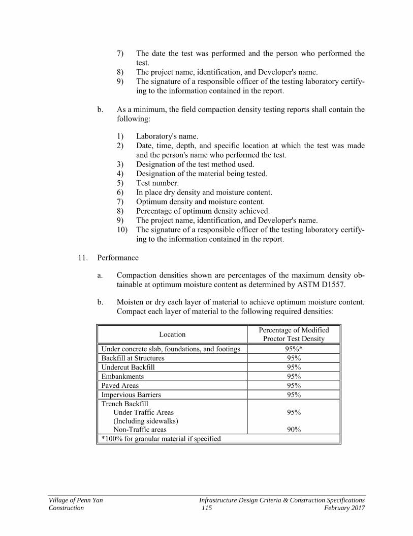
Village of Penn Yan Infrastructure Design Criteria & Construction Specifications
Construction 115 February 2017
7) The date the test was performed and the person who performed the test.
8) The project name, identification, and Developer's name. 9) The signature of a responsible officer of the testing laboratory certify-
ing to the information contained in the report.
b. As a minimum, the field compaction density testing reports shall contain the following:
1) Laboratory's name. 2) Date, time, depth, and specific location at which the test was made
and the person's name who performed the test. 3) Designation of the test method used. 4) Designation of the material being tested. 5) Test number. 6) In place dry density and moisture content. 7) Optimum density and moisture content. 8) Percentage of optimum density achieved. 9) The project name, identification, and Developer's name. 10) The signature of a responsible officer of the testing laboratory certify-
ing to the information contained in the report.
11. Performance
a. Compaction densities shown are percentages of the maximum density ob-tainable at optimum moisture content as determined by ASTM D1557.
b. Moisten or dry each layer of material to achieve optimum moisture content. Compact each layer of material to the following required densities:
Location Percentage of Modified Proctor Test Density
Under concrete slab, foundations, and footings 95%* Backfill at Structures 95% Undercut Backfill 95% Embankments 95% Paved Areas 95% Impervious Barriers 95% Trench Backfill Under Traffic Areas (Including sidewalks) Non-Traffic areas
95%
90%
*100% for granular material if specified
Village of Penn Yan Infrastructure Design Criteria & Construction Specifications
Construction 116 February 2017
12. Field Quality Control
a. The testing laboratory shall perform a laboratory maximum density test for each type of soil proposed for use or encountered in the work. Determine optimum moisture content in accordance with ASTM D1557.
b. The Village will designate the time, date, and exact location of all field compaction density tests. Field density tests may be ordered by the Village at their discretion in accordance with the following average frequencies:
c. Under Structures, Foundations, Slabs, and Footings: One test for every 100 square foot area of each lift of compacted fill or backfill.
d. Trenches: One test for each foot of backfill at intervals of approximately 200' along each trench.
13. Field density and moisture testing shall conform to the requirements of ASTM D1556 (sand cone) or D2922 and ASTM D3017 (nuclear density). Soils shall be described in accordance with ASTM D2488, Visual-Manual Procedure.
C. Installation of Ductile Iron, and PVC Pipe - General
1. All sanitary sewers shall be laid in an embedment of granular material. The select backfill material shall be thoroughly compacted by hand and extend a minimum of 6" above the top of the pipe.
2. Pipe subgrade preparation shall be performed immediately prior to installing the pipe in the trench. All trench bottoms shall be graded to provide uniform and con-tinuous bearing and support on solid and undisturbed ground for the entire length of pipe.
3. Each bell hole shall be excavated immediately prior to laying the pipe so that no part of the pipe bell or coupling will be in contact with the trench bottom or gran-ular fill thereon.
4. All trenches shall be so graded that the spigot end of the pipe will be accurately centered in the adjacent pipe bell when laid, without raising the pipe off the trench bottom. Regrading of the trench bottom which is too high will be permitted. Cor-rection of a subgrade that is too low shall be done only by placing and compacting approved granular bedding material over the entire width of the trench and regrad-ing.
5. Pipe shall be laid from the downstream end. All pipes shall be laid to the line and grade shown on the plan unless otherwise directed.
6. No pipe shall be laid in water or when weather and trench conditions are unsuita-ble for pipe laying.
Village of Penn Yan Infrastructure Design Criteria & Construction Specifications
Construction 117 February 2017
7. Before lowering and while suspended, the pipe shall be inspected for defects. Any defective, damaged, or unsound pipe shall be rejected. All foreign matter such as dirt shall be removed from the inside of the pipe before it is lowered to this posi-tion in the trench. The pipe and accessories shall be kept clean during and after laying. The open ends of pipelines shall be closed by test plugs or other suitable means at all times when pipe laying is not in progress. Pipeline materials shall be carefully handled and not dropped or dumped.
8. The cutting of pipe for inserting fittings or closure places shall be done in a neat and workmanlike manner without damage to the pipe or lining. In general, pipe shall be laid with bell ends facing in the direction of laying. Pipes shall be fur-nished in standard laying lengths. Random short lengths shall be used only as required to connect manholes. These short lengths for manholes shall not exceed 6'-0" in length.
9. Jointing shall be accomplished in strict accordance with manufacturer's recom-mendations. Lubricant used at the joint shall be water soluble, non-toxic, non-supporting of bacteria growth and have no deteriorating effects on the pipes or gaskets. Solvent for pipe jointing shall be as recommended by the manufacturer of the pipe.
10. Push-on joints shall be assembled in full accordance with the manufacturer's in-structions and the following procedures:
a. The inside of the bell and spigot ends of the pipe to be joined shall be cleaned and washed thoroughly with soapy water until free from sand, dirt, and foreign material.
b. The joint gasket shall be inserted in the bell with the groove over the head in the bell gasket seat.
c. A film of special lubricant shall be applied to the entire gasket face on the inside of the bell.
d. The spigot end of the joining pipe shall be set in the bell until the spigot touches the gasket.
e. The pipe shall be pushed or jacked into the bell only as far as the reference marks provided on the spigot indicate.
f. When necessary to cut push-on joint pipe in the field, the outside edge of the cut end shall be conditioned for use by filing or grinding a small taper at an angle of 30 degrees.
g. All defective push-on joints shall be re-assembled and the defective materi-al shall be discarded.

Village of Penn Yan Infrastructure Design Criteria & Construction Specifications
Construction 118 February 2017
D. Lateral Construction
1. Prefabricated wye connections to the main shall be utilized for laterals.
2. The Developer shall install the lateral in a trench that is perpendicular to the sew-er. The invert elevation of the lateral shall be set such that at the face of the house foundation, the invert is a minimum of 2 feet below the finished floor.
3. A cleanout shall be installed.
4. Wye connections and ends of laterals shall not be backfilled until a record has been made by the Developer of the "as-built" location of each.
5. All joints shall be installed, made up, and inspected in accordance with approved printed instructions of the manufacturer. Joint tolerances shall be specified in ASTM D3139 and F477 for polyvinyl chloride pipe.
6. The manufacturer shall test and furnish test certificates covering all pipe supplied under this contract conforming to the test requirements as specified in ASTM D2241 for polyvinyl chloride pipe.
7. All pipe shall be cut by approved power saws which will produce a clean, true cut, free from irregularities and a smooth end at right angles to the axis of the pipe. All cut ends shall be beveled. No other method of pipe cutting will be ac-cepted.
8. All pipes and fittings shall be handled carefully in loading and unloading. They shall be lifted by hoists and lowered on skidways in such a manner as to avoid shock. Derricks, ropes, or other suitable equipment shall be used for lowering the pipe into the trench. Pipe and fittings shall not be dropped or dumped.
9. Each pipe and fitting shall be inspected before it is lowered into the trench. The interior of the pipe and all joint surfaces shall be thoroughly cleaned and shall thereafter be maintained clean. Care shall be taken in applying soap to facilitate joining of pipe sections. Soap shall be used sparingly. All pipe shall be laid true to line and grade with bells upstream and shall have a full, firm, even bearing. No length of pipe shall be laid until the previous length has sufficient backfill materi-al placed and compacted about it to secure it firmly in place to prevent any disturbance. The open ends of pipe shall be securely plugged whenever pipe lay-ing is not in progress. Under no conditions shall pipe be laid in water, and no pipe shall be laid when trench or weather conditions are unsuitable for such work. Pipe and fittings shall be selected so that there will be as small a deviation as possible at the joints and so that inverts present a smooth service. Pipe and fittings, which do not fit together to form a tight joint, will be rejected.
10. Where an existing pipe or duct crosses the trench at an elevation which conflicts with the proposed grade for the new lateral, either the grade for the new lateral shall be changed or the existing pipe shall be relocated. The new lateral shall have
Village of Penn Yan Infrastructure Design Criteria & Construction Specifications
Construction 119 February 2017
a clearance from the existing pipe of not less than six (6) inches. The space be-tween the two (2) pipes shall be solidly filled with compacted sand. Before the trench is refilled, the existing pipelines shall be permanently supported as required by the Agency operating such pipelines.
11. Any section of the lateral that is found defective in material, alignment, grade, joints, or otherwise shall be satisfactorily corrected by the Developer.
12. The connecting fitting between new and existing laterals shall be a coupling con-forming to ASTM C425, using an elastomeric sleeve, corrosion-resistant shear collar and tension bands and tightening mechanism.
E. Construction of Sewers Crossing Streams
1. Materials
Sewers entering or crossing streams shall be constructed of high density polyeth-ylene (HDPE) with fused joints; otherwise they shall be constructed so they will remain watertight and free from changes in alignment or grade. Material used to backfill the trench shall be sand, washed gravel, or other materials which will not readily erode, cause siltation, damage pipe during placement, or corrode the pipe.
2. Siltation and Erosion
Construction methods that will minimize siltation and erosion shall be employed. The design engineer shall include in the project specifications the method(s) to be employed in the construction of sewers in or near streams. Such methods shall provide adequate control of siltation and erosion by limiting unnecessary excava-tion, disturbing or uprooting trees and vegetation, dumping of soil or debris, or pumping silt-laden water into the stream. Specifications shall require that cleanup, grading, seeding, and planting or restoration of all work areas shall begin immedi-ately. Exposed areas shall not remain unprotected for more than seven days.
F. Testing of Sanitary Sewers and Appurtenances
1. General
a. Upon completion of construction of the sanitary sewer, the Developer shall clean and flush all pipes. The system shall be left free of all stones, sand, silt, or mortar projections. The benches and inverts of manholes and bot-toms of inlets shall have all mortar dropping chipped away to leave a smooth, clean surface.
b. All materials flushed from the sanitary sewer shall be intercepted and re-moved to prevent the materials from entering the existing sanitary sewer system.
Village of Penn Yan Infrastructure Design Criteria & Construction Specifications
Construction 120 February 2017
c. The Developer shall supply all materials, equipment, and labor as required to test the gravity mains, manholes, and appurtenances in accordance with the provisions of these specifications.
d. The sanitary sewer shall be inspected and a video tape recording shall be created and this tape shall be given to the Village.
2. Test for Displacement of Gravity Sewers
a. Sewers shall be checked to determine whether any displacement of the pipe has occurred. The test will be as follows: The test shall be conducted after the final backfill has been in place at least 30 days. No pipe shall exceed a deflection of 5%. If the deflection tests are to be run using a riding ball or mandrel, it shall have a diameter equal to 95% of the inside diameter of the pipe. The test shall be performed without mechanical pulling devices.
3. Leakage and Leakage Tests
a. Upon completion of construction and backfilling of sewer appurtenances all pipelines shall be thoroughly flushed out with water and prior to ac-ceptance, the entire system, including manholes shall be inspected and tested. Test section shall be no greater than 300 feet in length.
b. The tests for watertightness shall be made by the Developer. The Developer shall furnish the necessary facilities for making the tests and determining groundwater conditions at the time of the test.
4. Hydrostatic-exfiltration and infiltration tests shall be conducted for a minimum test period of 24 hours.
a. Exfiltration (Gravity Sewer Lines)
1) Where no groundwater exists at the time of the tests, the sewers, manholes, and house connections shall be subjected to an internal wa-ter pressure test to the extent deemed necessary to determine their watertightness.
2) The lower end of the section shall be tightly plugged and the line
filled with water. The line shall be vented to allow the air to escape from the pipe and the water level shall be brought to a point two feet above the crown of the pipe at its upper end at a manhole. The two foot head of water at the upper end shall be maintained for at least one hour.
b. Infiltration (Gravity Sewer Lines)
1) Infiltration test shall be made in groundwater conditions as a check for watertightness of the sewers after backfilling has been completed

Village of Penn Yan Infrastructure Design Criteria & Construction Specifications
Construction 121 February 2017
and sufficient time has elapsed to permit the groundwater to rise to its normal level.
2) The test shall be made by using approved low head measuring weirs
placed at the lower ends of the sections to be tested or by other ap-proved methods. The Developer shall erect a temporary bulkhead to shut off flow from above the section being tested, and shall provide pumps downstream of the measuring device to keep the system drained for the period of the test.
c. Allowable Leakage (Gravity Sewer Lines)
1) The maximum allowable leakage in the sewer lines shall be 100 gal./mile/24 hours per one inch of internal diameter of the sewer.
2) Any section of sewer piping which does not meet the specified leak-
age test shall be repaired by the Developer.
3) Low Pressure Air Acceptance Test (Gravity Sewer Lines)
a) Air pressure tests shall be run following the guidelines of Uni-Bel (UNI-B-6-98) "Recommended Practice: For Low Pressure Air Testing of Installed Sewer Pipe".
b) All branch fittings and ends shall be securely plugged to with-stand the internal test pressures. The section of line being tested shall also be securely plugged at each manhole. All stoppers shall be adequately branched when required.
G. Video Taping Sanitary Sewer System
1. The camera shall be moved through the line in either direction at a moderate rate, stopping when necessary to permit proper documentation of the sewer's condition. In no case will the television camera be pulled at a speed greater than 30 feet per minute. Manual winches, power winches, TV cable, and powered rewinds or oth-er devices that do not obstruct the camera view or interfere with proper documentation of the sewer conditions shall be used to move the camera through the sewer line.
2. When manually operated winches are used to pull the television camera through the line, telephones or other suitable means of communication shall be set up be-tween the two manholes of the section being inspected to ensure good communications between members of the crew.
3. The importance of accurate distance measurements is emphasized. Measurement for location of defects shall be above ground by means of a meter device. Mark-ing on the cable, or the like, which would require interpolation for depth of manhole, will not be allowed. Accuracy of the distance meter shall be checked by
Village of Penn Yan Infrastructure Design Criteria & Construction Specifications
Construction 122 February 2017
use of a walking meter, roll-a-tape, or other suitable device, and the accuracy shall be satisfactory to the Village.
4. Documentation of the videotaping shall be as follows:
a. Television Inspection Logs: Printed location records shall be kept by the Developer and will clearly show the location in relation to an adjacent man-hole of each lateral wye and any problem point observed during inspection.
b. Videotape Recordings: The purpose of tape recording shall be to supply a visual and audio record of areas of the lines that may be replayed. Vide-otape recording playback shall be at the same speed that it was recorded. Slow motion or stop-motion playback features may be supplied at the op-tion of the Developer. Title to the tape shall remain with the Developer, however, the Developer shall provide to the Village a complete set of tapes and logs at the completion of the inspection.
13.2 Pressure Sewer Pipe Installation
A. General
1. Pipe and fittings shall be handled in such a manner that the coating and lining are not damaged during their delivery, storage, or installation. Pipe with damaged coatings or linings shall be repaired or replaced by the Developer.
2. All pipe shall be cut accurately to size and installed without forcing. Pipe shall be installed so that it can expand or contract without damage. Pipes shall be carefully fitted to the equipment and care shall be used not to force either the pipe or equipment into place. After the piping has been placed, the equipment shall be again checked for level and alignment.
3. Whenever valves or other equipment are located in or connected to a pipeline, the connections must be such that the valves or equipment can be removed without disturbing the rest of the pipeline.
4. Flanged pipes shall be fitted together using best quality cloth inserted rubber, full faced, minimum 1/8" thick gaskets, and bolts tightened evenly.
5. The trench shall be excavated to the required alignment and width, and to a depth that will assure a minimum cover of 4.5 feet over the top of the pipe after con-struction has been completed. The Developer shall dewater the trench and keep it free of water at all times.
6. Where the trench bottom is determined to be unstable, the Developer shall remove all unsuitable material to the width and depth ordered by the Village. Unsuitable material shall be disposed of by the Developer and shall be replaced with a mate-rial ordered by the Village.
Village of Penn Yan Infrastructure Design Criteria & Construction Specifications
Construction 123 February 2017
7. When rock is encountered, all rock shall be removed to provide a minimum clear-ance around the pipe exterior of 12 inches along the sides of the pipe and 6 inches along the bottom of the pipe.
8. Pipe and fittings shall be installed in accordance with the requirements of AN-SI/AWWA C600 and according to manufacturer's latest printed instructions. No plugging, filing, burning in or welding of pipe will be allowed.
9. All tees, elbows, bends, and plugs shall be solidly braced to prevent any deflec-tion due to thrust pressure. Bracing shall be accomplished with the use of cast-in-place concrete between the fittings and undisturbed soil.
B. Bedding and Backfill
1. Pipe bedding and cover shall be to six inches (minimum) on each side of the pipe, from six inches below the bottom of the pipe to six inches above the top of the pipe. All pipe bedding and cover shall be compacted according to the require-ments of these specifications. Bedding shall provide a solid bearing through the entire pipe length.
2. The pipe trench shall be backfilled with the materials indicated in these specifica-tions and on the Standard Details.
3. The Developer must take appropriate measures to prevent dirt, debris, and surface and ground water from entering the pipe. Unconnected pipe ends shall be plugged with a watertight plug at the close of each day's work; whenever work is discon-tinued for any length of time; or when laying conditions indicate that foreign matter may enter the pipe.
C. Testing – Sewer Force Mains
1. The Developer shall conduct a pressure test in the main after all appurtenances required in the work for the section to be tested are installed. The pressure test shall be witnessed by a Village representative.
2. The pressure test shall be done in accordance with the requirements of Section 5 of ANSI/AWWA C600.
3. The section of pipe to be tested shall be filled with water and all air shall be ex-pelled from the pipe. The Developer shall make all taps, as necessary, for releasing all of the air and for all test purposes as may be required. Taps may be installed during the laying of the main.
4. For the pressure test, the Developer shall raise the water pressure (based on the elevation at the lowest point of the section under test and corrected to the gauge location) to a minimum pressure of 150 pounds per square inch gauge.
Village of Penn Yan Infrastructure Design Criteria & Construction Specifications
Construction 124 February 2017
5. The required pressure shall be maintained for an uninterrupted period of two hours. Unless otherwise noted, the volume of water required to maintain the spec-ified pressure as measured shall not exceed the limits determined by the following formula as defined in Section 5 of ANSI/AWWA C600:
__ L = SD P 148,000
in which L is the allowable leakage in gallons per hour; S is the length of pipe tested in feet, D is the nominal diameter of the pipe, in inches; and P is the aver-age test pressure during the leakage test in pounds per square inch gauge.
6. If a section should fail to pass the pressure test, the Developer shall do everything
necessary to locate, uncover, and replace any defective material or work. Repeat-ed tests and repairs shall be made until the section passes the specified tests.
13.3 Manhole Installation
A. Precast Circular Manhole Sections
1. Precast grade rings, riser bases, and risers shall be circular in cross section and precast tops shall be of the eccentric cone type unless the depth of manhole pro-hibits its use. In those instances flat slab tops shall be used. The flat slab shall be reinforced to withstand AASHTO H20-44 concentrated wheel loadings.
2. All precast sections shall conform to ASTM C-478 construction and minimum dimension criteria. Riser sections shall be of maximum practicable length to attain the specified grade elevation with the minimum number of joints and the shortest possible chimney.
3. All concrete shall be made with Type II Portland Cement.
4. Precast reinforced bases shall be integrally cast with wall riser conforming to ASTM C-478 with a minimum 3,500 psi concrete.
5. Openings in precast riser sections to receive pipes shall be accurately cast, both vertically and circumferentially. Where openings are incorrectly cast, the riser section shall be removed from the project site and replaced with a satisfactory base.
6. Provide adequate lifting anchors on each precast section.

Village of Penn Yan Infrastructure Design Criteria & Construction Specifications
Construction 125 February 2017
B. Joints
1. Joints shall be formed with male and female ends so that when assembled, a con-tinuous and uniform manhole without appreciable irregularities in interior wall surfaces will be completed.
2. O-ring seals shall conform to ASTM C-443.
3. Permissible variations are as follows:
a. Internal dimensions - not more than one percent.
b. Wall thickness - not more than 5% or +3/16 inch whichever is greater.
c. Length of two opposites sides - not more than 5/8 inch.
d. Length of section - not more than 1/2 inch in any one section.
4. Seal all manhole section joints with flexible joint sealant which shall be "Kent Seal No. 2" by Hamilton-Kent, Butyl-Tite by Blue Ridge Rubber Company or ap-proved equal.
C. Manhole Steps
1. Manhole steps shall be installed by the precast manhole manufacturer and inte-grally cast into the precast riser sections.
2. Manhole steps shall be provided and shall be designed for a concentrated live load of 300 lbs. The steps shall be manufactured of a material which is resistant to highly corrosive conditions. The steps shall be constructed of a minimum 1/2" grade 60 steel reinforcement imbedded in copolymer polypropylene plastic.
3. Steps shall be embedded in the wall sections of a minimum of 3 inches and pro-ject a minimum clear distance of 4 inches from the points of embedment.
4. The minimum centerline width of rungs shall be 13 inches.
5. Steps in riser and conical sections shall be aligned in each section so as to form a continuous ladder with rungs equally spaced vertically in the assembled manhole at a maximum distance of 12" apart. The lowest rung shall be within 18" of solid footing (e.g. structure bench) upon which the person descending the rungs would normally step. The uppermost rung shall be set within 18" of the rim of the struc-ture frame to act as a handhold. If this rung must be set in the brick chimney, it shall set so as to extend 3" from the face of the brick to facilitate easy passage. Make every effort to locate rungs on a wall with no pipe penetrations.
6. Steps shall be as manufactured by Kistner Model No. PS2-PFS or approved equal.
Village of Penn Yan Infrastructure Design Criteria & Construction Specifications
Construction 126 February 2017
D. Brick
Sewer brick - ASTM C32, Grade SS, first quality sound, hard burned brick, regular and uniform in shape and size and of compact texture.
E. Mortar
1. Conform to ASTM C270, Type M or S.
2. Mix in a suitable mixer or watertight mixing box. Thoroughly mix dry materials and then add sufficient water to bring the mixture to a workable consistency. The use of mortar that has begun to set, and the retempering of the mortar, are prohib-ited.
3. Water shall be clean, fresh, and potable.
4. Antifreeze compounds and liquids are not permitted in mortar.
F. Hydraulic Cement
"Sikaplug" by Sika Chemical Corp., "Waterplug" by Standard Dry Wall Products, Inc., or approved equal.
G. Manhole Covers, Grates, and Frames
1. All manhole frames, grates, and covers shall be iron castings conforming to ASTM A48, Class 30. They shall be true to pattern in form and dimensions, free from pouring faults, sponginess, cracks, blow holes and other defects. Casting shall have boldly filiated angles and the airs shall be sharp and perfect. After cast-ing and prior to shipping, smooth and clean all surfaces by sand blasting. Castings shall be factory coated with coal tar pitch varnish. Castings shall be thoroughly shop coated with one coat of Koppers Super Service Black or coal tar enamel or asphalt base bituminous material with a minimum dry thickness of 12 mils.
2. All frames, grates, and covers must conform to these specifications as to quality, strength, thickness of metal and finish. Covers shall be furnished with lettering on face and as shown on the Standard Details. All castings shall be designed to sus-tain AASHTO H20-44 wheel loadings.
3. Fabricate all frames, grates, and covers so that covers and grates fit in any posi-tion without rocking. Mill horizontal fitting surfaces to a true and even surface to insure uniform bearing. Units and portions of units shall be interchangeable.
4. All sanitary manhole covers shall be solid and provide a non-penetrating pickhole for lifting. The covers shall have a non-skid surface and shall have raised lettering of 2" or more in size (cast into the cover). On the covers the following shall be clearly printed: "SANITARY". Acceptable frame and cover shall be Neenah R-1726-A, Syracuse Casting 1032 or approved equal.
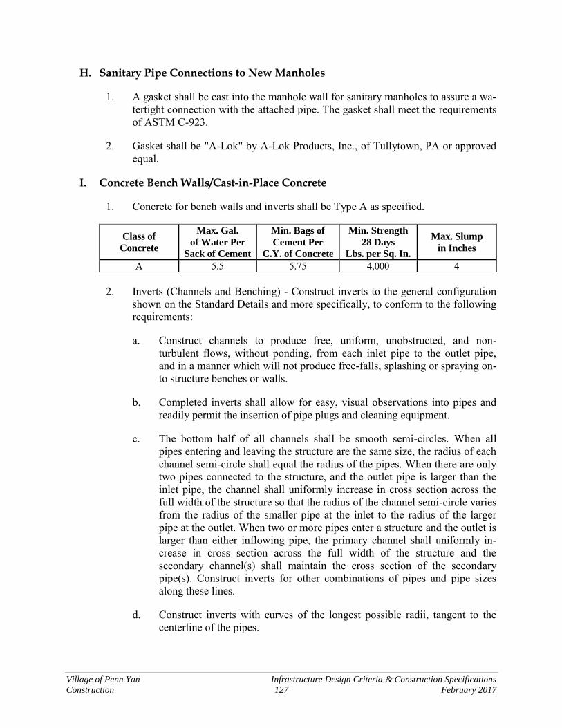
Village of Penn Yan Infrastructure Design Criteria & Construction Specifications
Construction 127 February 2017
H. Sanitary Pipe Connections to New Manholes
1. A gasket shall be cast into the manhole wall for sanitary manholes to assure a wa-tertight connection with the attached pipe. The gasket shall meet the requirements of ASTM C-923.
2. Gasket shall be "A-Lok" by A-Lok Products, Inc., of Tullytown, PA or approved equal.
I. Concrete Bench Walls/Cast-in-Place Concrete
1. Concrete for bench walls and inverts shall be Type A as specified.
Class of
Concrete
Max. Gal.
of Water Per
Sack of Cement
Min. Bags of
Cement Per
C.Y. of Concrete
Min. Strength
28 Days
Lbs. per Sq. In.
Max. Slump
in Inches
A 5.5 5.75 4,000 4
2. Inverts (Channels and Benching) - Construct inverts to the general configuration shown on the Standard Details and more specifically, to conform to the following requirements:
a. Construct channels to produce free, uniform, unobstructed, and non-turbulent flows, without ponding, from each inlet pipe to the outlet pipe, and in a manner which will not produce free-falls, splashing or spraying on-to structure benches or walls.
b. Completed inverts shall allow for easy, visual observations into pipes and readily permit the insertion of pipe plugs and cleaning equipment.
c. The bottom half of all channels shall be smooth semi-circles. When all pipes entering and leaving the structure are the same size, the radius of each channel semi-circle shall equal the radius of the pipes. When there are only two pipes connected to the structure, and the outlet pipe is larger than the inlet pipe, the channel shall uniformly increase in cross section across the full width of the structure so that the radius of the channel semi-circle varies from the radius of the smaller pipe at the inlet to the radius of the larger pipe at the outlet. When two or more pipes enter a structure and the outlet is larger than either inflowing pipe, the primary channel shall uniformly in-crease in cross section across the full width of the structure and the secondary channel(s) shall maintain the cross section of the secondary pipe(s). Construct inverts for other combinations of pipes and pipe sizes along these lines.
d. Construct inverts with curves of the longest possible radii, tangent to the centerline of the pipes.

Village of Penn Yan Infrastructure Design Criteria & Construction Specifications
Construction 128 February 2017
e. Construct the benching by solidly filling in the area between the channel and the structure walls. Slope the top surface of the benching towards the channel, at a pitch of approximately ½-inch/foot so that the liquid on the bench will easily drain into the channel. Provide as much bench area as is possible for standing on and make surface slightly roughened to attain a skid resistant finish.
f. Where the top of benching intersects the channel, the resulting edge shall be rounded to a radius of approximately 1/4" - 3/4". Where channels meet to form an acute angle, provide a rounded intersection with a radius of about 1".
3. Penetrations Through Concrete - Only where absolutely necessary, penetrations shall be made through concrete by core drilling or by other approved means which will produce a hole in the minimum possible size and in a manner which will not affect the structural integrity of the concrete. After inserting the item which is penetrating the wall, carefully and neatly fill the annular spaces with hy-draulic cement.
J. Cleanout Frame and Cover
Frames and covers for cleanout inspection ports shall be cast iron with blind pick hole meeting ASTM A48 Class 30 or better. The top surface shall have a non-skid surface and shall bear the title "SANITARY". The frame and covers shall be as manufactured by Sy-racuse Castings model 4155 or approved equal.
K. Orientation of Covers, Grates, and Rungs
1. General - The intent of this paragraph is to provide guidance in the selection of the location of the frame and cover. The location should provide for the safety of all, during and after construction of the work, provide for convenient ingress and egress, and minimizes adverse visual impacts. Orient the location of covers and steps by using the following criteria, with precedence given in the order present-ed.
2. Safety - Give primary concern to safety considerations for providing convenient access to structure interiors.
3. Covers and Pavements - To avoid future problems with snow removal or street cleaning, orient covers to lie completely outside of paved surfaces, including walks and roadways. If this cannot be accomplished, locate cover completely in pavement. Covers partially in pavement are not permitted without the prior ap-proval of the Village. When covers occur in paved areas, locate entirely within a single traffic lane and as near to the edge of pavement as is possible, but no closer than 8" from the edge of pavement. Frames and covers shall be located below fin-ished grade of finished surface, minimum of ¼-inch.

Village of Penn Yan Infrastructure Design Criteria & Construction Specifications
Construction 129 February 2017
4. Ingress/Egress - Coupled with the above, convenient and safe access to within the structure must be evaluated. Coordinate cover location with pipe openings, struc-ture benches and inverts, safety landings and the like. Make every effort to locate steps on a wall with no pipe penetrations and, where steps are not specified to be provided, consideration shall be given to the safest means of seating the feet of ladders which will be used for access to structure interiors.
5. Non-compliance - Non-compliance with the requirements of this paragraph may result in Village's disapproval of the entire structure. When requested, the Village will assist in determining the optimum location of covers, grates, and rungs.
L. Construction of New Manholes and Structures
1. Precast Bases: Place stone bedding, level, and tamp firmly in place. When abso-lutely necessary, pea stone may be used for minor grade adjustments in the stone bedding, but the depth shall not exceed 3/4". Carefully lower precast base in place, taking extra care not to shift the stone bedding, and align all openings with the pipes to be connected. Leveling of the base by tamping or pounding on the top of the precast product is prohibited. If base is not level, lift it out, readjust stone bedding, and reset base. Continue this procedure until base is level.
2. Precast Risers and Top Sections: Thoroughly clean all joints of precast sections and install jointing material. Carefully set precast sections in place, making sure that jointing material is not displaced and that a good seal is attained. Fill all lift-ing holes with hydraulic cement.
3. Filling Precast Section Joints: Fill interior and exterior joints with hydraulic ce-ment. Cover inside and outside of joint with two coats of Koppers Bitumastic Super Service Black Coal Tar or approved equal.
4. Inverts: Inverts built upon precast base shall be constructed of concrete brick, half sections of sewer pipe or be cast in place. Care shall be exercised in forming in-verts to give proper slope and shape to each channel. Bench walls shall be constructed of sewer brick and bench filled with concrete. Bench walls shall be carried a minimum of one brick course above top of highest pipe entering the manhole. Slope the top surface of the benching towards the channel as a pitch of approximately 1/2"/ft.
5. Roof Slabs
a. Slab shall be formed to fit into ends of vertical pipe and shall have full bear-ing for its entire circumference. The slab shall be set in bed of cement mortar.
b. Opening diameter shall match manhole casting inside base diameter.
c. The location of center of opening for frame and cover shall be 1'-6" from inside of manhole wall unless otherwise noted.

Village of Penn Yan Infrastructure Design Criteria & Construction Specifications
Construction 130 February 2017
6. Chimneys
a. Precast grade rings set in mortar shall be used to bring manhole frames to grade, maximum 8" height for grade ring.
7. All manhole frames shall be set in mortar and concrete fill placed around the out-side and kept 2" below the top of the frame.
8. The Developer shall be responsible for maintaining and keeping all manholes clean and free of debris until completion of the project.
M. Connection to Existing Sanitary Manholes
1. Where noted, the Developer shall make connection to existing manhole. The use of excessive force or blunt instruments is prohibited in installing the pipe into the existing wall. If a stub exists and matches the size of the new sewer, the Develop-er shall connect to the stub. The stub to manhole connection should be checked and repaired if damaged or in poor shape. If stub does not match the size of the new sewer, the stub shall be removed and the new sewer shall be inserted into the manhole.
2. In making the connection to existing manhole(s), it shall be the Developer's re-sponsibility to dewater the structure in order to make the connection.
3. The manhole shall be visually inspected by the Village for tightness of fit at all new joints.
N. Installation of Precast Manholes
1. Precast Bases: Place stone bedding, level, and tamp firmly in place. When abso-lutely necessary, pea stone may be used for minor adjustments in final leveling, but the depth shall not exceed 3/4". Carefully lower precast base in place, taking extra care not to shift the stone bedding, and align all openings with the pipes to be connected. Leveling of the base by tamping or pounding on the top of the pre-cast product is prohibited. If base is not level, lift it out, readjust stone bedding, and reset base. Continue this procedure until base is level.
2. Precast Risers and Top Sections: Thoroughly clean all joints of precast sections and install jointing material. Carefully set precast sections in place, making sure that rubber gasket jointing material is not displaced and that a good seal is at-tained. Fill all lifting holes with hydraulic cement.
O. Testing
1. Completed sanitary manholes only shall be subject to vacuum tests. The inlet and outlet pipe for the manholes shall be plugged with a plug that allows no leakage.
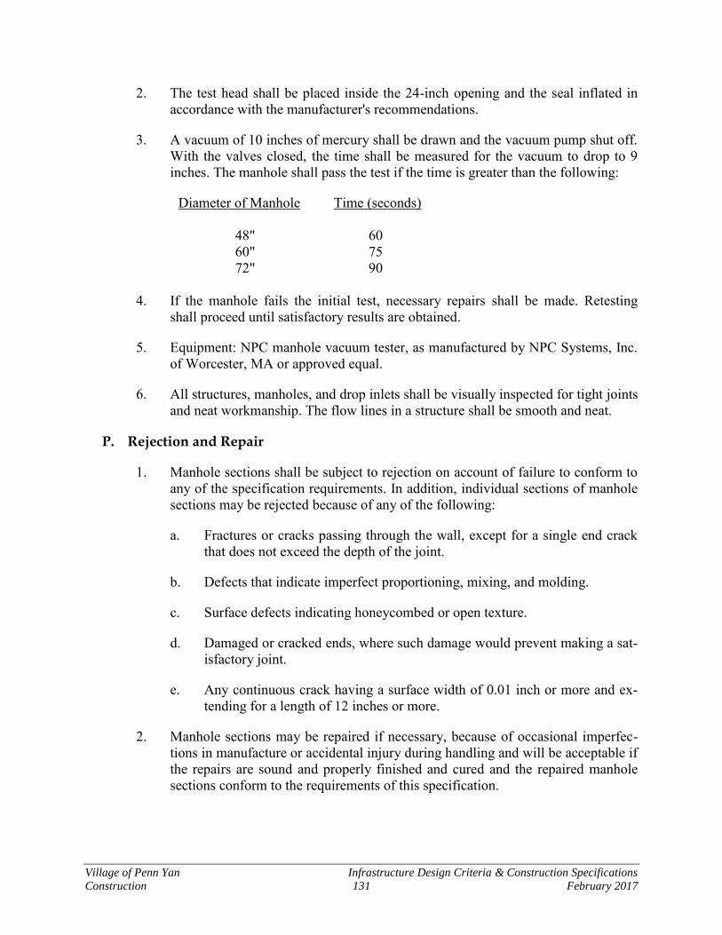
Village of Penn Yan Infrastructure Design Criteria & Construction Specifications
Construction 131 February 2017
2. The test head shall be placed inside the 24-inch opening and the seal inflated in accordance with the manufacturer's recommendations.
3. A vacuum of 10 inches of mercury shall be drawn and the vacuum pump shut off. With the valves closed, the time shall be measured for the vacuum to drop to 9 inches. The manhole shall pass the test if the time is greater than the following:
Diameter of Manhole Time (seconds) 48" 60 60" 75 72" 90
4. If the manhole fails the initial test, necessary repairs shall be made. Retesting shall proceed until satisfactory results are obtained.
5. Equipment: NPC manhole vacuum tester, as manufactured by NPC Systems, Inc. of Worcester, MA or approved equal.
6. All structures, manholes, and drop inlets shall be visually inspected for tight joints and neat workmanship. The flow lines in a structure shall be smooth and neat.
P. Rejection and Repair
1. Manhole sections shall be subject to rejection on account of failure to conform to any of the specification requirements. In addition, individual sections of manhole sections may be rejected because of any of the following:
a. Fractures or cracks passing through the wall, except for a single end crack that does not exceed the depth of the joint.
b. Defects that indicate imperfect proportioning, mixing, and molding.
c. Surface defects indicating honeycombed or open texture.
d. Damaged or cracked ends, where such damage would prevent making a sat-isfactory joint.
e. Any continuous crack having a surface width of 0.01 inch or more and ex-tending for a length of 12 inches or more.
2. Manhole sections may be repaired if necessary, because of occasional imperfec-tions in manufacture or accidental injury during handling and will be acceptable if the repairs are sound and properly finished and cured and the repaired manhole sections conform to the requirements of this specification.
Village of Penn Yan Infrastructure Design Criteria & Construction Specifications
Construction 132 February 2017
Q. Marking and Painting
1. Name and trademark of the manufacturer shall be clearly marked on each man-hole section.
2. Marking shall be indented into the manhole bases, risers, and top sections or shall be painted thereon with waterproof paint.
3. The precast manufacturer shall apply one coat (12 mils minimum per coat) of bi-tumastic coal tar to all internal areas of all precast sections used for sanitary manholes in accordance with the paint manufacturer's instructions. This material shall be Koppers Super Service Black or approved equal.
4. Immediately after installation is completed, the Developer shall touch up all marks, scars, and imperfections found and paint all interior surfaces not factory coated with two coats of coal tar, Koppers Super Service Black or approved equal.
5. Cover inside and outside of joints all around with flexible joint sealer and two (2) coats of Koppers Super Service Black or approved equal.

Village of Penn Yan Infrastructure Design Criteria & Construction Specifications
Construction 133 February 2017
Section 14 Water Supply
14.1 Water Mains and Appurtenances
A. Excavation, Grading, and Shoring
1. General: The Developer shall verify that points of connections to existing pipes have been excavated and the Village of Penn Yan has issued an authorization to proceed with the work as shown, or with modifications. The installation of water mains and appurtenances will be in accordance with the requirements of the Vil-lage of Penn Yan and New York State Department of Health. The Village of Penn Yan’s interest in the proper installation of water mains is related to the protection of other public facilities being installed as part of the project that will be dedicated to the Village of Penn Yan.
2. Under normal conditions, the excavation shall be vertical open cut from the ground surface. Tunneling beneath trees and certain surface structures may be re-quired.
3. Bottom of excavations shall be finish graded by hand methods to receive bedding. The stone bedding shall be placed, compacted, and trimmed by hand to ensure the grade as necessary or as detailed.
B. Storage and Handling
1. Stockpiling of earth spoil or excess earth material on the site or storage of exca-vated materials for reuse shall be done in a manner which will not hinder the progress of the work; cause any nuisance; or cause spillage or tracking of materi-als from the transporting vehicle onto public highways or cause an inconvenience to adjacent property owners.
2. Obstruction of roads, driveways, sidewalks, or interference with drainage along gutters, ditches, or drainage channels with stored material is not permitted.
3. Promptly remove materials not specified to be stored or reused. Burning of mate-rials at the site is not permitted. Such materials shall be disposed of off-site in conformance with applicable legal requirements.
4. Topsoil suitable for final placement and grading shall be excavated and stockpiled on-site for future use. The stockpile shall be well-shaped and graded in order to shed water and to avoid contamination by other granular or earth materials tempo-rarily stockpiled on-site.
C. Job Conditions
1. Keep graded surfaces well drained, but avoid erosion. Do not place earth fill on wet grade, in water, or over ice or snow.
Village of Penn Yan Infrastructure Design Criteria & Construction Specifications
Construction 134 February 2017
2. Filling with frozen materials or when materials already in place are frozen, is not permitted.
3. Provide and maintain suitable temporary crossings over open ditches when re-quired to maintain access.
4. The Contractor shall be responsible for all damage or injury done to pipes, struc-tures, pavement, property or person as a result of excavations required to complete the work.
5. When excavating in or adjacent to the traveled portion of highways, take whatev-er measures are necessary to protect the road surfaces from becoming undermined.
D. Methods Of Control For Excavations And Grading
1. The Developer shall be responsible for the proper layout of utilities, structures, and drainage. He shall maintain adequate stakeout control for inspection of the work and to accurately complete construction.
E. Limit Of Excavation For Pipelines
1. Trenches shall be excavated as shown on the Contract Drawings.
F. Limit Of Excavation For Structures
1. Excavations for structures and facilities shall be of sufficient size to give suitable room for proper construction procedures and no larger.
G. Site Grading
1. Prior to start of work, the Developer shall verify that all boundaries of temporary and permanent easements and property lines are clearly marked in the field so that the work will not violate these boundaries.
2. The Developer shall verify the locations and character of structures, underground lines, and subsurface conditions and verify that the described work will not ad-versely affect them.
3. The Developer shall dispose of excess suitable excavated material on-site.
4. Subgrade surfaces shall drain, be compacted, and well graded.
H. Storage Of Materials
1. All excavated materials shall be stored in locations so as not to endanger the work, and so that easy access may be had at all times to all parts of the excava-tion. Stored materials shall be kept neatly piled and trimmed, so as to cause as
Village of Penn Yan Infrastructure Design Criteria & Construction Specifications
Construction 135 February 2017
little inconvenience as possible to other Contractors on site or to adjoining proper-ty owners.
2. Topsoil suitable for final grading shall be removed and stored on-site separately from other excavated material.
14.2 Pipe and Structure Backfill
A. General
1. Provide and maintain suitable temporary crossings over open trenches where nec-essary to maintain access.
2. Any backfill material over trenches that settle and/or erode during a period of two (2) years after the date of final acceptance shall be repaired by the Developer up-on receipt of written notice from the Village.
3. The Developer shall take precautions to protect from harm the work of other con-tractors on site, existing facilities, as well as adjacent property. The Developer shall be responsible for all damage or injury done to pipes, structures, pavement, property or persons due to improper placing or compacting of backfill. The De-veloper shall repair such damaged property or item to the satisfaction of the property owner, public agency having jurisdiction and/or Village at no additional cost.
4. When it is necessary to haul material over the streets or pavements, the Developer shall provide suitable tight vehicles so as to prevent deposits on the streets or pavements. In all cases where any materials are dropped from the vehicles, the Developer shall clean up the same as often as directed and keep the crosswalks, streets, and pavements clean and free from dirt, mud, stone, and other hauled ma-terial.
5. Flagmen, guards, barricades, lights, services, and other items needed for the pro-tection of persons and property shall be furnished and maintained by the Developer in accordance with MUTCD/NYSDOT standards.
6. The Developer shall remove any waste material or other debris that has accumu-lated as a result of the work of this section and dispose in conformance with applicable legal requirements.
7. The various types of backfill material to be utilized on-site are specified below and shall be used as described unless specifically shown otherwise on the draw-ings.
8. Mechanical, vibratory, pneumatic tampers or other method as approved by the Village of Penn Yan shall be required.
9. Water in sufficient quantity may be required to assure compaction.

Village of Penn Yan Infrastructure Design Criteria & Construction Specifications
Construction 136 February 2017
10. Lift thickness, and the compactive capabilities of the equipment used, shall be continually monitored by the Developer to obtain the compaction efforts required for all materials used for backfill.
B. General Backfilling Requirements
1. The Contractor shall be responsible for providing all necessary fill materials.
2. All excavations shall be backfilled to the original surface of the ground. Backfill-ing shall be done with suitable excavated materials satisfactorily compacted.
3. Excavated material unsuitable for backfilling shall not be used, and shall be stock-piled or removed from the site according to the following:
a. Unsuitable material shall fall into two specific categories. The first shall be that material which would be unsuitable under any circumstances. Material containing humus, spongy material, roots, stumps, muck, peat, and any oth-er objectionable material. This material shall be disposed of in an approved off-site spoil area.
b. The second category shall consist of material which is unsatisfactory for backfill because of its moisture content at the time of excavation. This ma-terial shall be stockpiled in approved areas on the Project site. This stockpiled material, when satisfactory for backfill, shall be used in other ar-eas lacking backfill.
4. As required, sufficient water may be added during compaction to assure a com-plete consolidation of the material.
5. The Developer shall make up any settlement of trenches or embankments with suitable material and stabilize at no additional cost to the Village. This work shall be performed promptly.
C. Settlement
1. Repair to proper grade any settlement of slab, pavement, utility structure, lawn, etc. adversely affected by settlement within two (2) years after final acceptance at no expense to Village.
14.3 Installation of Water Mains and Appurtenances
A. Handling Materials
1. Proper equipment, tools, and facilities shall be provided and used for safe and convenient handling of materials. Pipe, fittings, valves, and hydrants shall be carefully lowered into the trench piece by piece in such a manner as to prevent damage. Under no circumstances shall materials be dumped or dropped into the trench.
Village of Penn Yan Infrastructure Design Criteria & Construction Specifications
Construction 137 February 2017
B. Laying Pipe
1. Water mains and appurtenances shall be installed with a minimum cover of 5'-0". The pipe and fittings shall be laid in accordance with pipe manufacturer's instruc-tions. The pipe and fittings shall be inspected by the Contractor for defects before installation. Every precaution shall be taken to prevent foreign material from en-tering the pipe while it is being placed in the line. If the pipe laying crew cannot put the pipe into the trench and in place without getting earth into it, the Engineer may require that, before lowering the pipe into the trench, a heavy tightly woven canvas bag of suitable size shall be placed over each end and left there until the connection is to be made to the adjacent pipe. During the pipe laying operations, tools, clothing, or other materials shall not be placed in the pipe.
2. At times when pipe laying is not in progress, the open ends of the pipe shall be closed by a watertight plug or other means approved by the Engineer for the Vil-lage. This provision shall apply during the noon hour as well as overnight. If water is in the trench, the plug shall remain in place until the trench is pumped dry. No pipe shall be laid in water or when, in the opinion of the Engineer, the trench conditions are unsuitable.
C. Cutting Pipe
1. The cutting of pipe for inserting valves, fittings, or closure pieces shall be done in a neat and workmanlike manner without damage to the pipe, and so as to leave a smooth end at right angles to the axis of the pipe. The cut ends shall be tapered with a file or portable grinder to the same taper as that of the factory beveled end.
D. Permissible Deflection at Joints
1. Wherever it is necessary to deflect pipe from a straight line, either in the vertical or horizontal plane, the joint deflection shall not exceed 5 degrees for sizes 4" through 12".
E. Making Joints
1. Joints shall be made in accordance with the recommendations of the manufacturer or as specified herein. Two brass wedges shall be tightly inserted in opposite sides of each joint in a manner that will insure electrical conductivity across the joint.
F. Installing Fittings and Valves
1. Install fittings and valves where indicated on the drawings. Additional fittings, not shown on the drawings, also shall be provided if needed to install the water main and make connections to the existing system. Fittings not indicated or called for shall be used only after approval by the Utilities Manager. The additional fittings shall be shown on the Record Drawings.
Village of Penn Yan Infrastructure Design Criteria & Construction Specifications
Construction 138 February 2017
2. A valve box and cover shall be provided for every valve. The valve box shall not transmit shock or stress to the valve and shall be centered and plumb over the op-erating nut. The cover shall be adjusted to meet the finished grade.
G. Setting Hydrant Units
1. All hydrants shall stand plumb and shall have pumper nozzles facing the road. Hydrants shall be set with the ground line mark at the existing grade or as directed by the Engineer for the Village. Each hydrant shall be connected to the main with a 6" branch controlled by an independent 6" gate valve. A carpenter's or mason's level shall be used to set the hydrant branches level with the water main so that the hydrant will stand plumb. Use barrel extensions as required.
2. Concrete blocking at the base of the hydrant may be deleted from the hydrant branch installation, if the Contractor uses mechanical joint anchoring fittings as manufactured by U.S. Pipe and Foundry Company. Securely anchor the hydrant branch to the water main including all joints. Provide concrete blocks for the hy-drant barrel as shown in the Standard Details, regardless of branch anchorage used.
H. Painting
1. The outside surfaces of hydrants above finished grade and all valve box covers shall be thoroughly cleaned and painted upon completion of all work.
2. Paint with two coats of New Color Horizons High Gloss Finish as manufactured by Rust-Oleum Corporation. Color to be selected by the Municipal Utilities Board.
I. Connection to Existing Mains
1. After testing and disinfection of new water mains is complete, connections shall be made to existing mains where indicated on the drawings by shutting down the existing main and making a non-pressure connection or by installing a tapping sleeve and valve.
2. Non-pressure connections shall be made with a minimum of disruption of ser-vice. The existing main shall be cut and connecting pieces or adapters shall be installed as detailed or as needed to make a proper connection.
J. Special Requirements for Protection of Water Mains
1. All work near and under existing water mains shall be in accordance with re-quirements of the Utilities Manager.
2. Water mains shall be laid at least 10 feet horizontally from sanitary sewers, storm sewers, and manholes, whenever possible. Water mains laid closer than
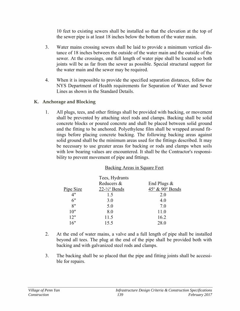
Village of Penn Yan Infrastructure Design Criteria & Construction Specifications
Construction 139 February 2017
10 feet to existing sewers shall be installed so that the elevation at the top of the sewer pipe is at least 18 inches below the bottom of the water main.
3. Water mains crossing sewers shall be laid to provide a minimum vertical dis-tance of 18 inches between the outside of the water main and the outside of the sewer. At the crossings, one full length of water pipe shall be located so both joints will be as far from the sewer as possible. Special structural support for the water main and the sewer may be required.
4. When it is impossible to provide the specified separation distances, follow the NYS Department of Health requirements for Separation of Water and Sewer Lines as shown in the Standard Details.
K. Anchorage and Blocking
1. All plugs, tees, and other fittings shall be provided with backing, or movement shall be prevented by attaching steel rods and clamps. Backing shall be solid concrete blocks or poured concrete and shall be placed between solid ground and the fitting to be anchored. Polyethylene film shall be wrapped around fit-tings before placing concrete backing. The following backing areas against solid ground shall be the minimum areas used for the fittings described. It may be necessary to use greater areas for backing or rods and clamps when soils with low bearing values are encountered. It shall be the Contractor's responsi-bility to prevent movement of pipe and fittings.
Backing Areas in Square Feet
Tees, Hydrants Reducers & End Plugs & Pipe Size 22-½o Bends 45o & 90o Bends 4" 1.5 2.0 6" 3.0 4.0 8" 5.0 7.0 10" 8.0 11.0 12" 11.5 16.2 16" 15.5 28.0
2. At the end of water mains, a valve and a full length of pipe shall be installed
beyond all tees. The plug at the end of the pipe shall be provided both with backing and with galvanized steel rods and clamps.
3. The backing shall be so placed that the pipe and fitting joints shall be accessi-ble for repairs.
Village of Penn Yan Infrastructure Design Criteria & Construction Specifications
Construction 140 February 2017
L. Repairs
1. If it is necessary to repair or relay a section of pipe due to broken pipe, faulty line or grade, or any other reason, repair clamps shall not be used, but the pipe to be repaired shall be removed and replaced with new pipe.
14.4 Installation of Water Services
A. General
1. Services shall not be connected until testing and disinfecting of the water main is complete. Services shall be installed to within 1.0 foot from the right-of-way or as directed by the Engineer for the Village.
B. Preparation of Bed
1. The service line bed shall be prepared so that the full length of the line is in-stalled with a minimum cover of 5'-0". The bed and backfill over the copper service line shall be free from sharp or angular stones and any other material that might puncture or damage the service line. Provide select granular materi-al if needed to cushion and protect the service from damage.
C. Installing Water Services
1. Tubing shall be uncoiled in such a manner as to prevent damaging, denting or kinking the line. The tubing, fittings, and appurtenances shall be inspected for defects before installation. Every precaution shall be taken to prevent foreign material from entering the tubing. When installation is not in progress, the open ends of the line shall be closed by temporary plugs. Install tubing with a horizontal expansion loop at the water main connection. A single piece of ser-vice line shall be used from corporation stop to the curb stop.
D. Corporation Stop Installation
1. A corporation stop shall be installed at the main for each water service. The main shall be drilled and tapped directly and the corporation stop inserted. Af-ter the connection has been made to the service pipe and the curb stop, the corporation stop shall be left in the full open position.
2. Tapping Saddles shall be utilized for all services greater than 1” diameter.
E. Installing Curb Stops and Curb Boxes
1. Locate curb stops 1.0' inside the street right-of-way unless otherwise shown. The curb boxes shall be installed vertically over the center of the stop with the lid extending 1/2 inch above finished grade.
Village of Penn Yan Infrastructure Design Criteria & Construction Specifications
Construction 141 February 2017
F. Crossing Under Pavement
1. Water services under existing pavements, curbs, and gutters shall be installed by drilling, jacking, boring, or driving, or any other method satisfactory to the authorities having jurisdiction over the street. Open cut installation of the ser-vice lines will not be permitted nearer than 2.0 feet to the edge of existing pavement unless authorized.
14.5 Preparation for Use
A. Water Supply
1. Water for testing and flushing shall be obtained from the existing water sys-tem. Arrangements shall be made with the Utilities Manager for payment of water used.
B. Flushing
1. Flush mains and services before testing. Minimum flushing velocity shall be 2.5 feet per second.
C. Testing Water Mains and Hydrant Units
1. Before testing, sections adjacent to the test section shall be filled with water. Furnish all water, equipment, connections, piping, meters, measuring devices, pumps, and temporary enclosures necessary to perform the required tests, sub-ject to the review and approval by the Utilities Manager. Testing shall be made on sections of water main not exceeding 2,000 feet in length.
2. Testing shall meet the minimum requirements of AWWA C-600, except where more rigid requirements are established by these specifications. Before apply-ing test pressure, all air shall be expelled from the pipe. After the pipe has been filled, it shall be subjected to hydrostatic pressure of 50 psi above normal line pressure or a minimum of 150 psi for a period of two hours, with zero pressure loss. There shall be no allowable leakage as part of testing within the Village of Penn Yan.
3. Test pressure shall be based on the elevation of the lowest point under test. Pressure shall be applied by a pump connected to the pipe. The pump, pipe, connections, gauges, and measuring devices shall be calibrated to the satisfac-tion of the Engineer for the Village.
4. A preliminary test of 50 psi above normal line pressure or a minimum of 150 psi shall be performed by the Contractor. After the preliminary test is satisfac-tory, the Engineer shall be given 24 hours’ notice and a final test performed.
Village of Penn Yan Infrastructure Design Criteria & Construction Specifications
Construction 142 February 2017
5. Should any test disclose leakage, the defect shall be located and repaired.
D. Testing Services
1. During installation, test each service before backfilling by subjecting the ser-vice to normal line pressure. Open the corporation stop, expel all air from the line, close the curb stop, and observe the line for leakage. Repairs, if required, shall be made and the service retested until no leakage is observed.
E. Disinfection
1. All water mains and appurtenances shall be disinfected in accordance with AWWA C 651 Disinfecting Water Mains, and the requirements of the New York State Department of Health. The requirements of NYS Department of Health shall govern when there is a conflict. Use 50 ppm initial chlorine dose. Disinfectant shall remain in the system for a period of 24 hours after which the residual shall be at least 10 ppm. The system shall then be drained and refilled with clean water.
2. A water sample shall be collected by the Contractor and analyzed by a New York State Department of Health approved testing laboratory for bacteriologi-cal content. The work will not be accepted until a report is submitted to the Engineer for the Village showing that a water sample is satisfactory and the system is ready for use.

Village of Penn Yan Infrastructure Design Criteria & Construction Specifications
Construction 143 February 2017
Section 15 Electrical Construction
15.1 Electrical Installations A. The “Penn Yan Municipal Utilities Specifications for the Installation of Electric Services
and Meters” should be referenced during construction of electrical service connections and appurtenances.
15.2 Excavation, Installation and Backfill Requirements
A. General
1. The applicant shall have completed the installation of other utilities including but not limited to water mains and services, storm sewers and laterals, and sanitary sewers and laterals prior to requesting the installations of any underground elec-tric distribution. In addition, the aforementioned utilities shall be installed complete in all locations where they pass under proposed electric system. The ap-plicant shall have all grading completed within a (+) or (-) 6" tolerance in those areas where the electric distribution is to be constructed prior to requesting instal-lation. Grade stakes and property easement or right-of-way line stakes shall be installed by the applicant prior to any installation of the electric system.
B. Excavation
1. In addition to the above requirements, the applicant shall dig all trenches in the locations shown on marked prints provided by the developer or contractor and/or as directed by the employees of the electric system in the field. The trenches shall be three (3) feet deep and two (2) feet wide. If C.A.T.V. and telephone are buried in the trench with electric there will be a separation of one (1) foot horizontal and one (l) foot vertical.
2. Trenches shall be kept free of all building materials and under no circumstances shall cable be installed where any construction, debris or building material are visible in the excavation.
3. The applicant shall be solely responsible for scheduling of all trenching with the Penn Yan Municipal Utilities Board in order to ensure the materials and manpow-er are available to properly install the electric cables promptly, in order to avoid a prolonged opening and resulting degradation of the trench.
4. In the event a delay is encountered in the installation through no fault of the Penn Yan Municipal Utilities Board and the trenches must be cleaned out, the applicant shall perform said work at no cost to the Penn Yan Municipal Utilities Board.
5. The applicant is hereby advised that excavation for the electric distribution sys-tems in the winter must be very closely coordinated with the Penn Yan Municipal
Village of Penn Yan Infrastructure Design Criteria & Construction Specifications
Construction 144 February 2017
Utilities Board and backfilled minimum of one (1) foot over the cable/conduit shall be installed by the applicant in order to preclude cable damage by frozen chunks of earth.
C. Installation
1. The Penn Yan Municipal Utilities Board shall furnish and install or cause to be installed, all primary and secondary distribution cables and appurtenances within the trenches as excavated under paragraph A & B.
2. Such work shall be performed in a workman like manner and said materials and installation shall be the full responsibility of the Penn Yan Municipal Utilities Board.
D. Backfill
1. The applicant shall backfill the trench when requested by and in such a manner as directed by the Penn Yan Municipal Utilities Board. The first one (1) foot of backfill shall be select earth to avoid damage to the cable/conduit. The Penn Yan Municipal Utilities Board will furnish "Warning Tape" to be placed in trench, the remainder of the trench may be machine backfilled with excavated material providing no stones, rocks, debris, building material or other foreign matter with any dimension over two (2) inches is included.
2. The trench may be mounded to provide for settlement; however, proper trench maintenance shall be performed to prevent any damage degradation of the instal-lation.
E. Inspection
1. All trenching and backfilling operations shall be subject to inspection and approv-al of the Penn Yan Municipal Utilities Board prior to installation and/or operation of the distribution system.
2. Should a fault occur when the system is energized, the Penn Yan Municipal Utili-ties Board shall locate and excavate same and make necessary repairs or replacement.
3. In the event it is found that said fault was caused by any rock or foreign object in contact with the cable/conduit as a result of improper bedding or backfilling, the Penn Yan Municipal Utilities Board shall back-charge the applicant the cost of repair and/or replacement of same.
F. Appurtenances
1. The Penn Yan Municipal Board shall furnish and install and/or cause to be in-stalled all appurtenances of the distribution system including but not limited to transformers pads, transformers and switches, power pedestals, wire and conduits
Village of Penn Yan Infrastructure Design Criteria & Construction Specifications
Construction 145 February 2017
for primary and secondary conductors. The applicant shall provide the Penn Yan Municipal Utilities Board with accurate maps and stakes indicating lot or ease-ment lines, utility locations and finished grades at the location of the appurtenances.
2. The Penn Yan Municipal Utilities Board shall furnish and install pad mount trans-formers only. Underground transformer vault installations must be approved by the Penn Yan Municipal Utilities Board on a case by case basis.
3. The Penn Yan Municipal Board shall install all equipment at such locations and elevations such that the transformer and other equipment will be installed to pre-clude silting around or water damage from ponding.
4. In event the applicant for any reason changes the grading in the areas of the equipment following installation of same, such that damage or degradation of the equipment could occur, or such that an unsightly installation is caused, the appli-cant shall reimburse the Penn Yan Municipal Utilities Board for the cost of reconstructing said equipment to the proper elevations.
G. Distribution System Maintenance
1. The applicant shall provide the Penn Yan Municipal Utilities Board a complete as-built map of the development prior to dedication of utilities and/or prior to re-questing service connections to the units.
2. The as built map shall be reproducible and shall show all right-of-way lines, easement lines and as constructed locations of all water lines and services, storm sewers and laterals, sanitary sewers and laterals, gas mains and services and tele-phone cables and services, and electric distribution lines, transformers, pedestals or hand holes, vaults and services.
3. Prior to dedication or connection of services in undedicated areas, the applicant shall be responsible for all damage or degradation of the distribution system and appurtenances, caused by construction activity or any other actions on the parts of the applicant.
4. The Penn Yan Municipal Utilities Board shall make necessary repairs and/or re-placement of cables and equipment damaged by the applicant during this period and shall be reimbursed by the applicant for the cost of said repairs and/or re-placements.
5. Following dedication and/or connection of all services, the Penn Yan Municipal Board assumes responsibility for the distribution system within the limits of its agreement with the applicant and/or such clauses and contingencies which may exist on easements, documents or other right-of-way which may exist.
Village of Penn Yan Infrastructure Design Criteria & Construction Specifications
Construction 146 February 2017
15.3 Services
A. Building Installations
1. The service laterals between the Penn Yan Municipal Utilities Board underground distribution system and the applicants point (s) of entrance shall be furnished and installed by the applicant at the applicant’s expense.
2. The applicant will be billed for all electric installations performed by Penn Yan Municipal as per the Public Service Commission tariff in effect for Penn Yan Municipal Utilities at the of construction for the applicant’s project.
3. The service (s) shall be located as directed by the Penn Yan Municipal Utilities Board and/or as shown on plans previously approved by the Penn Yan Municipal Utilities Board.
4. The service (s) shall be of adequate capacity and acceptable to the Penn Yan Mu-nicipal Utilities Board in regard to shielding, insulation level and general quality, and in all respects shall be in accordance with the latest revision of the national electric code and subject to the requirements of the New York State Fire Under-writers and/or any other authorities claiming jurisdiction. Said service shall not be connected until a certificate has been issued by New York State Fire Underwrit-ers, or other competent inspecting agency.
5. If the service is too long in length for maintaining a good voltage level, a primary cable and transformer will have to be installed.
6. The electrician and/or contractor shall use cable to meet the Penn Yan Municipal Utilities Board specifications
7. The service trench(es) shall be excavated, and the cables installed, and the trench-es backfilled as specified under Section 2-B&D.
8. All service installations shall be subject to inspection and approval to the Penn Yan Municipal Utilities Board.
9. Upon completion of the installation of service by the applicant, and the receipt of the New York State Board of Fire Underwriters or other competent inspection certificate of approval of the occupancy electrical wiring, the Penn Yan Municipal Utilities Board will make the final connection at the distribution system trans-former or pedestal and install the meter for the applicant. A similar certificate must be furnished for changes in or additions to the wiring.
10. All underground service laterals shall be so located and so arranged so that the lateral(s) will always be owned and maintained by the applicant and/or subse-quent purchasers of the occupancy being served by same.
Village of Penn Yan Infrastructure Design Criteria & Construction Specifications
Construction 147 February 2017
B. Metering
1. Meters shall be installed by the Penn Yan Municipal Utilities Board on the out-side of building at a location approved by the Penn Yan Municipal Utilities Board.
2. The applicant shall furnish and install all meter mounting equipment such as me-ter cabinets, metering transformer enclosures or mounting devices and any metering transformers required.
3. Metering mounting boxes shall not be used as junction boxes
4. When metered current exceeds 320 amperes, metering transformers will be re-quired.
C. Trailer Park Installations
1. The Penn Yan Municipal Utilities Board will establish one (1) point of service connection for trailer park installations at no charge to the park owners. Such one (1) point of service connection will be determined by the Penn Yan Municipal Utilities Board on load center location. Any further points of service connection will be furnished and installed by the park owner at his expense. All trailer site lo-cations will be provided by owner, with a safe and adequate meter module unit consisting of an integral meter base, a properly sized main line multibreaker pro-tective device with secure capability of being locked in either the open or closed position, and a plugin facility for trailer temporary connection (permanent trailer locations shall be connected directly to the multibreaker load side connections). Meter modules shall be not less than 100 ampere capacity for electric heated trail-ers.
15.4 Lighting
A. General
The Developer may provide adequate street lighting and fixtures at the locations shown on the plans and as directed by the Village Board. The Village Board shall require the installation of street lights at all intersections by the Developer.
B. Materials
Wiring, light poles, lights and foundations shall meet N.E.C. and the National Board of Fire Underwriters standards. The Developer shall provide the lighting plan, design standards and specifications for all luminaires. The lighting plan shall address the reasons for the selection of the lighting
Village of Penn Yan Infrastructure Design Criteria & Construction Specifications
Construction 148 February 2017
style and type, and shall describe the extent to which surrounding properties may be af-flicted. Mitigations to reduce off-site glare and illuminescence shall be required.
C. Guarantee
The Developer, as part of the lighting plan, shall include a cost estimate for the proposed work and include the cost in the letter of credit.
D. Site Location
The lighting utility shall be located within the roadway in accordance with “Typical Road Section.”
Village of Penn Yan Infrastructure Design Criteria & Construction Specifications
Construction 149 February 2017
Section 16 Miscellaneous Construction
16.1 General Grading, Trimming, Seeding, and Related Work
A. General
1. The Developer shall generally maintain the project in a neat and nuisance free condition. Cellar excavations and trenches shall not be left open for prolonged pe-riods or be allowed to fill with water and thereby create a hazard.
2. Where open storm drainage ditches or swales are constructed the side slopes and bottom shall be neatly graded and left in a clean condition. Side slopes shall be topsoiled, and seeded with perennial rye grass.
3. Vacant, unsold lots shall not be used as a depository for scrap lumber, excess earth, or trash.
B. Establishment of Turf
The seeding and care of lawn areas is an important feature of a well-developed landscape. The soil shall be properly prepared with applicable fertilization and liming procedures. Suit-able grasses or grass mixtures shall be selected for the appropriate environmental conditions as listed below:
1. Non-Lawn Areas
All disturbed open and wooden areas, on slopes of less than one (1) vertical to four (4) horizontal, shall be treated with a mixture of starter fertilizer and seed by the hydraulic method. Seed shall be applied at the rate of 4-5 pounds of pure live seed per 1,000 sq. ft. Fertilizer shall be applied as specified elsewhere in this Sec-tion. Topsoil shall be suitable for use in seeding and shall contain no material toxic to plant growth. It shall be placed to a depth of 4" compacted thickness.
Seed Mix Low Maintenance, Droughty, or Shady Areas Species P.C.S. Max. Weed Seed 65% Red Fine Fescue 90% .50% 10-20% Perennial Rye 85% .50% Remainder Kentucky Blue Grass Blend 85% .50% P.C.S.: Percent pure Crop Seed

Village of Penn Yan Infrastructure Design Criteria & Construction Specifications
Construction 150 February 2017
2. Grass and Planted Areas
Grass and planted area shall be designated as all other areas not specified as Sloped, Wooded or Open Areas and shall include lawn areas. All work in connection with the restoration of grass and planted areas shall be performed by an experienced land-scape contractor.
Seed Mix Low Maintenance, Higher Maintenance, Lawn Area Species P.L.S. Max. Weed Seed 80% Kentucky Blue Grass 85% 0.50% 20% Perennial Rye 85% 0.50% P.L.S.: Percent pure Live Seed
3. Sloped Areas
All disturbed areas having a slope of one (1) vertical to four (4) horizontal or greater shall be regraded as required to match existing adjacent surfaces and planted with crown vetch or equivalent ground cover.
Recommended Seed Mix
Proportionate by Species Weight Purity Germination Coronilla varia 1/3 95% 80% Crown Vetch (Penngift) Pennlawn Creeping Red Fescue 1/3 95% 85% Lolium multiflorum Rye grass, domestics 1/3 98% 90%
C. Procedure
1. The grading of areas shall include the removal of loose or unstable stones, rock or other debris. Piles of soil or other material shall be leveled to fill small gullies, pits and ruts and to secure a smooth bed free from local humps, ridges, or depres-sions. The construction site shall have adequate topsoil (minimum 4 inches) to provide for the growing and maintenance of turn in a normal and reasonable man-ner.
Village of Penn Yan Infrastructure Design Criteria & Construction Specifications
Construction 151 February 2017
2. All disturbed areas shall be treated with a mixture of fertilizer, lime and seed by the hydraulic method. On the areas apply the following quantities per acre, meas-ured on basis of true slope face:
Per Per 1000 SF Acre Water, gallons 25 1,000 Seed mixture, pounds 1 ½ 60 Limestone, pounds 70 3,000 Fertilizer mix, pounds 25 1,000 Fertilizer Mixture: Use 1/2 by weight of Type 1 and Type 2 Type 1 5-10-10 Type 2 Uremite or Mitroform or Borden's 38 or equivalent
3. Mulch shall consist of timothy hay, mixed clover and timothy hay, natice or agri-cultural grasses, wheat or oats straw. Salt hay or other saline grasses are not acceptable. Material shall be well seasoned before baling and shall contain less than twenty percent (20%) moisture by weight. It shall be free from mature seed-bearing stalks or roots of prohibited or noxious weeds. In addition, the mulch shall not contain the stems of tobacco, soybeans, and other coarse or woody mate-rials.
4. Inoculant for treating leguminous seeds shall be a pure culture of nitrogen-fixing bacteria selected for maximum vitality, and the ability to transform nitrogen from the air into soluble nitrates and deposit them in the soil. Inoculants shall consist of pure bread cultures and shall not be used later than the date indicated on the con-tainer or specified. Apply at three times normal rate recommended for hand application of seed. Keep inoculant cool until time of use.
5. Mulch, exclusive of straw, shall be placed over slope areas after seeding has been performed. It shall be placed uniformly in a continuous blanket at the rate of two (2) tons per acre. Asphaltic emulsion as specified shall be used uniformly over and through the mulch at a rate not less than 100 gallons per acre when required to anchor mulch. All mulch shall be placed within forty-eight (48) hours after seeding or planting.
A mechanical blower may be used to apply mulch material, provided the machine has been specifically designed and approved for this purpose. Machines which cut mulch into short pieces shall not be permitted.

Village of Penn Yan Infrastructure Design Criteria & Construction Specifications
Construction 152 February 2017
D. Maintenance
The contractor shall, during the construction and prior to acceptance, properly care for all areas mulches, performing all mulching operations necessary to provide protection and es-tablish growth on the treated areas. Mulch which becomes displaced shall be reapplied at once, together with any necessary reliming, refertilizing, reseeding; all at no expense to the Village.
E. Guarantee
All work shall be guaranteed for a minimum one (l) year period from the date of initial ac-ceptance of the work. Initial acceptance shall be made at the time that a vigorous healthy stand of grass has been established as determined by the Village. During the guarantee peri-od the contractor shall replace without charge all seeding, sod and plants that are dead, are in an unhealthy or unsightly condition in the opinion of the Village. Final acceptance shall be acknowledged after seeded and sodded areas and plantings have been in place for one (l) year in a vigorous healthy condition. The guarantee period shall end at that time.
16.2 Trees
A. Existing Tree and Plant Material
1. All existing desirable trees and plant material to remain on the site shall be indi-cated on the approved landscape plan, together with additional tree and plant material to be planted.
2. All trees to remain shall be properly trimmed of deadwood, weak, broken, or un-healthy branches and limbs. Any trees to remain which are damaged during construction shall be repaired or ones of equal value substituted. Before construc-tion begins, barricades shall be placed around trees to remain.
3. All undesirable tree and plant material must be removed as directed by the Vil-lage.
B. New Trees
1. Trees shall be provided on the plans in locations as directed by the Director of Public Works where screening, shading, or recreational qualities are desired.
2. Except for screening purposes, trees will generally be allowed for dedicated open space, and easement areas, subject to approval by the Director of Public Works.
3. Trees shall be free of disease, insect pests, eggs, or larvae.
4. Trees which have been damaged by abrasion of the bark, sunscald, disfiguring knots, or fresh cuts on limbs over 1¼" which have not completely calloused will be rejected.

Village of Penn Yan Infrastructure Design Criteria & Construction Specifications
Construction 153 February 2017
5. Trees shall not have crooked or multiple leaders.
6. Size of trees to be provided shall have a minimum of 1½ caliper measured 6 inch-es above the natural ground line on the trunk.
7. Balled and burlapped trees shall be rejected if the ball is cracked or broken prior to or during the process of planting.
8. All new tree and plant material is to be planted with appropriate material for ade-quate growth, guyed, staked, fertilized, and mulched. All newly-planted materials shall be watered in a proper and normal way.
9. When trenching occurs near a tree during construction, the tree shall be pruned and fertilized on that side.
C. Street Trees
1. Spacing: Within the public right-of-way, street trees should be planted with regu-lar spacing in straight rows to create a continuous street edge with the goal of 30 feet between trees. Spacing may be adjusted slightly to accommodate driveways, street lights, corners, and other roadway fixtures/access points. Trees are not to be placed in front of building entrances.
2. Tree pits/boxes: If tree pits or boxes are used, they shall be a minimum of four (4) feet in width and approximately 35 square feet of surface area for proper root growth. Structural soil is only to be used under paved surfaces with topsoil in lawn areas or tree pits. Mulching, lawn, stone, and other landscaping is preferred over tree grates immediately adjacent to the tree.
3. Height variance: Small ornament or “wire friendly” trees are to be used under-neath overhead utility wires.
4. Species: Native and non-native species are encouraged provided they are cold-hardy, salt/compacted space/pH tolerant, and structurally sound (i.e. can accom-modate heavy snow and ice loading). A diversity of species is recommended with the goal of no more than 10% of any species, 20% of any genus, and 30% of any family within the Village.
D. Replacement
1. The contractor shall replace, without cost to the Village, and as soon as weather conditions permit and within a specified planting period, all dead plants and all plants not in vigorous, thriving condition. The plants shall be free of dead or dy-ing branches and branch tips, and shall bear foliage of a normal density, size and color. Replacements shall closely match adjacent specimens of the same species. Replacements shall be subject to all requirements stated in this specification.
Village of Penn Yan Infrastructure Design Criteria & Construction Specifications
Construction 154 February 2017
2. The contractor shall make all necessary repairs due to plant replacements. Such repairs shall be done at no extra cost to the Village.
3. The guarantee of all replacement plants shall extend for an additional period of one year from the date of their acceptance after replacement. If replacement plant material is not acceptable during or at the end of the said extended guarantee peri-od, the Village may elect subsequent replacement or credit for each item.
E. Final Inspection and Final Acceptance
1. At the end of the guarantee period, the Village shall inspect all guaranteed work for final acceptance upon written request of the Developer. The request shall be received at least ten (10) business days before the anticipated date for final in-spection.
2. Upon completion and reinspection of all repairs or renewals necessary, in the judgment of the Village Engineer at that time, the Engineer shall certify in writing to the Village as to the final acceptance of the work.
16.3 Portland Cement Concrete Sidewalk
A. General
The contractor shall construct a Portland Cement concrete sidewalk with the dimensions and to the lines and grades shown on the plans, in accordance with these specifications, or as directed by the Village.
B. Materials
The materials shall conform to the following specifications:
Concrete materials shall meet requirements of NYSDOT Section 501. Class "A" concrete shall be the standard unless slip form paving will be used in which case Class "C" concrete will be the standard material. The following tables indicate mix criteria.
TABLE 4
COARSE AGGREGATE GRADATIONS
Sieve Sizes
Type CA 1
General Limits
% Passing
Type CA 2
General Limits
% Passing
1½ inch --- 100 1 inch 100 93 – 100 ½ inch 90-100 27 - 58 ¼ inch 0 - 15 0 - 8
Village of Penn Yan Infrastructure Design Criteria & Construction Specifications
Construction 155 February 2017
All concrete shall contain a water reducing admixture. (Follow manufacturer's recommenda-tions.) Mixing water shall be fresh, clean, and free from injurious amounts of alkali, organic matter, or other injurious substances. Admixtures – Air-entraining admixtures shall conform to specifications for air-entraining admixtures for concrete (ASTM C-260) Water reducing admixtures and retarding admixtures shall conform to specifications for chemical admixtures for concrete (ASTM C-494) Storage of Materials - Cement and aggregates shall be stored in accordance with ACI 318 and ACI 614. WWF6x6 - W3xW3 Reinforcing Mesh - Welded wire mesh shall conform to ASTM speci-fication A-185. Prior to placing reinforcing mesh, all grease, dirt, mortar, excessive mill scale, injurious rust and any other foreign substance must be removed from the mesh. A WWF6x6-W6xW6 mesh shall be used in all driveway locations. The mesh reinforcement shall be placed in the position indicated and within the allowable tolerances specified. Before concrete is placed, all reinforcement shall be securely fastened and supported with approved metal chairs or other approved devices.
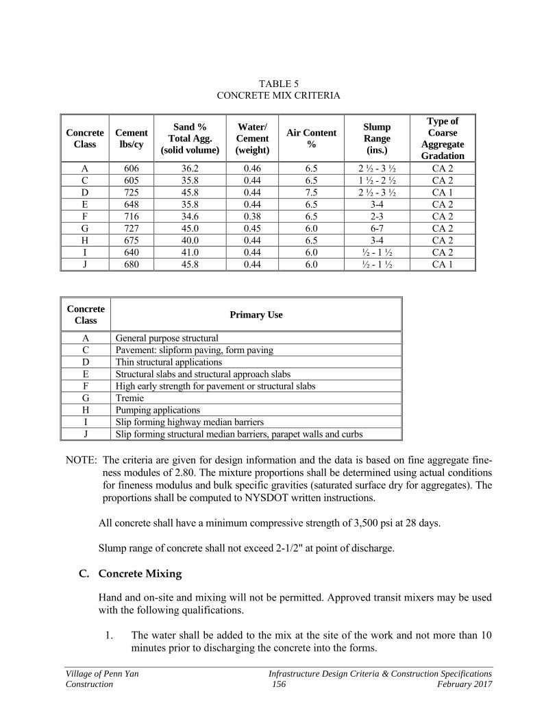
Village of Penn Yan Infrastructure Design Criteria & Construction Specifications
Construction 156 February 2017
TABLE 5
CONCRETE MIX CRITERIA
Concrete
Class
Cement
lbs/cy
Sand %
Total Agg.
(solid volume)
Water/
Cement
(weight)
Air Content
%
Slump
Range
(ins.)
Type of
Coarse
Aggregate
Gradation
A 606 36.2 0.46 6.5 2 ½ - 3 ½ CA 2 C 605 35.8 0.44 6.5 1 ½ - 2 ½ CA 2 D 725 45.8 0.44 7.5 2 ½ - 3 ½ CA 1 E 648 35.8 0.44 6.5 3-4 CA 2 F 716 34.6 0.38 6.5 2-3 CA 2 G 727 45.0 0.45 6.0 6-7 CA 2 H 675 40.0 0.44 6.5 3-4 CA 2 I 640 41.0 0.44 6.0 ½ - 1 ½ CA 2 J 680 45.8 0.44 6.0 ½ - 1 ½ CA 1
Concrete
Class Primary Use
A General purpose structural C Pavement: slipform paving, form paving D Thin structural applications E Structural slabs and structural approach slabs F High early strength for pavement or structural slabs G Tremie H Pumping applications I Slip forming highway median barriers J Slip forming structural median barriers, parapet walls and curbs
NOTE: The criteria are given for design information and the data is based on fine aggregate fine-
ness modules of 2.80. The mixture proportions shall be determined using actual conditions for fineness modulus and bulk specific gravities (saturated surface dry for aggregates). The proportions shall be computed to NYSDOT written instructions.
All concrete shall have a minimum compressive strength of 3,500 psi at 28 days.
Slump range of concrete shall not exceed 2-1/2" at point of discharge.
C. Concrete Mixing
Hand and on-site and mixing will not be permitted. Approved transit mixers may be used with the following qualifications.
1. The water shall be added to the mix at the site of the work and not more than 10
minutes prior to discharging the concrete into the forms.
Village of Penn Yan Infrastructure Design Criteria & Construction Specifications
Construction 157 February 2017
2. Mixing time shall be at least five minutes.
3. Not more than 10 minutes shall elapse between placing of consecutive batches, unless an expansion joint is placed to separate concrete from consecutive batches.
4. Mixers shall be thoroughly cleaned after each batch. They shall not be cleaned in the street or on lawns along the site of the work.
5. The company furnishing the concrete in the transit mixers shall furnish the Vil-lage a letter signed by a responsible official of the company certifying that the materials and proportioning conform to this specification.
6. No re-tempering of concrete shall be permitted.
D. Subgrade Preparation
After preparing the site the contractor shall remove subsoil to the subgrade elevation. A string line shall be placed along the side of the cut in order to maintain proper grade and alignment.
Tree roots shall be neatly cut and trimmed at least 2 inches below and to the side of the "boxed-out" sub-grade.
Contractor bears the responsibility of contacting appropriate water and gas utility companies in order to have curb shut-offs staked out prior to starting the work.
Where fill material is required to meet the proper grade it shall consist of select fill (NYSDOT Item 203.06).
E. Crushed Stone Base
The contractor shall install a washed #l & #2 crushed stone base course (NYSDOT Item 623.12) that has a total compacted thickness of 6 inches. This base course shall be placed under all proposed concrete sidewalks and shall be compacted as approved by the Vil-lage.
F. Form Work And Concrete Placement
Metal or wood forms of a type satisfactory to the Village shall be placed upon the base course. They shall be set true to line and grade. Sufficient form pins and other braces shall be used to prevent movement during concrete placement or finishing. Forms shall have a height equal to the full depth of the walk. A "scratch-plate" shall be employed by the contractor in fine grading to assure full depth of concrete walk. Before placing concrete, the forms and base course shall be thoroughly wetted.
Village of Penn Yan Infrastructure Design Criteria & Construction Specifications
Construction 158 February 2017
Concrete may be placed directly in the forms from the chutes of transit mixers, placing it as neatly as possible to its final position. Concrete shall be thoroughly spaded and worked along both sides of forms in order to get a dense mortar finish along both sides of the walk. Concrete shall be placed to an elevation slightly higher than the top of the forms. It shall be worked with hand shovels in order to obtain a dense, well-consolidated mix. If slip form paving is the preferred method for construction, then concrete shall meet the requirements of NYSDOT Class "C" concrete and sidewalk will be constructed in ac-cordance with the Standard Detail. Slip form pavers shall meet the equipment criteria of NYSDOT 502-2.04.A.
G. Finishing And Curing
After placing and leveling-off the concrete to an elevation slightly higher than the forms it shall be rough screeded with a heavy screed riding on the forms. Excess concrete shall be continually removed from in front of the screed to prevent its raising up. After rough screeding, a second pass shall be made to remove any transverse indentations caused by the rough screeding. Following this the surface shall receive a light broom fin-ish. The broom shall be moist, but not dripping wet. It shall be clean and free of dirt or hardened cement particles which would mark the surface. The sidewalk shall be edged with a proper metal edging tool. Curing shall be accomplished by placing curing paper as soon as concrete is sufficiently hardened. Colorless membrane waterproofing may be substituted if approved by the Vil-lage representative. Curing paper shall be brought down over the edge of the forms and the edges fully buried in earth in order to hold it in place and seal the air space under the paper. Curing shall continue for three days.
H. Joints
Full-depth joints shall be placed as shown on the plans using l/8" steel plate (or an ap-proved equal) for the full depth of the joint. After concrete has sufficiently set-up this plate shall be removed. In addition to the full-depth joints, dummy transverse joints (scor-ing) shall be formed every 5' using a "deep-edge" tool. Both longitudinal edges shall be finished in a similar manner.
I. Convenience of Property Owners
The contractor shall do the following: Provide an access ramp over the walk for each establishment until concrete is sufficiently hardened.
Village of Penn Yan Infrastructure Design Criteria & Construction Specifications
Construction 159 February 2017
J. Testing
Consistency of each mix will be determined by the Village in the field, depending upon the effect provided by the ingredients. At the request of the Village, the Developer will arrange for a qualified testing laboratory to perform on-site slump and air entrapment testing and to obtain cylinders for compression testing. Any batch that does not fall with-in the specified range of slumps shall be rejected by the Village and removed from the site of the work.
K. Batching
All concrete will be batched from a NYSDOT accepted automated plant. Batch plants shall be accompanied with a ticket showing weights of ingredients in loads. The Village is to get a copy of the ticket at time of delivery.
L. Final Trim, Seeding, and Clean-up
After the curing period the contractor shall carefully remove the forms. 16.4 Sediment and Dust Control
A. General
Sediment and erosion control facilities are to be constructed as required in the New York State Department of Environmental Conservation’s SPDES General Permit for Storm-water Discharges from Construction Activity, Permit No. GP-0-15-002. These requirements are as described in the “New York State Stormwater Management Design Manual” and the “New York Guidelines for Urban Erosion Control”. A Stormwater Pol-lution Prevention Plan (SWPPP) meeting these requirements must be prepared and submitted to the Village prior to the Planning Board approval. A Notice of Intent (NOI) meeting the same requirements must be submitted to NYSDEC and the Village prior to the start of construction.
B. Sequence of Work
The construction of sediment interceptor, entrapment, and settling facilities shall be un-dertaken, completed, and approved prior to any other work of a construction nature taking place on the project. No other stripping of vegetation or other ground cover, earth movement, trenching or excavation, shall be commenced until, in the judgment of the Village the sediment control facilities are complete, adequate and operable.
C. Scope of Facilities
The facilities shall consist of sediment interceptor swales, sediment sinks/settling ponds and ancillary features required by the design and subdivision plans approval process, to-gether with such directives as the Village may, from time to time, issue in order to

Village of Penn Yan Infrastructure Design Criteria & Construction Specifications
Construction 160 February 2017
improve performance or to adjust for changes in the Developer's construction sequence or procedures, or to correct for partial or total failure or loss of efficiency of the facilities.
D. Performance
It is the intention to retain on-site all products of erosion caused by disturbance and/or removal of vegetation or other ground cover. The basic concept is to utilize interceptor swales at the base, or downhill limit, of disturbed areas, draining to temporary sediment sinks/settling basins, to which location the storm drain systems shall also temporarily drain until such time as the land development project has been sufficiently restored with ground cover as to prevent soil erosion. Further, the intent is to retain gross soil particles on-site, and to minimize, to the standard permitted by the state-of-the-art, the passage of colloidal particles into the natural waters of the Village. Because of the wide range of partially or totally uncontrollable variables during the land development (the worst return-frequency storm, the area of stripped ground cover, the presence or absence of completed storm drain systems, the amount of sediment stored in the sink at any given time, the variation in soil texture, or the presence of saturated or frozen ground, for example) each sediment sink/entrapment facility shall include a filter fabric barrier to protect the discharge. Performance shall be measured by the ability of the facility to pass all runoff through the filter fabric at all times during construction. It is the responsibility of the Developer adequately to maintain the filtering integrity of the facility and to repair or replace it when required. Degenerating efficiency as evidenced by holes, rips, or tears in the fabric, or failure of the settling pond to drain after a storm because of filter fabric blinding, or the presence of highly turbid water downstream of the fabric, shall be considered cause for repair and or replacement.
E. Ancillary Sediment Control Features
In order to extend the longevity of the sediment sink facility, thereby minimizing the maintenance costs of filter fabric replacement and interim excavation of the sediment sink, the Village encourages the use of ancillary sediment control features throughout the land development project. These suggested methods are encouraged:
1. Minimize the area of stripped ground cover at any one time.
2. Provide hydraulically placed mulch of the "mat" type on raw areas that must be exposed for extended periods.
3. Place firmly anchored and embedded straw bales or filter fabric barriers in areas of concentrated run-off, such as at culvert and catch basin inlets, and in swales, in an effort to reduce soil transport reaching the settling pond.
Village of Penn Yan Infrastructure Design Criteria & Construction Specifications
Construction 161 February 2017
4. Wherever possible, leave temporary buffer strips of original ground cover vegeta-tion to act as soil migration retardant.
5. Use "Soil Saver" jute mush along swales or other areas where runoff rates are of sufficient quantity or velocity as to cause additional erosion.
6. Restore ground surface protection as soon as possible by utilizing hydraulically-placed mulch of the "mat" type.
F. Termination of Facilities
The judgment as to the appropriate time of termination of facilities rests with the Village, whose decision shall be final and binding.
The primary performance criteria used in making the determination will be the quality of the runoff from the development entering the sediment settling facility. When, in the judgment of the Village, the ground cover in the land development project has been suffi-ciently restored such that runoff through the swales and storm drain system is relatively soil-free, permission may be granted to divert flow through the permanent storm water detention pond or such other drainage systems as are described on the approved plans.
The Developer and his engineer are reminded that dependence on siltation facilities from one construction season to the next greatly increases the statistical possibility of storms of greater intensity, resulting in greater runoff and erosion with subsequent possible overtax-ing or failure of the facility. Therefore, expeditious restoration of ground cover, or temporary protection of soil surface is strongly encouraged.
G. Dust and Mud Control
Recognizing that removal of vegetation, dry conditions, and periodic high winds cause nuisance dust movement the Developer shall take such steps as are necessary to avoid nuisance and damage to abutting properties and occupants Such steps may include, but not be limited to, wetting-down exposed soil areas, mulching, and re-vegetating disturbed areas. Further, the Developer is responsible for minimizing "tracking" of mud onto existing roads. Roads shall be scraped and broomed clear of mud at the end of each working day as required. The Village reserves the right to include in the letter of credit an allowance to cover the estimated cost of such dust-and-mud control. A stabilized construction entrance will be required to reduce the tracking of sediment on-to public rights-of-way or streets. If necessary, wheels may be washed to remove sediment when a sediment basin and proper drainage is provided.
Village of Penn Yan Infrastructure Design Criteria & Construction Specifications
Construction 162 February 2017
THIS PAGE INTENTIONALLY BLANK

Appendices

THIS PAGE INTENTIONALLY BLANK

Appendix A
Irrevocable Letter of Credit

THIS PAGE INTENTIONALLY BLANK
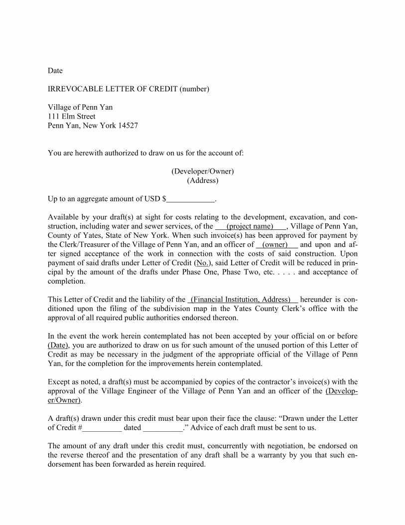
Date IRREVOCABLE LETTER OF CREDIT (number) Village of Penn Yan 111 Elm Street Penn Yan, New York 14527 You are herewith authorized to draw on us for the account of:
(Developer/Owner) (Address)
Up to an aggregate amount of USD $ . Available by your draft(s) at sight for costs relating to the development, excavation, and con-struction, including water and sewer services, of the (project name) , Village of Penn Yan, County of Yates, State of New York. When such invoice(s) has been approved for payment by the Clerk/Treasurer of the Village of Penn Yan, and an officer of (owner) and upon and af-ter signed acceptance of the work in connection with the costs of said construction. Upon payment of said drafts under Letter of Credit (No.), said Letter of Credit will be reduced in prin-cipal by the amount of the drafts under Phase One, Phase Two, etc. . . . . and acceptance of completion. This Letter of Credit and the liability of the (Financial Institution, Address) hereunder is con-ditioned upon the filing of the subdivision map in the Yates County Clerk’s office with the approval of all required public authorities endorsed thereon. In the event the work herein contemplated has not been accepted by your official on or before (Date), you are authorized to draw on us for such amount of the unused portion of this Letter of Credit as may be necessary in the judgment of the appropriate official of the Village of Penn Yan, for the completion for the improvements herein contemplated. Except as noted, a draft(s) must be accompanied by copies of the contractor’s invoice(s) with the approval of the Village Engineer of the Village of Penn Yan and an officer of the (Develop-er/Owner). A draft(s) drawn under this credit must bear upon their face the clause: “Drawn under the Letter of Credit #__________ dated __________.” Advice of each draft must be sent to us. The amount of any draft under this credit must, concurrently with negotiation, be endorsed on the reverse thereof and the presentation of any draft shall be a warranty by you that such en-dorsement has been forwarded as herein required.
This credit must accompany any draft which exhausts this credit and must be surrendered con-currently with the payment of such draft. We hereby agree with the drawers, endorsers, and bonafide holders of drafts drawn and negotiat-ed under and in compliance with the terms of the credit that they shall be duly honored on due presentation to us. This Letter of Credit is subject to the Uniform Customs and Practice for Documentary Credits (2007 Revision) International Chamber of Commerce Publication No. 600. Very truly yours, (Financial Institution)
Appendix B
Engineer’s Estimate of Probable Cost
for Letter of Credit

THIS PAGE INTENTIONALLY BLANK
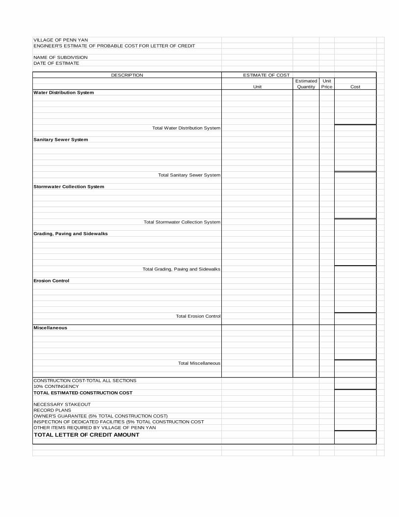
VILLAGE OF PENN YAN
ENGINEER'S ESTIMATE OF PROBABLE COST FOR LETTER OF CREDIT
NAME OF SUBDIVISION
DATE OF ESTIMATE
DESCRIPTION ESTIMATE OF COST
Estimated Unit
Unit Quantity Price Cost
Water Distribution System
Total Water Distribution System
Sanitary Sewer System
Total Sanitary Sewer System
Stormwater Collection System
Total Stormwater Collection System
Grading, Paving and Sidewalks
Total Grading, Paving and Sidewalks
Erosion Control
Total Erosion Control
Miscellaneous
Total Miscellaneous
CONSTRUCTION COST-TOTAL ALL SECTIONS
10% CONTINGENCY
TOTAL ESTIMATED CONSTRUCTION COST
NECESSARY STAKEOUT
RECORD PLANS
OWNER'S GUARANTEE (5% TOTAL CONSTRUCTION COST)
INSPECTION OF DEDICATED FACILITIES (5% TOTAL CONSTRUCTION COST
OTHER ITEMS REQUIRED BY VILLAGE OF PENN YAN
TOTAL LETTER OF CREDIT AMOUNT

THIS PAGE INTENTIONALLY BLANK
Appendix C
Sample Statement of
Completed Construction

THIS PAGE INTENTIONALLY BLANK
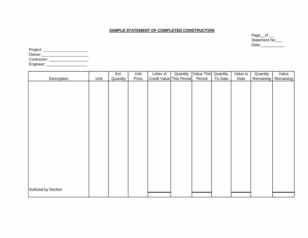
SAMPLE STATEMENT OF COMPLETED CONSTRUCTION
Page__of __
Statement No,___
Date:___________
Project: _____________________
Owner:______________________
Contractor: __________________
Engineer: ___________________
Est. Unit Letter of Quantity Value This Quantity Value to Quantity Value
Description Unit Quantity Price Credit Value This Period Period To Date Date Remaining Remaining
Subtotal by Section

THIS PAGE INTENTIONALLY BLANK
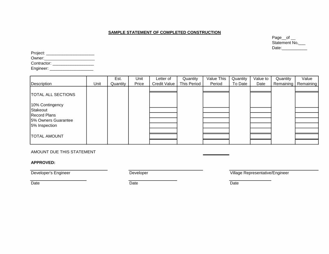
SAMPLE STATEMENT OF COMPLETED CONSTRUCTION
Page__of __
Statement No,___
Date:___________
Project: _____________________
Owner:______________________
Contractor: __________________
Engineer: ___________________
Est. Unit Letter of Quantity Value This Quantity Value to Quantity Value
Description Unit Quantity Price Credit Value This Period Period To Date Date Remaining Remaining
TOTAL ALL SECTIONS
10% Contingency
Stakeout
Record Plans
5% Owners Guarantee
5% Inspection
TOTAL AMOUNT
AMOUNT DUE THIS STATEMENT
APPROVED:
Developer's Engineer Developer Village Representative/Engineer
Date Date Date

THIS PAGE INTENTIONALLY BLANK

Standard Details

THIS PAGE INTENTIONALLY BLANK

ABOVESEWER LINE
WATER LINEABOVESEWER LINE
SL
WL
MORE THAN12 INCHES
SL
WATER LINE-SEWER LINE CROSSING PROVISIONSREQUIREMENTSSITUATION SCHEMATIC
WL
18 INCHES,
SL
MORE THAN 12 INCHES
WL
WATER LINEABOVESEWER LINE
WATER LINEB)
A)
CROSSING, WHEN POSSIBLE.ONE FULL LENGTH CONTERED AT
LINE ARE NEW, SLEEVE SEWER LINE WITHWHEN BOTH WATER LINE AND SEWER
WATER LINE AND SEWER LINE SHALL BE
STEEL CASING FOR FULL LENGTH OF PIPEAT CROSSING.
WHEN ONE LINE IS EXISTING, SLEEVE
CASING FOR ONE FULL LENGTH OF PIPE.PIPE BEING INSTALLED WITH STEEL
WATER LINE AND SEWER LINE SHALL BEONE FULL LENGTH CENTERED ATCROSSING, WHEN POSSIBLE.SLEEVE SEWER LINE WITH STEEL CASINGFOR ENTIRE LENGTH OF PIPE (EACH SIDEOF CROSSING).PROVIDE CRADLE OF CONCRETE OR
B)
A)
C)CRUSHER RUN STONE (SEE TRENCHSECTION DETAIL THIS SHEET) FORWATER LINE AND SEWER LINE FORENTIRE LENGTH OF PIPE EACH SIDE OFCROSSING.
--OR--
MINIMUM
BUT LESS THAN18 INCHES
DATE: JANUARY 2017
VILLAGE OF PENN YAN
Dra
win
g N
ame:
J:\
PRO
JEC
TS\P
enn
Yan_
V\C
omp
Plan
\F G
ener
al E
ngin
eerin
g\D
esig
n St
and
ard
s\M
aste
r Dra
win
gs\M
ISC
ELLA
NEO
US\M
iscel
lane
ous D
etai
ls.d
wg
Dat
e la
st a
cces
sed
: 2/2
0/20
17 1
:16
PMD
ate
last
plo
tted
: 2/2
0/20
17 2
:13
PMPl
otte
d B
y: M
aure
en N
alew
alsk
i
SCALE: N.T.S. DRAWING M-01
MISCELLANEOUS DETAILS
SANITARY SEWER& WATER MAIN
CROSSING
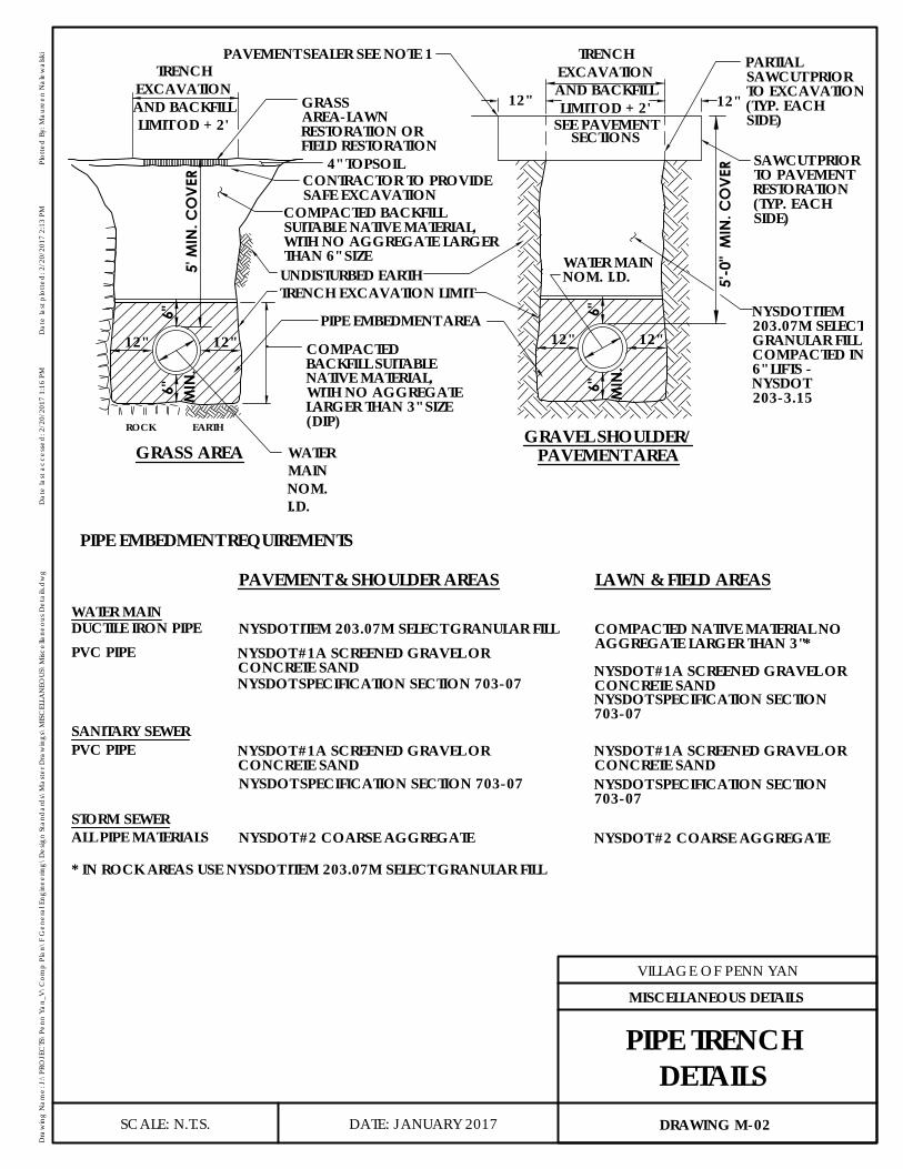
ROCK
5' M
IN. C
OVE
R
EARTH
6" MIN
.
5'-0
" M
IN. C
OVE
R
SEE PAVEMENTSECTIONS
12"12"
6"
GRASS AREA PAVEMENT AREA
12" 12"
GRAVEL SHOULDER/
PAVEMENT & SHOULDER AREAS LAWN & FIELD AREAS
PIPE EMBEDMENT REQUIREMENTS
DUCTILE IRON PIPEPVC PIPE
SANITARY SEWERPVC PIPE
STORM SEWERALL PIPE MATERIALS
NYSDOT ITEM 203.07M SELECT GRANULAR FILL
NYSDOT SPECIFICATION SECTION 703-07
NYSDOT #2 COARSE AGGREGATE
* IN ROCK AREAS USE NYSDOT ITEM 203.07M SELECT GRANULAR FILL
WATER MAIN
6"M
IN.
12"
6"
12"
TRENCHEXCAVATIONAND BACKFILLLIMIT OD + 2'
GRASSAREA-LAWNRESTORATION ORFIELD RESTORATION
4" TOPSOILCONTRACTOR TO PROVIDESAFE EXCAVATION
COMPACTED BACKFILLSUITABLE NATIVE MATERIAL,WITH NO AGGREGATE LARGERTHAN 6" SIZEUNDISTURBED EARTHTRENCH EXCAVATION LIMIT
COMPACTEDBACKFILL SUITABLENATIVE MATERIAL,WITH NO AGGREGATELARGER THAN 3" SIZE(DIP)
WATERMAINNOM.I.D.
PIPE EMBEDMENT AREA
PAVEMENT SEALER SEE NOTE 1 TRENCHEXCAVATIONAND BACKFILLLIMIT OD + 2'
PARTIALSAWCUT PRIORTO EXCAVATION(TYP. EACHSIDE)
SAWCUT PRIORTO PAVEMENTRESTORATION(TYP. EACHSIDE)
NYSDOT ITEM203.07M SELECTGRANULAR FILLCOMPACTED IN6" LIFTS -NYSDOT203-3.15
WATER MAINNOM. I.D.
NYSDOT #2 COARSE AGGREGATE
NYSDOT #1A SCREENED GRAVEL ORCONCRETE SAND
NYSDOT #1A SCREENED GRAVEL ORCONCRETE SANDNYSDOT SPECIFICATION SECTION703-07
NYSDOT #1A SCREENED GRAVEL ORCONCRETE SANDNYSDOT SPECIFICATION SECTION 703-07
COMPACTED NATIVE MATERIAL NOAGGREGATE LARGER THAN 3"*
NYSDOT #1A SCREENED GRAVEL ORCONCRETE SANDNYSDOT SPECIFICATION SECTION703-07
DATE: JANUARY 2017
VILLAGE OF PENN YAN
Dra
win
g N
ame:
J:\
PRO
JEC
TS\P
enn
Yan_
V\C
omp
Plan
\F G
ener
al E
ngin
eerin
g\D
esig
n St
and
ard
s\M
aste
r Dra
win
gs\M
ISC
ELLA
NEO
US\M
iscel
lane
ous D
etai
ls.d
wg
Dat
e la
st a
cces
sed
: 2/2
0/20
17 1
:16
PMD
ate
last
plo
tted
: 2/2
0/20
17 2
:13
PMPl
otte
d B
y: M
aure
en N
alew
alsk
i
SCALE: N.T.S. DRAWING M-02
MISCELLANEOUS DETAILS
PIPE TRENCHDETAILS
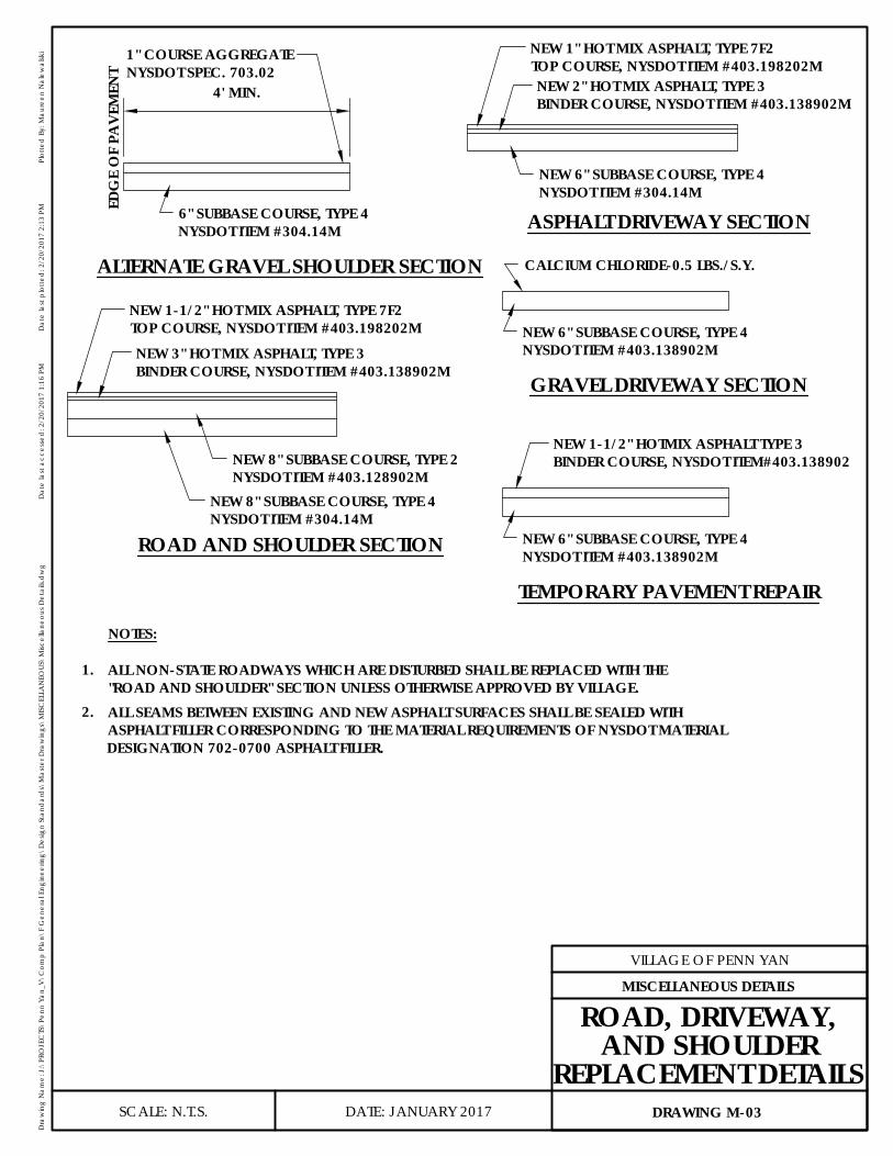
ASPHALT DRIVEWAY SECTION
GRAVEL DRIVEWAY SECTION
ROAD AND SHOULDER SECTION
NOTES:
1.
2.
TEMPORARY PAVEMENT REPAIR
ALTERNATE GRAVEL SHOULDER SECTION
4' MIN.
NEW 1" HOT MIX ASPHALT, TYPE 7F2TOP COURSE, NYSDOT ITEM #403.198202MNEW 2" HOT MIX ASPHALT, TYPE 3BINDER COURSE, NYSDOT ITEM #403.138902M
1" COURSE AGGREGATENYSDOT SPEC. 703.02
EDG
E O
F PA
VEM
ENT
6" SUBBASE COURSE, TYPE 4NYSDOT ITEM #304.14M
NEW 1-1/2" HOT MIX ASPHALT, TYPE 7F2TOP COURSE, NYSDOT ITEM #403.198202MNEW 3" HOT MIX ASPHALT, TYPE 3BINDER COURSE, NYSDOT ITEM #403.138902M
NEW 8" SUBBASE COURSE, TYPE 2NYSDOT ITEM #403.128902M
NEW 8" SUBBASE COURSE, TYPE 4NYSDOT ITEM #304.14M
ALL NON-STATE ROADWAYS WHICH ARE DISTURBED SHALL BE REPLACED WITH THE"ROAD AND SHOULDER" SECTION UNLESS OTHERWISE APPROVED BY VILLAGE.ALL SEAMS BETWEEN EXISTING AND NEW ASPHALT SURFACES SHALL BE SEALED WITHASPHALT FILLER CORRESPONDING TO THE MATERIAL REQUIREMENTS OF NYSDOT MATERIALDESIGNATION 702-0700 ASPHALT FILLER.
NEW 6" SUBBASE COURSE, TYPE 4NYSDOT ITEM #403.138902M
NEW 1-1/2" HOTMIX ASPHALT TYPE 3BINDER COURSE, NYSDOT ITEM#403.138902
NEW 6" SUBBASE COURSE, TYPE 4NYSDOT ITEM #403.138902M
CALCIUM CHLORIDE-0.5 LBS./S.Y.
NEW 6" SUBBASE COURSE, TYPE 4NYSDOT ITEM #304.14M
DATE: JANUARY 2017
VILLAGE OF PENN YAN
Dra
win
g N
ame:
J:\
PRO
JEC
TS\P
enn
Yan_
V\C
omp
Plan
\F G
ener
al E
ngin
eerin
g\D
esig
n St
and
ard
s\M
aste
r Dra
win
gs\M
ISC
ELLA
NEO
US\M
iscel
lane
ous D
etai
ls.d
wg
Dat
e la
st a
cces
sed
: 2/2
0/20
17 1
:16
PMD
ate
last
plo
tted
: 2/2
0/20
17 2
:13
PMPl
otte
d B
y: M
aure
en N
alew
alsk
i
SCALE: N.T.S. DRAWING M-03
MISCELLANEOUS DETAILS
ROAD, DRIVEWAY,AND SHOULDER
REPLACEMENT DETAILS

1'-0' MIN.
MULCH
2'-6
" MIN
.
1. REMOVE STAKES, WIRE & HOSE AT THE END OF THE ONE YEAR MAINTENANCE AND GUARANTY PERIOD.
NOTES:
BALL DIA. 2'+
1'-0' MIN.
3"
3"
PRUNE, THIN OUT ANDSHAPE TREES ASDIRECTED BY NYSDOTITEM 611.01M
#14 GA. GALVANIZEDWIRE, LOCATE SO ITWON'T PULL CROTCHAPART
MIN. 3 HARDWOODSTAKES, PER TREE -2"x2"x6'
BUILD SAUCER OUTSIDEPLANT PIT AS SHOWNTO BE REMOVEDBEFORE WINTER
AMENDEDBACKFILL; 1 PARTPEAT MOSS TO 3PARTS TOPSOIL
TREE PITS NOT TO BEEXCAVATED UNTILTIME OF PLANTING.
RAISE BASE OF PITAT CENTER
SURFACE OF PLANTINGPIT & RIM OF SAUCERTO BE LEVEL TO HOLDA UNIFORM DEPTH OFWATER
CUT AWAY BURLAP FROMUPPER 1/2 OF ROOT BALL
TREE WRAP
RUBBER HOSE
DATE: JANUARY 2017
VILLAGE OF PENN YAN
Dra
win
g N
ame:
J:\
PRO
JEC
TS\P
enn
Yan_
V\C
omp
Plan
\F G
ener
al E
ngin
eerin
g\D
esig
n St
and
ard
s\M
aste
r Dra
win
gs\M
ISC
ELLA
NEO
US\M
iscel
lane
ous D
etai
ls.d
wg
Dat
e la
st a
cces
sed
: 2/2
0/20
17 1
:16
PMD
ate
last
plo
tted
: 2/2
0/20
17 2
:13
PMPl
otte
d B
y: M
aure
en N
alew
alsk
i
SCALE: N.T.S. DRAWING M-04
MISCELLANEOUS DETAILS
TREE PLANTING
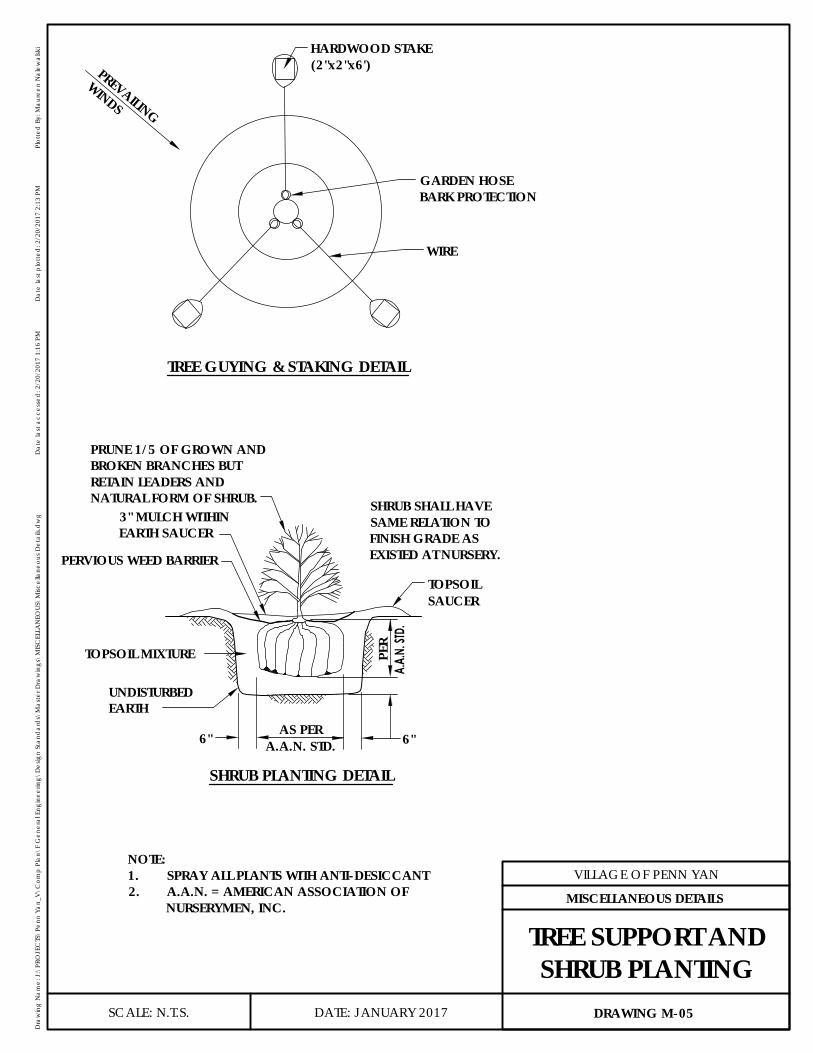
WIRE
WINDS
PREVAILING
TREE GUYING & STAKING DETAIL
SHRUB PLANTING DETAIL
6"6"
PER
A.A.
N. ST
D.
AS PERA.A.N. STD.
TOPSOILSAUCER
HARDWOOD STAKE(2"x2"x6')
GARDEN HOSEBARK PROTECTION
PRUNE 1/5 OF GROWN ANDBROKEN BRANCHES BUTRETAIN LEADERS ANDNATURAL FORM OF SHRUB.
3" MULCH WITHINEARTH SAUCER
PERVIOUS WEED BARRIER
TOPSOIL MIXTURE
UNDISTURBEDEARTH
SHRUB SHALL HAVESAME RELATION TOFINISH GRADE ASEXISTED AT NURSERY.
NOTE:1. SPRAY ALL PLANTS WITH ANTI-DESICCANT2. A.A.N. = AMERICAN ASSOCIATION OF
NURSERYMEN, INC.
DATE: JANUARY 2017
VILLAGE OF PENN YAN
Dra
win
g N
ame:
J:\
PRO
JEC
TS\P
enn
Yan_
V\C
omp
Plan
\F G
ener
al E
ngin
eerin
g\D
esig
n St
and
ard
s\M
aste
r Dra
win
gs\M
ISC
ELLA
NEO
US\M
iscel
lane
ous D
etai
ls.d
wg
Dat
e la
st a
cces
sed
: 2/2
0/20
17 1
:16
PMD
ate
last
plo
tted
: 2/2
0/20
17 2
:13
PMPl
otte
d B
y: M
aure
en N
alew
alsk
i
SCALE: N.T.S. DRAWING M-05
MISCELLANEOUS DETAILS
TREE SUPPORT ANDSHRUB PLANTING
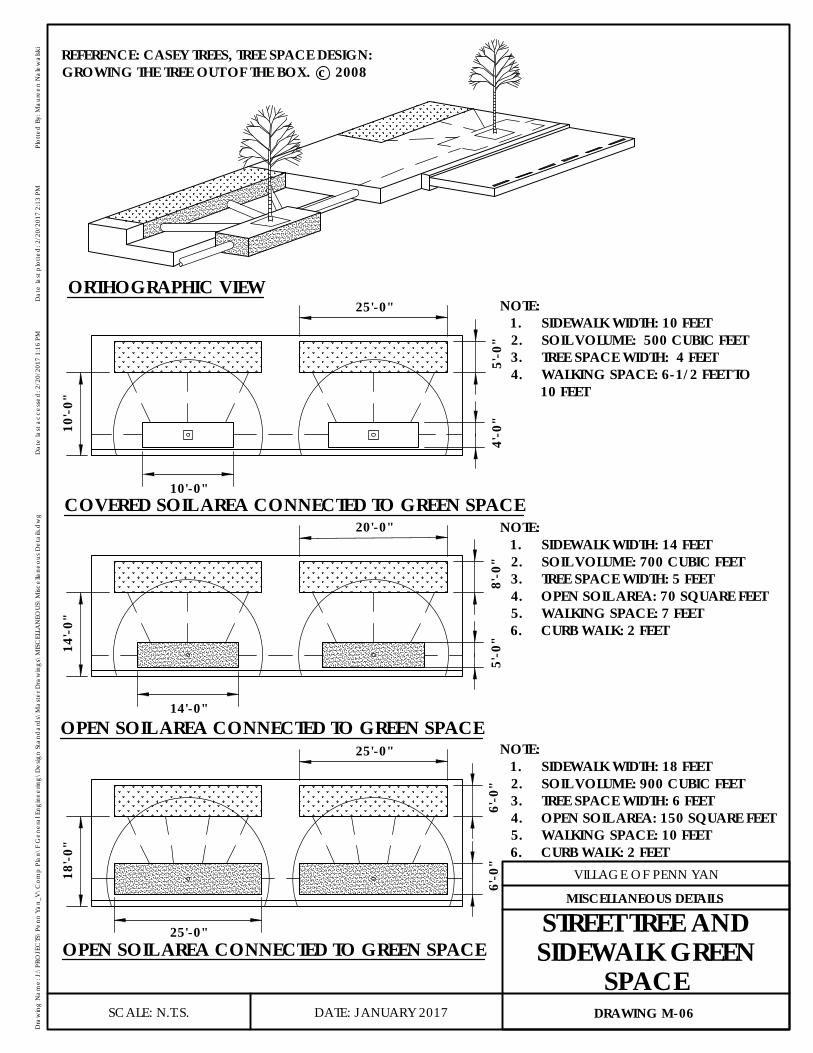
10'-0
"
4'-0
"5'
-0"
10'-0"
25'-0"ORTHOGRAPHIC VIEW
COVERED SOIL AREA CONNECTED TO GREEN SPACE
NOTE:1. SIDEWALK WIDTH: 10 FEET2. SOIL VOLUME: 500 CUBIC FEET3. TREE SPACE WIDTH: 4 FEET4. WALKING SPACE: 6-1/2 FEET TO
10 FEET
14'-0
"
5'-0
"8'
-0"
14'-0"
20'-0" NOTE:1. SIDEWALK WIDTH: 14 FEET2. SOIL VOLUME: 700 CUBIC FEET3. TREE SPACE WIDTH: 5 FEET4. OPEN SOIL AREA: 70 SQUARE FEET5. WALKING SPACE: 7 FEET6. CURB WALK: 2 FEET
OPEN SOIL AREA CONNECTED TO GREEN SPACE
18'-0
"
25'-0"
25'-0" NOTE:1. SIDEWALK WIDTH: 18 FEET2. SOIL VOLUME: 900 CUBIC FEET3. TREE SPACE WIDTH: 6 FEET4. OPEN SOIL AREA: 150 SQUARE FEET5. WALKING SPACE: 10 FEET6. CURB WALK: 2 FEET
OPEN SOIL AREA CONNECTED TO GREEN SPACE
6'-0
"6'
-0"
REFERENCE: CASEY TREES, TREE SPACE DESIGN:GROWING THE TREE OUT OF THE BOX. c 2008
DATE: JANUARY 2017
VILLAGE OF PENN YAN
Dra
win
g N
ame:
J:\
PRO
JEC
TS\P
enn
Yan_
V\C
omp
Plan
\F G
ener
al E
ngin
eerin
g\D
esig
n St
and
ard
s\M
aste
r Dra
win
gs\M
ISC
ELLA
NEO
US\M
iscel
lane
ous D
etai
ls.d
wg
Dat
e la
st a
cces
sed
: 2/2
0/20
17 1
:16
PMD
ate
last
plo
tted
: 2/2
0/20
17 2
:13
PMPl
otte
d B
y: M
aure
en N
alew
alsk
i
SCALE: N.T.S. DRAWING M-06
MISCELLANEOUS DETAILS
STREET TREE ANDSIDEWALK GREEN
SPACE

1.
(COMPRESSIVE STRENGTH: 50-100 PSI)CONTROLLED LOW STRENGTH MATERIALFILL VOID WITH NYSDOT ITEM #204.02
NOTES: WALL THICKNESS)
STAINLESS CLAMPS
CASING SPACERS (3 PER
L/6L/3L/3L/6
L
CASING SPACERS
-POLYMER RUNNERS -STAINLESS STEEL BOLTS -PVC LINERS
-14 GAUGE T304LENGTH) WITH THE FOLLOWING:
CARRIER PIPE
STEEL CASING (0.375" MIN.
STEEL CASING PIPE
CARRIER PIPE
DATE: JANUARY 2017
VILLAGE OF PENN YAN
Dra
win
g N
ame:
J:\
PRO
JEC
TS\P
enn
Yan_
V\C
omp
Plan
\F G
ener
al E
ngin
eerin
g\D
esig
n St
and
ard
s\M
aste
r Dra
win
gs\M
ISC
ELLA
NEO
US\M
iscel
lane
ous D
etai
ls.d
wg
Dat
e la
st a
cces
sed
: 2/2
0/20
17 1
:16
PMD
ate
last
plo
tted
: 2/2
0/20
17 2
:13
PMPl
otte
d B
y: M
aure
en N
alew
alsk
i
SCALE: N.T.S. DRAWING M-07
MISCELLANEOUS DETAILS
TYPICAL STEELCASING PIPE

(0.375" MIN.
DEWATERINGWELDING &SUMP PIT FOR
6" 50-50 BLEND NYSDOT
BLOCKTHRUST
CASING PIPE
1'-6"
12" BERM
12" BERM
#1 & #2 COARSE AGGREGATE
WALL THICKNESS)
NOTE:1. SHEETING IF NECESSARY, WILL BE AS REQUIRED BY N.Y.S.D.O.T.
COUNTY, OR ANY LOCAL STATE, OR FEDERAL REGULATIONS.2. 12" EARTH BERM TO BE PLACED AROUND SHEETING.
DATE: JANUARY 2017
VILLAGE OF PENN YAN
Dra
win
g N
ame:
J:\
PRO
JEC
TS\P
enn
Yan_
V\C
omp
Plan
\F G
ener
al E
ngin
eerin
g\D
esig
n St
and
ard
s\M
aste
r Dra
win
gs\M
ISC
ELLA
NEO
US\M
iscel
lane
ous D
etai
ls.d
wg
Dat
e la
st a
cces
sed
: 2/2
0/20
17 1
:16
PMD
ate
last
plo
tted
: 2/2
0/20
17 2
:13
PMPl
otte
d B
y: M
aure
en N
alew
alsk
i
SCALE: N.T.S. DRAWING M-08
MISCELLANEOUS DETAILS
TYPICALBORING PIT
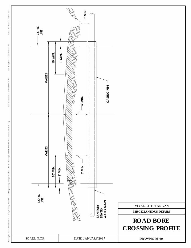
5' M
IN.
1' M
IN.
LIN
ER.
O.W
.
10' M
IN.
CA
SIN
G P
IPE
5' M
IN.
VARI
ES
1' M
IN.
VARI
ES
10' M
IN.
3' M
IN.
LIN
ER.
O.W
.
SAN
ITARY
SEW
ER/
WA
TER
MA
IN
DATE: JANUARY 2017
VILLAGE OF PENN YAN
Dra
win
g N
ame:
J:\
PRO
JEC
TS\P
enn
Yan_
V\C
omp
Plan
\F G
ener
al E
ngin
eerin
g\D
esig
n St
and
ard
s\M
aste
r Dra
win
gs\M
ISC
ELLA
NEO
US\M
iscel
lane
ous D
etai
ls.d
wg
Dat
e la
st a
cces
sed
: 2/2
0/20
17 1
:16
PMD
ate
last
plo
tted
: 2/2
0/20
17 2
:13
PMPl
otte
d B
y: M
aure
en N
alew
alsk
i
SCALE: N.T.S. DRAWING M-09
MISCELLANEOUS DETAILS
ROAD BORECROSSING PROFILE
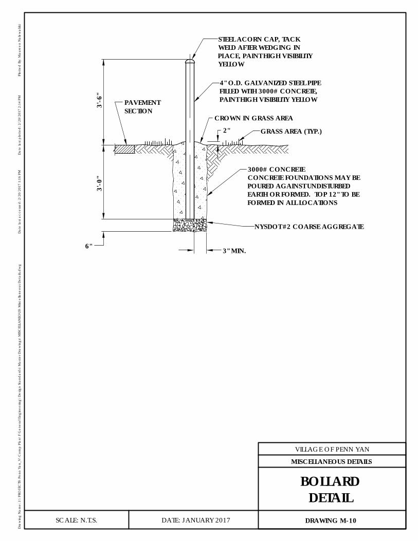
SECTIONPAVEMENT
2"
3'-6
"3'
-0"
6" 3" MIN.
STEEL ACORN CAP, TACKWELD AFTER WEDGING INPLACE, PAINT HIGH VISIBILITYYELLOW
4" O.D. GALVANIZED STEEL PIPEFILLED WITH 3000# CONCRETE,PAINT HIGH VISIBILITY YELLOW
CROWN IN GRASS AREA
GRASS AREA (TYP.)
3000# CONCRETECONCRETE FOUNDATIONS MAY BEPOURED AGAINST UNDISTURBEDEARTH OR FORMED. TOP 12" TO BEFORMED IN ALL LOCATIONS
NYSDOT #2 COARSE AGGREGATE
DATE: JANUARY 2017
VILLAGE OF PENN YAN
Dra
win
g N
ame:
J:\
PRO
JEC
TS\P
enn
Yan_
V\C
omp
Plan
\F G
ener
al E
ngin
eerin
g\D
esig
n St
and
ard
s\M
aste
r Dra
win
gs\M
ISC
ELLA
NEO
US\M
iscel
lane
ous D
etai
ls.d
wg
Dat
e la
st a
cces
sed
: 2/2
0/20
17 1
:16
PMD
ate
last
plo
tted
: 2/2
0/20
17 2
:14
PMPl
otte
d B
y: M
aure
en N
alew
alsk
i
SCALE: N.T.S. DRAWING M-10
MISCELLANEOUS DETAILS
BOLLARDDETAIL
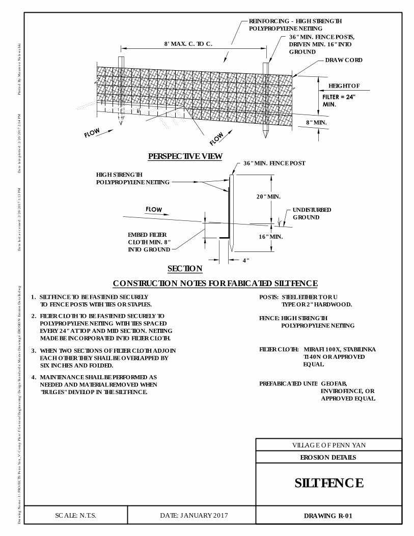
CONSTRUCTION NOTES FOR FABICATED SILT FENCE
8' MAX. C. TO C.
PERSPECTIVE VIEW
FLOW
FLOW
HEIGHT OF
8" MIN.
20" MIN.
36" MIN. FENCE POST
16" MIN.
FLOW
SECTION4"
DRAW CORD
REINFORCING - HIGH STRENGTHPOLYPROPYLENE NETTING
36" MIN. FENCE POSTS,DRIVEN MIN. 16" INTOGROUND
FILTER = 24"MIN.
UNDISTURBEDGROUND
HIGH STRENGTHPOLYPROPYLENE NETTING
EMBED FILTERCLOTH MIN. 8"INTO GROUND
1. SILT FENCE TO BE FASTENED SECURELYTO FENCE POSTS WITH TIES OR STAPLES.
2. FILTER CLOTH TO BE FASTENED SECURELY TOPOLYPROPYLENE NETTING WITH TIES SPACEDEVERY 24" AT TOP AND MID SECTION. NETTINGMADE BE INCORPORATED INTO FILTER CLOTH.
3. WHEN TWO SECTIONS OF FILTER CLOTH ADJOINEACH OTHER THEY SHALL BE OVERLAPPED BYSIX INCHES AND FOLDED.
4. MAINTENANCE SHALL BE PERFORMED ASNEEDED AND MATERIAL REMOVED WHEN"BULGES" DEVELOP IN THE SILT FENCE.
POSTS: STEEL EITHER T OR UTYPE OR 2" HARDWOOD.
FENCE: HIGH STRENGTHPOLYPROPYLENE NETTING
FILTER CLOTH: MIRAFI 100X, STABILINKAT140N OR APPROVEDEQUAL.
PREFABICATED UNIT: GEOFAB,ENVIROFENCE, ORAPPROVED EQUAL.
DATE: JANUARY 2017
VILLAGE OF PENN YAN
Dra
win
g N
ame:
J:\
PRO
JEC
TS\P
enn
Yan_
V\C
omp
Plan
\F G
ener
al E
ngin
eerin
g\D
esig
n St
and
ard
s\M
aste
r Dra
win
gs\E
ROSI
ON
\Ero
sion
Det
ails.
dw
gD
ate
last
acc
esse
d: 2
/20/
2017
1:1
3 PM
Dat
e la
st p
lotte
d: 2
/20/
2017
2:1
4 PM
Plot
ted
By:
Mau
reen
Nal
ewal
ski
SCALE: N.T.S. DRAWING R-01
EROSION DETAILS
SILT FENCE
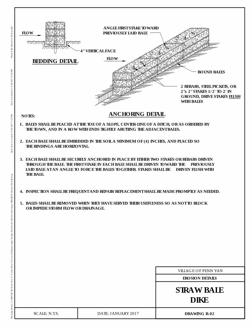
FLOW
BEDDING DETAIL
ANCHORING DETAIL
4" VERTICAL FACE
BOUND BALES
FLOW
NOTES:
2 REBARS, STEEL PICKETS, OR2"x 2" STAKES 1/2' TO 2' INGROUND, DRIVE STAKES FLUSHWITH BALES
ANGLE FIRST STAKE TOWARDPREVIOUSLY LAID BALE
1. BALES SHALL BE PLACED AT THE TOE OF A SLOPE, CENTER-LINE OF A DITCH, OR AS ORDERED BYTHE TOWN, AND IN A ROW WITH ENDS TIGHTLY ABUTTING THE ADJACENT BALES.
2. EACH BALE SHALL BE EMBEDDED IN THE SOIL A MINIMUM OF (4) INCHES, AND PLACED SOTHE BINDINGS ARE HORIZONTAL.
3. EACH BALE SHALL BE SECURELY ANCHORED IN PLACE BY EITHER TWO STAKES OR REBARS DRIVENTHROUGH THE BALE. THE FIRST STAKE IN EACH BALE SHALL BE DRIVEN TOWARD THE PREVIOUSLYLAID BALE AT AN ANGLE TO FORCE THE BALES TOGETHER. STAKES SHALL BE DRIVEN FLUSH WITHTHE BALE.
4. INSPECTION SHALL BE FREQUENT AND REPAIR/REPLACEMENT SHALL BE MADE PROMPTLY AS NEEDED.
5. BALES SHALL BE REMOVED WHEN THEY HAVE SERVED THEIR USEFULNESS SO AS NOT TO BLOCKOR IMPEDE STORM FLOW OR DRAINAGE.
DATE: JANUARY 2017
VILLAGE OF PENN YAN
Dra
win
g N
ame:
J:\
PRO
JEC
TS\P
enn
Yan_
V\C
omp
Plan
\F G
ener
al E
ngin
eerin
g\D
esig
n St
and
ard
s\M
aste
r Dra
win
gs\E
ROSI
ON
\Ero
sion
Det
ails.
dw
gD
ate
last
acc
esse
d: 2
/20/
2017
1:1
3 PM
Dat
e la
st p
lotte
d: 2
/20/
2017
2:1
4 PM
Plot
ted
By:
Mau
reen
Nal
ewal
ski
SCALE: N.T.S. DRAWING R-02
EROSION DETAILS
STRAW BALEDIKE
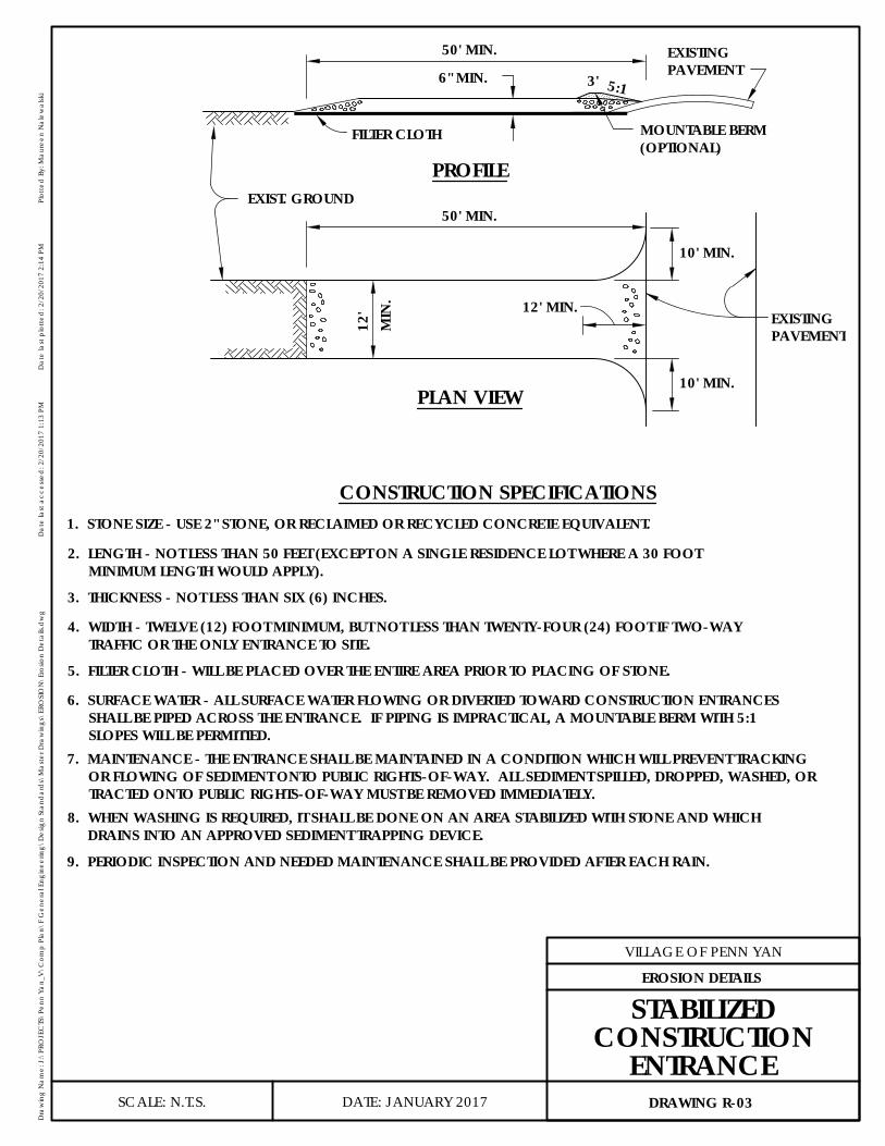
EXIST. GROUND
FILTER CLOTH
50' MIN.
12'
MIN
. 12' MIN.
50' MIN.
10' MIN.
10' MIN.
6" MIN. 3' 5:1
PROFILE
PLAN VIEW
CONSTRUCTION SPECIFICATIONS
EXISTINGPAVEMENT
MOUNTABLE BERM(OPTIONAL)
EXISTINGPAVEMENT
1. STONE SIZE - USE 2" STONE, OR RECLAIMED OR RECYCLED CONCRETE EQUIVALENT.
2. LENGTH - NOT LESS THAN 50 FEET (EXCEPT ON A SINGLE RESIDENCE LOT WHERE A 30 FOOTMINIMUM LENGTH WOULD APPLY).
3. THICKNESS - NOT LESS THAN SIX (6) INCHES.
4. WIDTH - TWELVE (12) FOOT MINIMUM, BUT NOT LESS THAN TWENTY-FOUR (24) FOOT IF TWO-WAYTRAFFIC OR THE ONLY ENTRANCE TO SITE.
5. FILTER CLOTH - WILL BE PLACED OVER THE ENTIRE AREA PRIOR TO PLACING OF STONE.
6. SURFACE WATER - ALL SURFACE WATER FLOWING OR DIVERTED TOWARD CONSTRUCTION ENTRANCESSHALL BE PIPED ACROSS THE ENTRANCE. IF PIPING IS IMPRACTICAL, A MOUNTABLE BERM WITH 5:1SLOPES WILL BE PERMITTED.
7. MAINTENANCE - THE ENTRANCE SHALL BE MAINTAINED IN A CONDITION WHICH WILL PREVENT TRACKINGOR FLOWING OF SEDIMENT ONTO PUBLIC RIGHTS-OF-WAY. ALL SEDIMENT SPILLED, DROPPED, WASHED, ORTRACTED ONTO PUBLIC RIGHTS-OF-WAY MUST BE REMOVED IMMEDIATELY.
8. WHEN WASHING IS REQUIRED, IT SHALL BE DONE ON AN AREA STABILIZED WITH STONE AND WHICHDRAINS INTO AN APPROVED SEDIMENT TRAPPING DEVICE.
9. PERIODIC INSPECTION AND NEEDED MAINTENANCE SHALL BE PROVIDED AFTER EACH RAIN.
DATE: JANUARY 2017
VILLAGE OF PENN YAN
Dra
win
g N
ame:
J:\
PRO
JEC
TS\P
enn
Yan_
V\C
omp
Plan
\F G
ener
al E
ngin
eerin
g\D
esig
n St
and
ard
s\M
aste
r Dra
win
gs\E
ROSI
ON
\Ero
sion
Det
ails.
dw
gD
ate
last
acc
esse
d: 2
/20/
2017
1:1
3 PM
Dat
e la
st p
lotte
d: 2
/20/
2017
2:1
4 PM
Plot
ted
By:
Mau
reen
Nal
ewal
ski
SCALE: N.T.S. DRAWING R-03
EROSION DETAILS
STABILIZEDCONSTRUCTION
ENTRANCE
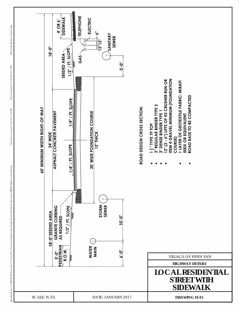
1/4"
/ F
T. SL
OPE
1/4"
/ F
T. SL
OPE
1/2"
/ F
T. SL
OPE
1/2"
/ F
T. SL
OPE
60' M
INIM
UM W
IDTH
RIG
HT-O
F-W
AY
18'-0
"SEED
ED A
REA
18'-0
"
WA
TER
MA
INST
ORM
SEW
ERSA
NIT
ARY
SEW
ER
SEED
ED A
REA
24' W
IDE
ASP
HALT
CO
NC
RETE
PA
VEM
ENT
5'-0
"
R.O
.W.
30' W
IDE
FOUN
DATIO
N C
OUR
SE12
" THI
CK
6'-0
"10
'-0"
5'-0
"
4' O
R 6'
SIDE
WA
LKG
RAN
ITE C
URBI
NG
AS
REQ
UIRE
D
ROA
D DE
SIG
N C
ROSS
SEC
TIO
N:
·1
1 2 " T
YPE
7F T
OP
·3"
REG
ULA
R BI
NDE
R TY
PE 3
·3"
DEN
SE B
INDE
R TY
PE 1
·12
" (2
- 6")
LIF
TS O
F #2
CRU
SHER
RUN
OR
ITEM
4 G
RAVE
L M
INIM
UM (F
OUN
DATI
ON
CO
URSE
)·
1 LA
YER
OF
GEO
TEXT
ILE
FABR
IC: M
IRA
FI50
0X O
R EQ
UIVA
LEN
T·
ROA
D BA
SE TO
BE
CO
MPA
CTE
D
12" 1
2"6"
GA
STE
LEPH
ON
E
ELEC
TRIC
PED
ESTR
IAN
DATE: JANUARY 2017
VILLAGE OF PENN YAN
Dra
win
g N
ame:
J:\
PRO
JEC
TS\P
enn
Yan_
V\C
omp
Plan
\F G
ener
al E
ngin
eerin
g\D
esig
n St
and
ard
s\M
aste
r Dra
win
gs\S
TREE
T\Hi
ghw
ay D
etai
ls.d
wg
Dat
e la
st a
cces
sed
: 2/2
0/20
17 1
:25
PMD
ate
last
plo
tted
: 2/2
0/20
17 2
:17
PMPl
otte
d B
y: M
aure
en N
alew
alsk
i
SCALE: N.T.S. DRAWING H-01
HIGHWAY DETAILS
LOCAL RESIDENTIALSTREET WITHSIDEWALK

20' W
IDE
ASP
HALT
CO
NC
RETE
PA
VEM
ENT
1/4"
/ F
T. SL
OPE
1/4"
/ F
T. SL
OPE
1/2"
/ F
T. SL
OPE
1/2"
/ F
T. SL
OPE
60' M
INIM
UM W
IDTH
RIG
HT-O
F-W
AY
5'-0
"PE
DES
TRIA
N
20'-0
"
GRA
NIT
E C
URBI
NG
AS
REQ
UIRE
D
SEED
ED A
REA
26' W
IDE
FOUN
DATIO
N C
OUR
SE12
" THI
CK
6' W
IDE
FOUN
DATI
ON
CO
URSE
12" T
HIC
K
8'-0
"A
SPHA
LTC
ON
CRE
TEPA
VEM
ENT
12'-0
"SE
EDED
ARE
A
R.O
.W.
5'-0
"PE
DEST
RIA
NR.
O.W
.
WA
TER
MA
INST
ORM
SEW
ERSA
NIT
ARY
SEW
ER6'
-0"
10'-0
"5'
-0"
ROA
D DE
SIG
N C
ROSS
SEC
TION
:
·1
1 2 " T
YPE
7F T
OP
·3"
REG
ULA
R BI
NDE
R TY
PE 3
·3"
DEN
SE B
INDE
R TY
PE 1
·12
" (2
- 6")
LIF
TS O
F #2
CRU
SHER
RUN
OR
ITEM
4 G
RAVE
L M
INIM
UM (F
OUN
DATI
ON
CO
URSE
)·
1 LA
YER
OF
GEO
TEXT
ILE
FABR
IC: M
IRA
FI50
0X O
R EQ
UIVA
LEN
T·
ROA
D BA
SE TO
BE
CO
MPA
CTE
D
12" 1
2"6"
GA
STE
LEPH
ON
EEL
ECTR
IC
DATE: JANUARY 2017
VILLAGE OF PENN YAN
Dra
win
g N
ame:
J:\
PRO
JEC
TS\P
enn
Yan_
V\C
omp
Plan
\F G
ener
al E
ngin
eerin
g\D
esig
n St
and
ard
s\M
aste
r Dra
win
gs\S
TREE
T\Hi
ghw
ay D
etai
ls.d
wg
Dat
e la
st a
cces
sed
: 2/2
0/20
17 1
:25
PMD
ate
last
plo
tted
: 2/2
0/20
17 2
:17
PMPl
otte
d B
y: M
aure
en N
alew
alsk
i
SCALE: N.T.S. DRAWING H-02
HIGHWAY DETAILS
LOCAL RESIDENTIALSTREET WITH PARKING
LANE

1/4"
/ F
T. SL
OPE
1/4"
/ F
T. SL
OPE
1/2"
/ F
T. SL
OPE
1/2"
/ F
T. SL
OPE
60' M
INIM
UM W
IDTH
RIG
HT-O
F-W
AY
18'-0
"SE
EDED
ARE
A18
'-0"
SEED
ED A
REA
24' W
IDE
ASP
HALT
CO
NC
RETE
PA
VEM
ENT
5'-0
"
30' W
IDE
FOUN
DATIO
N C
OUR
SE18
" THI
CK
6'-0
"SI
DEW
ALK
GRA
NIT
E C
URBI
NG
AS
REQ
UIRE
DPE
DES
TRIA
NR.
O.W
.
WA
TER
MA
INST
ORM
SEW
ERSA
NIT
ARY
SEW
ER6'
-0"
10'-0
"5'
-0"
ROA
D DE
SIG
N C
ROSS
SEC
TION
:
·1
1 2 " T
YPE
7F T
OP
·3"
REG
ULA
R BI
NDE
R TY
PE 3
·3"
DEN
SE B
INDE
R TY
PE 1
·18
" (3
- 6")
LIF
TS O
F #2
CRU
SHER
RUN
OR
ITEM
4 G
RAVE
L M
INIM
UM (F
OUN
DATI
ON
CO
URSE
)·
1 LA
YER
OF
GEO
TEXT
ILE
FABR
IC: M
IRA
FI50
0X O
R EQ
UIVA
LEN
T·
ROA
D BA
SE TO
BE
CO
MPA
CTE
D
12" 1
2"6"
GA
STE
LEPH
ON
E
ELEC
TRIC
DATE: JANUARY 2017
VILLAGE OF PENN YAN
Dra
win
g N
ame:
J:\
PRO
JEC
TS\P
enn
Yan_
V\C
omp
Plan
\F G
ener
al E
ngin
eerin
g\D
esig
n St
and
ard
s\M
aste
r Dra
win
gs\S
TREE
T\Hi
ghw
ay D
etai
ls.d
wg
Dat
e la
st a
cces
sed
: 2/2
0/20
17 1
:25
PMD
ate
last
plo
tted
: 2/2
0/20
17 2
:17
PMPl
otte
d B
y: M
aure
en N
alew
alsk
i
SCALE: N.T.S. DRAWING H-03
HIGHWAY DETAILS
PRIMARY OR MAJORTHOROUGHFAREWITH SIDEWALK

1/4"
/ F
T. SL
OPE
1/4"
/ F
T. SL
OPE
1"/F
T. M
IN. S
LOPE
80' M
INIM
UM W
IDTH
RIG
HT-O
F-W
AY
3'-0
"25
'-0"
SEED
ED A
REA
25'-0
"3'
-0"
24' W
IDE
ASP
HALT
CO
NC
RETE
PA
VEM
ENT
5'-0
"
30' W
IDE
FOUN
DATIO
N C
OUR
SE12
" THI
CK
SEED
ED A
REA
LOC
AL
RESI
DEN
TIAL
STRE
ET
BITU
MIN
OUS
SUR
FAC
E TR
EATM
ENT
1/4"
/ F
T. SL
OPE
1/4"
/ F
T. SL
OPE
1"/F
T. M
IN. S
LOPE
80' M
INIM
UM W
IDTH
RIG
HT-O
F-W
AY
3'-0
"23
'-0"
SEED
ED A
REA
23'-0
"3'
-0"
28' W
IDE
ASP
HALT
CO
NC
RETE
PA
VEM
ENT
5'-0
" PED
ESTR
AIN
R.O
.W.
34' W
IDE
FOUN
DATIO
N C
OUR
SE12
" THI
CK
SEED
ED A
REA
CO
LLEC
TOR
STRE
ET
BITU
MIN
OUS
SUR
FAC
E TR
EATM
ENT
1/4"
/ F
T. SL
OPE
1/4"
/ F
T. SL
OPE
1"/F
T. M
IN. S
LOPE
80' M
INIM
UM W
IDTH
RIG
HT-O
F-W
AY
3'-0
"23
'-0"
SEED
ED A
REA
23'-0
"3'
-0"
28' W
IDE
ASP
HALT
CO
NC
RETE
PA
VEM
ENT
5'-0
" PED
ESTR
IAN
R.O
.W.
34' W
IDE
FOUN
DATIO
N C
OUR
SE18
" THI
CK
SEED
ED A
REA
PRIM
ARY
OR
MA
JOR
THO
ROUG
HFA
RE
BITU
MIN
OUS
SUR
FAC
E TR
EATM
ENT
(INC
LUDI
NG
ALL
STR
EETS
SER
VIN
G C
OM
MER
CIA
L A
ND
IND
USTR
IAL
SUBD
IVIS
ION
S)
PEDE
STRI
ANR.
O.W
.
DRA
INA
GE
SWA
LE
1"/F
T. M
IN.
SLO
PE
5'-0
"PE
DES
TRIA
NR.
O.W
.
1"/F
T. M
IN.
SLO
PE
DRA
INA
GE
SWA
LE5'
-0"
PED
ESTR
IAN
R.O
.W.
NO
TES:
1.RO
ADS
IDE
SWA
LES
REQ
UIRE
PLA
NN
ING
BO
ARD
APP
ROVA
L
1"/F
T. M
IN.
SLO
PE
DRA
INA
GE
SWA
LE
5'-0
"PE
DES
TRIA
NR.
O.W
.
DATE: JANUARY 2017
VILLAGE OF PENN YAN
Dra
win
g N
ame:
J:\
PRO
JEC
TS\P
enn
Yan_
V\C
omp
Plan
\F G
ener
al E
ngin
eerin
g\D
esig
n St
and
ard
s\M
aste
r Dra
win
gs\S
TREE
T\Hi
ghw
ay D
etai
ls.d
wg
Dat
e la
st a
cces
sed
: 2/2
0/20
17 1
:25
PMD
ate
last
plo
tted
: 2/2
0/20
17 2
:17
PMPl
otte
d B
y: M
aure
en N
alew
alsk
i
SCALE: N.T.S. DRAWING H-04
HIGHWAY DETAILS
TYPICAL ROADSECTIONS
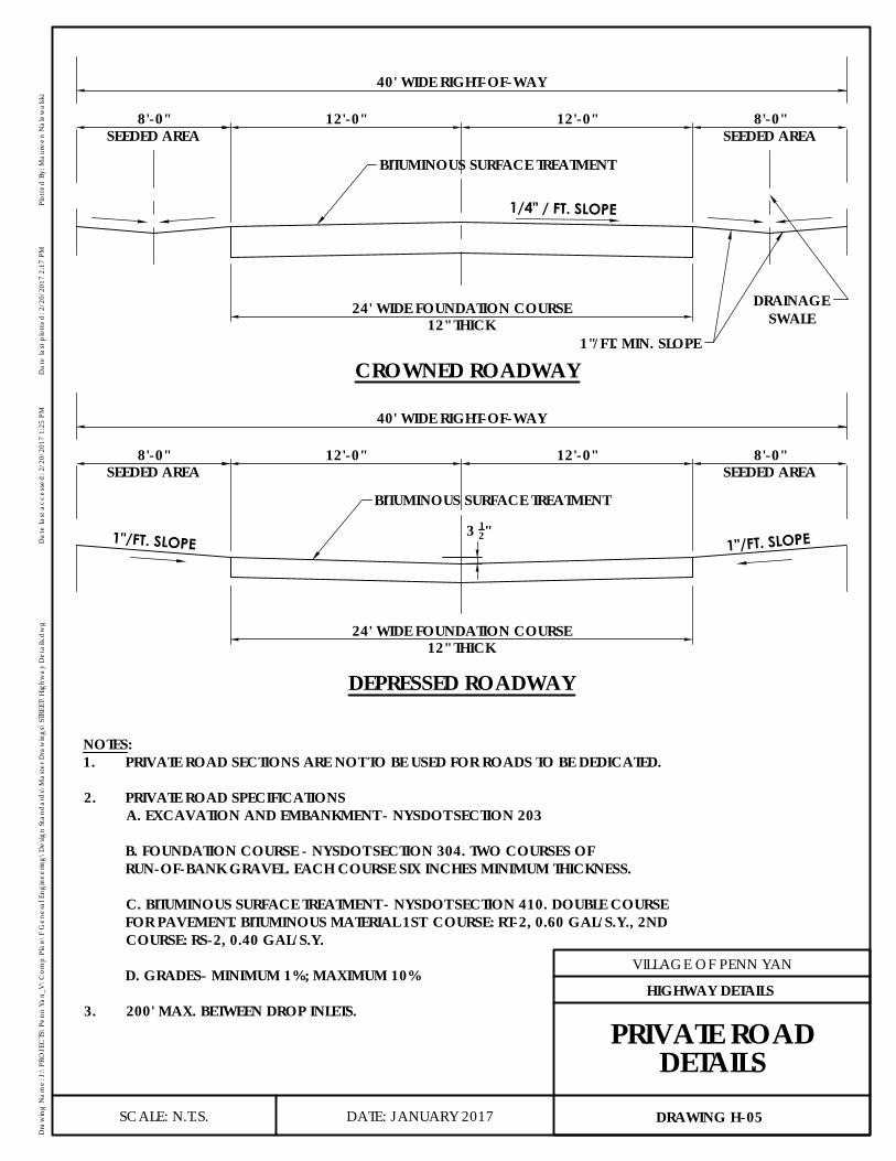
1/4" / FT. SLOPE
40' WIDE RIGHT-OF-WAY
8'-0"
24' WIDE FOUNDATION COURSE12" THICK
SEEDED AREA
CROWNED ROADWAY
BITUMINOUS SURFACE TREATMENT
12'-0" 12'-0"
DRAINAGESWALE
8'-0"SEEDED AREA
1"/FT. MIN. SLOPE
40' WIDE RIGHT-OF-WAY
8'-0"
24' WIDE FOUNDATION COURSE12" THICK
SEEDED AREA
DEPRESSED ROADWAY
BITUMINOUS SURFACE TREATMENT
12'-0" 12'-0"8'-0"SEEDED AREA
3 12" 1"/FT. SLOPE1"/FT. SLOPE
NOTES:1. PRIVATE ROAD SECTIONS ARE NOT TO BE USED FOR ROADS TO BE DEDICATED.
2. PRIVATE ROAD SPECIFICATIONSA. EXCAVATION AND EMBANKMENT - NYSDOT SECTION 203
B. FOUNDATION COURSE - NYSDOT SECTION 304. TWO COURSES OF RUN-OF-BANK GRAVEL. EACH COURSE SIX INCHES MINIMUM THICKNESS.
C. BITUMINOUS SURFACE TREATMENT - NYSDOT SECTION 410. DOUBLE COURSE FOR PAVEMENT. BITUMINOUS MATERIAL 1ST COURSE: RT-2, 0.60 GAL/S.Y., 2NDCOURSE: RS-2, 0.40 GAL/S.Y.
D. GRADES- MINIMUM 1%; MAXIMUM 10%
3. 200' MAX. BETWEEN DROP INLETS.
DATE: JANUARY 2017
VILLAGE OF PENN YAN
Dra
win
g N
ame:
J:\
PRO
JEC
TS\P
enn
Yan_
V\C
omp
Plan
\F G
ener
al E
ngin
eerin
g\D
esig
n St
and
ard
s\M
aste
r Dra
win
gs\S
TREE
T\Hi
ghw
ay D
etai
ls.d
wg
Dat
e la
st a
cces
sed
: 2/2
0/20
17 1
:25
PMD
ate
last
plo
tted
: 2/2
0/20
17 2
:17
PMPl
otte
d B
y: M
aure
en N
alew
alsk
i
SCALE: N.T.S. DRAWING H-05
HIGHWAY DETAILS
PRIVATE ROADDETAILS

SECTION
W
6"
PROPOSED CONCRETE SIDEWALK3/4" SLOPE TOWARD STREET
NOTES:1. SIDEWALK IN LAWN SHALL BE 4" THICK. SIDEWALK IN DRIVEWAY SHALL BE 6"
THICK. CONCRETE SHALL BE 4000 PSI CONCRETE WITH FIBER, AT 28 DAY CURETIME.
2. PROVIDE TRANSVERSE CONSTRUCTION JOINTS FOR ALL SLABS OVER WATERSERVICES AND BUILDING SEWERS.
3. ALL SCORED JOINTS WILL BE 14 INCH MINIMUM IN WIDTH AND 14 OF THETHICKNESS OF THE CONCRETE.
4. MAXIMUM UNSCORED AREA ALLOWED IS 36 SQUARE FEET OR 6 X 6 FOOTFLAGS.
5. MINIMUM WIDTH SHALL BE 4 - FEET, WITH 6 - FEET WIDTH WHERE DEEMED NECESSARY BY THE VILLAGE
6" RUN OF BANKGRAVEL BASE
4'-0" 4'-0" 4'-0" 4'-0"
1 EXPANSION JOINT WITH PREMOLDED BITUMINOUS JOINT FILLER
2 DUMMY JOINT
1 12 2 2
16'-0"
PLAN
SLOPE TOWARDSSTREET
W
W + 1'
MINIMUMCONCRETETHICKNESSSEE NOTE 1.
COMPACTED SUBGRADE
DATE: JANUARY 2017
VILLAGE OF PENN YAN
Dra
win
g N
ame:
J:\
PRO
JEC
TS\P
enn
Yan_
V\C
omp
Plan
\F G
ener
al E
ngin
eerin
g\D
esig
n St
and
ard
s\M
aste
r Dra
win
gs\S
TREE
T\Hi
ghw
ay D
etai
ls.d
wg
Dat
e la
st a
cces
sed
: 2/2
0/20
17 1
:25
PMD
ate
last
plo
tted
: 2/2
0/20
17 2
:17
PMPl
otte
d B
y: M
aure
en N
alew
alsk
i
SCALE: N.T.S. DRAWING H-06
HIGHWAY DETAILS
CONCRETESIDEWALK
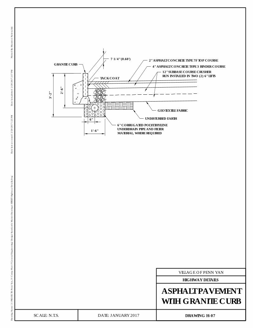
1'-6"
6"
2'-6
"
3'-2
"
7 1/4" (0.60')
6" CORRUGATED POLYETHYLENEUNDERDRAIN PIPE AND FILTERMATERIAL, WHERE REQUIRED
UNDISTURBED EARTH
GEOTEXTILE FABRIC
TACK COAT
GRANITE CURB2" ASPHALT CONCRETE TYPE 7F TOP COURSE
4" ASPHALT CONCRETE TYPE 3 BINDER COURSE12" SUBBASE COURSE CRUSHERRUN INSTALLED IN TWO (2) 6" LIFTS
DATE: JANUARY 2017
VILLAGE OF PENN YAN
Dra
win
g N
ame:
J:\
PRO
JEC
TS\P
enn
Yan_
V\C
omp
Plan
\F G
ener
al E
ngin
eerin
g\D
esig
n St
and
ard
s\M
aste
r Dra
win
gs\S
TREE
T\Hi
ghw
ay D
etai
ls.d
wg
Dat
e la
st a
cces
sed
: 2/2
0/20
17 1
:25
PMD
ate
last
plo
tted
: 2/2
0/20
17 2
:17
PMPl
otte
d B
y: M
aure
en N
alew
alsk
i
SCALE: N.T.S. DRAWING H-07
HIGHWAY DETAILS
ASPHALT PAVEMENTWITH GRANITE CURB

COLLECTOR ROAD
1-1/2" TYPE 7F TOP (NYSDOT ITEM NO 403.1901)3" TYPE 3 BINDER (NYSDOT ITEM NO 403.13)(1) 3" LIFT CRUSHER RUN STONE(NYSDOT SPEC 304-2.02 TYPE 2)
(2) 6" LIFTS NO 2 & NO 3 CRUSHED STONE EQUALLYMIXED (NYSDOT GRADATION TABLE 703-4)
GEOTEXTILE FABRIC AS REQUIREDCOMPACED SUBSOIL
LOCAL ROAD
1-1/2" TYPE 7F TOP (NYSDOT ITEM NO 403.1901)3" TYPE 3 BINDER (NYSDOT ITEM NO 403.13)
(1) 3" LIFT CRUSHER RUN STONE(NYSDOT SPEC 304-2.02 TYPE 2)
(2) 6" LIFTS NO 2 & NO 3 CRUSHED STONE EQUALLYMIXED (NYSDOT GRADATION TABLE 703-4)
GEOTEXTILE FABRIC AS REQUIREDCOMPACED SUBSOIL
INDUSTRIAL ROAD
1-1/2" TYPE 7F TOP (NYSDOT ITEM NO 403.1901)3" TYPE 3 BINDER (NYSDOT ITEM NO 403.13)3" TYPE 1 BASE (NYSDOT ITEM NO 403.11)(1) 3" LIFT CRUSHER RUN STONE(NYSDOT SPEC 304-2.02 TYPE 2)
(2) 6" LIFTS NO 2 & NO 3 CRUSHED STONE EQUALLYMIXED (NYSDOT GRADATION TABLE 703-4)GEOTEXTILE FABRIC AS REQUIRED
COMPACED SUBSOIL
(1) 3" LIFT CRUSHER RUN STONE(NYSDOT SPEC 304-2.02 TYPE 2)
(1) 6" LIFT NO 2 & NO 3 CRUSHED STONE EQUALLYMIXED (NYSDOT GRADATION TABLE 703-4)
GEOTEXTILE FABRIC AS REQUIREDCOMPACED SUBSOIL PRIVATE DRIVE
DATE: JANUARY 2017
VILLAGE OF PENN YAN
Dra
win
g N
ame:
J:\
PRO
JEC
TS\P
enn
Yan_
V\C
omp
Plan
\F G
ener
al E
ngin
eerin
g\D
esig
n St
and
ard
s\M
aste
r Dra
win
gs\S
TREE
T\Hi
ghw
ay D
etai
ls.d
wg
Dat
e la
st a
cces
sed
: 2/2
0/20
17 1
:25
PMD
ate
last
plo
tted
: 2/2
0/20
17 2
:17
PMPl
otte
d B
y: M
aure
en N
alew
alsk
i
SCALE: N.T.S. DRAWING H-08
HIGHWAY DETAILS
TYPICAL ROADPAVEMENT SECTIONS
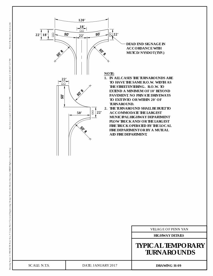
22'50' 50'
120'
22'18'22'
22'
22'
50'
50'
50' R
50' R
50' R
50' R
18'
DEAD END SIGNAGE INACCORDANCE WITHMUTCD/NYSDOT (TYP.)
1. IN ALL CASES THE TURNAROUNDS ARETO HAVE THE SAME R.O.W. WIDTH ASTHE STREET ENTERING. R.O.W. TOEXTEND A MINIMUM OF 10' BEYONDPAVEMENT. NO PRIVATE DRIVEWAYSTO EXIT INTO OR WITHIN 20' OFTURNAROUND.
2. THE TURNAROUND SHALL BE BUILT TOACCOMMODATE THE LARGESTMUNICIPAL HIGHWAY DEPARTMENTPLOW TRUCK AND/OR THE LARGESTFIRE TRUCK OPERATED BY THE LOCALFIRE DEPARTMENT OR BY A MUTUALAID FIRE DEPARTMENT.
NOTE:
DATE: JANUARY 2017
VILLAGE OF PENN YAN
Dra
win
g N
ame:
J:\
PRO
JEC
TS\P
enn
Yan_
V\C
omp
Plan
\F G
ener
al E
ngin
eerin
g\D
esig
n St
and
ard
s\M
aste
r Dra
win
gs\S
TREE
T\Hi
ghw
ay D
etai
ls.d
wg
Dat
e la
st a
cces
sed
: 2/2
0/20
17 1
:25
PMD
ate
last
plo
tted
: 2/2
0/20
17 2
:17
PMPl
otte
d B
y: M
aure
en N
alew
alsk
i
SCALE: N.T.S. DRAWING H-09
HIGHWAY DETAILS
TYPICAL TEMPORARYTURNAROUNDS
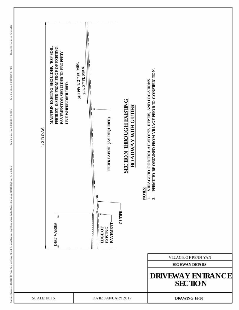
DIST
. VA
RIES
1/2
R.O
.W.
MA
INTA
IN E
XIST
ING
SHO
ULDE
R. T
OP
SOIL
,FE
RTIL
IZE,
& S
EED
FRO
M E
DGE
OF
EXIS
TING
PAVE
MEN
T OR
SHO
ULDE
R TO
PRO
PERT
YLI
NE
WHE
RE D
ISTU
RBED
.
SLO
PE: 1
/2"/
FT. M
IN.
1
-1/2
"/FT
. MA
X.
GUT
TER
EDG
E O
FEX
ISTIN
GPA
VEM
ENT
SEC
TION
THRO
UGH
EXIS
TING
ROA
DWA
Y W
ITH G
UTTE
R
NO
TES:
1.VI
LLA
GE
TO C
ON
TRO
L A
LL S
LOPE
S, D
EPTH
S, A
ND
LOC
ATIO
NS.
2.PE
RMIT
TO B
E O
BTA
INED
FRO
M V
ILLA
GE
PRIO
R TO
CO
NST
RUC
TION
.
FILT
ER F
ABR
IC (A
S RE
QUI
RED)
DATE: JANUARY 2017
VILLAGE OF PENN YAN
Dra
win
g N
ame:
J:\
PRO
JEC
TS\P
enn
Yan_
V\C
omp
Plan
\F G
ener
al E
ngin
eerin
g\D
esig
n St
and
ard
s\M
aste
r Dra
win
gs\S
TREE
T\Hi
ghw
ay D
etai
ls.d
wg
Dat
e la
st a
cces
sed
: 2/2
0/20
17 1
:25
PMD
ate
last
plo
tted
: 2/2
0/20
17 2
:17
PMPl
otte
d B
y: M
aure
en N
alew
alsk
i
SCALE: N.T.S. DRAWING H-10
HIGHWAY DETAILS
DRIVEWAY ENTRANCESECTION
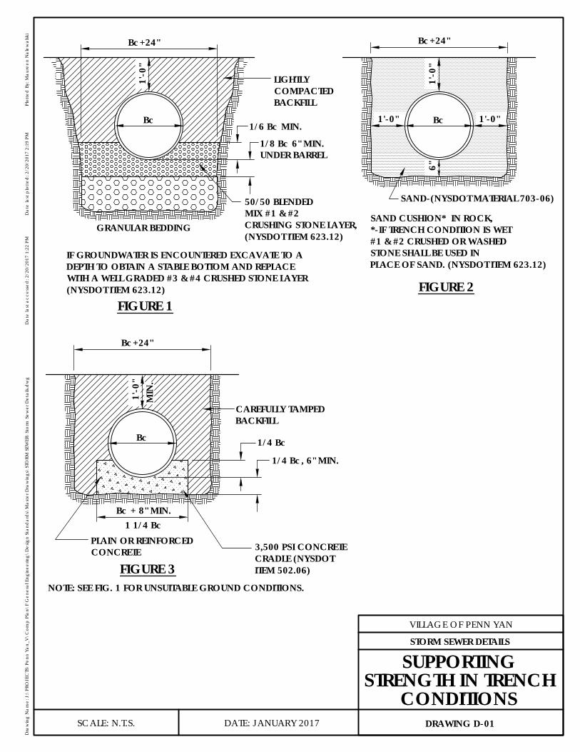
Bc 1'-0"1'-0"
6"1'
-0"
Bc+24"Bc+24"
1'-0
"
Bc
Bc+24"
1'-0
"
Bc
MIN
.
Bc + 8" MIN.1 1/4 Bc
1/4 Bc
1/4 Bc, 6" MIN.
NOTE: SEE FIG. 1 FOR UNSUITABLE GROUND CONDITIONS.
FIGURE 3
SAND-(NYSDOT MATERIAL 703-06)
FIGURE 2FIGURE 1
1/6 Bc MIN.
GRANULAR BEDDING
LIGHTLYCOMPACTEDBACKFILL
1/8 Bc 6" MIN.UNDER BARREL
50/50 BLENDEDMIX #1 & #2CRUSHING STONE LAYER,(NYSDOT ITEM 623.12)
IF GROUNDWATER IS ENCOUNTERED EXCAVATE TO ADEPTH TO OBTAIN A STABLE BOTTOM AND REPLACEWITH A WELL GRADED #3 & #4 CRUSHED STONE LAYER(NYSDOT ITEM 623.12)
SAND CUSHION* IN ROCK,*-IF TRENCH CONDITION IS WET#1 & #2 CRUSHED OR WASHEDSTONE SHALL BE USED INPLACE OF SAND. (NYSDOT ITEM 623.12)
CAREFULLY TAMPEDBACKFILL
PLAIN OR REINFORCEDCONCRETE 3,500 PSI CONCRETE
CRADLE (NYSDOTITEM 502.06)
DATE: JANUARY 2017
VILLAGE OF PENN YAN
Dra
win
g N
ame:
J:\
PRO
JEC
TS\P
enn
Yan_
V\C
omp
Plan
\F G
ener
al E
ngin
eerin
g\D
esig
n St
and
ard
s\M
aste
r Dra
win
gs\S
TORM
SEW
ER\S
torm
Sew
er D
etai
ls.d
wg
Dat
e la
st a
cces
sed
: 2/2
0/20
17 1
:22
PMD
ate
last
plo
tted
: 2/2
0/20
17 2
:19
PMPl
otte
d B
y: M
aure
en N
alew
alsk
i
SCALE: N.T.S. DRAWING D-01
STORM SEWER DETAILS
SUPPORTINGSTRENGTH IN TRENCH
CONDITIONS

R=B/2
B*
R=B/
2
R=B/
2
SLOPE HSLOPE H
R=B/
2
B
R=B/2
SLOPE H
B
SLOPE H
SLOPE GSLOPE H
AR=
A/2+C
MH CL C
MAX. PIPEDIA.
DIM
ENSI
ON
ABCGH
8"
.10'
.05'4"4'-0"4'-0"
15"
5'-0"4'-0"
8".02'.05'
18"4'-0"
9"
21"
5'-0"5'-0"
10"
24"
*5'-0"
12"
27"
*5'-0"
13.5"
30"
*6'-0"
15" 18"
**
36"
.10'
.05'6"
4'-0"5'-0"
12"
5'-0"
.02'
.05'.02'.05'
.02'
.05'.02'.05'
.02'
.05'.02'.05'
CL
CL
WHEN A SMALLER SEWER JOINS A LARGERONE, THE TOP OF PIPE SHALL BE MATCHED ATTHE SAME ELEVATION.
NOTES:1. WHEN A SMALLER SEWER JOINS A LARGER ONE,
THE TOP OF PIPE SHALL BE MATCHED AT THESAME ELEVATION
* FOR PIPE DIAMETERS GREATER THAN 24" DIA. DESIGN ENGINEER SHALLPROVIDE SPECIAL DESIGN DETAILS SHOWING MANHOLE SIZE, MATERIAL,INVERT, BENCH WALLS, & ANY OTHER PERTINENT FEATURES FOR VILLAGEENGINEER APPROVAL.
CENTERLINE OF SEWER &MANHOLE
CL SEWER
DATE: JANUARY 2017
VILLAGE OF PENN YAN
Dra
win
g N
ame:
J:\
PRO
JEC
TS\P
enn
Yan_
V\C
omp
Plan
\F G
ener
al E
ngin
eerin
g\D
esig
n St
and
ard
s\M
aste
r Dra
win
gs\S
TORM
SEW
ER\S
torm
Sew
er D
etai
ls.d
wg
Dat
e la
st a
cces
sed
: 2/2
0/20
17 1
:22
PMD
ate
last
plo
tted
: 2/2
0/20
17 2
:19
PMPl
otte
d B
y: M
aure
en N
alew
alsk
i
SCALE: N.T.S. DRAWING D-02
STORM SEWER DETAILS
STORM SEWERSTANDARD MANHOLE
DIMENSIONS
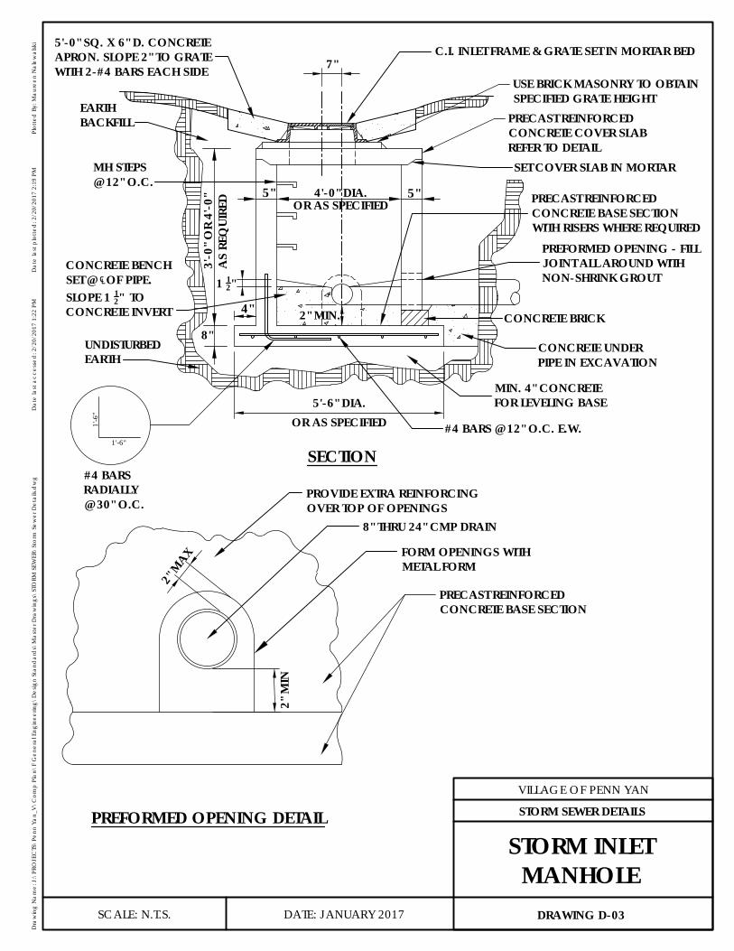
SECTION
4'-0" DIA.3'
-0" O
R 4'
-0"
8"
OR AS SPECIFIEDA
S RE
QUI
RED
5'-6" DIA.
PRECAST REINFORCEDCONCRETE COVER SLABREFER TO DETAIL
OR AS SPECIFIED
5" 5"
PREFORMED OPENING DETAIL
1 12"
2" MIN.4"
1'-6"
1'-6
"USE BRICK MASONRY TO OBTAINSPECIFIED GRATE HEIGHT
EARTHBACKFILL
MH STEPS@ 12" O.C.
UNDISTURBEDEARTH
C.I. INLET FRAME & GRATE SET IN MORTAR BED5'-0" SQ. X 6" D. CONCRETEAPRON. SLOPE 2" TO GRATEWITH 2-#4 BARS EACH SIDE
#4 BARSRADIALLY@ 30" O.C.
#4 BARS @ 12" O.C. E.W.
CONCRETE BRICK
CONCRETE UNDERPIPE IN EXCAVATION
MIN. 4" CONCRETEFOR LEVELING BASE
SET COVER SLAB IN MORTAR
CONCRETE BENCHSET @ ℄OF PIPE.SLOPE 1 12" TOCONCRETE INVERT
PRECAST REINFORCEDCONCRETE BASE SECTIONWITH RISERS WHERE REQUIRED
PREFORMED OPENING - FILLJOINT ALL AROUND WITHNON-SHRINK GROUT
PRECAST REINFORCEDCONCRETE BASE SECTION
PROVIDE EXTRA REINFORCINGOVER TOP OF OPENINGS
8" THRU 24" CMP DRAIN
FORM OPENINGS WITHMETAL FORM
2" M
AX
2" M
IN
7"
DATE: JANUARY 2017
VILLAGE OF PENN YAN
Dra
win
g N
ame:
J:\
PRO
JEC
TS\P
enn
Yan_
V\C
omp
Plan
\F G
ener
al E
ngin
eerin
g\D
esig
n St
and
ard
s\M
aste
r Dra
win
gs\S
TORM
SEW
ER\S
torm
Sew
er D
etai
ls.d
wg
Dat
e la
st a
cces
sed
: 2/2
0/20
17 1
:22
PMD
ate
last
plo
tted
: 2/2
0/20
17 2
:19
PMPl
otte
d B
y: M
aure
en N
alew
alsk
i
SCALE: N.T.S. DRAWING D-03
STORM SEWER DETAILS
STORM INLETMANHOLE
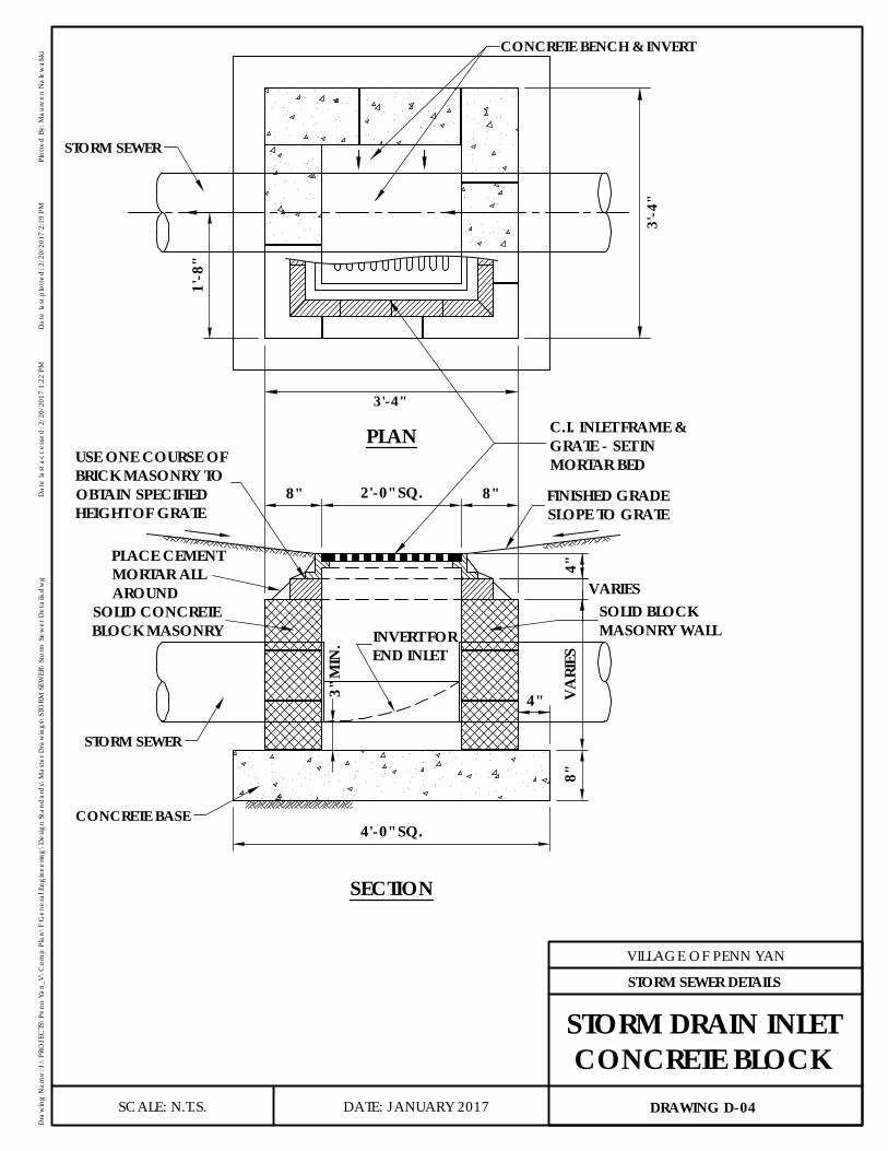
3'-4"
3'-4
"
STORM SEWER
CONCRETE BENCH & INVERT
1'-8
"
PLAN
4"
8"
8" 8"2'-0" SQ.
VARI
ES4"
3" M
IN.
4'-0" SQ.
STORM SEWER
SECTION
VARIES
FINISHED GRADESLOPE TO GRATE
C.I. INLET FRAME &GRATE - SET INMORTAR BED
CONCRETE BASE
INVERT FOREND INLET
SOLID BLOCKMASONRY WALL
USE ONE COURSE OFBRICK MASONRY TOOBTAIN SPECIFIEDHEIGHT OF GRATE
SOLID CONCRETEBLOCK MASONRY
PLACE CEMENTMORTAR ALLAROUND
DATE: JANUARY 2017
VILLAGE OF PENN YAN
Dra
win
g N
ame:
J:\
PRO
JEC
TS\P
enn
Yan_
V\C
omp
Plan
\F G
ener
al E
ngin
eerin
g\D
esig
n St
and
ard
s\M
aste
r Dra
win
gs\S
TORM
SEW
ER\S
torm
Sew
er D
etai
ls.d
wg
Dat
e la
st a
cces
sed
: 2/2
0/20
17 1
:22
PMD
ate
last
plo
tted
: 2/2
0/20
17 2
:19
PMPl
otte
d B
y: M
aure
en N
alew
alsk
i
SCALE: N.T.S. DRAWING D-04
STORM SEWER DETAILS
STORM DRAIN INLETCONCRETE BLOCK
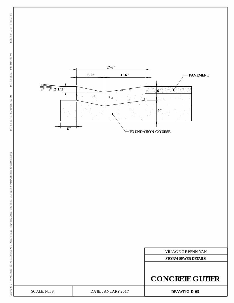
1'-0" 1'-6"
2'-6"
FOUNDATION COURSE
PAVEMENT
2 1/2" 6"
9"
6"
DATE: JANUARY 2017
VILLAGE OF PENN YAN
Dra
win
g N
ame:
J:\
PRO
JEC
TS\P
enn
Yan_
V\C
omp
Plan
\F G
ener
al E
ngin
eerin
g\D
esig
n St
and
ard
s\M
aste
r Dra
win
gs\S
TORM
SEW
ER\S
torm
Sew
er D
etai
ls.d
wg
Dat
e la
st a
cces
sed
: 2/2
0/20
17 1
:22
PMD
ate
last
plo
tted
: 2/2
0/20
17 2
:19
PMPl
otte
d B
y: M
aure
en N
alew
alsk
i
SCALE: N.T.S. DRAWING D-05
STORM SEWER DETAILS
CONCRETE GUTTER

2'-6" 2'-6"5'-0"
CL1'-0"
1'-6"
2'-6"
NOTE: CONCRETE APRONS SHALL BE 6" THICK.
EDGE PAVEMENT
REINFORCED CONCRETE APRON2-#4 BARS, 4'-8" LONG ON ALL 4 SIDES
CONCRETEGUTTER
ALTERNATE EDGEAT END OF GUTTER
DATE: JANUARY 2017
VILLAGE OF PENN YAN
Dra
win
g N
ame:
J:\
PRO
JEC
TS\P
enn
Yan_
V\C
omp
Plan
\F G
ener
al E
ngin
eerin
g\D
esig
n St
and
ard
s\M
aste
r Dra
win
gs\S
TORM
SEW
ER\S
torm
Sew
er D
etai
ls.d
wg
Dat
e la
st a
cces
sed
: 2/2
0/20
17 1
:22
PMD
ate
last
plo
tted
: 2/2
0/20
17 2
:19
PMPl
otte
d B
y: M
aure
en N
alew
alsk
i
SCALE: N.T.S. DRAWING D-06
STORM SEWER DETAILS
GUTTER INLET
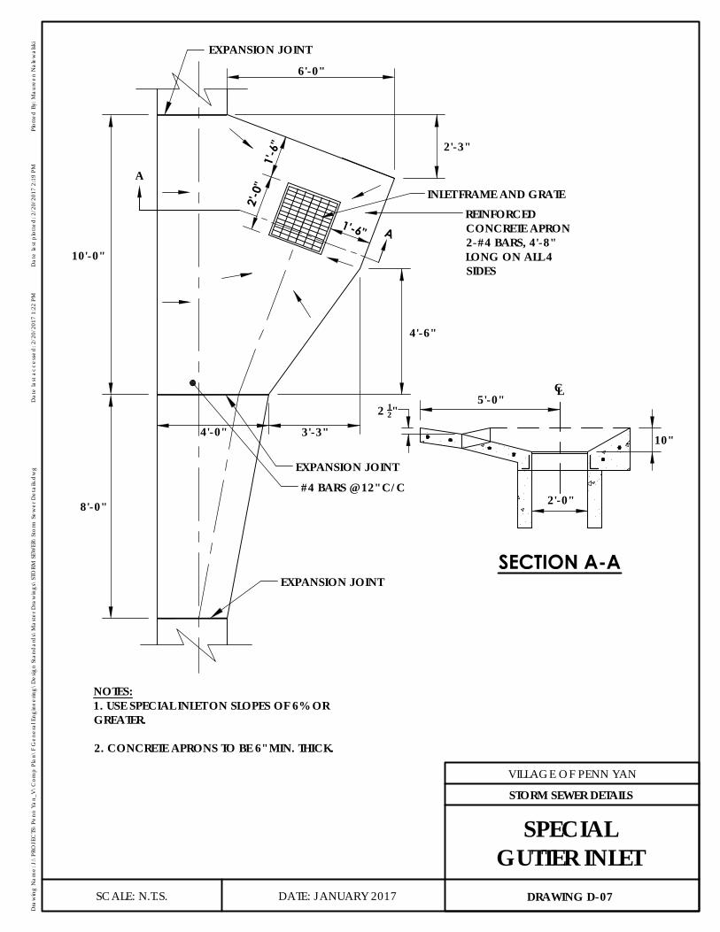
10'-0"
8'-0"
INLET FRAME AND GRATE
EXPANSION JOINT
2'-3"
1'-6"
6'-0"
3'-3"
4'-6"
1'-6
"
2'-0
"
EXPANSION JOINT
EXPANSION JOINT
4'-0"
A
A
#4 BARS @ 12" C/C
NOTES:1. USE SPECIAL INLET ON SLOPES OF 6% ORGREATER.
2. CONCRETE APRONS TO BE 6" MIN. THICK.
REINFORCEDCONCRETE APRON2-#4 BARS, 4'-8"LONG ON ALL 4SIDES
2'-0"
10"
5'-0"2 12"
CL
SECTION A-A
DATE: JANUARY 2017
VILLAGE OF PENN YAN
Dra
win
g N
ame:
J:\
PRO
JEC
TS\P
enn
Yan_
V\C
omp
Plan
\F G
ener
al E
ngin
eerin
g\D
esig
n St
and
ard
s\M
aste
r Dra
win
gs\S
TORM
SEW
ER\S
torm
Sew
er D
etai
ls.d
wg
Dat
e la
st a
cces
sed
: 2/2
0/20
17 1
:22
PMD
ate
last
plo
tted
: 2/2
0/20
17 2
:19
PMPl
otte
d B
y: M
aure
en N
alew
alsk
i
SCALE: N.T.S. DRAWING D-07
STORM SEWER DETAILS
SPECIALGUTTER INLET
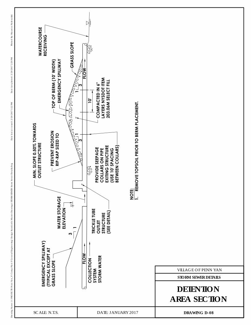
GRA
SS S
LOPE
EMER
GEN
CY
SPIL
LWA
YTO
P O
F BE
RM (1
0' W
IDTH
)
31
31
31
FLO
W
FLO
W10
'PR
OVI
DE S
EEPA
GE
CO
LLA
RS O
N P
IPE
EXITI
NG
STR
UCTU
RE(U
SE 1
0' S
PAC
ING
BETW
EEN
CO
LLA
RS)
CO
LLEC
TION
SYST
EMST
ORM
WA
TER
EMER
GEN
CY
SPIL
LWA
Y)(T
YPIC
AL
EXC
EPT
AT
GRA
SS S
LOPE
WA
TER
STO
RAG
EEL
EVA
TION
TRIC
KLE
TUBE
OUT
LET
STRU
CTU
RE(S
EE D
ETA
IL)
MIN
. SLO
PE 0
.50%
TOW
ARD
SO
UTLE
T STR
UCTU
RE
PREV
ENT E
ROSI
ON
RIP-
RAP
SIZE
D TO
NO
TE:
1.RE
MO
VE TO
PSO
IL P
RIO
R TO
BER
M P
LAC
EMEN
T.
CO
MPA
CTE
D IN
6"
LAYE
RS N
YSDO
T IT
EM20
3.06
M S
ELEC
T FIL
L
WA
TERC
OUR
SERE
CEI
VIN
G
DATE: JANUARY 2017
VILLAGE OF PENN YAN
Dra
win
g N
ame:
J:\
PRO
JEC
TS\P
enn
Yan_
V\C
omp
Plan
\F G
ener
al E
ngin
eerin
g\D
esig
n St
and
ard
s\M
aste
r Dra
win
gs\S
TORM
SEW
ER\S
torm
Sew
er D
etai
ls.d
wg
Dat
e la
st a
cces
sed
: 2/2
0/20
17 1
:22
PMD
ate
last
plo
tted
: 2/2
0/20
17 2
:20
PMPl
otte
d B
y: M
aure
en N
alew
alsk
i
SCALE: N.T.S. DRAWING D-08
STORM SEWER DETAILS
DETENTIONAREA SECTION

6" MIN.
SLOPE 0.50% MIN.
6' M
AX.
MIN. 36"DIA. RISER
FLOW
TRASH RACK (WELDED REBAR)
1' MIN.
1' MIN. HWL 10
0.5' MAX. STORMWATER FLOW DEPTH OVER EMERGENCY SPILLWAY, 100 YR. STORM
EL. TOP OF BERM
HWL 100 EL.EMERG.SPILLWAY
OUTFLOW PIPE,CAPABLE OF PASSING10 YEAR STORM
SLOPE BOTTOM OFPOND TOWARDSOUTLET
NOTES:1. REMOVE TOPSOIL PRIOR TO
BERM PLACEMENT.
8" MIN. DIA. INFLOW PIPE,THROTTLES 2 AND 5 YEAR STORMS
DATE: JANUARY 2017
VILLAGE OF PENN YAN
Dra
win
g N
ame:
J:\
PRO
JEC
TS\P
enn
Yan_
V\C
omp
Plan
\F G
ener
al E
ngin
eerin
g\D
esig
n St
and
ard
s\M
aste
r Dra
win
gs\S
TORM
SEW
ER\S
torm
Sew
er D
etai
ls.d
wg
Dat
e la
st a
cces
sed
: 2/2
0/20
17 1
:22
PMD
ate
last
plo
tted
: 2/2
0/20
17 2
:20
PMPl
otte
d B
y: M
aure
en N
alew
alsk
i
SCALE: N.T.S. DRAWING D-09
STORM SEWER DETAILS
TRICKLE TUBEOUTLET STRUCTURE
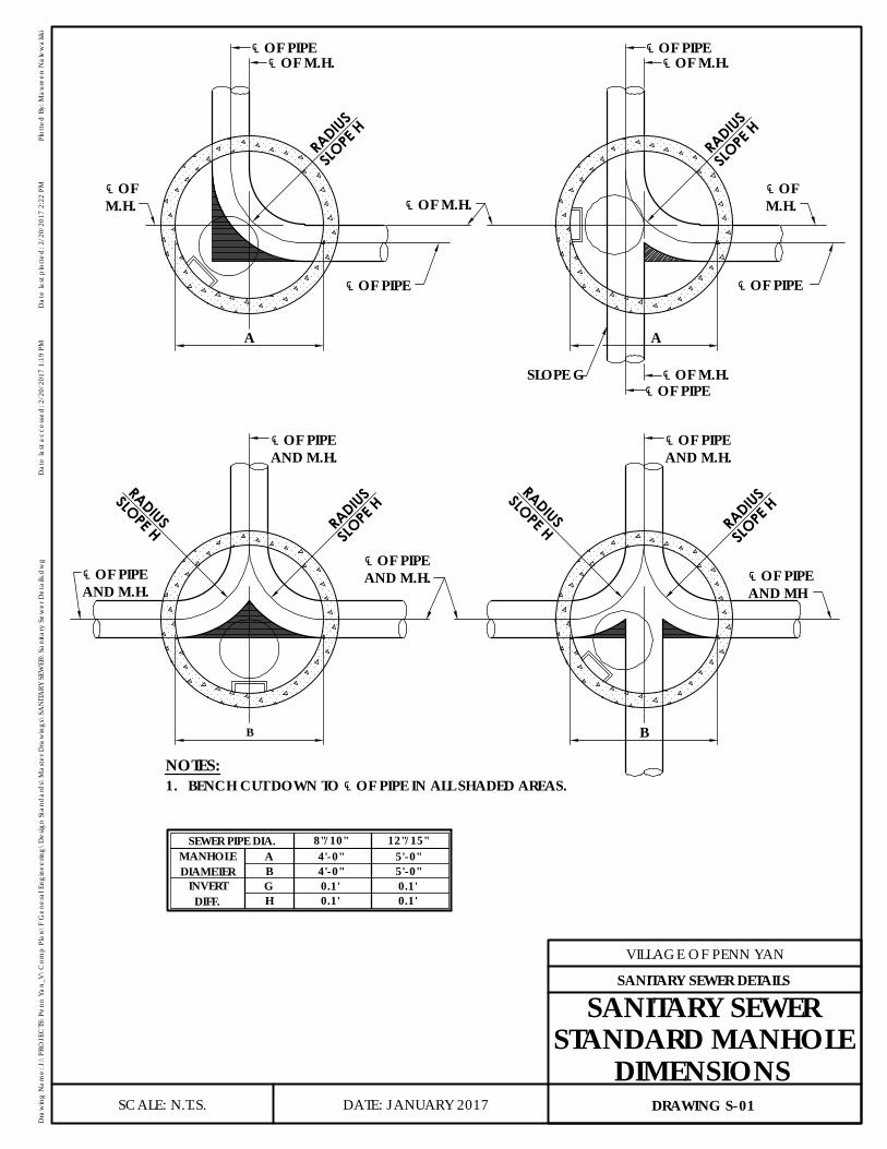
5'-0"5'-0"
0.1'0.1'
12"/15"
1.NOTES:
8"/10"SEWER PIPE DIA.
DIFF.INVERT
DIAMETERMANHOLE
BA
GH 0.1'
0.1'
4'-0"4'-0"
SLOPE
H
RADIUSB
RADIUS
SLOPE H
SLOPE H
RADIUS
B
RADIUS
SLOPE
HSLOPE G
A
RADIUS
SLOPE
H
SLOPE
HRA
DIUS
A
℄ OF PIPEAND M.H.
℄ OF PIPEAND M.H.
℄ OF PIPEAND M.H.
℄ OF PIPEAND M.H.
℄ OF PIPEAND MH
℄ OFM.H.
℄ OFM.H.
℄ OF PIPE℄ OF M.H.
℄ OF PIPE
℄ OF M.H.℄ OF PIPE
℄ OF M.H.
℄ OF PIPE
℄ OF M.H.℄ OF PIPE
BENCH CUT DOWN TO ℄ OF PIPE IN ALL SHADED AREAS.
DATE: JANUARY 2017
VILLAGE OF PENN YAN
Dra
win
g N
ame:
J:\
PRO
JEC
TS\P
enn
Yan_
V\C
omp
Plan
\F G
ener
al E
ngin
eerin
g\D
esig
n St
and
ard
s\M
aste
r Dra
win
gs\S
AN
ITARY
SEW
ER\S
anita
ry S
ewer
Det
ails.
dw
gD
ate
last
acc
esse
d: 2
/20/
2017
1:1
9 PM
Dat
e la
st p
lotte
d: 2
/20/
2017
2:2
2 PM
Plot
ted
By:
Mau
reen
Nal
ewal
ski
SCALE: N.T.S. DRAWING S-01
SANITARY SEWER DETAILS
SANITARY SEWERSTANDARD MANHOLE
DIMENSIONS
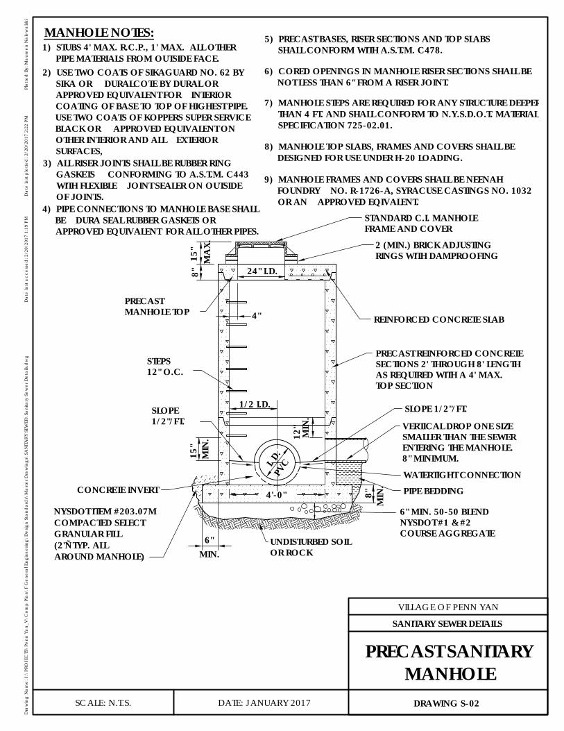
MIN.6"
MANHOLE NOTES:
15"
MIN
.
MIN
.8"
SLOPE 1/2"/FT.
OR ROCKUNDISTURBED SOIL
WATERTIGHT CONNECTION
8" MINIMUM.ENTERING THE MANHOLE.SMALLER THAN THE SEWERVERTICAL DROP ONE SIZE
PIPE BEDDING
NYSDOT #1 & #2 6" MIN. 50-50 BLEND
4'-0"
1/2"/FT.SLOPE
12"
MIN
.
1/2 I.D.
24" I.D.
4"MANHOLE TOPPRECAST
8"M
AX.
15"
FRAME AND COVERSTANDARD C.I. MANHOLE
RINGS WITH DAMPROOFING2 (MIN.) BRICK ADJUSTING
TOP SECTIONAS REQUIRED WITH A 4' MAX.SECTIONS 2' THROUGH 8' LENGTHPRECAST REINFORCED CONCRETE
REINFORCED CONCRETE SLAB
12" O.C.STEPS
PVCI. D
.
CONCRETE INVERT
COURSE AGGREGATE
NYSDOT ITEM #203.07MCOMPACTED SELECTGRANULAR FILL(2'± TYP. ALLAROUND MANHOLE)
1) STUBS 4' MAX. R.C.P., 1' MAX. ALL OTHERPIPE MATERIALS FROM OUTSIDE FACE.
2) USE TWO COATS OF SIKAGUARD NO. 62 BYSIKA OR DURALCOTE BY DURAL ORAPPROVED EQUIVALENT FOR INTERIORCOATING OF BASE TO TOP OF HIGHEST PIPE.USE TWO COATS OF KOPPERS SUPER SERVICEBLACK OR APPROVED EQUIVALENT ONOTHER INTERIOR AND ALL EXTERIORSURFACES,
3) ALL RISER JOINTS SHALL BE RUBBER RINGGASKETS CONFORMING TO A.S.T.M. C443WITH FLEXIBLE JOINT SEALER ON OUTSIDEOF JOINTS.
4) PIPE CONNECTIONS TO MANHOLE BASE SHALLBE DURA SEAL RUBBER GASKETS ORAPPROVED EQUIVALENT FOR ALL OTHER PIPES.
5) PRECAST BASES, RISER SECTIONS AND TOP SLABSSHALL CONFORM WITH A.S.T.M. C478.
6) CORED OPENINGS IN MANHOLE RISER SECTIONS SHALL BENOT LESS THAN 6" FROM A RISER JOINT.
7) MANHOLE STEPS ARE REQUIRED FOR ANY STRUCTURE DEEPERTHAN 4 FT. AND SHALL CONFORM TO N.Y.S.D.O.T. MATERIALSPECIFICATION 725-02.01.
8) MANHOLE TOP SLABS, FRAMES AND COVERS SHALL BEDESIGNED FOR USE UNDER H-20 LOADING.
9) MANHOLE FRAMES AND COVERS SHALL BE NEENAHFOUNDRY NO. R-1726-A, SYRACUSE CASTINGS NO. 1032OR AN APPROVED EQIVALENT.
DATE: JANUARY 2017
VILLAGE OF PENN YAN
Dra
win
g N
ame:
J:\
PRO
JEC
TS\P
enn
Yan_
V\C
omp
Plan
\F G
ener
al E
ngin
eerin
g\D
esig
n St
and
ard
s\M
aste
r Dra
win
gs\S
AN
ITARY
SEW
ER\S
anita
ry S
ewer
Det
ails.
dw
gD
ate
last
acc
esse
d: 2
/20/
2017
1:1
9 PM
Dat
e la
st p
lotte
d: 2
/20/
2017
2:2
2 PM
Plot
ted
By:
Mau
reen
Nal
ewal
ski
SCALE: N.T.S. DRAWING S-02
SANITARY SEWER DETAILS
PRECAST SANITARYMANHOLE
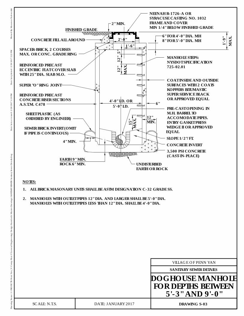
MANHOLES WITH OUTLET PIPES LESS THAN 12" DIA. SHALL BE 4'-0" DIA.
NOTES:
2.
1.
MANHOLES WITH OUTLET PIPES 12" DIA. AND LARGER SHALL BE 5'-0" DIA.
5'-0" I.D.
6" FOR 4'-0" DIA. MH8" FOR 5'-0" DIA. MH
OR APPROVED EQUAL4'-0" I.D. OR
3,500 PSI CONCRETE
2" MIN.
6"
ENTRY GASKET PRESSWEDGE II OR APPROVED
4" MIN.
ALL BRICK MASONARY UNITS SHALL BE ASTM DESIGNATION C-32 GRADE SS.
FRAME AND COVERSYRACUSE CASTING NO. 1032NEENAH R-1726-A OR
MA
X.1'
-9"
1'-6"
5"M
AX.
12"
12"
2'-0"
725-02.01NYSDOT SPECIFICATIONMANHOLE STEPS:
SUPER SERVICE BLACKKOPPERS BITUMASTICSURFACES WITH 2 COATSCOAT INSIDE AND OUTSIDE
ACCOMODATE PIPES.M.H. BARREL TOPRE-CAST OPENING IN
SLOPE 1/2"/FT.
(CAST-IN-PLACE)
MIN.12"
MA
X.15
"
EARTH OR ROCKUNDISTURBEDROCK 6" MIN.
EARTH 9" MIN.
ORDERED BY ENGINEER)SHEET PLASTIC (AS
MAX. OR CONC. GRADE RINGSPACER-BRICK, 2 COURSES
CONCRETE FILL ALL AROUND
WITH 25" DIA. SLAB M.O.ECCENTRIC FLAT COVER SLABREINFORCED PRECAST
A.S.T.M. C478CONCRETE RISER SECTIONSREINFORCED PRECAST
FINISHED GRADE
CONCRETE INVERT
EQUAL
MIN 1/4" BELOW FINISHED GRADE
SUPER "O" RING JOINT
SEWER BRICK INVERT (OMITIF PIPE IS CONTINUOUS)
DATE: JANUARY 2017
VILLAGE OF PENN YAN
Dra
win
g N
ame:
J:\
PRO
JEC
TS\P
enn
Yan_
V\C
omp
Plan
\F G
ener
al E
ngin
eerin
g\D
esig
n St
and
ard
s\M
aste
r Dra
win
gs\S
AN
ITARY
SEW
ER\S
anita
ry S
ewer
Det
ails.
dw
gD
ate
last
acc
esse
d: 2
/20/
2017
1:1
9 PM
Dat
e la
st p
lotte
d: 2
/20/
2017
2:2
2 PM
Plot
ted
By:
Mau
reen
Nal
ewal
ski
SCALE: N.T.S. DRAWING S-03
SANITARY SEWER DETAILS
DOGHOUSE MANHOLEFOR DEPTHS BETWEEN
5'-3" AND 9'-0"
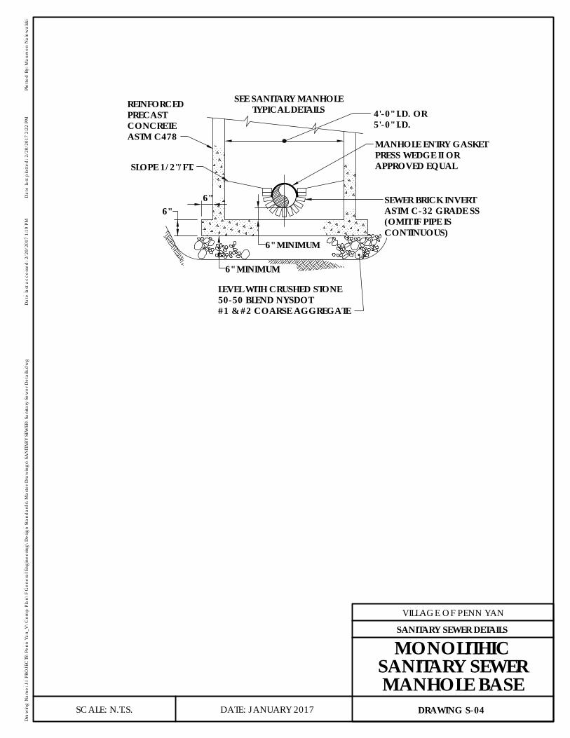
ASTM C478CONCRETE 5'-0" I.D.
4'-0" I.D. OR
CONTINUOUS)(OMIT IF PIPE ISASTM C-32 GRADE SSSEWER BRICK INVERT
APPROVED EQUALPRESS WEDGE II ORMANHOLE ENTRY GASKET
PRECASTREINFORCED
50-50 BLEND NYSDOTLEVEL WITH CRUSHED STONE
6" MINIMUM
TYPICAL DETAILSSEE SANITARY MANHOLE
6"6"
6" MINIMUM
SLOPE 1/2"/FT.
#1 & #2 COARSE AGGREGATE
DATE: JANUARY 2017
VILLAGE OF PENN YAN
Dra
win
g N
ame:
J:\
PRO
JEC
TS\P
enn
Yan_
V\C
omp
Plan
\F G
ener
al E
ngin
eerin
g\D
esig
n St
and
ard
s\M
aste
r Dra
win
gs\S
AN
ITARY
SEW
ER\S
anita
ry S
ewer
Det
ails.
dw
gD
ate
last
acc
esse
d: 2
/20/
2017
1:1
9 PM
Dat
e la
st p
lotte
d: 2
/20/
2017
2:2
2 PM
Plot
ted
By:
Mau
reen
Nal
ewal
ski
SCALE: N.T.S. DRAWING S-04
SANITARY SEWER DETAILS
MONOLITHICSANITARY SEWERMANHOLE BASE
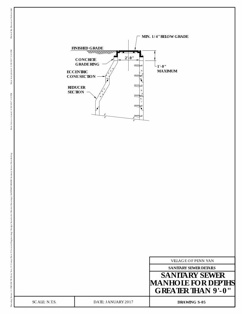
SECTIONREDUCER
CONE SECTIONECCENTRIC
GRADE RINGCONCRETE
MAXIMUM1'-0"
2'-0"
FINISHED GRADE
MIN. 1/4" BELOW GRADE
DATE: JANUARY 2017
VILLAGE OF PENN YAN
Dra
win
g N
ame:
J:\
PRO
JEC
TS\P
enn
Yan_
V\C
omp
Plan
\F G
ener
al E
ngin
eerin
g\D
esig
n St
and
ard
s\M
aste
r Dra
win
gs\S
AN
ITARY
SEW
ER\S
anita
ry S
ewer
Det
ails.
dw
gD
ate
last
acc
esse
d: 2
/20/
2017
1:1
9 PM
Dat
e la
st p
lotte
d: 2
/20/
2017
2:2
2 PM
Plot
ted
By:
Mau
reen
Nal
ewal
ski
SCALE: N.T.S. DRAWING S-05
SANITARY SEWER DETAILS
SANITARY SEWERMANHOLE FOR DEPTHS
GREATER THAN 9'-0"

2'-3"
3"
3"
#4 BAR
TYPICAL LIFT HOOP SECTION
6"4'-0" OR 5'-0" DIA.
AS SPECIFIEDSECTION
1'-0" ℄NON-SHRINK GROUTALL AROUND OUTSIDE
MANHOLE RISERASTM C-478
TOP REINFORCING #4 @ 12" E.W.BOTTOM REINFORCING #4 E.W. ASSHOWN ON PLAN
OUTSIDE SURFACES TO BEDAMP PROOFED BY MFR
℄℄
6" 6" 6" 6" 3"3"3"3"3"3" 6" 6"
3"3"
3"3"
6"6"
3"
2'-0" DIA.OPENINGTYPICAL HALF PLAN
LIFT HOOPPRECAST REINFORCED CONCRETECOVER SLAB SHAPED TO FITGROOVE END OF MANHOLE RISER
PRECAST REINFORCED CONCRETECOVER SLAB SHAPED TO FITGROOVE END OF MANHOLE RISER
LIFT HOOP#4 BARS2'-4" LONG
℄
DATE: JANUARY 2017
VILLAGE OF PENN YAN
Dra
win
g N
ame:
J:\
PRO
JEC
TS\P
enn
Yan_
V\C
omp
Plan
\F G
ener
al E
ngin
eerin
g\D
esig
n St
and
ard
s\M
aste
r Dra
win
gs\S
AN
ITARY
SEW
ER\S
anita
ry S
ewer
Det
ails.
dw
gD
ate
last
acc
esse
d: 2
/20/
2017
1:1
9 PM
Dat
e la
st p
lotte
d: 2
/20/
2017
2:2
2 PM
Plot
ted
By:
Mau
reen
Nal
ewal
ski
SCALE: N.T.S. DRAWING S-06
SANITARY SEWER DETAILS
CONCRETECOVER SLAB
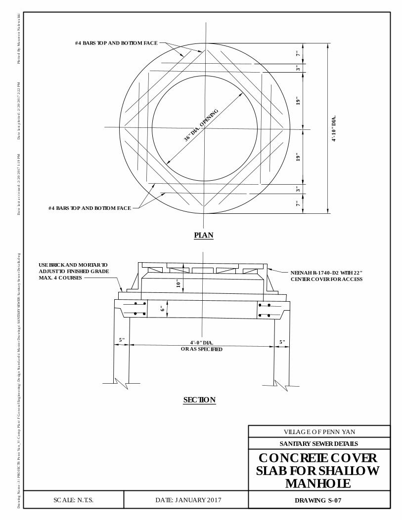
36" D
IA. OPE
NING
#4 BARS TOP AND BOTTOM FACE
#4 BARS TOP AND BOTTOM FACE
4'-1
0" D
IA.
7"3"
19"
19"
3"7"
PLAN
SECTION
USE BRICK AND MORTAR TOADJUST TO FINISHED GRADEMAX. 4 COURSES
NEENAH R-1740-D2 WITH 22"CENTER COVER FOR ACCESS
10"
6"
5" 4'-0" DIA.OR AS SPECIFIED
5"
DATE: JANUARY 2017
VILLAGE OF PENN YAN
Dra
win
g N
ame:
J:\
PRO
JEC
TS\P
enn
Yan_
V\C
omp
Plan
\F G
ener
al E
ngin
eerin
g\D
esig
n St
and
ard
s\M
aste
r Dra
win
gs\S
AN
ITARY
SEW
ER\S
anita
ry S
ewer
Det
ails.
dw
gD
ate
last
acc
esse
d: 2
/20/
2017
1:1
9 PM
Dat
e la
st p
lotte
d: 2
/20/
2017
2:2
2 PM
Plot
ted
By:
Mau
reen
Nal
ewal
ski
SCALE: N.T.S. DRAWING S-07
SANITARY SEWER DETAILS
CONCRETE COVERSLAB FOR SHALLOW
MANHOLE
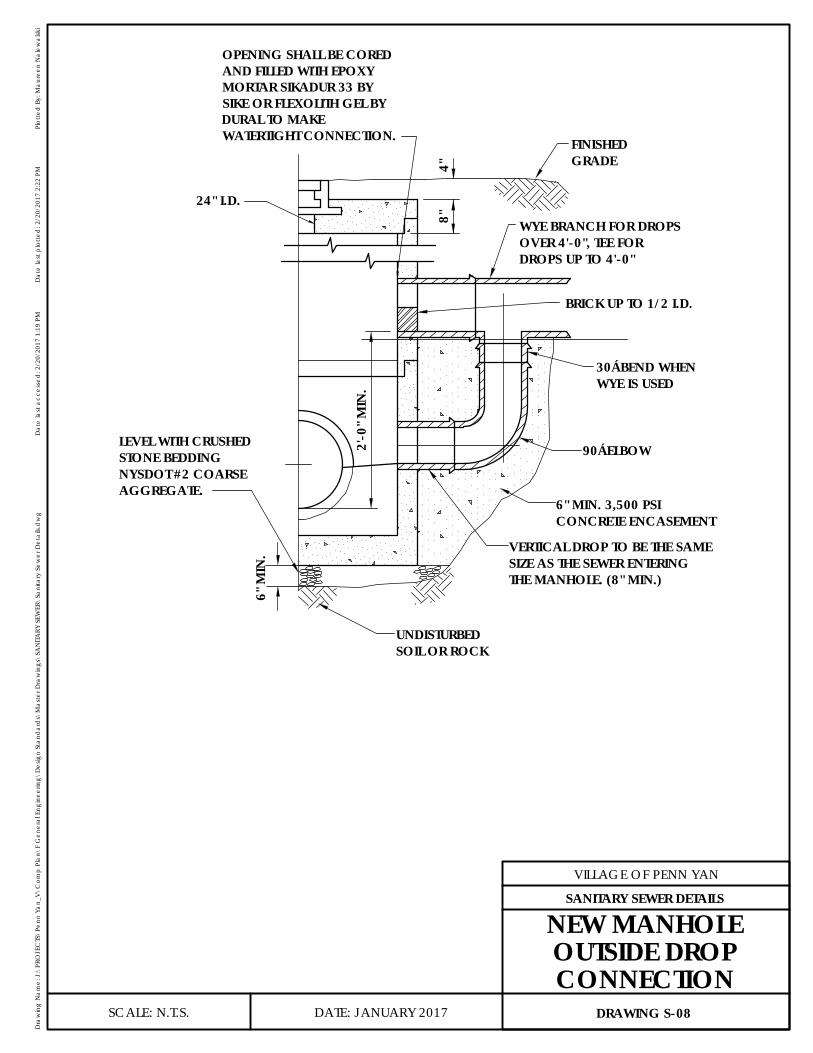
24" I.D.
2'-0
" MIN
.
SOIL OR ROCKUNDISTURBED
THE MANHOLE. (8" MIN.)SIZE AS THE SEWER ENTERINGVERTICAL DROP TO BE THE SAME
CONCRETE ENCASEMENT6" MIN. 3,500 PSI
90° ELBOW
WYE IS USED30° BEND WHEN
BRICK UP TO 1/2 I.D.
DROPS UP TO 4'-0"OVER 4'-0", TEE FORWYE BRANCH FOR DROPS
4"8"
GRADEFINISHED
STONE BEDDINGLEVEL WITH CRUSHED
NYSDOT #2 COARSEAGGREGATE.
6" M
IN.
OPENING SHALL BE COREDAND FILLED WITH EPOXYMORTAR SIKADUR 33 BYSIKE OR FLEXOLITH GEL BYDURAL TO MAKEWATERTIGHT CONNECTION.
DATE: JANUARY 2017
VILLAGE OF PENN YAN
Dra
win
g N
ame:
J:\
PRO
JEC
TS\P
enn
Yan_
V\C
omp
Plan
\F G
ener
al E
ngin
eerin
g\D
esig
n St
and
ard
s\M
aste
r Dra
win
gs\S
AN
ITARY
SEW
ER\S
anita
ry S
ewer
Det
ails.
dw
gD
ate
last
acc
esse
d: 2
/20/
2017
1:1
9 PM
Dat
e la
st p
lotte
d: 2
/20/
2017
2:2
2 PM
Plot
ted
By:
Mau
reen
Nal
ewal
ski
SCALE: N.T.S. DRAWING S-08
SANITARY SEWER DETAILS
NEW MANHOLEOUTSIDE DROPCONNECTION
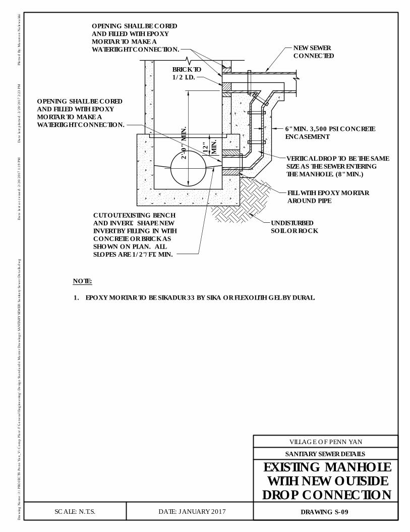
MIN
.12
"
2'-0
" M
IN. 6" MIN. 3,500 PSI CONCRETE
1/2 I.D.BRICK TO
SLOPES ARE 1/2"/FT. MIN.SHOWN ON PLAN. ALLCONCRETE OR BRICK ASINVERT BY FILLING IN WITHAND INVERT. SHAPE NEWCUT OUT EXISTING BENCH
OPENING SHALL BE COREDAND FILLED WITH EPOXYMORTAR TO MAKE AWATERTIGHT CONNECTION.
CONNECTEDNEW SEWER
AROUND PIPEFILL WITH EPOXY MORTAR
SOIL OR ROCKUNDISTURBED
THE MANHOLE. (8" MIN.)SIZE AS THE SEWER ENTERINGVERTICAL DROP TO BE THE SAME
NOTE:
EPOXY MORTAR TO BE SIKADUR 33 BY SIKA OR FLEXOLITH GEL BY DURAL.1.
ENCASEMENT
WATERTIGHT CONNECTION.MORTAR TO MAKE AAND FILLED WITH EPOXYOPENING SHALL BE CORED
DATE: JANUARY 2017
VILLAGE OF PENN YAN
Dra
win
g N
ame:
J:\
PRO
JEC
TS\P
enn
Yan_
V\C
omp
Plan
\F G
ener
al E
ngin
eerin
g\D
esig
n St
and
ard
s\M
aste
r Dra
win
gs\S
AN
ITARY
SEW
ER\S
anita
ry S
ewer
Det
ails.
dw
gD
ate
last
acc
esse
d: 2
/20/
2017
1:1
9 PM
Dat
e la
st p
lotte
d: 2
/20/
2017
2:2
3 PM
Plot
ted
By:
Mau
reen
Nal
ewal
ski
SCALE: N.T.S. DRAWING S-09
SANITARY SEWER DETAILS
EXISTING MANHOLEWITH NEW OUTSIDE
DROP CONNECTION
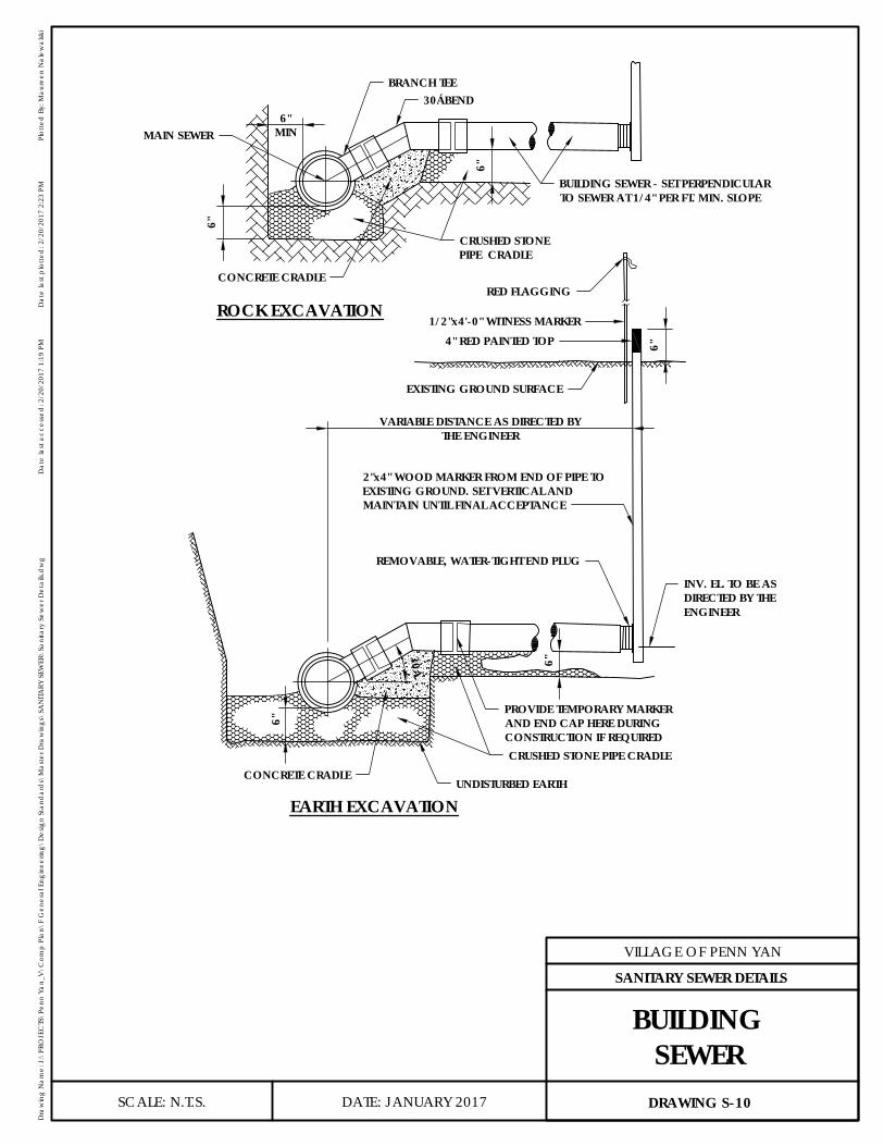
6"
30° 6"
VARIABLE DISTANCE AS DIRECTED BYTHE ENGINEER
6"
UNDISTURBED EARTH
CRUSHED STONE PIPE CRADLECONCRETE CRADLE
INV. EL. TO BE ASDIRECTED BY THEENGINEER
PROVIDE TEMPORARY MARKERAND END CAP HERE DURINGCONSTRUCTION IF REQUIRED
REMOVABLE, WATER-TIGHT END PLUG
2"x4" WOOD MARKER FROM END OF PIPE TOEXISTING GROUND. SET VERTICAL ANDMAINTAIN UNTIL FINAL ACCEPTANCE
EXISTING GROUND SURFACE
4" RED PAINTED TOP1/2"x4'-0" WITNESS MARKER
RED FLAGGING
EARTH EXCAVATION
6"MIN
6"
6"
MAIN SEWER
CONCRETE CRADLE
CRUSHED STONEPIPE CRADLE
BUILDING SEWER - SET PERPENDICULARTO SEWER AT 1/4" PER FT. MIN. SLOPE
BRANCH TEE30° BEND
ROCK EXCAVATION
DATE: JANUARY 2017
VILLAGE OF PENN YAN
Dra
win
g N
ame:
J:\
PRO
JEC
TS\P
enn
Yan_
V\C
omp
Plan
\F G
ener
al E
ngin
eerin
g\D
esig
n St
and
ard
s\M
aste
r Dra
win
gs\S
AN
ITARY
SEW
ER\S
anita
ry S
ewer
Det
ails.
dw
gD
ate
last
acc
esse
d: 2
/20/
2017
1:1
9 PM
Dat
e la
st p
lotte
d: 2
/20/
2017
2:2
3 PM
Plot
ted
By:
Mau
reen
Nal
ewal
ski
SCALE: N.T.S. DRAWING S-10
SANITARY SEWER DETAILS
BUILDINGSEWER

45° BEND
6"MIN.
6"
6"MIN.
45°
45°
BRANCH TEE
CONCRETEGRADLE
CRUSHED STONEPIPE GRADLE
MAIN SEWER
BUILD SEWER RISERVARIABLE LENGTH
6" M
IN
BUILDING SEWER, SET PERPENDICULAR TOSEWER AT 1/4" PER FT. MIN. SLOPE - FORCONTINUATION SEE BUILDING SEWER DETAIL
ROCK EXCAVATION
EARTH EXCAVATION
6"
CONCRETE CRADLE
CRUSHED STONEPIPE CRADLE
PROVIDE TEMPORARYMARKER AND ENDCAP HERE DURINGCONSTRUCTION IFREQUIRED
NOTE: INSTALL RISER IF REQUIRED DURINGCONSTRUCTION OF MAIN SEWER
UNDISTURBEDEARTH
DATE: JANUARY 2017
VILLAGE OF PENN YAN
Dra
win
g N
ame:
J:\
PRO
JEC
TS\P
enn
Yan_
V\C
omp
Plan
\F G
ener
al E
ngin
eerin
g\D
esig
n St
and
ard
s\M
aste
r Dra
win
gs\S
AN
ITARY
SEW
ER\S
anita
ry S
ewer
Det
ails.
dw
gD
ate
last
acc
esse
d: 2
/20/
2017
1:1
9 PM
Dat
e la
st p
lotte
d: 2
/20/
2017
2:2
3 PM
Plot
ted
By:
Mau
reen
Nal
ewal
ski
SCALE: N.T.S. DRAWING S-11
SANITARY SEWER DETAILS
BUILDINGSEWER RISER
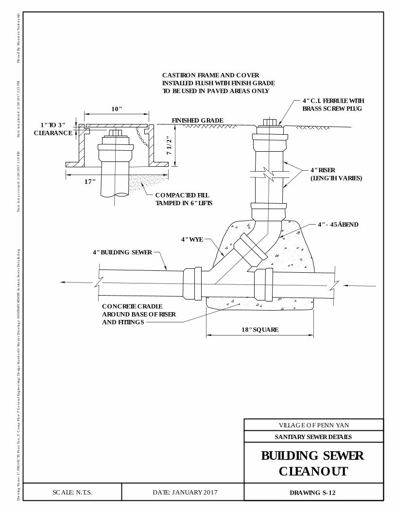
17"
7 1/
2"
10"
1" TO 3"CLEARANCE
COMPACTED FILLTAMPED IN 6" LIFTS
FINISHED GRADE
CAST IRON FRAME AND COVERINSTALLED FLUSH WITH FINISH GRADETO BE USED IN PAVED AREAS ONLY
4" C.I. FERRULE WITHBRASS SCREW PLUG
4" RISER(LENGTH VARIES)
4" - 45° BEND
4" WYE
4" BUILDING SEWER
CONCRETE CRADLEAROUND BASE OF RISERAND FITTINGS
18" SQUARE
DATE: JANUARY 2017
VILLAGE OF PENN YAN
Dra
win
g N
ame:
J:\
PRO
JEC
TS\P
enn
Yan_
V\C
omp
Plan
\F G
ener
al E
ngin
eerin
g\D
esig
n St
and
ard
s\M
aste
r Dra
win
gs\S
AN
ITARY
SEW
ER\S
anita
ry S
ewer
Det
ails.
dw
gD
ate
last
acc
esse
d: 2
/20/
2017
1:1
9 PM
Dat
e la
st p
lotte
d: 2
/20/
2017
2:2
3 PM
Plot
ted
By:
Mau
reen
Nal
ewal
ski
SCALE: N.T.S. DRAWING S-12
SANITARY SEWER DETAILS
BUILDING SEWERCLEANOUT

3'-0"
BREAKAWAY FLANGE
HYDRANT: KENNEDY K-81(RED)
VALVE BOX, SLIDING ORSCREW TYPE. INSTALL VERTICAL& CENTER OVER STEM
3 S.F. CONCRETEBACKING AGAINSTUNDISTURBED EARTH
6" D.I.ANCHOR PIPE
8"x8"x16" SOLIDCONCRETE BLDG. BLOCK
6" M.J. ANCHOR TEE6" GATE VALVE:MECHANICAL JOINT,RESILENT WEDGE OPEN LEFT(NON-RISING STEM)INSTALL LEVEL WITHSTAINLESS STEEL FASTENERS
NOTES:1. WRAP FITTINGS IN POLYETHYLENE FILM PRIOR TO PLACING CONCRETE THRUST BLOCKS.2. ALL FLANGES ON FIRE HYDRANT LEG SHALL BE MECHANICAL JOINT RESTRAINING TYPE OF
FLANGES.3. IN ROCK AREAS PROVIDE 6" MINIMUM DEPTH OF CRUSHED STONE CRADLE UNDER ALL PIPE
AND APPURTENANCES.4. ORIENTATION AND EXACT LOCATION TO BE DETERMINED BY ENGINEER.5. EXISTING GRADE AT HYDRANT LOCATION SHALL BE MODIFIED AS NECESSARY TO MAINTAIN
A MINIMUM OF 2" AND A MAXIMUM OF 6" BETWEEN GRADE AND THE BREAKAWAY FLANGEAT THE HYDRANT BARREL. THIS INCLUDES CUTTING OR FILLING AS NECESSARY.
3 S.F. CONCRETEBACKING AGAINSTUNDISTURBED EARTH
COVER TO BEMARKED "WATER"
VALVESTEM
OFFSET TO WATER MAIN5'-0" MIN,
WA
TER
MA
IN
4 C.F. #2CRUSHED STONEFOR DRAINAGE
5'-0
" CO
VER
5'-6
" BUR
Y LE
NG
TH
2" MIN AND 6" MAX. SEE NOTE 5.
DATE: JANUARY 2017
VILLAGE OF PENN YAN
Dra
win
g N
ame:
J:\
PRO
JEC
TS\P
enn
Yan_
V\C
omp
Plan
\F G
ener
al E
ngin
eerin
g\D
esig
n St
and
ard
s\M
aste
r Dra
win
gs\W
ATE
R\W
ater
Det
ails.
dw
gD
ate
last
acc
esse
d: 2
/20/
2017
2:1
0 PM
Dat
e la
st p
lotte
d: 2
/20/
2017
2:2
5 PM
Plot
ted
By:
Mau
reen
Nal
ewal
ski
SCALE: N.T.S. DRAWING W-01
WATER DETAILS
FIRE HYDRANTASSEMBLY
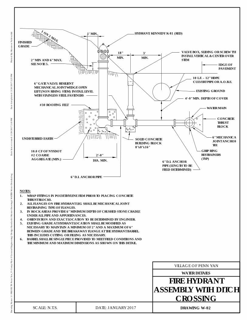
DIA. MIN.2'-0"
FIRE HYDRANT ASSEMBLY WITH DITCH CROSSING
3'
1' MIN.1 ON 2 MAX.
10.0 CF OF NYSDOT#2 COARSEAGGREGATE (MIN.)
UNDISTURBED EARTH
6" D.I. ANCHORPIPE (LENGTH TO BEFIELD DETERMINED)
6" MECHANICALJOINT ANCHORTEE
CONCRETETHRUSTBLOCK
WATER MAIN
4'-0" MIN. DEPTH OF COVER
EXISTING GROUND
10 L.F. - 12" HDPECULVERT PIPE OR A.O.B.E.
EDGE OFPAVEMENT
VALVE BOX, SLIDING OR SCREW TYPE.INSTALL VERTICAL & CENTER OVERSTEM
FINISHEDGRADE
#30 ROOFING FELT
6" D.I. ANCHOR PIPE
MIN.18"
MIN.
6" GATE VALVE: RESILIENTMECHANICAL JOINT WEDGE OPENLEFT (NON RISING STEM) INSTALL LEVELWITH STAINLESS STEEL FASTENERS
SOLID CONCRETEBUILDING BLOCK8"x8"x16"
2" MIN AND 6" MAX.SEE NOTE 5.
GRIP RINGRESTRAINERS(TYP)
NOTES:
HYDRANT: KENNEDY K-81 (RED)
1. WRAP FITTINGS IN POLYETHYLENE FILM PRIOR TO PLACING CONCRETE THRUST BLOCKS.
2. ALL FLANGES ON FIRE HYDRANT LEG SHALL BE MECHANICAL JOINTRESTRAINING TYPE OF FLANGES.
3. IN ROCK AREAS PROVIDE 6" MINIMUM DEPTH OF CRUSHED STONE CRADLEUNDER ALL PIPE AND APPURTENANCES.
4. ORIENTATION AND EXACT LOCATION TO BE DETERMINED BY ENGINEER.5. EXISTING GRADE AT HYDRANT LOCATION SHALL BE MODIFIED AS
NECESSARY TO MAINTAIN A MINIMUM OF 2" AND A MAXIMUM OF 6"BETWEEN GRADE AND THE BREAKAWAY FLANGE AT THE HYDRANT BARREL.THIS INCLUDES CUTTING OR FILLING AS NECESSARY.
6. BARREL SHALL BE SINGLE PIECE PROVIDED TO MEET FIELD CONDITIONS ANDTHE MINIMUM AND MAXIMUM DIMENSIONS AS SHOWN ON THIS DETAIL.
DATE: JANUARY 2017
VILLAGE OF PENN YAN
Dra
win
g N
ame:
J:\
PRO
JEC
TS\P
enn
Yan_
V\C
omp
Plan
\F G
ener
al E
ngin
eerin
g\D
esig
n St
and
ard
s\M
aste
r Dra
win
gs\W
ATE
R\W
ater
Det
ails.
dw
gD
ate
last
acc
esse
d: 2
/20/
2017
2:1
0 PM
Dat
e la
st p
lotte
d: 2
/20/
2017
2:2
5 PM
Plot
ted
By:
Mau
reen
Nal
ewal
ski
SCALE: N.T.S. DRAWING W-02
WATER DETAILS
FIRE HYDRANTASSEMBLY WITH DITCH
CROSSING
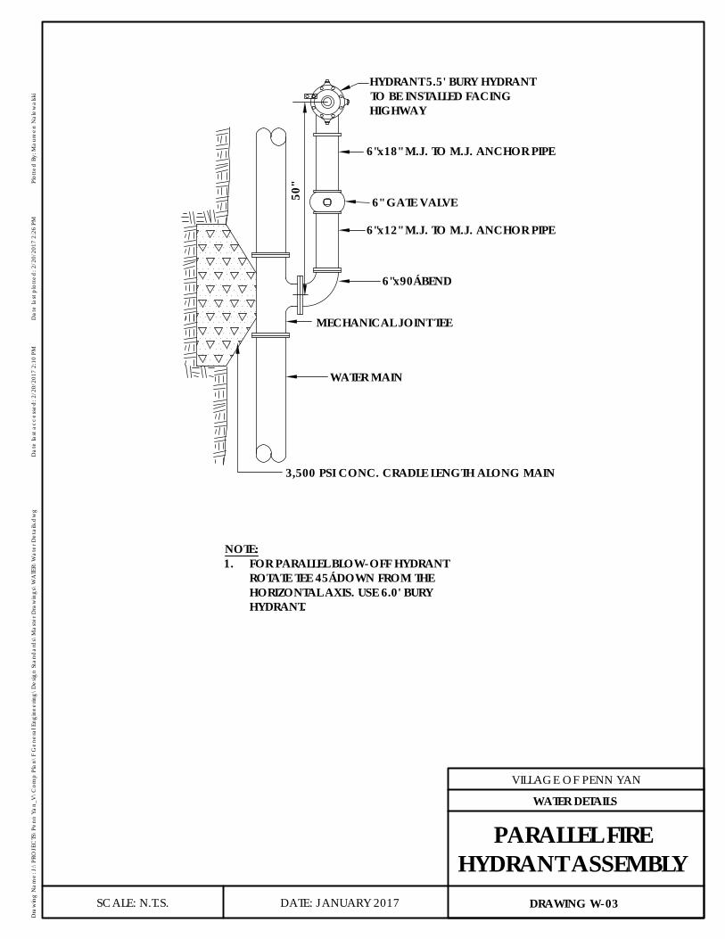
HYDRANT 5.5' BURY HYDRANTTO BE INSTALLED FACINGHIGHWAY
6"x18" M.J. TO M.J. ANCHOR PIPE
6" GATE VALVE
6"x12" M.J. TO M.J. ANCHOR PIPE
6"x90° BEND
MECHANICAL JOINT TEE
WATER MAIN
NOTE:1. FOR PARALLEL BLOW-OFF HYDRANT
ROTATE TEE 45° DOWN FROM THEHORIZONTAL AXIS. USE 6.0' BURYHYDRANT.
3,500 PSI CONC. CRADLE LENGTH ALONG MAIN
50"
DATE: JANUARY 2017
VILLAGE OF PENN YAN
Dra
win
g N
ame:
J:\
PRO
JEC
TS\P
enn
Yan_
V\C
omp
Plan
\F G
ener
al E
ngin
eerin
g\D
esig
n St
and
ard
s\M
aste
r Dra
win
gs\W
ATE
R\W
ater
Det
ails.
dw
gD
ate
last
acc
esse
d: 2
/20/
2017
2:1
0 PM
Dat
e la
st p
lotte
d: 2
/20/
2017
2:2
6 PM
Plot
ted
By:
Mau
reen
Nal
ewal
ski
SCALE: N.T.S. DRAWING W-03
WATER DETAILS
PARALLEL FIREHYDRANT ASSEMBLY
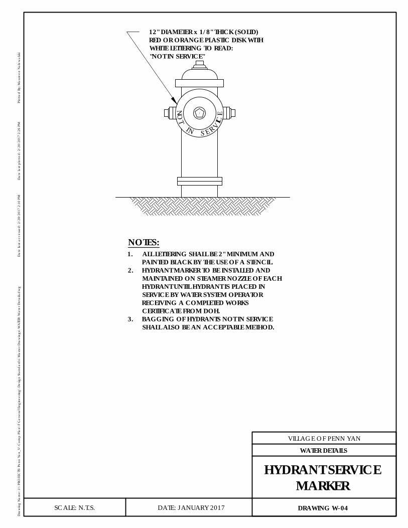
NOT
S E R VIC
E
IN
NOTES:1. ALL LETTERING SHALL BE 2" MINIMUM AND
PAINTED BLACK BY THE USE OF A STENCIL.2. HYDRANT MARKER TO BE INSTALLED AND
MAINTAINED ON STEAMER NOZZLE OF EACHHYDRANT UNTIL HYDRANT IS PLACED INSERVICE BY WATER SYSTEM OPERATORRECEIVING A COMPLETED WORKSCERTIFICATE FROM DOH.
3. BAGGING OF HYDRANTS NOT IN SERVICESHALL ALSO BE AN ACCEPTABLE METHOD.
12" DIAMETER x 1/8" THICK (SOLID)RED OR ORANGE PLASTIC DISK WITHWHITE LETTERING TO READ:"NOT IN SERVICE"
DATE: JANUARY 2017
VILLAGE OF PENN YAN
Dra
win
g N
ame:
J:\
PRO
JEC
TS\P
enn
Yan_
V\C
omp
Plan
\F G
ener
al E
ngin
eerin
g\D
esig
n St
and
ard
s\M
aste
r Dra
win
gs\W
ATE
R\W
ater
Det
ails.
dw
gD
ate
last
acc
esse
d: 2
/20/
2017
2:1
0 PM
Dat
e la
st p
lotte
d: 2
/20/
2017
2:2
6 PM
Plot
ted
By:
Mau
reen
Nal
ewal
ski
SCALE: N.T.S. DRAWING W-04
WATER DETAILS
HYDRANT SERVICEMARKER

UNDISTURBED EARTH
5'-0
" MIN
. CO
VER
COVER TO BEMARKED "WATER"
2 PIECE VALVE BOXSLIDING OR SCREW TYPEINSTALL VERTICAL &CENTER OVER STEM
GATE VALVE SHALL BERESILIENT SEAT (OPEN LEFT)NON-RISING STEM, WITHSTAINLESS STEEL FASTENERS
8"x8"x16" SOLIDCONCRETE BLDG. BLOCK
NOTE:
1. THE VALVE BOX SHALL BE CENTERED ON THE VALVE AND BACKFILLEDSO THAT IT SETS ON COMPACTED FILL, NOT RESTING ON THE VALVEHOUSING.
DATE: JANUARY 2017
VILLAGE OF PENN YAN
Dra
win
g N
ame:
J:\
PRO
JEC
TS\P
enn
Yan_
V\C
omp
Plan
\F G
ener
al E
ngin
eerin
g\D
esig
n St
and
ard
s\M
aste
r Dra
win
gs\W
ATE
R\W
ater
Det
ails.
dw
gD
ate
last
acc
esse
d: 2
/20/
2017
2:1
0 PM
Dat
e la
st p
lotte
d: 2
/20/
2017
2:2
6 PM
Plot
ted
By:
Mau
reen
Nal
ewal
ski
SCALE: N.T.S. DRAWING W-05
WATER DETAILS
LINE VALVE
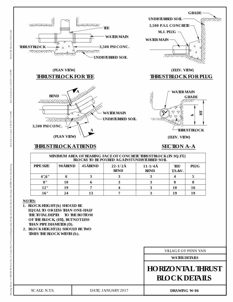
THRUST BLOCK FOR TEE
1937132416"103471912"84
33
33
63
106
8"4",6"
BLOCKS TO BE POURED AGAINST UNDISTURBED SOILMINIMUM AREA OF BEARING FACE OF CONCRETE THRUST BLOCK (IN SQ.FT.)
45° BEND90° BENDPIPE SIZE
THRUST BLOCK FOR PLUG
3,500 P.S.I. CONCRETE
GRADE
M.J. PLUG
WATER MAIN
(ELEV. VIEW)
PLUG
168
19
5
TEE
WATER MAIN
3,500 PSI CONC.THRUST BLOCK
UNDISTURBED SOIL
(PLAN VIEW)
WATER MAIN
THRUST BLOCK
GRADE
(ELEV. VIEW)
A
A
WATER MAIN
BEND
3,500 PSI CONC.
UNDISTURBED SOIL
UNDISTURBED SOIL
(PLAN VIEW)
b
D h HT
THRUST BLOCK AT BENDS SECTION A-A
22-1/2°BEND
11-1/4°BEND
TEE/T.S.&V.
NOTES:1. BLOCK HEIGHT (h) SHOULD BE
EQUAL TO OR LESS THAN ONE-HALFTHE TOTAL DEPTH TO THE BOTTOMOF THE BLOCK, (HT), BUT NOT LESSTHAN PIPE DIAMETER (D).
2. BLOCK HEIGHT (h) SHOULD BE TWOTIMES THE BLOCK WIDTH (b).
DATE: JANUARY 2017
VILLAGE OF PENN YAN
Dra
win
g N
ame:
J:\
PRO
JEC
TS\P
enn
Yan_
V\C
omp
Plan
\F G
ener
al E
ngin
eerin
g\D
esig
n St
and
ard
s\M
aste
r Dra
win
gs\W
ATE
R\W
ater
Det
ails.
dw
gD
ate
last
acc
esse
d: 2
/20/
2017
2:1
0 PM
Dat
e la
st p
lotte
d: 2
/20/
2017
2:2
6 PM
Plot
ted
By:
Mau
reen
Nal
ewal
ski
SCALE: N.T.S. DRAWING W-06
WATER DETAILS
HORIZONTAL THRUSTBLOCK DETAILS
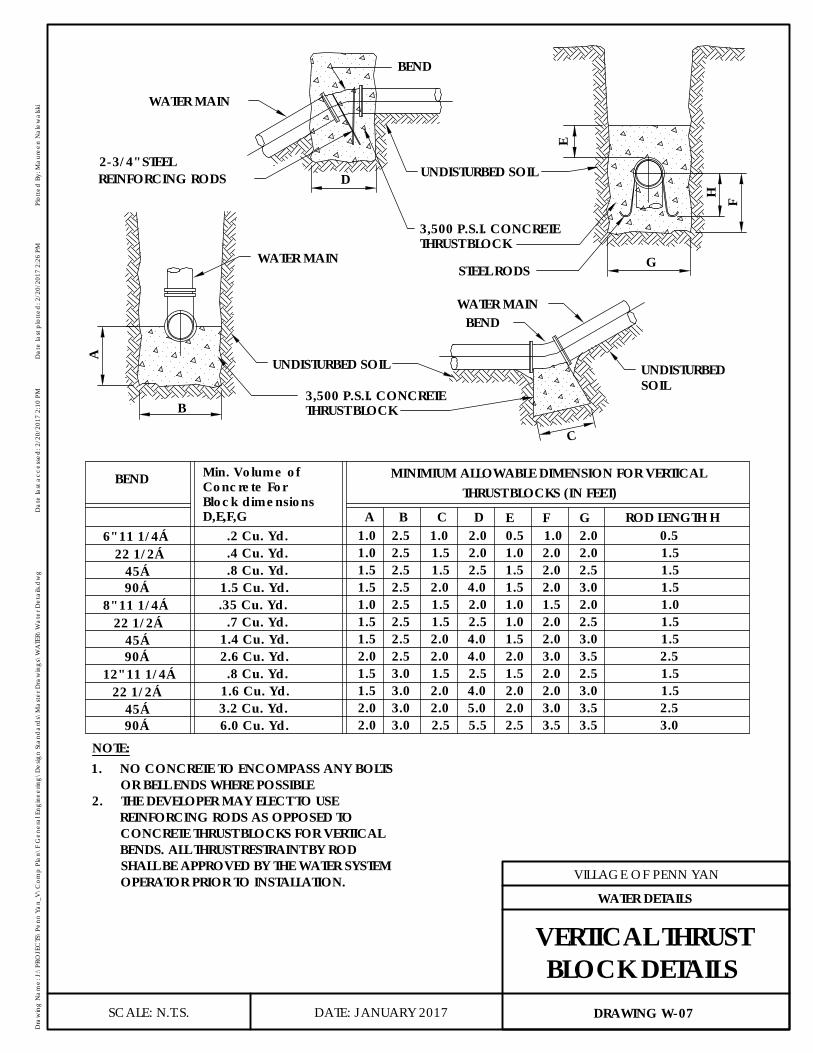
0.52.01.02.51.0
MINIMIUM ALLOWABLE DIMENSION FOR VERTICAL
ROD LENGTH HEDCBA
C
BENDWATER MAIN
UNDISTURBED SOIL
3,500 P.S.I. CONCRETETHRUST BLOCK
WATER MAIN
UNDISTURBEDSOIL
A
B
G
F
UNDISTURBED SOIL
WATER MAIN
BEND
E
H
2-3/4" STEELREINFORCING RODS
STEEL RODS
D
6" 11 1/4°22 1/2°
45°90°
8" 11 1/4°22 1/2°
45°90°
12" 11 1/4°22 1/2°
45°90°
.2 Cu. Yd.
.4 Cu. Yd.
.8 Cu. Yd.1.5 Cu. Yd..35 Cu. Yd.
.7 Cu. Yd.1.4 Cu. Yd.2.6 Cu. Yd..8 Cu. Yd.
1.6 Cu. Yd.3.2 Cu. Yd.6.0 Cu. Yd.
BEND
F G1.0 0.5
1.01.51.51.01.51.52.01.51.52.02.0
2.52.52.5
2.52.52.52.5
3.03.03.03.0
1.51.5
1.51.52.02.01.52.02.02.5
2.02.5
2.0
4.0
4.0
5.55.0
2.5
4.02.5
4.02.0
1.01.51.51.01.01.52.01.52.02.02.5
2.02.02.01.52.02.03.02.02.03.03.5
2.02.02.53.02.02.53.03.52.53.03.53.5 3.0
2.51.51.5
1.51.5
2.5
1.51.51.51.0
Min. Volume ofConcrete ForBlock dimensionsD,E,F,G
THRUST BLOCKS (IN FEET)
NOTE:
THRUST BLOCK3,500 P.S.I. CONCRETE
1. NO CONCRETE TO ENCOMPASS ANY BOLTSOR BELL ENDS WHERE POSSIBLE
2. THE DEVELOPER MAY ELECT TO USEREINFORCING RODS AS OPPOSED TOCONCRETE THRUST BLOCKS FOR VERTICALBENDS. ALL THRUST RESTRAINT BY RODSHALL BE APPROVED BY THE WATER SYSTEMOPERATOR PRIOR TO INSTALLATION.
DATE: JANUARY 2017
VILLAGE OF PENN YAN
Dra
win
g N
ame:
J:\
PRO
JEC
TS\P
enn
Yan_
V\C
omp
Plan
\F G
ener
al E
ngin
eerin
g\D
esig
n St
and
ard
s\M
aste
r Dra
win
gs\W
ATE
R\W
ater
Det
ails.
dw
gD
ate
last
acc
esse
d: 2
/20/
2017
2:1
0 PM
Dat
e la
st p
lotte
d: 2
/20/
2017
2:2
6 PM
Plot
ted
By:
Mau
reen
Nal
ewal
ski
SCALE: N.T.S. DRAWING W-07
WATER DETAILS
VERTICAL THRUSTBLOCK DETAILS
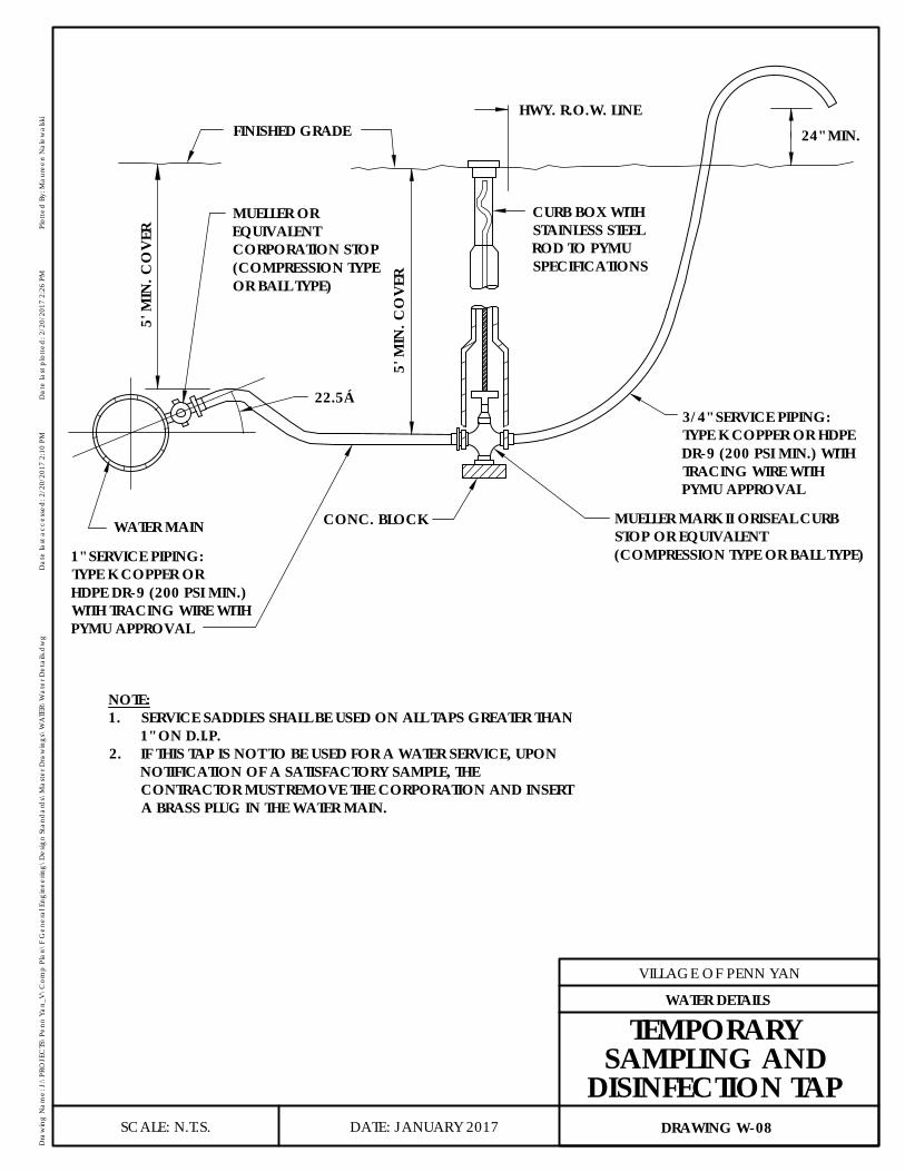
24" MIN.HWY. R.O.W. LINE
22.5°
5' M
IN. C
OVE
R
5' M
IN. C
OVE
R
FINISHED GRADE
CONC. BLOCK
WATER MAIN
MUELLER OREQUIVALENTCORPORATION STOP(COMPRESSION TYPEOR BALL TYPE)
CURB BOX WITHSTAINLESS STEELROD TO PYMUSPECIFICATIONS
3/4" SERVICE PIPING:TYPE K COPPER OR HDPEDR-9 (200 PSI MIN.) WITHTRACING WIRE WITHPYMU APPROVAL
1" SERVICE PIPING:TYPE K COPPER ORHDPE DR-9 (200 PSI MIN.)WITH TRACING WIRE WITHPYMU APPROVAL
NOTE:1. SERVICE SADDLES SHALL BE USED ON ALL TAPS GREATER THAN
1" ON D.I.P.2. IF THIS TAP IS NOT TO BE USED FOR A WATER SERVICE, UPON
NOTIFICATION OF A SATISFACTORY SAMPLE, THECONTRACTOR MUST REMOVE THE CORPORATION AND INSERTA BRASS PLUG IN THE WATER MAIN.
MUELLER MARK II ORISEAL CURBSTOP OR EQUIVALENT(COMPRESSION TYPE OR BALL TYPE)
DATE: JANUARY 2017
VILLAGE OF PENN YAN
Dra
win
g N
ame:
J:\
PRO
JEC
TS\P
enn
Yan_
V\C
omp
Plan
\F G
ener
al E
ngin
eerin
g\D
esig
n St
and
ard
s\M
aste
r Dra
win
gs\W
ATE
R\W
ater
Det
ails.
dw
gD
ate
last
acc
esse
d: 2
/20/
2017
2:1
0 PM
Dat
e la
st p
lotte
d: 2
/20/
2017
2:2
6 PM
Plot
ted
By:
Mau
reen
Nal
ewal
ski
SCALE: N.T.S. DRAWING W-08
WATER DETAILS
TEMPORARYSAMPLING AND
DISINFECTION TAP
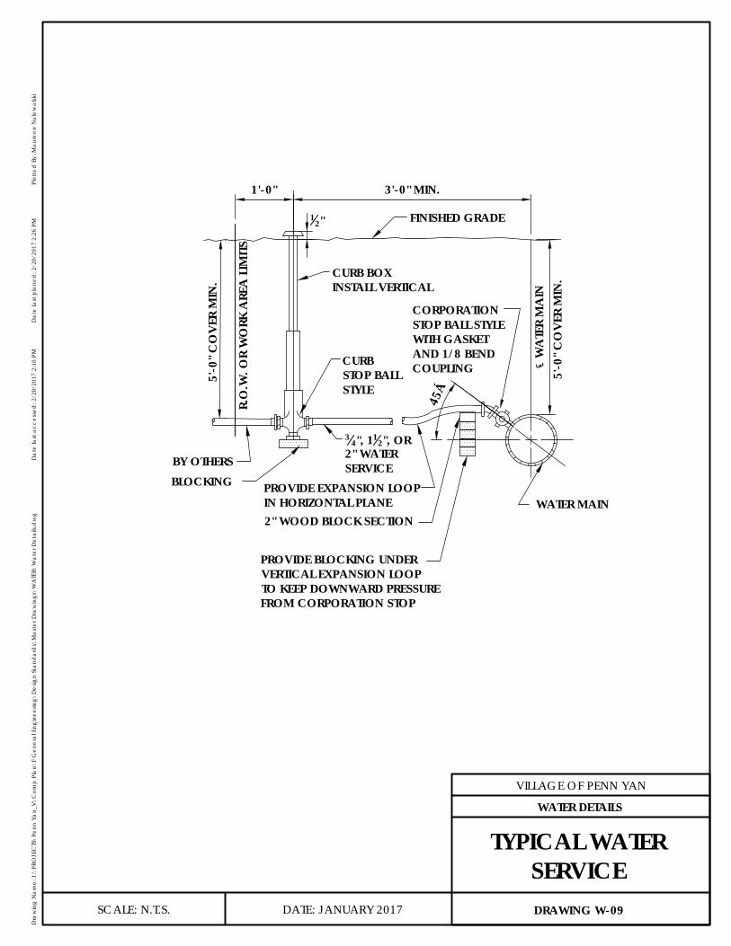
FINISHED GRADE
BLOCKING
WATER MAIN
45°
12"
CURB BOXINSTALL VERTICAL
CURBSTOP BALLSTYLE
CORPORATIONSTOP BALL STYLEWITH GASKETAND 1/8 BENDCOUPLING ℄
WA
TER
MA
IN5'
-0" C
OVE
R M
IN.
34", 11
2", OR2" WATERSERVICEBY OTHERS
5'-0
" CO
VER
MIN
.
1'-0" 3'-0" MIN.
R.O
.W. O
R W
ORK
ARE
A L
IMITS
PROVIDE EXPANSION LOOPIN HORIZONTAL PLANE2" WOOD BLOCK SECTION
PROVIDE BLOCKING UNDERVERTICAL EXPANSION LOOPTO KEEP DOWNWARD PRESSUREFROM CORPORATION STOP
DATE: JANUARY 2017
VILLAGE OF PENN YAN
Dra
win
g N
ame:
J:\
PRO
JEC
TS\P
enn
Yan_
V\C
omp
Plan
\F G
ener
al E
ngin
eerin
g\D
esig
n St
and
ard
s\M
aste
r Dra
win
gs\W
ATE
R\W
ater
Det
ails.
dw
gD
ate
last
acc
esse
d: 2
/20/
2017
2:1
0 PM
Dat
e la
st p
lotte
d: 2
/20/
2017
2:2
6 PM
Plot
ted
By:
Mau
reen
Nal
ewal
ski
SCALE: N.T.S. DRAWING W-09
WATER DETAILS
TYPICAL WATERSERVICE
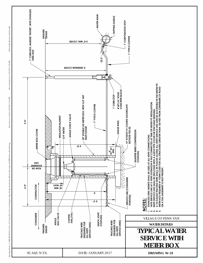
DATE: JANUARY 2017
VILLAGE OF PENN YAN
Dra
win
g N
ame:
J:\
PRO
JEC
TS\P
enn
Yan_
V\C
omp
Plan
\F G
ener
al E
ngin
eerin
g\D
esig
n St
and
ard
s\M
aste
r Dra
win
gs\W
ATE
R\W
ater
Det
ails.
dw
gD
ate
last
acc
esse
d: 2
/20/
2017
2:1
0 PM
Dat
e la
st p
lotte
d: 2
/20/
2017
2:2
6 PM
Plot
ted
By:
Mau
reen
Nal
ewal
ski
SCALE: N.T.S. DRAWING W-10
WATER DETAILS
TYPICAL WATERSERVICE WITHMETER BOX
10"
6" MIN
18" MIN24" MAX
5' 6"
5'
22.5
°
4' 8"
SERV
ICE
LIN
E (C
ON
SUM
ERPO
RTIO
N)
CO
PPER
PIPE
(TYP
)
FIN
ISHE
DG
RADE
AN
GLE
BALL
VA
LVE
QUA
RTER
BEN
D C
OM
PRES
SIO
NC
OUP
LIN
G
12" N
YSDO
T #1
CO
URSE
AG
GRE
GA
TESE
CTIO
N 7
03-0
2
20" D
OUB
LE L
ID M
ETER
BO
X, W
ITH 3
/4" M
IPIN
LET/
OUT
LET
1" C
URB
STO
P
AN
GLE
CHE
CK
VALV
E
3/4"
MET
ER
1" C
URB
BOX,
MA
RKED
"WA
TER"
, WIT
H ST
AIN
LESS
STEE
L RO
D
5' MINIMUM COVER
5-0" MIN. COVER
WA
TER
MA
IN
TAPP
ING
SA
DD
LE
1" C
ORP
ORA
TIO
N S
TOP
4"x8
"x16
" SO
LID
CO
NC
RETE
BLO
CK
FIN
ISHE
DG
RAD
E
ROW OREASEMENT
LINE
5' 0
"
TRA
CIN
G W
IRE
(REQ
UIRE
D FO
RA
LL H
DPE
SERV
ICE
LIN
ES)
QUI
CK
JOIN
TC
OUP
LIN
G
GRA
DE R
ING
3' 0
"
MET
ER B
OX
CO
VER
INSU
LATIO
N B
LAN
KET
NO
TES:
CO
NSU
MER
CO
NTR
AC
TOR
1.ST
AIN
LESS
STE
EL IN
SERT
S SH
ALL
BE
USED
AT A
LL H
DPE
CO
NN
ECTIO
NS.
2.TA
PE S
ERVI
CE
LIN
E A
T 5' H
DPE
EXTE
NSI
ON
IF N
OT C
ON
NEC
TED
AT T
IME
OR
MET
ER P
IT IN
STA
LLA
TIO
N.
3.HD
PE S
ERVI
CE
LIN
E SH
ALL
BE
ENC
LOSE
D W
ITH A
SLE
EVE
PIPE
CO
VER
OR
FIN
E SA
ND
BEDD
ING
.4.
A 1
0-G
AUG
E TR
AC
ING
WIR
E SH
ALL
BE
PLA
CED
ALO
NG
ALL
HDP
E SE
RVIC
E LI
NE
AN
D BE
AC
CES
SIBL
E IN
THE
MET
ER P
IT.
5.M
ETER
BO
X RE
QUI
RED
BY TO
WN
CO
DE F
OR
ALL
STR
UCTU
RES
GRE
ATE
R TH
AN
150
FEE
T FRO
M C
ENTE
RLIN
E O
F RO
AD
OR
A F
ULL
BASE
MEN
T IS
NO
T PRE
SEN
T.
1" TY
PE K
CO
PPER
1" T
YPE
K C
OPP
ER
TRA
CIN
G W
IRE
(REQ
UIRE
D FO
RA
LL H
DPE
SERV
ICE
LIN
ES)
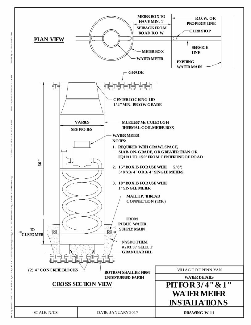
CROSS SECTION VIEW
TYPICAL PIT FOR 3/4" AND 1"
(2) 4" CONCRETE BLOCKS
MUELLER/McCULLOUGHTHERMAL-COIL METER BOX
WATER METER
CENTER LOCKING LID
66"
FROMPUBLIC WATERSUPPLY MAIN
BOTTOM SHALL BE FIRMUNDISTURBED EARTH
MALE I.P. THREADCONNECTION (TYP.)
GRADE
PLAN VIEW
WATER METER
CURB STOP
SERVICELINE
EXISTINGWATER MAIN
R.O.W. ORPROPERTY LINE
METER BOX
METER BOX TOHAVE MIN. 1'
SETBACK FROMROAD R.O.W.
VARIES
1/4" MIN. BELOW GRADE
2. 15" BOX IS FOR USE WITH: 5/8",5/8"x3/4" OR 3/4" SINGLE METERS
3. 18" BOX IS FOR USE WITH:1" SINGLE METER
1. REQUIRED WITH CRAWL SPACE,SLAB-ON-GRADE, OR GREATER THAN OREQUAL TO 150' FROM CENTERLINE OF ROAD
TOCUSTOMER
NYSDOT ITEM#203.07 SELECTGRANULAR FILL
SEE NOTES
NOTES:
DATE: JANUARY 2017
VILLAGE OF PENN YAN
Dra
win
g N
ame:
J:\
PRO
JEC
TS\P
enn
Yan_
V\C
omp
Plan
\F G
ener
al E
ngin
eerin
g\D
esig
n St
and
ard
s\M
aste
r Dra
win
gs\W
ATE
R\W
ater
Det
ails.
dw
gD
ate
last
acc
esse
d: 2
/20/
2017
2:1
0 PM
Dat
e la
st p
lotte
d: 2
/20/
2017
2:2
6 PM
Plot
ted
By:
Mau
reen
Nal
ewal
ski
SCALE: N.T.S. DRAWING W-11
WATER DETAILS
PIT FOR 3/4" & 1"WATER METER
INSTALLATIONS
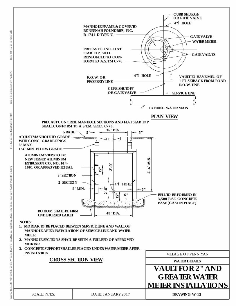
VAULT TO HAVE MIN. OF1 FT. SETBACK FROM ROADR.O.W. LINE
EXISTING WATER MAIN
CURB SHUTOFFOR GATE VALVE
4"Ø HOLER.O.W. ORPROPERTY LINE
GATE VALVEWATER METER
GATE VALVES
MANHOLE FRAME & COVER TOBE NEENAH FOUNDRIES, INC.R-1741-D TYPE "C"
4"Ø HOLEOR GATE VALVECURB SHUTOFF
SERVICE LINE
PRECAST CONC. FLATSLAB TOP, STEELREINFORCED TO CON-FORM TO A.S.T.M C-76
PLAN VIEW
CROSS SECTION VIEW
ADJUST MANHOLE TO GRADEWITH CONC. GRADE RINGS8" MAX.
ALUMINUM STEPS TO BENEW JERSEY ALUMINUMEXTRUSION CO. NO. F14-1001 OR APPROVED EQUAL
3' SECTION
2' SECTION 4"Ø HOLE
48" DIA.
6"12"
5" MIN.
4'-6
" MIN
.
BELL TO BE FORMED IN3,500 P.S.I. CONCRETEBASE (CAST IN PLACE)
BOTTOM SHALL BE FIRMUNDISTURBED EARTH
5"
2'-0
"3'
-0"
12"
36" DIA. 5"5"
PRECAST CONCRETE MANHOLE SECTIONS AND FLAT SLAB TOPSHALL CONFORM TO A.S.T.M. SPEC. C-76.
NOTES:
GRADE
1/4" MIN. BELOW GRADE
1. MORTAR TO BE PLACED BETWEEN SERVICE LINE AND WALL OFMANHOLE AFTER INSTALLATION OF SERVICE LINE AND WATERMETER.
2. MANHOLE SECTIONS SHALL BE SET IN A FULL BED OF APPROVEDMORTAR.
3. CONCRETE SUPPORT SHALL BE PLACED UNDER WATER METER AFTERINSTALLATION.
DATE: JANUARY 2017
VILLAGE OF PENN YAN
Dra
win
g N
ame:
J:\
PRO
JEC
TS\P
enn
Yan_
V\C
omp
Plan
\F G
ener
al E
ngin
eerin
g\D
esig
n St
and
ard
s\M
aste
r Dra
win
gs\W
ATE
R\W
ater
Det
ails.
dw
gD
ate
last
acc
esse
d: 2
/20/
2017
2:1
0 PM
Dat
e la
st p
lotte
d: 2
/20/
2017
2:2
6 PM
Plot
ted
By:
Mau
reen
Nal
ewal
ski
SCALE: N.T.S. DRAWING W-12
WATER DETAILS
VAULT FOR 2" ANDGREATER WATER
METER INSTALLATIONS
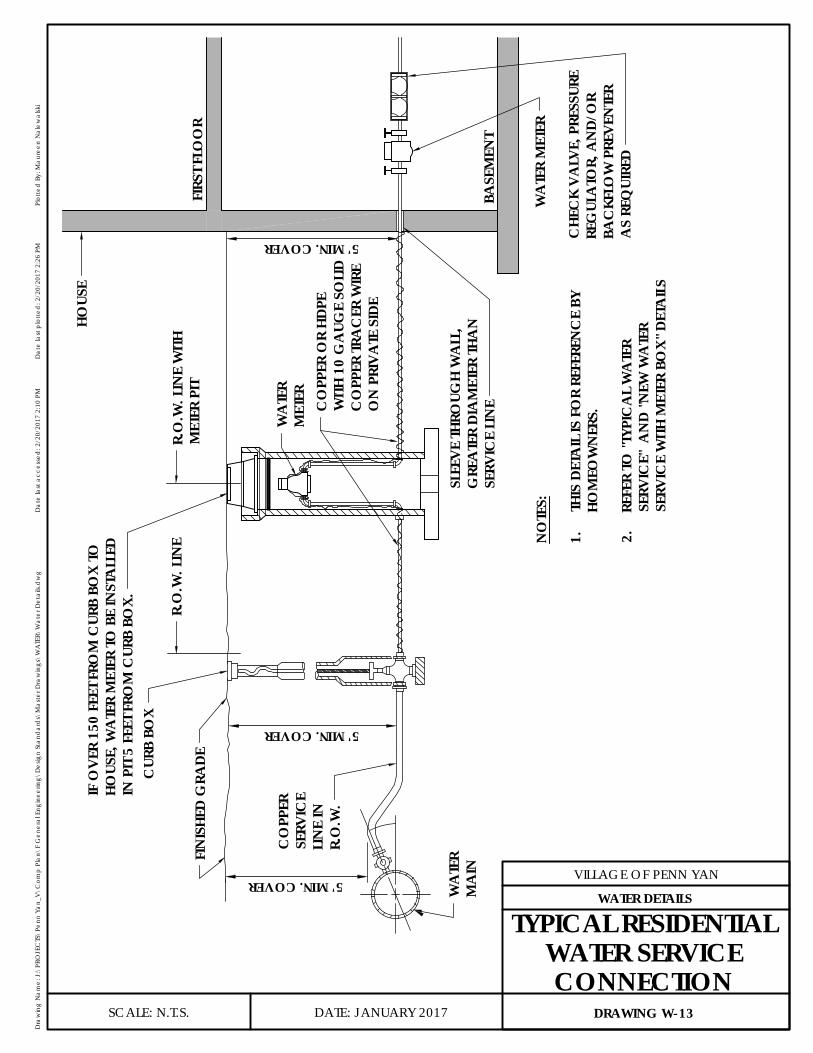
R.O
.W. L
INE
FIN
ISHE
D G
RADE
5' MIN. COVER
CO
PPER
SERV
ICE
LIN
E IN
R.O
.W.
WA
TER
MA
IN
5' MIN. COVER
HOUS
E
5' MIN. COVER
CUR
B BO
X
IF O
VER
150
FEET
FRO
M C
URB
BOX
TOHO
USE,
WA
TER
MET
ER TO
BE
INST
ALL
EDIN
PIT
5 FE
ET F
ROM
CUR
B BO
X.
WA
TER
MET
ER
WA
TER
MET
ER
FIRS
T FL
OO
R
BASE
MEN
T
SLEE
VE TH
ROUG
H W
ALL
,G
REA
TER
DIA
MET
ER T
HAN
SERV
ICE
LIN
E
NO
TES:
1.TH
IS D
ETA
IL IS
FO
R RE
FERE
NC
E BY
HOM
EOW
NER
S.
2.RE
FER
TO "T
YPIC
AL
WA
TER
SERV
ICE"
AN
D "N
EW W
ATE
RSE
RVIC
E W
ITH M
ETER
BO
X" D
ETA
ILS
R.O
.W. L
INE
WIT
HM
ETER
PIT
CHE
CK
VA
LVE,
PRE
SSUR
ERE
GUL
ATO
R, A
ND
/OR
BAC
KFLO
W P
REV
ENTE
RA
S RE
QUI
RED
CO
PPER
OR
HDPE
WITH
10
GA
UGE
SOLI
DC
OPP
ER T
RAC
ER W
IRE
ON
PRI
VA
TE S
IDE
DATE: JANUARY 2017
VILLAGE OF PENN YAN
Dra
win
g N
ame:
J:\
PRO
JEC
TS\P
enn
Yan_
V\C
omp
Plan
\F G
ener
al E
ngin
eerin
g\D
esig
n St
and
ard
s\M
aste
r Dra
win
gs\W
ATE
R\W
ater
Det
ails.
dw
gD
ate
last
acc
esse
d: 2
/20/
2017
2:1
0 PM
Dat
e la
st p
lotte
d: 2
/20/
2017
2:2
6 PM
Plot
ted
By:
Mau
reen
Nal
ewal
ski
SCALE: N.T.S. DRAWING W-13
WATER DETAILS
TYPICAL RESIDENTIALWATER SERVICECONNECTION

1" WATERSERVICE
3/4" METER WITH INLET ANDOUTLET COUPLINGS
FROMPUBLIC WATERSUPPLY MAIN
CHECK VALVE, PRESSUREREGULATOR, AND/OR BACKFLOWPREVENTER AS REQUIRED
TO RESIDENTIALPLUMBING
1"x3/4" STOPAND WATER VALVE
3/4" X "Z" STOPAND WATER VALVE
HOSE BIB AS REQUIRED
PRESSURE REDUCING VALVEAS REQUIRED
EXPANSION TANK AS REQUIREDNOTES:1. WATER METERS ARE NOT TO BE INSTALLED ON INCORRECT
PLUMBING PROVISIONS OR WITHIN CRAWL SPACE LOCATIONS.2. STOP AND WATER VALVE TO BE INSTALLED BEFORE AND
AFTER WATER METER. IF A BACKFLOW PREVENTER IS REQUIRED, IT SHALL IMMEDIATELY FOLLOW THE WATER METER BEFORE ANY SIDE CONNECTION.
3. REFER TO E-14 FOR GROUNDING.
"Z"= RESIDENTIALPLUMBING SIZE
DATE: JANUARY 2017
VILLAGE OF PENN YAN
Dra
win
g N
ame:
J:\
PRO
JEC
TS\P
enn
Yan_
V\C
omp
Plan
\F G
ener
al E
ngin
eerin
g\D
esig
n St
and
ard
s\M
aste
r Dra
win
gs\W
ATE
R\W
ater
Det
ails.
dw
gD
ate
last
acc
esse
d: 2
/20/
2017
2:1
0 PM
Dat
e la
st p
lotte
d: 2
/20/
2017
2:2
6 PM
Plot
ted
By:
Mau
reen
Nal
ewal
ski
SCALE: N.T.S. DRAWING W-14
WATER DETAILS
TYPICAL RESIDENTIALINSIDE METER
INSTALLATION DETAIL
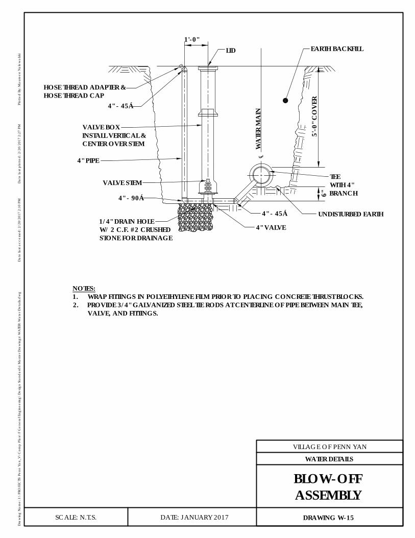
UNDISTURBED EARTH
5'-0
" CO
VER
WA
TER
MA
IN
EARTH BACKFILLLID
6"
HOSE THREAD ADAPTER &HOSE THREAD CAP
4" - 45°
VALVE BOXINSTALL VERTICAL &CENTER OVER STEM
4" PIPE
VALVE STEM
4" - 90°
1/4" DRAIN HOLEW/ 2 C.F. #2 CRUSHEDSTONE FOR DRAINAGE
4" VALVE
4" - 45°
TEEWITH 4"BRANCH
1'-0"
NOTES:1. WRAP FITTINGS IN POLYETHYLENE FILM PRIOR TO PLACING CONCRETE THRUST BLOCKS.2. PROVIDE 3/4" GALVANIZED STEEL TIE RODS AT CENTERLINE OF PIPE BETWEEN MAIN TEE,
VALVE, AND FITTINGS.
℄
DATE: JANUARY 2017
VILLAGE OF PENN YAN
Dra
win
g N
ame:
J:\
PRO
JEC
TS\P
enn
Yan_
V\C
omp
Plan
\F G
ener
al E
ngin
eerin
g\D
esig
n St
and
ard
s\M
aste
r Dra
win
gs\W
ATE
R\W
ater
Det
ails.
dw
gD
ate
last
acc
esse
d: 2
/20/
2017
2:1
0 PM
Dat
e la
st p
lotte
d: 2
/20/
2017
2:2
7 PM
Plot
ted
By:
Mau
reen
Nal
ewal
ski
SCALE: N.T.S. DRAWING W-15
WATER DETAILS
BLOW-OFFASSEMBLY
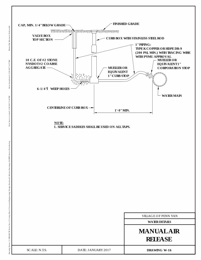
CURB BOX WITH STAINLESS STEEL ROD
FINISHED GRADE
WATER MAIN
1'-0" MIN.CENTERLINE OF CURB BOX
6-1/4"Ø WEEP HOLES
VALVE BOXTOP SECTION
CAP, MIN. 1/4" BELOW GRADE
NYSDOT #2 COARSE10 C.F. OF #2 STONE
AGGREGATE
1" PIPING:TYPE K COPPER OR HDPE DR-9(200 PSI, MIN.) WITH TRACING WIREWITH PYMU APPROVAL
NOTE:1. SERVICE SADDLES SHALL BE USED ON ALL TAPS.
MUELLER OREQUIVALENT 1"CORPORATION STOPMUELLER OR
EQUIVALENT1" CURB STOP
DATE: JANUARY 2017
VILLAGE OF PENN YAN
Dra
win
g N
ame:
J:\
PRO
JEC
TS\P
enn
Yan_
V\C
omp
Plan
\F G
ener
al E
ngin
eerin
g\D
esig
n St
and
ard
s\M
aste
r Dra
win
gs\W
ATE
R\W
ater
Det
ails.
dw
gD
ate
last
acc
esse
d: 2
/20/
2017
2:1
0 PM
Dat
e la
st p
lotte
d: 2
/20/
2017
2:2
7 PM
Plot
ted
By:
Mau
reen
Nal
ewal
ski
SCALE: N.T.S. DRAWING W-16
WATER DETAILS
MANUAL AIRRELEASE
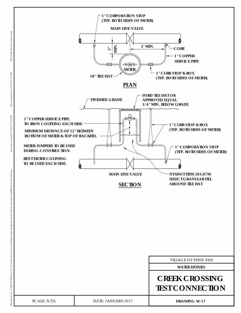
M
M
MAIN LINE VALVE
CORE
1" CURB STOP & BOX
1" COPPER
18" TILE HATMETER
MIN
. 2' MIN.
METER JUMPERS TO BE USEDDURING CONSTRUCTION.
BENT METER COUPLINGTO BE USED EACH SIDE.
1" COPPER SERVICE PIPETO IRON COUPLING EACH SIDE
MINIMUM DISTANCE OF 12" BETWEENBOTTOM OF METER & TOP OF BACKFILL
MAIN LINE VALVE
FINISHED GRADEFORD TILE HAT OR
PLAN
SECTION
SERVICE PIPE
(TYP. BOTH SIDES OF METER)
1" CORPORATION STOP(TYP. BOTH SIDES OF METER)
3"
APPROVED EQUAL
(TYP. BOTH SIDES OF METER)1" CORPORATION STOP
1" CURB STOP & BOX(TYP. BOTH SIDES OF METER)
AROUND TILE HAT
NYSDOT ITEM 203.07MSELECT GRANULAR FILL
1/4" MIN. BELOW GRADE
DATE: JANUARY 2017
VILLAGE OF PENN YAN
Dra
win
g N
ame:
J:\
PRO
JEC
TS\P
enn
Yan_
V\C
omp
Plan
\F G
ener
al E
ngin
eerin
g\D
esig
n St
and
ard
s\M
aste
r Dra
win
gs\W
ATE
R\W
ater
Det
ails.
dw
gD
ate
last
acc
esse
d: 2
/20/
2017
2:1
0 PM
Dat
e la
st p
lotte
d: 2
/20/
2017
2:2
7 PM
Plot
ted
By:
Mau
reen
Nal
ewal
ski
SCALE: N.T.S. DRAWING W-17
WATER DETAILS
CREEK CROSSINGTEST CONNECTION
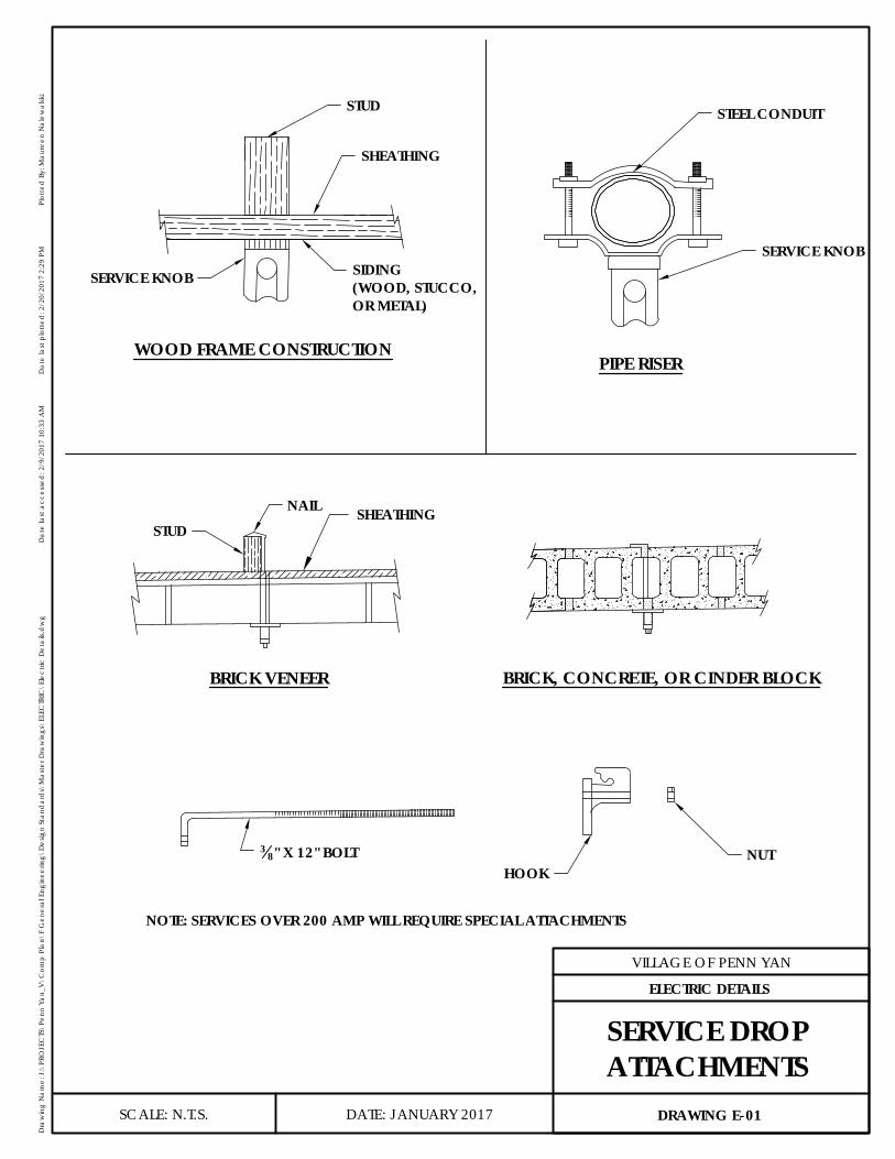
E-01STUD
SHEATHING
SERVICE KNOB SIDING(WOOD, STUCCO,OR METAL)
WOOD FRAME CONSTRUCTION
STEEL CONDUIT
SERVICE KNOB
PIPE RISER
STUDNAIL SHEATHING
BRICK VENEER BRICK, CONCRETE, OR CINDER BLOCK
NUTHOOK
38" X 12" BOLT
NOTE: SERVICES OVER 200 AMP WILL REQUIRE SPECIAL ATTACHMENTS
DATE: JANUARY 2017
VILLAGE OF PENN YAN
Dra
win
g N
ame:
J:\
PRO
JEC
TS\P
enn
Yan_
V\C
omp
Plan
\F G
ener
al E
ngin
eerin
g\D
esig
n St
and
ard
s\M
aste
r Dra
win
gs\E
LEC
TRIC
\Ele
ctric
Det
ails.
dw
gD
ate
last
acc
esse
d: 2
/9/2
017
10:3
3 A
MD
ate
last
plo
tted
: 2/2
0/20
17 2
:29
PMPl
otte
d B
y: M
aure
en N
alew
alsk
i
SCALE: N.T.S. DRAWING E-01
ELECTRIC DETAILS
SERVICE DROPATTACHMENTS
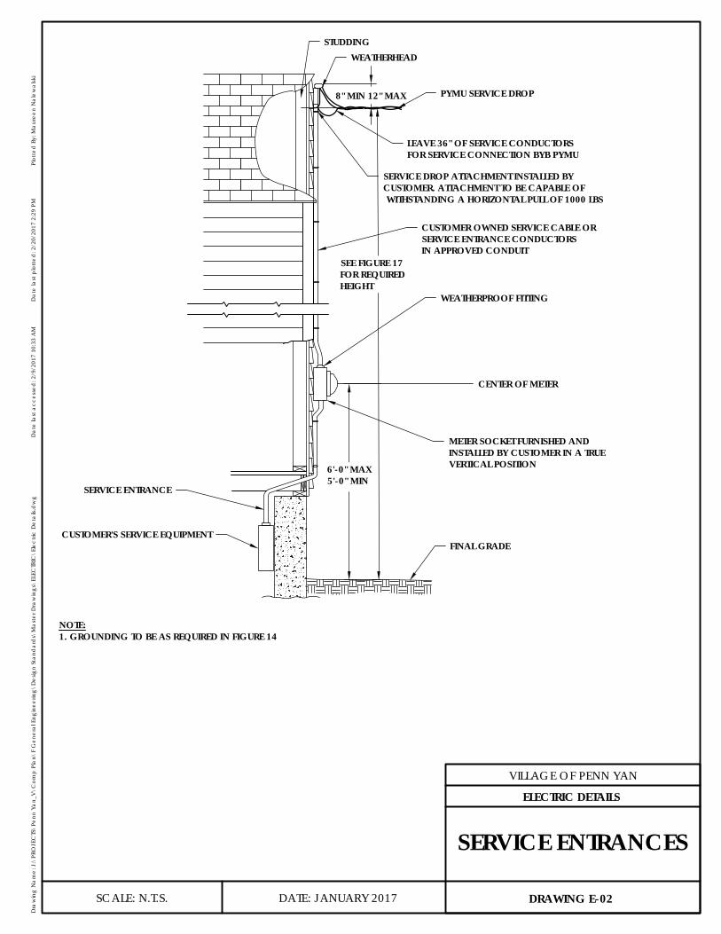
FINAL GRADECUSTOMER'S SERVICE EQUIPMENT
SERVICE ENTRANCE
METER SOCKET FURNISHED ANDINSTALLED BY CUSTOMER IN A TRUEVERTICAL POSITION
CENTER OF METER
WEATHERPROOF FITTING
CUSTOMER OWNED SERVICE CABLE ORSERVICE ENTRANCE CONDUCTORSIN APPROVED CONDUIT
PYMU SERVICE DROP
LEAVE 36" OF SERVICE CONDUCTORSFOR SERVICE CONNECTION BYB PYMU
WEATHERHEADSTUDDING
8" MIN 12" MAX
-SEE FIGURE 17FOR REQUIREDHEIGHT
-6'-0" MAX5'-0" MIN
SERVICE DROP ATTACHMENT INSTALLED BYCUSTOMER. ATTACHMENT TO BE CAPABLE OF WITHSTANDING A HORIZONTAL PULL OF 1000 LBS
NOTE:1. GROUNDING TO BE AS REQUIRED IN FIGURE 14
DATE: JANUARY 2017
VILLAGE OF PENN YAN
Dra
win
g N
ame:
J:\
PRO
JEC
TS\P
enn
Yan_
V\C
omp
Plan
\F G
ener
al E
ngin
eerin
g\D
esig
n St
and
ard
s\M
aste
r Dra
win
gs\E
LEC
TRIC
\Ele
ctric
Det
ails.
dw
gD
ate
last
acc
esse
d: 2
/9/2
017
10:3
3 A
MD
ate
last
plo
tted
: 2/2
0/20
17 2
:29
PMPl
otte
d B
y: M
aure
en N
alew
alsk
i
SCALE: N.T.S. DRAWING E-02
ELECTRIC DETAILS
SERVICE ENTRANCES
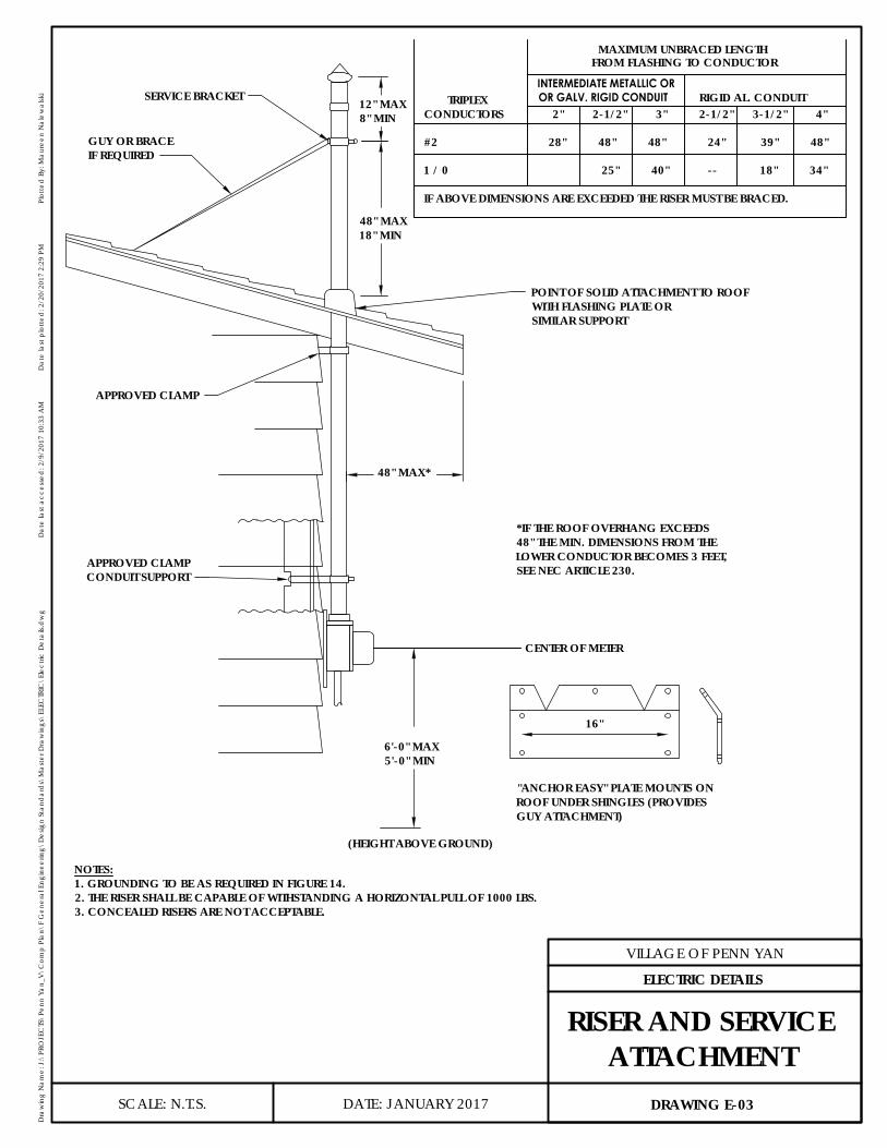
GUY OR BRACEIF REQUIRED
APPROVED CLAMPCONDUIT SUPPORT
POINT OF SOLID ATTACHMENT TO ROOFWITH FLASHING PLATE ORSIMILAR SUPPORT
SERVICE BRACKET
APPROVED CLAMP
*IF THE ROOF OVERHANG EXCEEDS48" THE MIN. DIMENSIONS FROM THELOWER CONDUCTOR BECOMES 3 FEET,SEE NEC ARTICLE 230.
NOTES:1. GROUNDING TO BE AS REQUIRED IN FIGURE 14.2. THE RISER SHALL BE CAPABLE OF WITHSTANDING A HORIZONTAL PULL OF 1000 LBS.3. CONCEALED RISERS ARE NOT ACCEPTABLE.
16"
"ANCHOR EASY" PLATE MOUNTS ONROOF UNDER SHINGLES (PROVIDESGUY ATTACHMENT)
-
-
12" MAX8" MIN
48" MAX18" MIN
-48" MAX*
-6'-0" MAX5'-0" MIN
(HEIGHT ABOVE GROUND)
CENTER OF METER
MAXIMUM UNBRACED LENGTH
INTERMEDIATE METALLIC OR TRIPLEXCONDUCTORS 2" 2-1/2" 3" 2-1/2" 3-1/2" 4"
#2 28" 48" 48" 24" 39" 48"
1 / 0 25" 40" -- 18" 34"
IF ABOVE DIMENSIONS ARE EXCEEDED THE RISER MUST BE BRACED.
OR GALV. RIGID CONDUIT RIGID AL. CONDUIT
FROM FLASHING TO CONDUCTOR
DATE: JANUARY 2017
VILLAGE OF PENN YAN
Dra
win
g N
ame:
J:\
PRO
JEC
TS\P
enn
Yan_
V\C
omp
Plan
\F G
ener
al E
ngin
eerin
g\D
esig
n St
and
ard
s\M
aste
r Dra
win
gs\E
LEC
TRIC
\Ele
ctric
Det
ails.
dw
gD
ate
last
acc
esse
d: 2
/9/2
017
10:3
3 A
MD
ate
last
plo
tted
: 2/2
0/20
17 2
:29
PMPl
otte
d B
y: M
aure
en N
alew
alsk
i
SCALE: N.T.S. DRAWING E-03
ELECTRIC DETAILS
RISER AND SERVICEATTACHMENT

NOTES:1. POLE TO BE TREATED IN ACCORDANCE WITH EEI SPECIFICATIONS TD100 OR TD 102. MINIMUN POLE CLASS 7. SEE SECTION IV, OF
THE PENN YAN MUNICIPAL UTILITIES SPECIFICATIONS FOR THE INSTALLATION OF ELECTRIC SERVICES AND METERS FOR CLEARANCE.2. POLE MUST BE ADEQUATELY SUPPORTED TO WITHSTAND 1000LBS HORIZONTAL PULL AT THE POINT OF SERVICE DROP ATTACHMENT.3. INSTALLATION ALSO APPROVED FOR UNDERGROUND USE WITH SERVICE ENTRANCE SIMILAR TO DIAGRAM VIII.4. INSTALLATION SHALL MEET REQUIREMENTS OF THE NATIONAL ELECTRICAL CODE.
CONTINUOUS GROUNDINGCONDUCTORS #4 COPPER MINIMUM
FINAL GRADE
GUY AS REQUIRED
UTILITY SERVICE DROP
CUSTOMER SERVICEEQUIPMENT INWEATHERPROOF ENCLOSURE
34" TREATED EXTERIOR PLYWOOD
SECURELY FASTENED TO SUPPORTS
-LENGTH AS REQUIRED
2'-6"
2' TO 2'-6"
-POLE 6"MIN DEPTH 4"x4"x6" TREATED TIMBERS
3" MIN
3" MIN
58" x 8" GROUND ROOTS
(COPPER END)
DATE: JANUARY 2017
VILLAGE OF PENN YAN
Dra
win
g N
ame:
J:\
PRO
JEC
TS\P
enn
Yan_
V\C
omp
Plan
\F G
ener
al E
ngin
eerin
g\D
esig
n St
and
ard
s\M
aste
r Dra
win
gs\E
LEC
TRIC
\Ele
ctric
Det
ails.
dw
gD
ate
last
acc
esse
d: 2
/9/2
017
10:3
3 A
MD
ate
last
plo
tted
: 2/2
0/20
17 2
:30
PMPl
otte
d B
y: M
aure
en N
alew
alsk
i
SCALE: N.T.S. DRAWING E-04
ELECTRIC DETAILS
MULTIPLE METERINSTALLATION
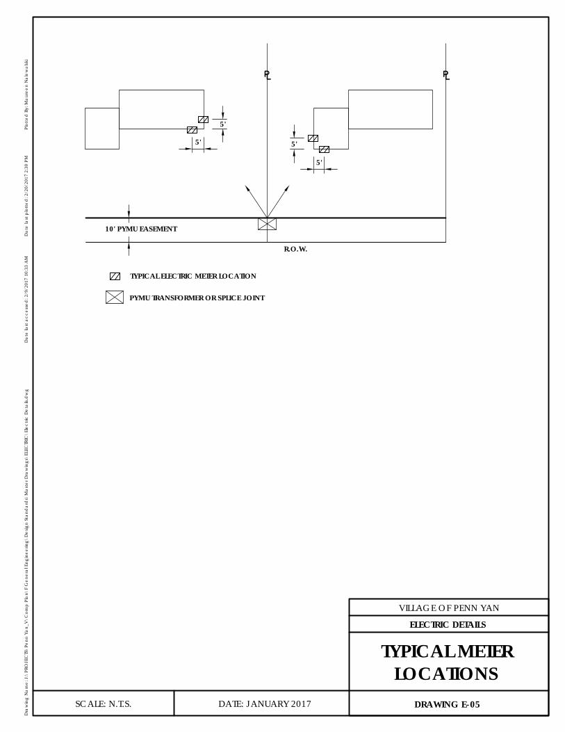
PYMU TRANSFORMER OR SPLICE JOINT
TYPICAL ELECTRIC METER LOCATION
0.3636
5'
5'
5'
5'
10' PYMU EASEMENT
R.O.W.
⅊ ⅊
DATE: JANUARY 2017
VILLAGE OF PENN YAN
Dra
win
g N
ame:
J:\
PRO
JEC
TS\P
enn
Yan_
V\C
omp
Plan
\F G
ener
al E
ngin
eerin
g\D
esig
n St
and
ard
s\M
aste
r Dra
win
gs\E
LEC
TRIC
\Ele
ctric
Det
ails.
dw
gD
ate
last
acc
esse
d: 2
/9/2
017
10:3
3 A
MD
ate
last
plo
tted
: 2/2
0/20
17 2
:30
PMPl
otte
d B
y: M
aure
en N
alew
alsk
i
SCALE: N.T.S. DRAWING E-05
ELECTRIC DETAILS
TYPICAL METERLOCATIONS
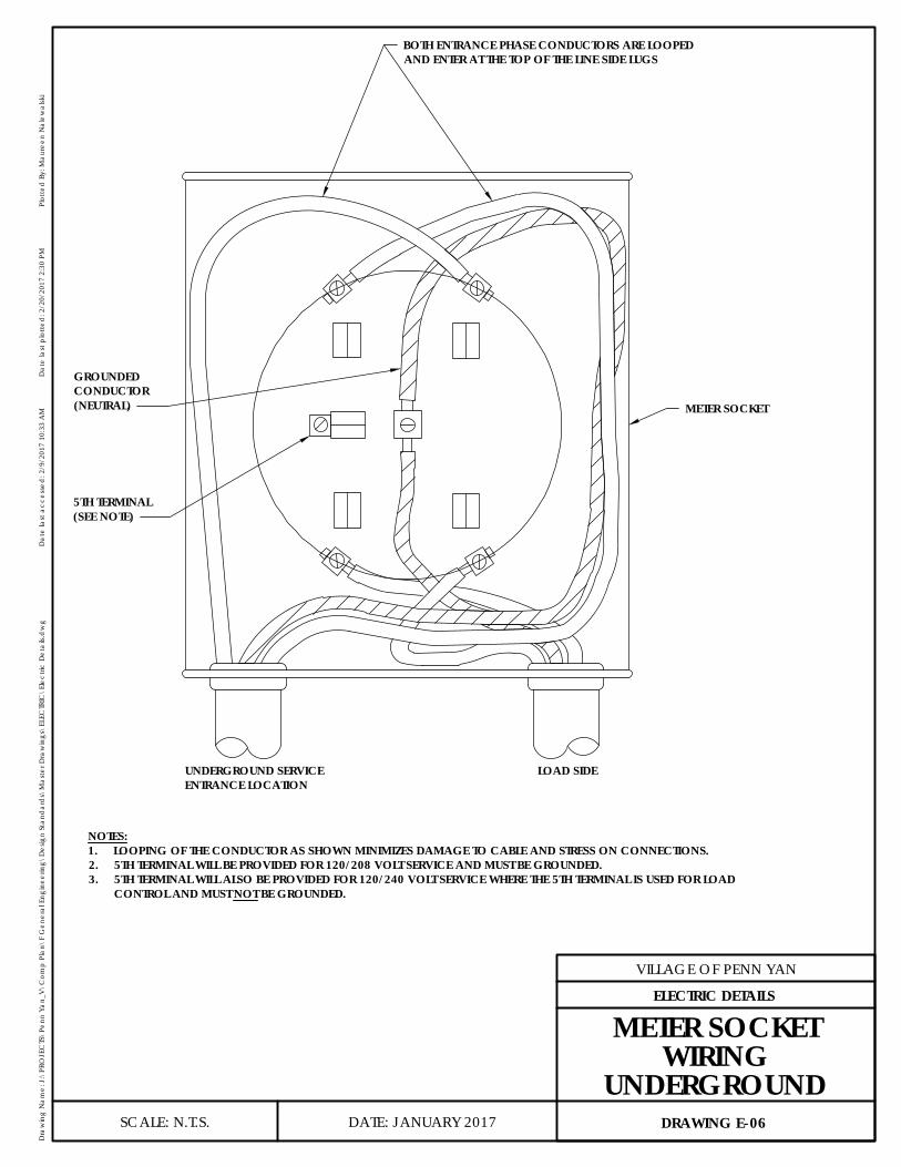
NOTES:1. LOOPING OF THE CONDUCTOR AS SHOWN MINIMIZES DAMAGE TO CABLE AND STRESS ON CONNECTIONS.2. 5TH TERMINAL WILL BE PROVIDED FOR 120/208 VOLT SERVICE AND MUST BE GROUNDED.3. 5TH TERMINAL WILL ALSO BE PROVIDED FOR 120/240 VOLT SERVICE WHERE THE 5TH TERMINAL IS USED FOR LOAD
CONTROL AND MUST NOT BE GROUNDED.
BOTH ENTRANCE PHASE CONDUCTORS ARE LOOPEDAND ENTER AT THE TOP OF THE LINE SIDE LUGS
METER SOCKET
5TH TERMINAL(SEE NOTE)
GROUNDEDCONDUCTOR(NEUTRAL)
UNDERGROUND SERVICEENTRANCE LOCATION
LOAD SIDE
DATE: JANUARY 2017
VILLAGE OF PENN YAN
Dra
win
g N
ame:
J:\
PRO
JEC
TS\P
enn
Yan_
V\C
omp
Plan
\F G
ener
al E
ngin
eerin
g\D
esig
n St
and
ard
s\M
aste
r Dra
win
gs\E
LEC
TRIC
\Ele
ctric
Det
ails.
dw
gD
ate
last
acc
esse
d: 2
/9/2
017
10:3
3 A
MD
ate
last
plo
tted
: 2/2
0/20
17 2
:30
PMPl
otte
d B
y: M
aure
en N
alew
alsk
i
SCALE: N.T.S. DRAWING E-06
ELECTRIC DETAILS
METER SOCKETWIRING
UNDERGROUND
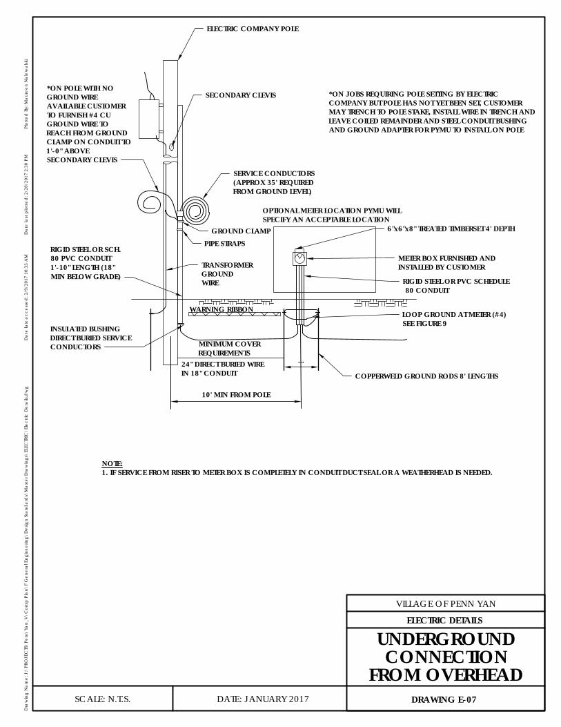
ELECTRIC COMPANY POLE
SECONDARY CLEVIS *ON JOBS REQUIRING POLE SETTING BY ELECTRICCOMPANY BUT POLE HAS NOT YET BEEN SET, CUSTOMERMAY TRENCH TO POLE STAKE, INSTALL WIRE IN TRENCH ANDLEAVE COILED REMAINDER AND STEEL CONDUIT BUSHINGAND GROUND ADAPTER FOR PYMU TO INSTALL ON POLE
GROUND CLAMP
10' MIN FROM POLE
...
COPPERWELD GROUND RODS 8' LENGTHS
RIGID STEEL OR PVC SCHEDULE 80 CONDUIT
*ON POLE WITH NOGROUND WIREAVAILABLE CUSTOMERTO FURNISH #4 CUGROUND WIRE TOREACH FROM GROUNDCLAMP ON CONDUIT TO1'-0" ABOVESECONDARY CLEVIS
SERVICE CONDUCTORS(APPROX 35' REQUIREDFROM GROUND LEVEL)
PIPE STRAPS
TRANSFORMERGROUNDWIRE
OPTIONAL METER LOCATION PYMU WILLSPECIFY AN ACCEPTABLE LOCATION
6"x6"x8" TREATED TIMBERSET 4' DEPTH
LOOP GROUND AT METER (#4)SEE FIGURE 9
METER BOX FURNISHED ANDINSTALLED BY CUSTOMER
NOTE:1. IF SERVICE FROM RISER TO METER BOX IS COMPLETELY IN CONDUIT DUCT SEAL OR A WEATHERHEAD IS NEEDED.
24" DIRECT BURIED WIREIN 18" CONDUIT
MINIMUM COVERREQUIREMENTS
WARNING RIBBON
RIGID STEEL OR SCH.80 PVC CONDUIT1'-10" LENGTH (18"MIN BELOW GRADE)
INSULATED BUSHINGDIRECT BURIED SERVICECONDUCTORS
DATE: JANUARY 2017
VILLAGE OF PENN YAN
Dra
win
g N
ame:
J:\
PRO
JEC
TS\P
enn
Yan_
V\C
omp
Plan
\F G
ener
al E
ngin
eerin
g\D
esig
n St
and
ard
s\M
aste
r Dra
win
gs\E
LEC
TRIC
\Ele
ctric
Det
ails.
dw
gD
ate
last
acc
esse
d: 2
/9/2
017
10:3
3 A
MD
ate
last
plo
tted
: 2/2
0/20
17 2
:30
PMPl
otte
d B
y: M
aure
en N
alew
alsk
i
SCALE: N.T.S. DRAWING E-07
ELECTRIC DETAILS
UNDERGROUNDCONNECTION
FROM OVERHEAD

6" x 6" x 8' TIMBER SET 4 FOOT DEPTH
CABLE ENDS TO BE MOISTURE SEALED
LOOP GROUND ATMETER (#4 CU)SEE FIG. 9
RIGID STELL IMC ORPVC SCHEDULE80 CONDUIT
COPPERWELD GROUND RODS 8' LENGTH
6'
2'
TRANSFORMER VAULTPAD OR HANDHOLELOCATION
GROUND LINE
NOTE:1. THE SERVICE CABLE AND CONDUIT (IF USED) ARE NOT TO BE INSTALLED CLOSER THAN TWO (2) FEET FROM THE
TRANSFORMER OR HANDHOLE LOCATION.
METER BOXFURNISHED ANDINSTALLED BYCUSTOMER
DATE: JANUARY 2017
VILLAGE OF PENN YAN
Dra
win
g N
ame:
J:\
PRO
JEC
TS\P
enn
Yan_
V\C
omp
Plan
\F G
ener
al E
ngin
eerin
g\D
esig
n St
and
ard
s\M
aste
r Dra
win
gs\E
LEC
TRIC
\Ele
ctric
Det
ails.
dw
gD
ate
last
acc
esse
d: 2
/9/2
017
10:3
3 A
MD
ate
last
plo
tted
: 2/2
0/20
17 2
:30
PMPl
otte
d B
y: M
aure
en N
alew
alsk
i
SCALE: N.T.S. DRAWING E-08
ELECTRIC DETAILS
U.G. CONNECTIONFOR RESIDENTIALDEVELOPMENT
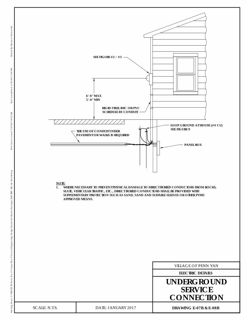
SEE FIGURE #2 / #3
RIGID STEEL IMC OR PVCSCHEDULE 80 CONDUIT
LOOP GROUND AT HOUSE (#4 CU)SEE FIGURE 9THE USE OF CONDUIT UNDER
PAVEMENT OR WALKS IS REQUIRED
PANEL BOX
1.4256
NOTE:1. WHERE NECESSARY TO PREVENT PHYSICAL DAMAGE TO DIRECT BURIED CONDUCTORS FROM ROCKS,
SLATE, VEHICULAR TRAFFIC, ETC., DIRECT BURIED CONDUCTORS SHALL BE PROVIDED WITHSUPPLEMENTARY PROTECTION SUCH AS SAND, SAND AND SUITABLE SLEEVES OR OTHER PYMUAPPROVED MEANS.
6'-0" MAX5'-0" MIN
DATE: JANUARY 2017
VILLAGE OF PENN YAN
Dra
win
g N
ame:
J:\
PRO
JEC
TS\P
enn
Yan_
V\C
omp
Plan
\F G
ener
al E
ngin
eerin
g\D
esig
n St
and
ard
s\M
aste
r Dra
win
gs\E
LEC
TRIC
\Ele
ctric
Det
ails.
dw
gD
ate
last
acc
esse
d: 2
/9/2
017
10:3
3 A
MD
ate
last
plo
tted
: 2/2
0/20
17 2
:30
PMPl
otte
d B
y: M
aure
en N
alew
alsk
i
SCALE: N.T.S. DRAWING E-07B & E-08B
ELECTRIC DETAILS
UNDERGROUNDSERVICE
CONNECTION

1.2339
4.4526
RAIN PROOF HUB
GROUNDING BUSHING(ON METAL CONDUIT)
LOCKNUT
PIPE CLAMP
MOLDING OVERGROUND WIRES
CONDUIT STEEL ORPVC SCHEDULE 80
GROUNDING BUSHING(ON METAL CONDUIT)
METER SOCKET
6'-0" MAX5'-0" MIN
34" PLYWOOD EXTERIOR GRADE
OR EQUIVALENT STRENGTHPRESSURE TREATED LUMBER
GROUNDWIRE #4CU. MIN
18" MIN
3 WIREIN-COMINGSERVICELINE SEENEC 230
4 WIRE TOMOBILEHOME SEENEC 550
NOTES:1. REFER TO FIG. 14 FOR PROPER GROUND CONDUCTORS IN METER SOCKET GROUNDING, IN COMING
CONDUIT SUPPORT TIMBER SAME AS ADJACENT INSTALLATION.
SHOWN WITH TYPICAL SERVICE EQUIPMENT FORMOBILE HOME WITH WIRING 100, 150, OR 200 AMP
METER INSTALLATION ONLYNOT FOR MOBILE HOME USE
DATE: JANUARY 2017
VILLAGE OF PENN YAN
Dra
win
g N
ame:
J:\
PRO
JEC
TS\P
enn
Yan_
V\C
omp
Plan
\F G
ener
al E
ngin
eerin
g\D
esig
n St
and
ard
s\M
aste
r Dra
win
gs\E
LEC
TRIC
\Ele
ctric
Det
ails.
dw
gD
ate
last
acc
esse
d: 2
/9/2
017
10:3
3 A
MD
ate
last
plo
tted
: 2/2
0/20
17 2
:30
PMPl
otte
d B
y: M
aure
en N
alew
alsk
i
SCALE: N.T.S. DRAWING E-09
ELECTRIC DETAILS
TYPICAL METERPEDESTAL
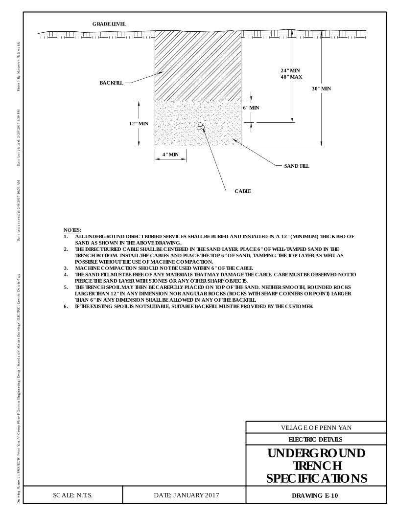
GRADE LEVEL
SAND FILL
BACKFILL
12" MIN
CABLE
4" MIN
6" MIN
30" MIN
1.985524" MIN48" MAX
NOTES:1. ALL UNDERGROUND DIRECT BURIED SERVICES SHALL BE BURIED AND INSTALLED IN A 12" (MINIMUM) THICK BED OF
SAND AS SHOWN IN THE ABOVE DRAWING.2. THE DIRECT BURIED CABLE SHALL BE CENTERED IN THE SAND LAYER. PLACE 6" OF WELL-TAMPED SAND IN THE
TRENCH BOTTOM. INSTALL THE CABLES AND PLACE THE TOP 6" OF SAND, TAMPING THE TOP LAYER AS WELL ASPOSSIBLE WITHOUT THE USE OF MACHINE COMPACTION.
3. MACHINE COMPACTION SHOULD NOT BE USED WITHIN 6" OF THE CABLE.4. THE SAND FILL MUST BE FREE OF ANY MATERIALS THAT MAY DAMAGE THE CABLE. CARE MUST BE OBSERVED NOT TO
PIERCE THE SAND LAYER WITH STONES OR ANY OTHER SHARP OBJECTS.5. THE TRENCH SPOIL MAY THEN BE CAREFULLY PLACED ON TOP OF THE SAND. NEITHER SMOOTH, ROUNDED ROCKS
LARGER THAN 12" IN ANY DIMENSION NOR ANGULAR ROCKS (ROCKS WITH SHARP CORNERS OR POINT) LARGERTHAN 6" IN ANY DIMENSION SHALL BE ALLOWED IN ANY OF THE BACKFILL.
6. IF THE EXISTING SPOIL IS NOT SUITABLE, SUITABLE BACKFILL MUST BE PROVIDED BY THE CUSTOMER.
DATE: JANUARY 2017
VILLAGE OF PENN YAN
Dra
win
g N
ame:
J:\
PRO
JEC
TS\P
enn
Yan_
V\C
omp
Plan
\F G
ener
al E
ngin
eerin
g\D
esig
n St
and
ard
s\M
aste
r Dra
win
gs\E
LEC
TRIC
\Ele
ctric
Det
ails.
dw
gD
ate
last
acc
esse
d: 2
/9/2
017
10:3
3 A
MD
ate
last
plo
tted
: 2/2
0/20
17 2
:30
PMPl
otte
d B
y: M
aure
en N
alew
alsk
i
SCALE: N.T.S. DRAWING E-10
ELECTRIC DETAILS
UNDERGROUNDTRENCH
SPECIFICATIONS
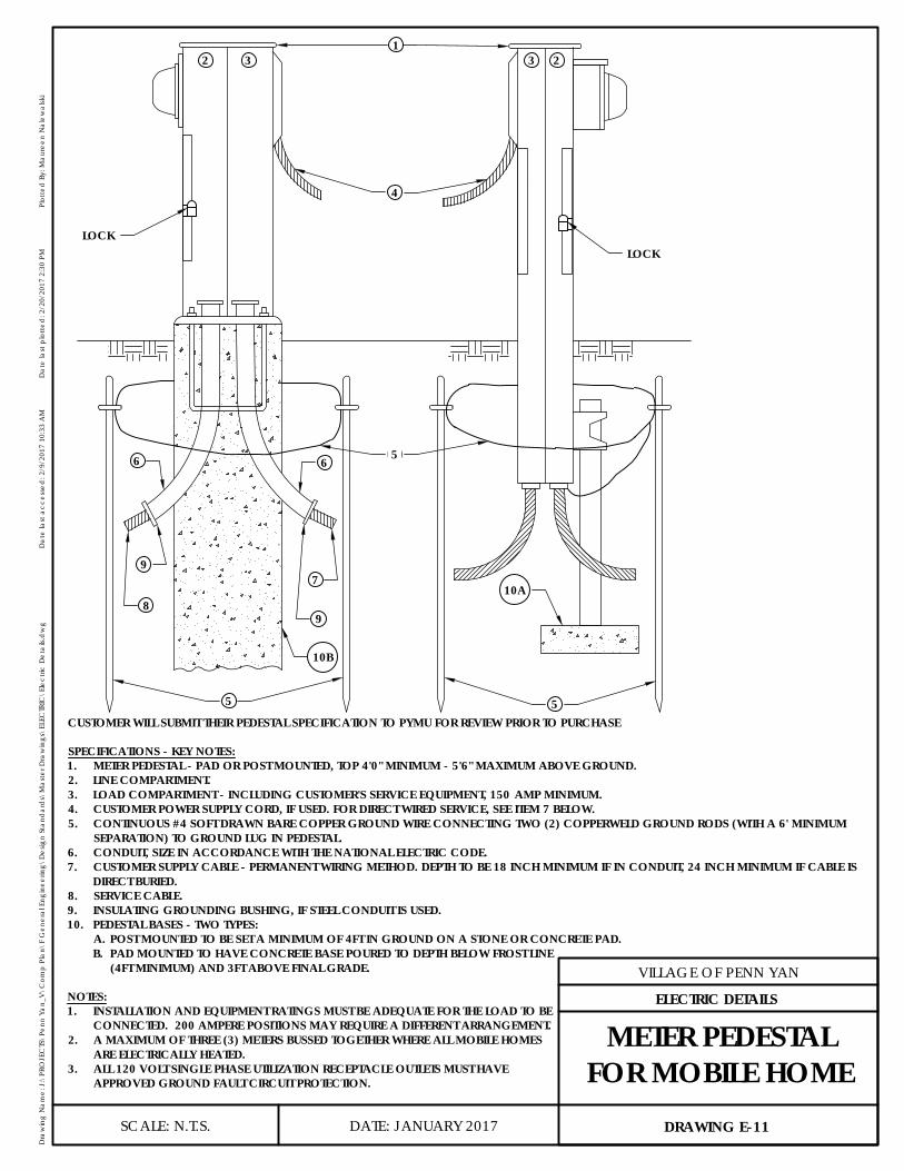
1
4
LOCKLOCK
2 33
5
2
56
9
6
5
9
8
710A
10B
CUSTOMER WILL SUBMIT THEIR PEDESTAL SPECIFICATION TO PYMU FOR REVIEW PRIOR TO PURCHASE
SPECIFICATIONS - KEY NOTES:1. METER PEDESTAL - PAD OR POST MOUNTED, TOP 4'0" MINIMUM - 5'6" MAXIMUM ABOVE GROUND.2. LINE COMPARTMENT.3. LOAD COMPARTMENT - INCLUDING CUSTOMER'S SERVICE EQUIPMENT, 150 AMP MINIMUM.4. CUSTOMER POWER SUPPLY CORD, IF USED. FOR DIRECT WIRED SERVICE, SEE ITEM 7 BELOW.5. CONTINUOUS #4 SOFT DRAWN BARE COPPER GROUND WIRE CONNECTING TWO (2) COPPERWELD GROUND RODS (WITH A 6' MINIMUM
SEPARATION) TO GROUND LUG IN PEDESTAL.6. CONDUIT, SIZE IN ACCORDANCE WITH THE NATIONAL ELECTRIC CODE.7. CUSTOMER SUPPLY CABLE - PERMANENT WIRING METHOD. DEPTH TO BE 18 INCH MINIMUM IF IN CONDUIT, 24 INCH MINIMUM IF CABLE IS
DIRECT BURIED.8. SERVICE CABLE.9. INSULATING GROUNDING BUSHING, IF STEEL CONDUIT IS USED.10. PEDESTAL BASES - TWO TYPES:
A. POST MOUNTED TO BE SET A MINIMUM OF 4FT IN GROUND ON A STONE OR CONCRETE PAD.B. PAD MOUNTED TO HAVE CONCRETE BASE POURED TO DEPTH BELOW FROST LINE
(4FT MINIMUM) AND 3FT ABOVE FINAL GRADE.
NOTES:1. INSTALLATION AND EQUIPMENT RATINGS MUST BE ADEQUATE FOR THE LOAD TO BE
CONNECTED. 200 AMPERE POSITIONS MAY REQUIRE A DIFFERENT ARRANGEMENT.2. A MAXIMUM OF THREE (3) METERS BUSSED TOGETHER WHERE ALL MOBILE HOMES
ARE ELECTRICALLY HEATED.3. ALL 120 VOLT SINGLE PHASE UTILIZATION RECEPTACLE OUTLETS MUST HAVE
APPROVED GROUND FAULT CIRCUIT PROTECTION.
DATE: JANUARY 2017
VILLAGE OF PENN YAN
Dra
win
g N
ame:
J:\
PRO
JEC
TS\P
enn
Yan_
V\C
omp
Plan
\F G
ener
al E
ngin
eerin
g\D
esig
n St
and
ard
s\M
aste
r Dra
win
gs\E
LEC
TRIC
\Ele
ctric
Det
ails.
dw
gD
ate
last
acc
esse
d: 2
/9/2
017
10:3
3 A
MD
ate
last
plo
tted
: 2/2
0/20
17 2
:30
PMPl
otte
d B
y: M
aure
en N
alew
alsk
i
SCALE: N.T.S. DRAWING E-11
ELECTRIC DETAILS
METER PEDESTALFOR MOBILE HOME
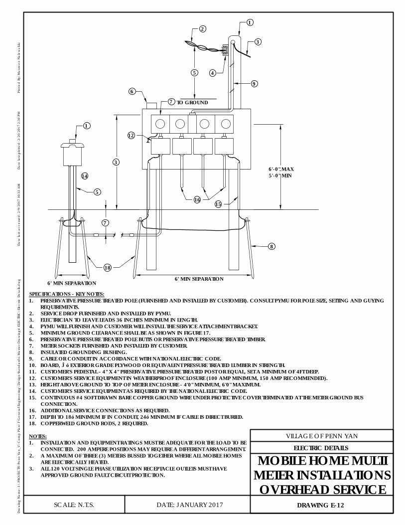
16
5
TO GROUND
21
3
9
7
6
15
5
1
12
14
-3
8
18
-7
4
-6'-0" MAX5'-0" MIN
6' MIN SEPARATION6' MIN SEPARATION
SPECIFICATIONS - KEY NOTES:1. PRESERVATIVE PRESSURE TREATED POLE (FURNISHED AND INSTALLED BY CUSTOMER). CONSULT PYMU FOR POLE SIZE, SETTING AND GUYING
REQUIREMENTS.2. SERVICE DROP FURNISHED AND INSTALLED BY PYMU.3. ELECTRICIAN TO LEAVE LEADS 36 INCHES MINIMUM IN LENGTH.4. PYMU WILL FURNISH AND CUSTOMER WILL INSTALL THE SERVICE ATTACHMENT BRACKET.5. MINIMUM GROUND CLEARANCE SHALL BE AS SHOWN IN FIGURE 17.6. PRESERVATIVE PRESSURE TREATED POLE BUTTS OR PRESERVATIVE PRESSURE TREATED TIMBER.7. METER SOCKETS FURNISHED AND INSTALLED BY CUSTOMER.8. INSULATED GROUNDING BUSHING.9. CABLE OR CONDUIT IN ACCORDANCE WITH NATIONAL ELECTRIC CODE.10. BOARD, ¾” EXTERIOR GRADE PLYWOOD OR EQUIVALENT PRESSURE TREATED LUMBER IN STRENGTH.11. CUSTOMER'S PEDESTAL - 4" X 4" PRESERVATIVE PRESSURE TREATED POST OR EQUAL, SET A MINIMUM OF 4FT DEEP.12. CUSTOMER'S SERVICE EQUIPMENT IN WEATHERPROOF ENCLOSURE (100 AMP MINIMUM, 150 AMP RECOMMENDED).13. HEIGHT ABOVE GROUND TO TOP OF METER ENCLOSURE - 4'0" MINIMUM, 6'0" MAXIMUM.14. CUSTOMER'S SERVICE EQUIPMENT AS REQUIRED BY THE NATIONAL ELECTRIC CODE.15. CONTINUOUS #4 SOFT DRAWN BARE COPPER GROUND WIRE UNDER PROTECTIVE COVER TERMINATED AT THE METER GROUND BUS
CONNECTION.16. ADDITIONAL SERVICE CONNECTIONS AS REQUIRED.17. DEPTH TO 18” MINIMUM IF IN CONDUIT, 24” MINIMUM IF CABLE IS DIRECT BURIED.18. COPPERWELD GROUND RODS, 2 REQUIRED.
NOTES:1. INSTALLATION AND EQUIPMENT RATINGS MUST BE ADEQUATE FOR THE LOAD TO BE
CONNECTED. 200 AMPERE POSITIONS MAY REQUIRE A DIFFERENT ARRANGEMENT.2. A MAXIMUM OF THREE (3) METERS BUSSED TOGETHER WHERE ALL MOBILE HOMES
ARE ELECTRICALLY HEATED.3. ALL 120 VOLT SINGLE PHASE UTILIZATION RECEPTACLE OUTLETS MUST HAVE
APPROVED GROUND FAULT CIRCUIT PROTECTION.
DATE: JANUARY 2017
VILLAGE OF PENN YAN
Dra
win
g N
ame:
J:\
PRO
JEC
TS\P
enn
Yan_
V\C
omp
Plan
\F G
ener
al E
ngin
eerin
g\D
esig
n St
and
ard
s\M
aste
r Dra
win
gs\E
LEC
TRIC
\Ele
ctric
Det
ails.
dw
gD
ate
last
acc
esse
d: 2
/9/2
017
10:3
3 A
MD
ate
last
plo
tted
: 2/2
0/20
17 2
:30
PMPl
otte
d B
y: M
aure
en N
alew
alsk
i
SCALE: N.T.S. DRAWING E-12
ELECTRIC DETAILS
MOBILE HOME MULTIMETER INSTALLATIONSOVERHEAD SERVICE
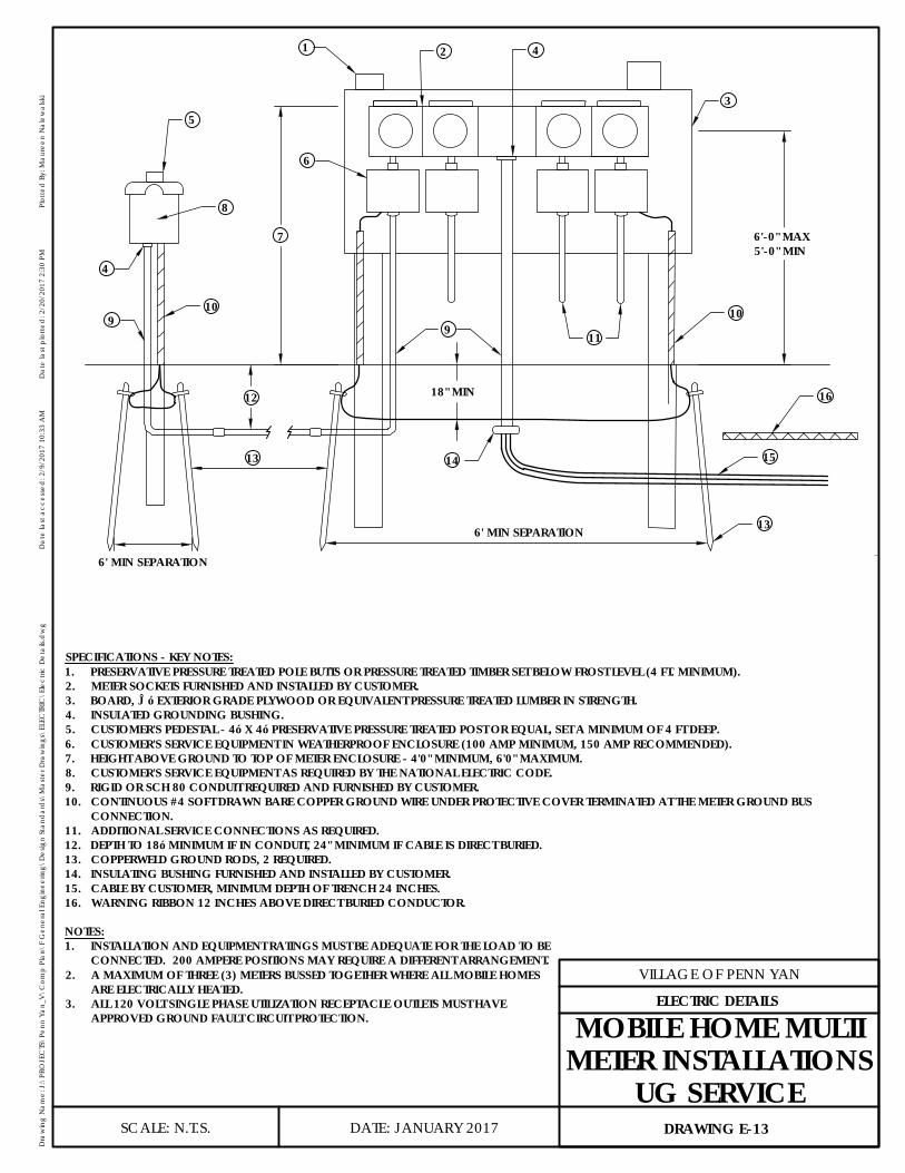
3
421
5
8
4
910
6
119
10
16
15141.2771
0.6089
3.5814
2.1856
13
6'-0" MAX5'-0" MIN
6' MIN SEPARATION
6' MIN SEPARATION
13
12
2.4220 7
0.515418" MIN
SPECIFICATIONS - KEY NOTES:1. PRESERVATIVE PRESSURE TREATED POLE BUTTS OR PRESSURE TREATED TIMBER SET BELOW FROST LEVEL (4 FT. MINIMUM).2. METER SOCKETS FURNISHED AND INSTALLED BY CUSTOMER.3. BOARD, ¾” EXTERIOR GRADE PLYWOOD OR EQUIVALENT PRESSURE TREATED LUMBER IN STRENGTH.4. INSULATED GROUNDING BUSHING.5. CUSTOMER'S PEDESTAL - 4” X 4” PRESERVATIVE PRESSURE TREATED POST OR EQUAL, SET A MINIMUM OF 4 FT DEEP.6. CUSTOMER'S SERVICE EQUIPMENT IN WEATHERPROOF ENCLOSURE (100 AMP MINIMUM, 150 AMP RECOMMENDED).7. HEIGHT ABOVE GROUND TO TOP OF METER ENCLOSURE - 4'0" MINIMUM, 6'0" MAXIMUM.8. CUSTOMER'S SERVICE EQUIPMENT AS REQUIRED BY THE NATIONAL ELECTRIC CODE.9. RIGID OR SCH 80 CONDUIT REQUIRED AND FURNISHED BY CUSTOMER.10. CONTINUOUS #4 SOFT DRAWN BARE COPPER GROUND WIRE UNDER PROTECTIVE COVER TERMINATED AT THE METER GROUND BUS
CONNECTION.11. ADDITIONAL SERVICE CONNECTIONS AS REQUIRED.12. DEPTH TO 18” MINIMUM IF IN CONDUIT, 24" MINIMUM IF CABLE IS DIRECT BURIED.13. COPPERWELD GROUND RODS, 2 REQUIRED.14. INSULATING BUSHING FURNISHED AND INSTALLED BY CUSTOMER.15. CABLE BY CUSTOMER, MINIMUM DEPTH OF TRENCH 24 INCHES.16. WARNING RIBBON 12 INCHES ABOVE DIRECT BURIED CONDUCTOR.
NOTES:1. INSTALLATION AND EQUIPMENT RATINGS MUST BE ADEQUATE FOR THE LOAD TO BE
CONNECTED. 200 AMPERE POSITIONS MAY REQUIRE A DIFFERENT ARRANGEMENT.2. A MAXIMUM OF THREE (3) METERS BUSSED TOGETHER WHERE ALL MOBILE HOMES
ARE ELECTRICALLY HEATED.3. ALL 120 VOLT SINGLE PHASE UTILIZATION RECEPTACLE OUTLETS MUST HAVE
APPROVED GROUND FAULT CIRCUIT PROTECTION.
DATE: JANUARY 2017
VILLAGE OF PENN YAN
Dra
win
g N
ame:
J:\
PRO
JEC
TS\P
enn
Yan_
V\C
omp
Plan
\F G
ener
al E
ngin
eerin
g\D
esig
n St
and
ard
s\M
aste
r Dra
win
gs\E
LEC
TRIC
\Ele
ctric
Det
ails.
dw
gD
ate
last
acc
esse
d: 2
/9/2
017
10:3
3 A
MD
ate
last
plo
tted
: 2/2
0/20
17 2
:30
PMPl
otte
d B
y: M
aure
en N
alew
alsk
i
SCALE: N.T.S. DRAWING E-13
ELECTRIC DETAILS
MOBILE HOME MULTIMETER INSTALLATIONS
UG SERVICE

WHERE METAL WATER PIPE IS IN DIRECT CONTACTWITH EARTH FOR 10 FT OR MORE AND ISELECTRICALLY CONTINUOUS IN ACCORDANCEWITH NEC SECTION 250
METER SOCKET
SERVICE ENTRANCE CONDUCTORS
#4 COPPER GROUND WIRE REQUIRED
1-58"x8" COPPERWELD OR GALVANIZED GROUND ROD
FOR SUPPLEMENTARY GROUND
WATER METER
METAL WATER PIPING
WHERE THE METAL WATER PIPE IS NOT IN DIRECT CONTACT WITH EARTHFOR 10 FT OR MORE AND IS ELECTRICALLY CONTINUOUS INACCORDANCE WITH NEC SECTION 250
METER SOCKET
SERVICE ENTRANCECONDUCTORS
#4 COPPER GROUNDWIRE REQUIRED
WATER METER
6' MIN SEPARATIONBETWEEN RODS
2-58"x8" COPPERWELD
OR GALVANIZED GROUNDROD FOR SUPPLEMENTARY GROUND
METAL WATER PIPING
DATE: JANUARY 2017
VILLAGE OF PENN YAN
Dra
win
g N
ame:
J:\
PRO
JEC
TS\P
enn
Yan_
V\C
omp
Plan
\F G
ener
al E
ngin
eerin
g\D
esig
n St
and
ard
s\M
aste
r Dra
win
gs\E
LEC
TRIC
\Ele
ctric
Det
ails.
dw
gD
ate
last
acc
esse
d: 2
/9/2
017
10:3
3 A
MD
ate
last
plo
tted
: 2/2
0/20
17 2
:30
PMPl
otte
d B
y: M
aure
en N
alew
alsk
i
SCALE: N.T.S. DRAWING E-14
ELECTRIC DETAILS
GROUNDING
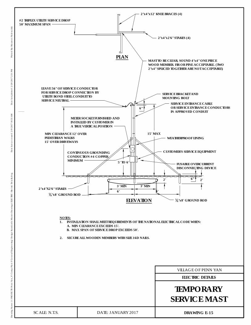
CUSTOMER'S SERVICE EQUIPMENT
WEATHERPROOF LINING
SERVICE ENTRANCE CABLEOR SERVICE ENTRANCE CONDUCTORSIN APPROVED CONDUIT
6"
SERVICE BRACKET ANDMOUNTING BOLT
PLAN
ELEVATION
NOTES:1. INSTALLATION SHALL MEET REQUIREMENTS OF THE NATIONAL ELECTRICAL CODE WHEN:
A. MIN CLEARANCE EXCEEDS 15'.B. MAX SPAN OF SERVICE DROP EXCEEDS 50'.
2. SECURE ALL WOODEN MEMBERS WITH SIZE 16D NAILS.
2"x4"x12' KNEE BRACES (4)
2"x4"x2'6" STAKES (4)
#2 TRIPLEX UTILITY SERVICE DROP50' MAXIMUM SPAN
LEAVE 56" OF SERVICE CONDUCTORFOR SERVICE DROP CONNECTION BY UTILITY BOND STEEL CONDUIT TOSERVICE NEUTRAL
-
MIN CLEARANCE 12' OVERPEDESTRIAN WALKS15' OVER DRIVEWAYS
5' TO 6'
CONTINUOUS GROUNDINGCONDUCTION #4 COPPERMINIMUM
METER SOCKET FURNISHED ANDINSTALLED BY CUSTOMER INA TRUE VERTICAL POSITION
15' MAX
MAST TO BE CLEAR, SOUND 4"x4" ONE PIECEWOOD MEMBER. FIR OR PINE ACCEPTABLE. (TWO2"x4" SPLICED TOGETHER ARE NOT ACCEPTABLE)
FUSABLE OVERCURRENTDISCONNECTING DEVICE
6" 2'
2"x4"X2'6" STAKES5
8"x8' GROUND ROD5
8"x8' GROUND ROD
2'
3' MIN 3' MIN6' 6'
DATE: JANUARY 2017
VILLAGE OF PENN YAN
Dra
win
g N
ame:
J:\
PRO
JEC
TS\P
enn
Yan_
V\C
omp
Plan
\F G
ener
al E
ngin
eerin
g\D
esig
n St
and
ard
s\M
aste
r Dra
win
gs\E
LEC
TRIC
\Ele
ctric
Det
ails.
dw
gD
ate
last
acc
esse
d: 2
/9/2
017
10:3
3 A
MD
ate
last
plo
tted
: 2/2
0/20
17 2
:31
PMPl
otte
d B
y: M
aure
en N
alew
alsk
i
SCALE: N.T.S. DRAWING E-15
ELECTRIC DETAILS
TEMPORARYSERVICE MAST
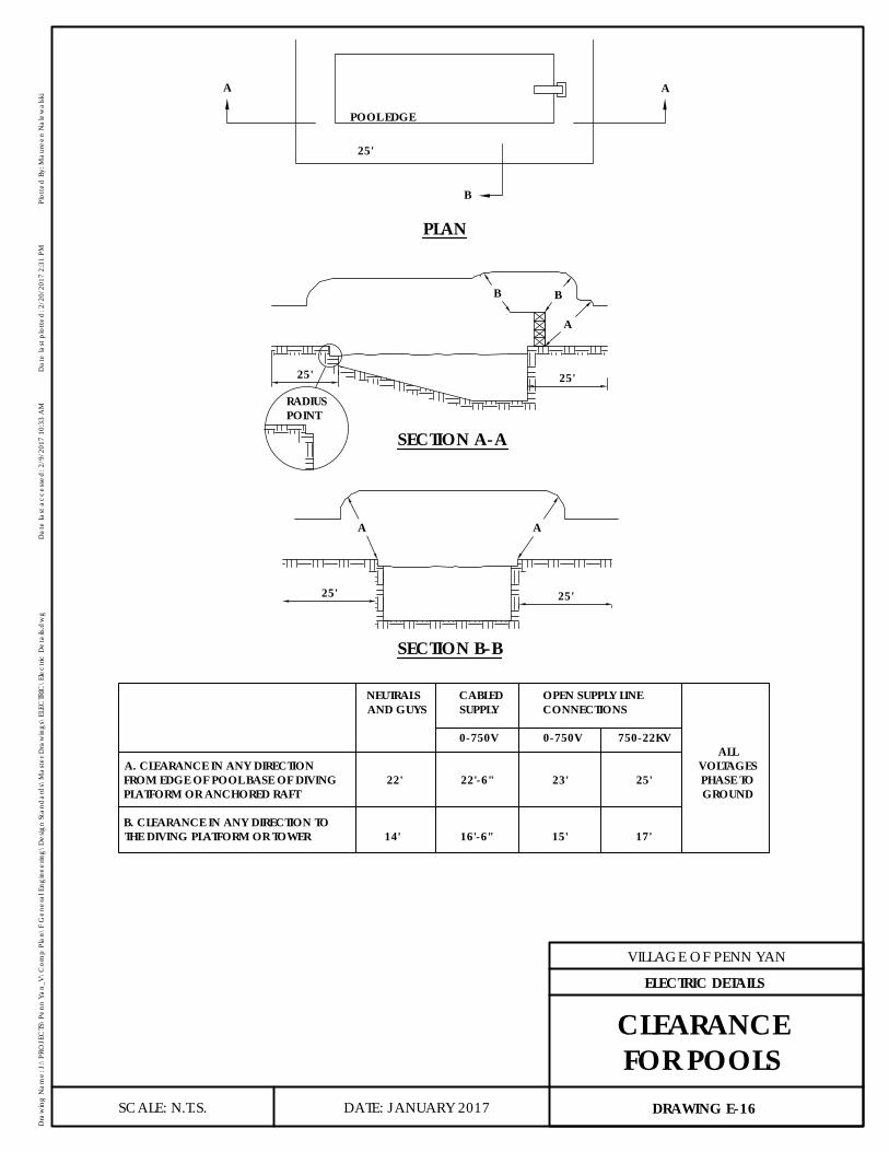
B
AA
POOL EDGE
25'
RADIUSPOINT
SECTION B-B
25'25'
--A A
25'25'
A
BB
SECTION A-A
PLAN
NEUTRALS CABLED OPEN SUPPLY LINEAND GUYS SUPPLY CONNECTIONS
0-750V 0-750V 750-22KVALL
A. CLEARANCE IN ANY DIRECTION VOLTAGESFROM EDGE OF POOL BASE OF DIVING 22' 22'-6" 23' 25' PHASE TOPLATFORM OR ANCHORED RAFT GROUND
B. CLEARANCE IN ANY DIRECTION TOTHE DIVING PLATFORM OR TOWER 14' 16'-6" 15' 17'
DATE: JANUARY 2017
VILLAGE OF PENN YAN
Dra
win
g N
ame:
J:\
PRO
JEC
TS\P
enn
Yan_
V\C
omp
Plan
\F G
ener
al E
ngin
eerin
g\D
esig
n St
and
ard
s\M
aste
r Dra
win
gs\E
LEC
TRIC
\Ele
ctric
Det
ails.
dw
gD
ate
last
acc
esse
d: 2
/9/2
017
10:3
3 A
MD
ate
last
plo
tted
: 2/2
0/20
17 2
:31
PMPl
otte
d B
y: M
aure
en N
alew
alsk
i
SCALE: N.T.S. DRAWING E-16
ELECTRIC DETAILS
CLEARANCEFOR POOLS

18" MIN
0.28043' MIN FROM ROOFTO BOTTOM WIRE
18' MIN OVER INDUSTRIAL AND COMMERCIALDRIVEWAYS AND PUBLIC STREETS
12' MIN OVER SPACES ACCESSIBLE TO PEDESTRIANSINCLUDING SIDEWALKS WITH CONDUCTORS 150 VOLTSTO GROUND OR LESS
12' MIN OVER RESIDENTIALDRIVEWAYS. AUTOMOBILEPARKING LOTS, DRIVE INESTABLISHMENTS, ANDSIMILAR COMMERCIALAREAS SHALL BE 15' MINHEIGHT.
*12' MIN, 25' MAX HEIGHT OF ATTACHMENT TOLOWEST WIRE ABOVE FINAL GRADE
*IN MOST CASES, THIS MIN HEIGHT MUST BEINCREASED TO MAINTAIN OTHER MINCLEARANCE FIGURES SHOWN ON THIS DRAWING
4' MAX
3'MIN
10' MIN OVERFLAT ROOFS
DATE: JANUARY 2017
VILLAGE OF PENN YAN
Dra
win
g N
ame:
J:\
PRO
JEC
TS\P
enn
Yan_
V\C
omp
Plan
\F G
ener
al E
ngin
eerin
g\D
esig
n St
and
ard
s\M
aste
r Dra
win
gs\E
LEC
TRIC
\Ele
ctric
Det
ails.
dw
gD
ate
last
acc
esse
d: 2
/9/2
017
10:3
3 A
MD
ate
last
plo
tted
: 2/2
0/20
17 2
:31
PMPl
otte
d B
y: M
aure
en N
alew
alsk
i
SCALE: N.T.S. DRAWING E-17
ELECTRIC DETAILS
VERTICALCLEARANCE FOR
SERVICE DROP