informational proposal - nebraska106).pdf · informational proposal ... this proposal contains a...
TRANSCRIPT

INFORMATIONAL PROPOSAL(For information only, not to be used for bidding)
NEBRASKA DEPARTMENT OF ROADSLETTING DATE: November 10, 2016
CALL ORDER: 400 CONTRACT ID: 4914CONTROL NO. SEQ. NO.: 41914 000 PROJECT NO.: STP-70-4(106)
TENTATIVE START DATE: 03/27/2017 CONTRACT TIME: 587 Calendar DaysLOCATION: N-70, ORD NORTH
IN COUNTY: VALLEYBIDDER
GROUP 1GROUP 3GROUP 4GROUP 4AGROUP 5GROUP 6GROUP 6AGROUP 7GROUP 7BGROUP 8BGROUP 10
GRADING CONCRETE PAVEMENT CULVERTS CULVERT AT STA 2022+80 SEEDING BRIDGE AT STA 115+29 BRIDGE AT STA 115+29 GUARDRAIL FENCE ELECTRICAL GENERAL ITEMS
THIS PROPOSAL CONTAINS A DBE GOAL OF 4.00 %
SEE SPECIAL PROVISIONS FOR GROUP TIES
THE TOTAL AMOUNT OR WORK WHICH WILL BE ACCEPTED INTHIS LETTING IS LIMITED TO $______________________
THE NUMBER OF GROUP ____________ CONTRACTS WHICH WILL BEACCEPTED IN THIS LETTING IS LIMITED TO ____________.
NOTES
- 1 -

Project No. STP-70-4(106)
- 2 -
NOTICE TO ALL BIDDERS To report bid rigging activities, call: 1-800-424-9071 The U.S. Department of Transportation (DOT) operates the above toll-free “hotline” Monday through Friday, 8:00 a.m. to 5:00 p.m. eastern time. Anyone with knowledge of possible bid rigging, bidder collusion, or other fraudulent activities should use the “hotline” to report such activities. The “hotline” is part of the DOT’s continuing effort to identify and investigate highway construction contract fraud and abuse and is operated under the direction of the DOT Inspector General. All information will be treated confidentially and caller anonymity will be respected.
LETTING QUESTIONS
Prior to the letting, any questions pertaining to the Special Provisions or the Plans for this project should be submitted to NDOR in a written format through the Bid Express (BidX) website at https://www.bidx.com/ne/lettings. Likewise, NDOR will post answers exclusively to the BidX website. All official answers will be identified as “Authorized by NDOR.” Questions will not be answered verbally.

Project No. STP-70-4(106)
- 3 -

Project No. STP-70-4(106)
- 4 -

Project No. STP-70-4(106)
- 5 -

Project No. STP-70-4(106)
- 6 -
Project No. STP-70-4(106)
- 7 -

Project No. STP-70-4(106)
- 8 -

Project No. STP-70-4(106)
- 9 -

Project No. STP-70-4(106)
- 10 -

Project No. STP-70-4(106)
- 11 -

Project No. STP-70-4(106)
- 12 -

Project No. STP-70-4(106)
- 13 -

Project No. STP-70-4(106)
- 14 -

Project No. STP-70-4(106)
- 15 -

Project No. STP-70-4(106)
- 16 -

Project No. STP-70-4(106)
- 17 -

Project No. STP-70-4(106)
- 18 -

Project No. STP-70-4(106)
- 19 -

Project No. STP-70-4(106)
- 20 -
General Decision Number: NE160031 01/08/2016 NE31 Superseded General Decision Number: NE20150031 State: Nebraska Construction Type: Highway Counties: Adams, Blaine, Buffalo, Clay, Custer, Franklin, Garfield, Greeley, Hall, Hamilton, Harlan, Howard, Kearney, Loup, Merrick, Nance, Nuckolls, Phelps, Sherman, Valley, Webster and Wheeler Counties in Nebraska. HIGHWAY CONSTRUCTION PROJECTS Note: Under Executive Order (EO) 13658, an hourly minimum wage of $10.15 for calendar year 2016 applies to all contracts subject to the Davis-Bacon Act for which the solicitation was issued on or after January 1, 2015. If this contract is covered by the EO, the contractor must pay all workers in any classification listed on this wage determination at least $10.15 (or the applicable wage rate listed on this wage determination, if it is higher) for all hours spent performing on the contract in calendar year 2016. The EO minimum wage rate will be adjusted annually. Additional information on contractor requirements and worker protections under the EO is available at www.dol.gov/whd/govcontracts. Modification Number Publication Date 0 01/08/2016 * ENGI0571-005 01/01/2013 Rates Fringes OPERATOR: Trencher..............$ 20.83 9.60 ---------------------------------------------------------------- * SUNE2011-027 08/29/2011 Rates Fringes CARPENTER........................$ 17.16 CEMENT MASON/CONCRETE FINISHER Adams, Blaine, Buffalo, Clay, Franklin, Garfield, Greeley, Hall, Hamilton, Harlan, Howard, Kearney, Loup, Merrick, Nance, Nuckolls, Phelps, Sherman, Valley Webster, Wheele Counties....................$ 14.06 Custer County...............$ 15.38

Project No. STP-70-4(106)
- 21 -
ELECTRICIAN, Includes Installation of Traffic Signals..........................$ 19.00 FENCE ERECTOR....................$ 12.83 HIGHWAY/PARKING LOT STRIPING: Laborer Adams, Blaine, Buffalo, Custer, Clay, Franklin, Garfield, Greeley, Hall, Hamilton, Harlan, Howard, Loup, Merrick, Nance, Nuckolls, Phelps, Sherman, Valley Webster, & Wheele Counties....................$ 11.49 Kearney County..............$ 12.00 IRONWORKER, REINFORCING..........$ 17.93 LABORER: Common or General Adams County................$ 11.52 Blaine, Clay, Franklin, Garfield, Greeley, Howard, Kearney, Loup, Merrick, Nance, Phelps, Sherman, Webster & Wheeler Counties..$ 11.39 Buffalo County..............$ 9.43 Custer County...............$ 11.12 Hall County.................$ 12.79 Hamilton County.............$ 12.77 Harlan County...............$ 12.24 Nuckolls County.............$ 10.64 Valley County...............$ 11.13 LABORER: Landscape & Irrigation.......................$ 8.30 LABORER: Mason Tender - Cement/Concrete..................$ 9.75 LABORER: Traffic Control - Flagger and Cone/Barrel Setter Adams County................$ 8.75 Blaine, Clay, Custer, Franklin, Garfield, Greeley, Loup, Merrick, Nance, Nuckolls, Phelps, Webster & Wheeler Counties..$ 10.16 Buffalo County..............$ 10.97 Hall County.................$ 9.72 Hamilton County.............$ 9.65 Harlan County...............$ 11.96 Howard County...............$ 9.35 Kearney County..............$ 9.68 Sherman County..............$ 9.83 Valley County...............$ 11.15

Project No. STP-70-4(106)
- 22 -
LABORER Asphalt Raker...............$ 11.13 Operating Engineers: (Skid Loader)..........................$ 12.96 OPERATOR: Asphalt Plant.........$ 12.75 OPERATOR: Backhoe Loader Combo............................$ 14.33 OPERATOR: Broom/Sweeper.........$ 10.77 OPERATOR: Bulldozer.............$ 15.69 OPERATOR: Chain Saw.............$ 13.35 OPERATOR: Compactor.............$ 10.05 OPERATOR: Crane Adams, Blaine, Buffalo, Custer, Clay, Franklin, Garfield, Greeley, Hall, Hamilton, Howard, Kearney, Loup, Merrick, Nance, Nuckolls, Phelps, Sherman, Valley Webster, & Wheele Counties....................$ 16.17 Harlan County...............$ 13.60 1.80 OPERATOR: Distributor...........$ 14.37 OPERATOR: Loader Adams, Blaine, Clay, Franklin, Garfield, Greeley, Hamilton, Howard, Kearney, Loup, Marrick, Nance, Nuckolls, Phelps, Sherman, Valley, Webster, Wheeler Counties............$ 14.68 Buffalo County..............$ 15.21 Custer County...............$ 17.58 Hall County.................$ 13.78 Harlan County...............$ 13.02 OPERATOR: Mechanic Adams, Blaine, Buffalo, Custer, Clay, Franklin, Garfield, Greeley, Hamilton, Harland, Howard, Kearney, Loup, Merrick, Nance, Nuckolls, Phelps, Sherman, Valley Webster, & Wheele Counties.............$ 15.42 Hall County.................$ 16.42 OPERATOR: Paver (Asphalt, Aggregate, and Concrete).........$ 12.35

Project No. STP-70-4(106)
- 23 -
OPERATOR: Roller Adams County................$ 12.16 Blaine, Buffalo, Custer, Clay, Franklin, Garfield, Greeley, Hall, Hamilton, Howard, Kearney, Loup, Merrick, Nance, Nuckolls, Phelps, Sherman, Webster, & Wheele Counties...........$ 12.00 Harlan County...............$ 12.86 Valley County...............$ 12.30 OPERATOR: Scraper Adams, Blaine, Buffalo, Custer, Clay, Franklin, Garfield, Greeley, Hall, Hamilton, Howard, Kearney, Loup, Merrick, Nance, Nuckolls, Phelps, Sherman, Valley Webster, & Wheele Counties....................$ 15.79 Harlan County...............$ 15.50 OPERATOR: Screed................$ 12.01 OPERATOR: Tractor Adams, Blaine, Buffalo, Custer, Clay, Franklin, Garfield, Greeley, Hamilton, Harland, Howard, Kearney, Loup, Merrick, Nance, Nuckolls, Phelps, Sherman, Valley Webster, & Wheele Counties.............$ 12.80 Hall County.................$ 13.73 OPERATOR: Grader/Blade Adams County................$ 18.25 Blaine, Buffalo, Custer, Clay, Franklin, Garfield, Greeley, Hamilton, Howard, Kearney, Loup, Merrick, Nance, Nuckolls, Phelps, Sherman, Webster & Wheeler Counties....................$ 15.51 Hall County.................$ 15.85 Harlan County...............$ 14.49 Valley County...............$ 15.48 POWER EQUIPMENT OPERATOR: (BACKHOE, EXCAVATOR, TRACKHOE) Adams, Blaine, Buffalo, Clay, Custer, Franklin, Garfield, Greeley, Hall, Hamilton, Howard, Kearney, Loup, Merrick, Nance, Nuckolls, Phelps, Sherman,

Project No. STP-70-4(106)
- 24 -
Valley, Webster, Wheeler....$ 15.14 Harlan......................$ 14.36 1.71 TRUCK DRIVER (LOWBOY) Adams, Blaine, Buffalo, Custer, Clay, Franklin, Garfield, Greeley, Harland, Howard, Kearney, Loup, Merrick, Nance, Nuckolls, Phelps, Sherman, Valley Webster, & Wheele Counties....................$ 11.99 Hall County.................$ 13.20 Hamilton County.............$ 13.50 TRUCK DRIVER, Includes Dump and Tandem Truck Adams County................$ 12.13 Blaine, Buffalo, Custer, Clay, Franklin, Garfield, Greeley, Harland, Kearney, Loup, Merrick, Nance, Nuckolls, Phelps, Sherman, Valley Webster,& Wheeler Counties....................$ 12.18 Hall & Howard Counties......$ 11.00 Hamilton County.............$ 13.58 TRUCK DRIVER: Oil Distributor Truck................$ 13.25 TRUCK DRIVER: Semi-Trailer Truck............................$ 11.25 TRUCK DRIVER: Water Truck.......$ 11.00 ---------------------------------------------------------------- WELDERS - Receive rate prescribed for craft performing operation to which welding is incidental. ================================================================ Unlisted classifications needed for work not included within the scope of the classifications listed may be added after award only as provided in the labor standards contract clauses (29CFR 5.5 (a) (1) (ii)). ----------------------------------------------------------------

Project No. STP-70-4(106)
- 25 -
The body of each wage determination lists the classification and wage rates that have been found to be prevailing for the cited type(s) of construction in the area covered by the wage determination. The classifications are listed in alphabetical order of "identifiers" that indicate whether the particular rate is a union rate (current union negotiated rate for local), a survey rate (weighted average rate) or a union average rate (weighted union average rate). Union Rate Identifiers A four letter classification abbreviation identifier enclosed in dotted lines beginning with characters other than "SU" or "UAVG" denotes that the union classification and rate were prevailing for that classification in the survey. Example: PLUM0198-005 07/01/2014. PLUM is an abbreviation identifier of the union which prevailed in the survey for this classification, which in this example would be Plumbers. 0198 indicates the local union number or district council number where applicable, i.e., Plumbers Local 0198. The next number, 005 in the example, is an internal number used in processing the wage determination. 07/01/2014 is the effective date of the most current negotiated rate, which in this example is July 1, 2014. Union prevailing wage rates are updated to reflect all rate changes in the collective bargaining agreement (CBA) governing this classification and rate. Survey Rate Identifiers Classifications listed under the "SU" identifier indicate that no one rate prevailed for this classification in the survey and the published rate is derived by computing a weighted average rate based on all the rates reported in the survey for that classification. As this weighted average rate includes all rates reported in the survey, it may include both union and non-union rates. Example: SULA2012-007 5/13/2014. SU indicates the rates are survey rates based on a weighted average calculation of rates and are not majority rates. LA indicates the State of Louisiana. 2012 is the year of survey on which these classifications and rates are based. The next number, 007 in the example, is an internal number used in producing the wage determination. 5/13/2014 indicates the survey completion date for the classifications and rates under that identifier. Survey wage rates are not updated and remain in effect until a new survey is conducted. Union Average Rate Identifiers Classification(s) listed under the UAVG identifier indicate that no single majority rate prevailed for those classifications; however, 100% of the data reported for the classifications was union data. EXAMPLE: UAVG-OH-0010 08/29/2014. UAVG indicates that the rate is a weighted union average rate. OH indicates the state. The next number, 0010 in the example, is an internal number used in producing the wage

Project No. STP-70-4(106)
- 26 -
determination. 08/29/2014 indicates the survey completion date for the classifications and rates under that identifier. A UAVG rate will be updated once a year, usually in January of each year, to reflect a weighted average of the current negotiated/CBA rate of the union locals from which the rate is based. ---------------------------------------------------------------- WAGE DETERMINATION APPEALS PROCESS 1.) Has there been an initial decision in the matter? This can be: * an existing published wage determination * a survey underlying a wage determination * a Wage and Hour Division letter setting forth a position on a wage determination matter * a conformance (additional classification and rate) ruling On survey related matters, initial contact, including requests for summaries of surveys, should be with the Wage and Hour Regional Office for the area in which the survey was conducted because those Regional Offices have responsibility for the Davis-Bacon survey program. If the response from this initial contact is not satisfactory, then the process described in 2.) and 3.) should be followed. With regard to any other matter not yet ripe for the formal process described here, initial contact should be with the Branch of Construction Wage Determinations. Write to: Branch of Construction Wage Determinations Wage and Hour Division U.S. Department of Labor 200 Constitution Avenue, N.W. Washington, DC 20210 2.) If the answer to the question in 1.) is yes, then an interested party (those affected by the action) can request review and reconsideration from the Wage and Hour Administrator (See 29 CFR Part 1.8 and 29 CFR Part 7). Write to: Wage and Hour Administrator U.S. Department of Labor 200 Constitution Avenue, N.W. Washington, DC 20210 The request should be accompanied by a full statement of the interested party's position and by any information (wage payment data, project description, area practice material, etc.) that the requestor considers relevant to the issue.

Project No. STP-70-4(106)
- 27 -
3.) If the decision of the Administrator is not favorable, an interested party may appeal directly to the Administrative Review Board (formerly the Wage Appeals Board). Write to: Administrative Review Board U.S. Department of Labor 200 Constitution Avenue, N.W. Washington, DC 20210 4.) All decisions by the Administrative Review Board are final. ================================================================ END OF GENERAL DECISION

Project No. STP-70-4(106)
- 28 -
SPECIAL PROVISIONS FOR
FEDERAL AID PROJECT NO. STP-70-4(106)
GENERAL CONDITIONS
Bids for the work contemplated in this proposal form will be received at the office of the Nebraska Department of Roads in Room 104 of the Central Office Building at 1500 Highway 2 at Lincoln, Nebraska, on November 10, 2016, until 1:30 P.M. a. Bids submitted by mail should be addressed to the Nebraska Department of Roads,
c/o Contract Lettings Section, P.O. Box 94759, Lincoln, NE 68509-4759. b. Bids submitted electronically over the internet, shall be submitted using www.bidx.com. The 2007 Edition of the Standard Specifications for Highway Construction, including all amendments and additions thereto effective at the date of the contract, are made a part of these Special Provisions, through reference. The Required Contract Provisions, Form FHWA 1273, (Rev. 5-12), and the Notice of Requirement for Affirmative Action to Ensure Equal Employment Opportunity and Standard Federal Equal Employment Opportunity Construction Contract Specifications dated November 3, 1980, are attached to and are a part of this proposal form. The Standard Labor Classifications and Descriptions for Highway Construction dated September 1, 1996, are made a part of these Special Provisions, through reference. The General Wage Decision issued under the Davis-Bacon and Related Acts is attached to and is a part of this proposal form. The attention of bidders is directed to the Required Contract Provisions covering subletting or assigning the contract. GROUPS 1, 3, 4, 4A, 5, 6 OR 6A, 7, 7B, 8B AND 10 ARE TIED TOGETHER AND BIDDING PROPOSAL FORMS FOR THIS WORK WILL BE ISSUED AND A CONTRACT AWARDED TO A CONTRACTOR WHO IS QUALIFIED FOR BRIDGE. GROUPS 6A IS AN ALTERNATE FOR GROUP 6. BIDDERS ARE TO SUBMIT THEIR LOWEST BID ONLY.
DISADVANTAGED BUSINESS ENTERPRISES (A-8-0507)
A. Policy The Contractor agrees to ensure that Disadvantaged Business Enterprises as defined in
49 CFR Part 26 shall have a “level playing field” and equal opportunity to participate in the performance of contracts financed in whole or in part with Federal funds under this

Project No. STP-70-4(106)
- 29 -
contract. Consequently, the Disadvantaged Business requirements of 49 CFR Part 26 are hereby made a part of and incorporated by this reference into this contract.
B. Disadvantaged Business Enterprises Obligation The Contractor agrees to ensure that Disadvantaged Business Enterprises as defined in
49 CFR Part 26 have a “level playing field” and equal opportunity to participate in the performance of contracts and subcontracts financed in whole or in part with Federal funds provided under this agreement. In this regard, the Contractor shall take all necessary and reasonable steps in accordance with 49 CFR Part 26 to ensure that Disadvantaged Business Enterprises have a “level playing field” and equal opportunity to compete for and perform contracts. The Contractor shall not discriminate on the basis of race, color, national origin, or sex in the award and performance of FHWA assisted contracts.
Failure of the Contractor to carry out the requirements set forth above shall constitute breach of contract and, after the notification of the FHWA, may result in termination of the agreement or contract by the State or such remedy as the State deems appropriate.
DISADVANTAGED BUSINESS ENTERPRISES (Prime Contractor Reporting of DBE Payments)
(A-8-1110) This project is funded with Federal Funds and NDOR is required by law to collect DBE payment data from the Contractor. The Prime Contractor shall complete the DBE Total Paid To Date portion on the Monthly Employment Report. This report can be found by using the “Contractor Reports” link at www.nebraskatransportation.org/letting/index.htm. All reports must be completed by the Prime Contractor no later than the 10th day of the following month. No estimates/invoices will be processed until this information is received.
USE OF DISADVANTAGED BUSINESS ENTERPRISES (A-9-0512)
I. INTRODUCTION: The specific requirements of the use of Disadvantaged Business
Enterprises, hereinafter referred to as DBEs, are set forth in these Required Contract Provisions and are imposed pursuant to the Code of Federal Regulations, Title 49, Part 26 and the Nebraska Department of Roads’ Disadvantaged Business Enterprise (DBE) Program, which are hereby made a part of and incorporated by this reference into this proposal. Copies of these documents are available, upon request, from the Nebraska Department of Roads, Disadvantaged Business Enterprise Office, P.O. Box 94759, Lincoln, Nebraska 68509-4759.
A. Definitions:
1. Whenever “NDOR” is used within these special provisions it shall refer to
the Nebraska Department of Roads.

Project No. STP-70-4(106)
- 30 -
2. Whenever “DOT” is used within these special provisions, it shall refer to the United States Department of Transportation.
3. For the purpose of these special provisions, the following definitions will
apply:
a. Disadvantaged Business Enterprise (DBE) means a for profit small business concern, as defined pursuant to Section 3 of the Small Business Act and Small Business Administration regulations implementing it, which is independently owned and controlled by one or more socially and economically disadvantaged individuals.
b. Owned and controlled means a business:
(1) Which is at least 51 percent (51%) owned by one or more
socially and economically disadvantaged individuals or women, or, in the case of a public owned business, such individuals must own at least 51 percent (51%) of each class of voting stock and 51 percent of the aggregate of all stock outstanding.
(2) Whose management and daily business operations are
controlled by one or more of the socially and economically disadvantaged owners.
c. Socially and economically disadvantaged individual means a
person who is a citizen (or lawful permanent resident) of the United States, and who is:
(1) “African American,” which includes persons having origins
in any of the Black racial groups of Africa;
(2) “Hispanic American,” which includes persons of Mexican, Puerto Rican, Cuban, Dominican, Central or South American, or other Spanish or Portuguese culture or origin, regardless of race;
(3) “Native American,” which includes persons who are
American Indians, Eskimos, Aleuts, or Native Hawaiians;
(4) “Asian-Pacific American,” which includes persons whose origins are from Japan, China, Taiwan, Korea, Burma (Myanmar), Vietnam, Laos, Cambodia (Kampuchea), Thailand, Malaysia, Indonesia, the Philippines, Brunei, Samoa, Guam, the U.S. Trust Territories of the Pacific Islands (Republic of Palau), the Commonwealth of the Northern Marianas Islands, Macao, Fiji, Tonga, Kirbati, Juvalu, Nauru, Federated States of Micronesia, or Hong Kong;

Project No. STP-70-4(106)
- 31 -
(5) “Subcontinent Asian American,” which includes persons whose origins are from India, Pakistan, Bangladesh, Bhutan, the Maldives Islands, Nepal or Sri Lanka;
(6) A Woman;
(7) Any additional groups whose members are designated as
socially and economically disadvantaged by the SBA, at such time as the SBA designation becomes effective.
II. DBE CONTRACT GOALS:
A. DBE goals are set by the NDOR for specific contracts. The specific DBE contract goals are stated on the Required DBE Participation Form included in the proposal. The Contractor must meet or exceed the goal or demonstrate good faith efforts to meet the goal. Requirements for submission of DBE good faith effort information are contained in Section IV of these special provisions.
B. A current list of certified DBE firms will be posted on the NDOR website
(www.dor.state.ne.us). Only the DBE firms whose names appear on the list will be considered in meeting the contract goal for this project. The DBE firms will be considered only for the items of work listed under the heading, “Nature of Business.” DBE firms may request to have additional items of work added to their “Nature of Business,” however, no items of work will be added after 5:00 p.m., ten (10) calendar days preceding the letting.
C. Contractors shall, as a minimum, seek DBE subcontractors in the same
geographic area in which they seek subcontractors generally for a given solicitation. If the Contractor cannot meet the DBE goals using DBEs from the normal area, the Contractor will expand its search to a reasonably greater geographic area.
D. Contractors are required to make good faith efforts to replace a DBE
subcontractor that is unable to perform with another DBE. In order to ensure compliance with this requirement, any substitution of DBE subcontractors after execution of the contract must be approved by the NDOR.
E. Contractors are also encouraged to use the services of banks owned and
controlled by minorities and women; however, this will not be counted toward the contract DBE goal.
III. MEETING DBE CONTRACT GOAL CRITERIA: The award of the contract will be made
upon satisfaction of the requirements of these special provisions. The apparent low bidder must either meet or exceed the DBE goals for the contract or satisfy the NDOR that good faith efforts were made to meet the goals.
A. REQUIRED DBE PARTICIPATION INFORMATION: All bidders are required to
submit to the NDOR the "Required DBE Participation Form" with their bid proposal on the form provided in this proposal.

Project No. STP-70-4(106)
- 32 -
B. THE REQUIRED DBE PARTICIPATION FORM SHALL INCLUDE:
1. The names and addresses of the DBE subcontractors that will actually
participate in meeting the contract goal.
2. A complete description (by item number or group, etc.) of the work each named DBE subcontractor will perform.
3. The dollar amount of participation by each named DBE subcontractor.
4. Written and signed documentation from the bidder of commitment to use
a DBE subcontractor whose participation it submits to meet a contract goal.
5. The apparent low bidder must submit written and signed confirmation
from each DBE that it is participating in the contract as provided in the Prime Contractor’s commitment, by 5:00 p.m. on the fifth (5th) calendar day following the letting.
6. If the contract goal is not met, evidence of good faith efforts.
C. The proposal will not be read if the "Required DBE Participation Form" is not
included.
If no DBE participation is intended, the form must indicate that good faith effort documentation will be submitted. A blank form that is signed will be interpreted as meaning no DBE participation is intended and will be read.
Listing options and/or alternates for DBE subcontractors and/or items or groups
of work to be performed is not allowed, and will cause this bid to be declared non-responsive.
Required DBE information shall not be subject to revision after bids are opened.
D. The information submitted on the DBE Participation Form will be verified by the
NDOR. Errors in addition will be treated in accordance with current NDOR specifications and procedures.
E. If the use of non-certified firms or the use of DBE firms not certified for the type of
work indicated results in under achievement of the goal, the bid will be declared non-responsive.
F. If, at any time prior to execution of the contract, previously undetected errors
(such as mathematical errors) result in under-achievement of the goal, the low bidder, along with the other bidders on the project, will be given 5 days from receipt of notification by the NDOR to submit good faith information as outlined in Section IV of these specifications.
The use of firms not certified as DBEs by NDOR, or the use of DBE firms that are
not certified for the type of work indicated by the bidder, are not considered previously undetected errors.

Project No. STP-70-4(106)
- 33 -
G. REQUIRED SUBCONTRACTOR/SUPPLIER QUOTATIONS LIST: All bidders
must provide to the NDOR the identity of all firms who provided quotations on DOT-assisted projects, including both DBEs and non-DBEs.
If no quotations were received, the bidder must indicate this in the space provided.
Each bidder will be required to submit one list per letting to cover all projects bid.
IV. GOOD FAITH DETERMINATION: It is the low bidder's responsibility to meet the DBE
contract goals or to provide sufficient information to enable the NDOR to determine that, prior to bidding, the low bidder actually made good faith efforts to meet such goals.
A. The NDOR will, in the "Apparent Low Bidder" listing (available 24 hours after bid
opening) identify all projects which contain a DBE goal. The listing will indicate the apparent low bidder's status in attaining the goal, i.e., "Contractor Meets DBE Goal," or "Contractor Requires Good Faith Determination."
B. If the low bidder's “Required DBE Participation Form” submitted with the bid
indicates the DBE contract goal will be met, and the NDOR concurs, the contract will proceed toward award and the low bidder need not submit any further DBE information prior to award.
C. Good Faith Information Submittal: If the contract DBE goals have not been met,
the "Apparent Low Bidders" listing will reflect that the apparent low bidder is required to submit good faith effort information. Complete and accurate documented information to support a good faith efforts determination must be submitted by 5:00 p.m. on the fifth (5th) day following the letting.
D. Any other bidder on the contract who requires a good faith effort submittal must
also follow the time frames set forth in "C" above if they wish to be considered for award of the contract. Any bidder who does not meet the submittal deadlines, will not be eligible for award of the contract. (The only exception is a case where the apparent low bidder who met the goal initially is declared ineligible for the award for reasons other than DBE goal attainment.) If this results in a new apparent low bidder who did not initially meet the goal, all other bidders on the contract indicating good faith effort will be notified, and given 5 days after receipt, to submit complete information to support their good faith efforts. Bidders are cautioned by the NDOR to retain documentation of their good faith efforts until an award is made, or all bids are rejected.
E. The NDOR will review all information submitted to determine whether the
apparent low bidder actually made good faith efforts to meet the contract goal. The decision as to whether the good faith efforts are acceptable will be made jointly by a committee comprised of the NDOR Highway Civil Rights Coordinator, the Contracts Letting Manager, and an at-large NDOR staff member appointed by the Director.
A NDOR determination that the low bidder's information failed to show
acceptable good faith efforts shall be cause for declaring the low bid non-responsive. In making a determination, information submitted by other bidders

Project No. STP-70-4(106)
- 34 -
will be considered. If the low bid is declared non-responsive, the above procedure will be applied to the next lowest bid, and other higher bids if necessary, until a bid is found that meets the goal, or establishes that good faith efforts were made to meet it. NDOR reserves the right to reject all bids and readvertise the contract if none of the bids result in a satisfactory level of DBE participation at a reasonable price.
F. Establishing Good Faith Efforts: To demonstrate good faith efforts to meet the
DBE contract goals, documentation shall be maintained and submitted to the NDOR as set forth above. Such documentation may include any or all of the following: This list is not intended to be a mandatory checklist, nor is it intended to be exclusive or exhaustive. Other factors or types of efforts may be relevant in appropriate cases.
1. Soliciting through all reasonable and available means (e.g., attendance at
pre-bid meetings, advertising and/or written notices) the interest of all Certified DBE firms that have the capability to perform the work of the contract. The bidder must solicit this interest within sufficient time to allow the DBE firms to respond to the solicitation. The bidder must determine with certainty if the DBE firms are interested, by taking steps to follow up initial solicitations.
2. Selecting portions of the work to be performed by DBE firms in order to
increase the likelihood that the DBE goals will be achieved. This includes, where appropriate, breaking out contract work items into economically feasible units to facilitate DBE participation, even when the Prime Contractor might otherwise prefer to perform work items with its own workforce.
3. Providing interested DBE firms with adequate information about the
plans, specifications and requirements of the contract in a timely manner to assist them in responding to a solicitation.
4. (1) Negotiating in good faith with interested DBE firms. It is the bidder’s
responsibility to make a portion of the work available to DBE subcontractors and suppliers, and to select those portions of the work or material needs consistent with the available DBE subcontractors and suppliers, so as to facilitate DBE participation. Evidence of such negotiation should include the names, addresses, and telephone numbers of DBE firms that were considered; a description of the information provided regarding the plans and specifications for the work selected for subcontracting; and evidence as to why additional agreements could not be reached for DBE firms to perform the work. (2) A bidder using good business judgment would consider a number of factors in negotiating with subcontractors, including DBE subcontractors, and would take a firm’s price and capabilities as well as contract goals into consideration. However, the fact that there may be some additional costs involved in finding and using DBE firms, is not in itself sufficient reason for a bidder’s failure to meet the contract DBE goal, as long as such costs are reasonable. Also, the ability or desire of a Prime Contractor to perform the work of a contract with its own organization

Project No. STP-70-4(106)
- 35 -
does not relieve the bidder of the responsibility to make good faith efforts. Prime Contractors are not, however, required to accept higher quotes from DBE firms if the price difference is excessive or unreasonable.
5. Not rejecting DBE firms as being unqualified without sound reasons
based on a thorough investigation of their capabilities. The Contractor’s standing within its industry, membership in specific groups, organizations, or associations and political or social affiliations (for example union vs. non-union employee status) are not legitimate causes for the rejection, or non-solicitation of bids in the Contractor’s efforts to meet the project DBE goal.
6. Making efforts to assist interested DBE firms in obtaining bonding, lines of
credit, or insurance as required by the recipient or Contractor.
7. Making efforts to assist interested DBE firms in obtaining necessary equipment, supplies, materials, or related assistance or services.
8. Effectively using the services of available minority/women community
organizations; minority/women contractors’ groups; local, state, and Federal minority/women business assistance offices; and other organizations as allowed on a case-by-case basis to provide assistance in the recruitment and placement of DBEs.
G. If the NDOR's preliminary finding is that the bidder did not demonstrate a
satisfactory effort to meet the contract goal, the bidder may appeal the decision by submitting a written request for reconsideration within three (3) days of the decision. The bidder may then present information either in a written narrative supporting its good faith effort submittal, or may appear in person. Any new information not included in the original submittal will not be used in the final determination. The appeal will be heard by a Hearing Officer appointed by the NDOR Director. The Hearing Officer will be an individual who is knowledgeable about the DBE Program and its good faith efforts provision, but who had no part in the initial decision.
The Hearing Officer will hear the appeal within five (5) days of receipt of the written request, and will issue a written decision within three (3) days after the appeal. The reconsideration process is administratively final and has no further appeal.
V. COMMERCIALLY USEFUL FUNCTION:
A. A Contractor may count toward its DBE goals only expenditures to DBE firms that perform a Commercially Useful Function (CUF) in the work of a contract. A DBE firm is considered to perform a CUF when it is responsible for the execution of a distinct element of the work of a contract, and carrying out its responsibilities by actually performing, managing, and supervising the work involved. The DBE firm must also be responsible for materials and supplies used by the DBE firm on the contract, for negotiating price, determining quality and quantity, ordering the material, installing (where applicable), and paying for the material.

Project No. STP-70-4(106)
- 36 -
B. A DBE Supplier may be considered to perform a CUF if the products or material (other than bulk items: petroleum products, steel, cement, gravel, stone, asphalt) the DBE supplies for a contract are typically kept in stock in a store, warehouse or other establishment maintained by the DBE and regularly sold to the public. The DBE Supplier must be responsible for identifying the specific products or material to be supplied determining price and quantity, and arranging delivery. The DBE Supplier must be paid directly by the Contractor for products or material supplied unless the Contractor and the DBE have provided the NDR a signed agreement as set forth in “DBE Goal Credit, paragraph C” of these Required Contract Provisions.
Guidelines:
1. As a general rule, it is expected that workers on a DBE subcontract shall be regular employees of the DBE subcontractor, and shall be listed on the subcontractor's payroll. A regular employee is a person who would normally be working for the DBE firm on any other subcontract with any other Prime Contractor, and whose immediate past employment has not been with the Prime Contractor on the present project, or with the renter-lessor of equipment being used on the present project.
2. On DBE subcontracts, the DBE must perform or exercise responsibility for at
least 30 percent of the total cost of its contract with its own work force, or the DBE will not be considered to be performing a Commercially Useful Function. (If a DBE subcontracts part of its work to another firm, the value of the subcontracted work may be counted toward DBE goals only if the DBE's subcontractor is itself a DBE. Work that a DBE subcontracts to a non-DBE firm does not count toward DBE goals.)
Operators of leased specialized equipment are included under this provision. In
any case, all employees shall be listed on the DBE firm’s payroll and paid by that firm.
3. In addition, a DBE subcontractor shall be required to designate a project
superintendent/foreman who is a regular employee of the subcontractor, and who shall be active in the day-to-day management of the project.
4. If a DBE subcontractor purchases supplies and/or materials from the Prime
Contractor, which are to be incorporated into the project, the supplies and/or materials will not count toward the established DBE contract goals.
5. TWO PARTY CHECKS: The NDOR does not totally prohibit a DBE firm and a
Prime Contractor from using two-party checks to pay for material and/or supplies under certain circumstances, so long as the Prime Contractor acts solely as a guarantor and the funds do not come from the Prime Contractor. Two-party checks cannot be used unless formal written requests to do so from the DBE firm and the Prime Contractor are delivered to the NDOR DBE Office and written approval is given. If this provision is not strictly followed, the Prime Contractor will not be allowed credit for the cost of the material and/or supplies toward the DBE contract goal commitment. The NDOR will closely monitor the use of two-party checks to avoid abuse of this practice.

Project No. STP-70-4(106)
- 37 -
A DBE does not perform a Commercially Useful Function if its role is limited to that of an extra participant in a transaction, contract, or project through which funds are passed in order to obtain the appearance of DBE participation. In determining whether a DBE is such an extra participant, you must examine similar transactions, particularly those in which DBEs do not participate.
When a Prime Contractor commits to use material and/or supplies provided by a DBE Supplier to meet a DBE contract goal, the DBE Supplier must pay for the material and/or supplies without the use of two-party checks or the cost of the material and/or supplies will not be counted toward the Prime Contractor meeting the contract goal. The only exception to this policy might be if unanticipated circumstances prevent the DBE Supplier from being able to pay for a portion of the material and/or supplies and the use of two-party checks is the only viable alternative. The NDOR DBE Office will make the final determination on allowing the use of two-party checks in all such circumstances.
VI. PROHIBITED PRACTICES:
A. An area of special concern is exclusive arrangements between the Prime Contractor and DBE subcontractors. The DBE subcontractors must be willing to contract with more than one Prime Contractor.
B. Any subcontracting arrangement which artificially inflates DBE participation is not
acceptable. Of utmost concern are the interjection of DBE middlemen or passive conduits and arrangements in which a DBE subcontractor is acting essentially as a broker.
VII. ADMINISTRATION OF THE DBE PROGRAM:
A. The NDOR intends to achieve its annual overall DBE participation goal with a “narrowly tailored” DBE Program that meets the “strict scrutiny” requirements as defined by case law. The NDOR will adhere to all of the rules and regulations of the DOT’s DBE Program Regulations as contained in 49 CFR Part 26.
It is the intention of the NDOR that DBE subcontractors be independent
companies, and function in the same capacity as majority Contractors. It is not the intention of the NDOR to be involved with "in name only" DBE subcontractors who are not providing a Commercially Useful Function to the highway industry. The following will be used in administering the DBE Program.
Situation #1:
Prime Contractor “A” subcontracts to a DBE subcontractor, who performs the work with its own workforce (the employees work on a full-time basis for the DBE firm, or were hired from a union hall, employment service, or other hiring sources by the DBE firm, and are supervised by a full-time employee of the DBE), and uses its own equipment, or equipment rented or leased from an equipment dealer. Prime Contractor “A” is not involved in the DBE firm’s operation, other than coordinating when the work is to be performed, and/or other normal industry practices of contracts between a Prime Contractor and a subcontractor.

Project No. STP-70-4(106)
- 38 -
This is the ideal situation, is totally acceptable, and is within the intent of the DBE Program.
Situation #2:
Prime Contractor “A” subcontracts to a DBE firm, that performs the work with its own workforce, (the employees work on a full-time basis for the DBE firm, or were hired from a union hall, employment service, or other sources by the DBE firm for the project, and are supervised by a full-time employee of the DBE). The DBE firm uses equipment owned by a majority Contractor, (other than Prime Contractor “A”), on a long-term rent or lease arrangement at rates consistent with normal industry standards, and not leased on an “as equipment is needed” basis. This situation would be no different than the DBE firm leasing or renting equipment from a commercial equipment supplier.
This is totally acceptable, and is within the intent of the DBE Program.
Situation #3:
A DBE firm is a subcontractor to Prime Contractor "A." When it is time for the subcontract work to be performed, the work is actually performed using Prime Contractor "A's" equipment, work force, and supervisory personnel. The DBE firm then makes a certified payroll using the names of Prime Contractor "A's" employees. Basically, the subcontract work was performed by Prime Contractor “A.” This is a very close association with the Prime Contractor, and the DBE’s owner is not considered to be in control of the DBE firm, or the project in question.
This situation described is not considered to be a Commercially Useful Function, and may be subject to any of the administrative actions as cited in Section VIII, C. below.
Situation #4:
A DBE firm is a subcontractor to Prime Contractor "A.” When it is time for the subcontract work to be performed, the work is actually done using the workforce, equipment, and supervisory personnel of a majority Contractor, Contractor “B.” The DBE firm makes a certified payroll showing Contractor "B's" employees. This condition is not considered to be within the intent of the DBE Program. In reality, majority Contractor "B" is the one that performed the work. The NDOR does not consider this to be a Commercially Useful Function, as Prime Contractor "A" is actually subcontracting to majority Contractor "B," in an unapproved status, rather than the DBE firm.
This situation described is not considered to be a Commercially Useful Function, and may be subject to any of the administrative actions as cited in Section VIII, C. below.
Situation #5:
Prime Contractor "A" is buying supplies from a DBE Supplier to fulfill the DBE goal. This is only acceptable if the DBE firm is a true supplier. The mere fact that the DBE firm purchases the products or material (other than bulk items: petroleum products, steel, cement, gravel, stone, asphalt) from another supplier or manufacturer, then adds some cost and sells the material to a Prime Contractor, does not constitute the DBE as being a supplier. A DBE Supplier must maintain a place of business with an inventory and be generally recognized as a material supplier.

Project No. STP-70-4(106)
- 39 -
The above situations are very broad and general. While it is known that many different situations may arise, these are basic guidelines used to administer the DBE Program.
The NDOR is more than willing to discuss particular situations with either DBE firms or Prime Contractors prior to a letting in the hope of developing DBE firms.
VIII. INVESTIGATORY POWERS, ADMINISTRATIVE PROCEDURES FOR
ENFORCEMENT AND PENALTIES
A. INVESTIGATORY POWERS:
1. The NDOR specifically reserves the right and power to investigate, monitor and/or review all actions taken, statements made, documents submitted, by any Contractor, subcontractor or DBE firm under the terms of these provisions.
B. ADMINISTRATIVE PROCEDURES FOR ENFORCEMENT:
Whenever the NDOR believes a Contractor, subcontractor or DBE firm may not be operating in compliance with the terms of these provisions, the NDOR will conduct an investigation. If the NDOR finds any person or entity not in compliance with these provisions, the NDOR will notify such person or entity in writing as to the specific instances or matters found to be in non-compliance. At the option of the NDOR, the person or entity shall then be allowed a reasonable time to correct any deficiencies noted, and to come into compliance. In the event that the person or entity cannot, thereafter, come into compliance, or fails or refuses to do so, then the NDOR may impose one or more of the penalties hereafter provided for. It is specifically provided by the NDOR that any person or entity will be found to be out of compliance with these provisions if an investigation reveals any violation or act of such serious or compelling nature that the violation or act indicates a serious lack of business integrity or honesty.
C. PENALTIES:
1. In the event the NDOR finds any Contractor, subcontractor, or DBE firm,
to be out of compliance with these provisions, the NDOR may impose one or more of the following sanctions:
a. Termination of the contract.
b. The DBE firm may be decertified and/or suspended from
participating in the NDOR DBE Program.
c. The Prime Contractor may not be able to count the work performed toward his project DBE goal, and if possible to do so, may need to subcontract other work on the project to DBE subcontractors to achieve the goal.
d. The contract items involved may be considered for a monetary
reduction equal to the amount of work not done by the DBE subcontractor.

Project No. STP-70-4(106)
- 40 -
e. The Prime Contractor may be suspended and/or debarred.
f. If at any time during the life of the contract, it is determined that
the Contractor is out of compliance with these provisions, the NDOR may withhold payment of progress payments.
g. If at the completion of the project, the Contractor is determined to
be out of compliance, the NDOR may sustain damages, the exact extent of which would be difficult or impossible to ascertain and, therefore, in order to liquidate such damages, the monetary difference between the amount stated by the Contractor and the amount actually paid to the DBEs will be deducted from the Contractor's payment as liquidated damages. These damages would be in addition to any liquidated damages assessed in accordance with Subsection 108.08 of the Standard Specifications.
h. Referral to the Attorney General for possible prosecution for fraud.
i. Other action as appropriate, within the discretion of the NDOR.
DISADVANTAGED BUSINESS ENTERPRISE (DBE) GOAL (A-9-0507)
All bidders shall submit written assurance that the minimum goal for Disadvantaged Business Enterprise (DBE) participation will be met. The required DBE Participation Form included in this proposal shall be used. The bidder shall submit the name and address of the DBE(s), a complete description of the participation by the DBE(s), and the dollar value of the participation. If the bidder cannot meet the minimum goal for DBE participation, as specified herein, the bidder shall submit complete documentation of its efforts, following the time limits set forth in IV. A., "Good Faith Information Submittal.” These efforts shall include but not be limited to those stated previously in IV. E., "Establishing Good Faith Efforts." Bidders that fail to meet DBE goals or fail to demonstrate sufficient good faith efforts shall be declared non-responsive and ineligible for award of the contract. Bidders shall assume the responsibility of determining if they are the apparent low bidders by contacting the Nebraska Department of Roads, Contract Lettings Section in Lincoln, Nebraska. Such information is made public 24 hours after the announced time for opening bids. This information is available from the NDOR Internet web site (http://www.dor.state.ne.us/). The contract shall be awarded to the lowest responsive responsible bidder. The standard NDOR procedure concerning subcontractors and suppliers shall apply. The DBE firms identified at the time of bid opening are the firms to whom subcontracts will be issued. The work subcontracted to be done, and the amount to be paid for the work, shall be as identified at the time of bid opening.

Project No. STP-70-4(106)
- 41 -
If the Prime Contractor desires to alter this list after execution of the contract, it must demonstrate to the NDOR that the listed DBE firm(s) is unable to perform, and provide the necessary written justification for approval. Justification must also include written documentation from the affected DBE firm(s) stating their position on the Prime Contractor’s request. There must be a solid basis for any change. Any substitution of the named DBE firms must be approved by the Department of Roads Disadvantaged Business Enterprise Office. Substitution of DBE's will only be allowed when the DBE firm(s) is not able to perform because of default or over-extension on other jobs or other similar justification. A Prime Contractor's ability to negotiate a more advantageous contract with another subcontractor is not considered as a valid basis for change. VERIFICATION OF DBE GOAL COMMITMENTS In order to verify achievement of the DBE commitments on each project, the following forms must be completed and submitted to the NDOR DBE Office. A. DR Form 441, DBE I. This form shall be filled out and submitted by the Prime
Contractor, indicating the DBE firms used, actual work performed, the total amount of money paid to the DBE firms, and the date on which is was paid.
B. DR Form 442, DBE II. This form shall be filled out and submitted by the DBE
subcontractor, indicating the name of the DBE firm, actual work performed, the total amount of money received from the Prime Contractor, and the date on which it was received.
C. The above referenced forms will be sent out by the DBE Office when notification
of the project completion has been received. The forms are also available on NDOR’s website, www.dor.state.ne.us.
SUBLETTING OR ASSIGNING OF CONTRACT (A-9-0807)
Prior to beginning work, a copy of all executed subcontracts, written agreements and/or lease agreements used to meet DBE goals shall be submitted to the Construction Engineer for forwarding to the NDOR DBE office. These copies must contain prices. PROMPT PAYMENT CLAUSE:
The Prime Contractor shall include a “Prompt Payment Clause” as a part of every subcontract (including second tier subcontracts) for work and material. The “Prompt Payment Clause” will require payment to all subcontractors for all labor and material, for work completed, within twenty (20) calendar days of receipt of progress payments from the NDOR for said work. The “Prompt Payment Clause” will also stipulate the return of retainage within thirty (30) calendar days after the subcontractor achieves the specified work as verified by payment from the NDOR.
The failure by the Prime Contractor to carry out the requirements of the “Prompt Payment Clause” and/or timely return of retainage, without just cause, is a material breach of this contract, which may result in the NDOR withholding payment from the Prime Contractor until all

Project No. STP-70-4(106)
- 42 -
delinquent payments have been made (no interest will be paid for the period that payment was withheld), termination of this contract, or other such remedy as the NDOR deems appropriate. NOTE: The Prime Contractor may withhold payment only for just cause, and must notify the NDOR in writing of its intent to withhold payment prior to actually withholding payment. The Prime Contractor shall not withhold, delay or postpone payment without first receiving written approval from the NDOR.
DBE GOAL CREDIT (A-9-1012)
It is the intent of the NDOR to assure eligible DBE firms have a “level playing field” and equal opportunity to participate in federal-aid contracts, and maintain the integrity of the DBE Program. DBE participation is counted toward goals as follows: When a DBE firm participates in a contract, only the value of the work actually performed
by the DBE firm counts toward the goal. A. The entire amount of that portion of a construction contract that is performed by the DBE
firm’s own forces is counted toward the goal. This includes the cost of supplies and materials obtained by the DBE firm for the work of the contract, including supplies purchased or equipment leased by the DBE, but not supplies or equipment the DBE purchases or leases from the Prime Contractor or its affiliate.
Example: A DBE firm furnishing and erecting steel or concrete superstructure members, furnishing and driving piling for bridge structures, furnishing and placing prestressed concrete deck panels, and furnishing and placing panels for retained earth walls will be considered a Commercially Useful Function for attaining contract goals for Disadvantaged Business Enterprise (DBE) participation unless the supplies or materials are purchased from the Prime Contractor or its affiliate. When a DBE subcontractor is responsible for substantially constructing a complete structure the total value of the subcontract may be credited to the DBE goal. Paragraph 8.a. (5) of Subsection 109.07 in the 2007 Edition of the Standard Specifications is void and superseded by the following:
When applicable a DR Form 441, "Identification of DBE Goal Achievement".
B. Manufacturers, Suppliers, and Haulers: DBE Manufacturers may be given 100% credit towards the DBE goal for products they
produce for the contract. DBE Suppliers may be given 60% credit towards the DBE goal for products they furnish
for the contract. DBE Haulers may be given 100% credit towards a DBE goal for the delivery fees
charged.

Project No. STP-70-4(106)
- 43 -
A DBE firm certified as both a supplier and hauler may be given 60% credit for supplying a given product and 100% credit for hauling that same product.
See the DBE Goal Credit Table for a guide to DBE credit. C. Supplier, Supplier/Hauler Required Documentation:
When a DBE Supplier is used to meet a DBE goal on a project, the Prime Contractor must provide a signed subcontract agreement identifying specifically the material and the quantities the DBE firm will be supplying, and the amount the DBE firm will be paid for the material.
When a DBE Supplier/Hauler is used to meet a DBE goal on a project by both supplying and hauling material directly to a project for use by the Prime Contractor, the subcontract agreement must identify the material and the quantities the DBE firm will be supplying and hauling, and the separate amounts to be paid to the DBE firm for the material and the hauling.
If a Prime Contractor has its own plant for manufacturing the concrete or asphalt to be used on the project, the DBE firm may be used to supply and haul material to the plant so long as the material is actually incorporated in the project.
In the situations above, the DBE firm must be paid directly by the Prime Contractor. NOTE: If a Prime Contractor is purchasing concrete or asphalt for the project from a commercial plant, the DBE firm is not allowed to haul material to the commercial plant for DBE goal credit. Subcontractor: A DBE Supplier/Hauler may be used to meet a DBE goal on a project by supplying and/or hauling material to a Subcontractor; however, in order for this to be approved the following requirements must be met: The Subcontractor must be a first-tier subcontractor on the project. The material supplied and hauled by the DBE firm to the Subcontractor shall be incorporated in the project by the Subcontractor. Example: The Prime Contractor is using the Subcontractor to do the paving on the project. The DBE Supplier/Hauler may supply and/or haul aggregate to a plant owned by the Subcontractor provided the plant is set up specifically for the project and the aggregate is only used in the concrete or asphalt for the project. NOTE: If the Subcontractor is doing the paving on the project and is purchasing the concrete or asphalt from a commercial plant, the DBE firm is not allowed to haul material to the commercial plant for DBE goal credit.

Project No. STP-70-4(106)
- 44 -
Documentation Required: When a DBE Supplier/Hauler is to be used to meet a DBE goal on a project by supplying and/or hauling material to a Subcontractor, specific documentation must be provided by the Prime Contractor. 1. The Prime Contractor’s original DBE Commitment information submitted with their bid
must identify the material and quantities the DBE firm will be supplying/hauling to the Subcontractor.
2. DBE Commitment Confirmation must be signed by the Prime Contractor, the
Subcontractor and the DBE firm. 3. A signed agreement (which may include a purchase order) between the Prime
Contractor, the Subcontractor, and the DBE firm identifying specifically how the DBE firm is going to be used to meet the project DBE goal and how payment is to be made to the DBE firm.
NOTE: Load tickets must be maintained and be available for review by the Department to verify the type and amount of material supplied/hauled by the DBE and the dates of delivery.
DESCRIPTIONS (A-9-0108)
Manufacturer - To be certified as a manufacturer, a DBE firm must operate or maintain a factory or establishment that produces, on the premises, the materials, supplies, articles or equipment required under the contract and of the general character described by the specifications.
Supplier - A DBE Supplier, or regular dealer, is a firm that owns, operates, or maintains a store, warehouse, or other establishment in which the materials, supplies, articles, or equipment of the general character described by the specifications, and required under the contract are bought, kept in stock, and regularly sold or leased to the public in the usual course of business. To be a Supplier or regular dealer, the firm must be an established, regular business that engages, as its principal business and under its own name, in the purchase and sale or lease of the products in question.
A DBE firm may be a Supplier or regular dealer in such bulk products as petroleum products, steel, cement, gravel, stone, or asphalt without owning a place of business if the DBE firm both owns and operates distribution equipment for the products. Any supplementing of a DBE Supplier’s or regular dealer’s own distribution equipment shall be by a long-term lease agreement and not on an ad hoc or contract-by-contract basis.
NOTE: It is an unacceptable practice to “drop-ship” items which are not typically stocked by a DBE Supplier. If the DBE Supplier does not inventory or take possession of the items being supplied prior to shipping to a project, the items will not count toward the DBE goal. Items supplied for a project that are not typically stocked by the DBE Supplier will not be counted toward the DBE goal.
Packagers, manufacturers’ representatives, brokers, or other persons who arrange or expedite transactions are not suppliers (regular dealers) within the meaning of this paragraph.

Project No. STP-70-4(106)
- 45 -
Broker - With respect to materials or supplies purchased from a DBE which is neither a manufacturer nor a supplier, DBE goal credit may be given for the entire amount of fees or commissions charged for assistance in the procurement of the materials and supplies, or fees or transportation charges for the delivery of materials or supplies required on a job site, provided the fees are reasonable and not excessive as compared with fees customarily allowed for similar services. However, no credit will be given for any portion of the cost of the materials and supplies themselves toward DBE goals.
Rebar Installer - When a DBE is used to install rebar, the Prime Contractor will receive credit for 100 percent of the cost of the installation. The DBE must be responsible for actually performing, managing, and supervising the work. Rebar Supplier - When a DBE is used to supply rebar, the Prime Contractor will receive credit for 60 percent of the cost of the rebar, provided that the DBE Supplier is performing a Commercially Useful Function (CUF) and is not merely an extra participant in a transaction through which funds are passed in order to obtain the appearance of DBE participation. To perform a CUF, the DBE Supplier must be responsible for negotiating price, determining quality and quantities, ordering, inventorying or taking possession of prior to delivery to a project, and paying for the rebar with the DBE's own funds. The use of two-party checks to pay for the rebar will NOT be allowed. If a DBE Rebar Supplier does not own, operate, or maintain a store, warehouse, or other establishment in which rebar is kept in stock, and regularly sold in the usual course of business, the DBE must both own and operate distribution equipment for rebar. Rebar Supplier/Installer - If a DBE is used to both supply and install rebar, the Prime Contractor will receive 100 percent credit for the cost of the rebar and the cost of the installation, provided that the DBE is performing a CUF and is not merely an extra participant in a transaction through which funds are passed in order to obtain the appearance of DBE participation. To perform a CUF, the DBE must be responsible for negotiating price, determining quality and quantities, ordering, inventorying or taking possession of prior to delivery to a project, and paying for the rebar with the DBE's own funds. The use of two-party checks to pay for the rebar will NOT be allowed. If the DBE Rebar Supplier/Installer does not own, operate, or maintain a store, warehouse, or other establishment in which rebar is kept in stock, and regularly sold in the usual course of business, the DBE must both own and operate distribution equipment for rebar. The DBE SuppIier/Installer must also be responsible for performing, managing, and supervising the installation of the rebar. The above-cited provisions will be closely monitored and Commercial Useful Function Reviews will be conducted by NDOR to ensure compliance. If the provisions are violated in any manner, the Department will impose penalties as prescribed in the contract provision, “USE OF DISADVANTAGED BUSINESS ENTERPRISES,” paragraph VIII. C. 1., a. thru i. Hauler - The DBE firm must be responsible for the management and supervision of the entire trucking operation for which it is responsible on a particular contract. There cannot be a contrived arrangement for the purpose of meeting DBE goals.
The DBE firm must itself own and operate at least one fully licensed, insured, and operational truck used on the contract.

Project No. STP-70-4(106)
- 46 -
The DBE firm receives credit for the total value of the transportation services it provides on the contract using trucks it owns, insures, and operates using drivers it employs.
The DBE firm may lease trucks from another DBE firm, including an owner-operator who is certified as a DBE. The DBE firm that leases trucks from another DBE firm receives credit for the total value of the transportation services the lessee DBE firm provides on the contract.
The DBE firm may also lease trucks from a non-DBE firm, including an owner-operator. The DBE who leases trucks from a non-DBE is entitled to credit for the total value of the transportation services provided by non-DBE lessees not to exceed the value of transportation services provided by DBE-owned trucks on the contract. Additional participation by non-DBE lessees receives credit only for the fee or commission it receives as a result of the lease arrangement.
Example: DBE Firm X uses two of its own trucks on a contract. It leases two trucks from DBE Firm Y and six trucks from non-DBE Firm Z. DBE credit would be awarded for the total value of transportation services provided by DBE Firm X and DBE Firm Y, and may also be awarded for the total value of transportation services provided by four of the six trucks provided by non-DBE Firm Z. In all, full credit would be allowed for the participation of eight trucks. With respect to the other two trucks provided by non-DBE Firm Z, DBE credit could be awarded only for the fees or commissions pertaining to those trucks that Firm X receives as a result of its lease with Firm Z.
For the purposes of the above paragraphs, a lease must indicate that the DBE firm has exclusive use of, and control over the truck. This does not preclude the leased truck from working for others during the term of the lease with the consent of the DBE firm, so long as the lease gives the DBE firm absolute priority for the use of the leased truck. Leased trucks must display the name and identification number of the DBE firm.
If a DBE firm performs in the manner outlined above, it will be performing a Commercially Useful Function.
Pass-throughs and/or brokering will not be tolerated. A pass-through/brokering situation is one in which a DBE firm contracts to haul materials for a project, then hires another hauler to actually perform on the contract.
CERTIFICATION (A-9-0307)
Certain DBE’s may be certified in multiple classifications as manufacturers, suppliers, and haulers. The certification will be limited by the products being manufactured, supplied, or hauled.
For example, a manufacturer of certain steel products or aggregates, may also be a supplier of products they store or deliver, but do not manufacture.
A supplier of bulk products, such as aggregates or fuel, may also be certified as a hauler.

Project No. STP-70-4(106)
- 47 -
DBE GOAL CREDIT TABLE
DBE Manufacturer
&
DBE Hauler
100% Credit for Materials
&
100% Credit for Hauling
DBE Manufacturer
&
Non-DBE Hauler
100% Credit for Materials
&
No Credit for Hauling
Non-DBE Manufacturer
&
DBE Hauler
No Credit for Materials
&
100% Credit for Hauling
DBE Supplier
&
DBE Hauler
60% Credit for Materials
&
100% Credit for Hauling
DBE Supplier
&
Non-DBE Hauler
60% Credit for Materials
&
No Credit for Hauling
Non-DBE Supplier
&
DBE Hauler
No Credit for Materials
&
100% Credit for Hauling

Project No. STP-70-4(106)
- 48 -
TRAINING SPECIAL PROVISIONS This On-the-Job Training (OJT) Program was created by the Federal Highway Administration (FHWA) and the Nebraska Department of Roads (NDOR) to fulfill the Training Special Provisions requirements of federal-aid construction contracts (23 CFR 230, Appendix B to Subpart A). The purpose of the provision is to address the under-representation of minority and female workers in the construction trades through the assignment of OJT training goals. Therefore, the training and upgrading of minorities and women toward journeyman status is a primary objective of this Training Special Provision. Accordingly, the Contractor shall make every effort to enroll minority and women trainees (e.g., by conducting systematic and direct recruitment through public and private sources likely to yield minority and women trainees) to the extent that such persons are available within a reasonable area of recruitment. All Contractors will be responsible for demonstrating the steps that they have taken to recruit minority and women trainees prior to a determination as to whether the Contractor is in compliance with this Training Special Provision. This training commitment is not intended, and shall not be used, to discriminate against any applicant for training, whether a member of a minority group or not. The Contractor shall provide on-the-job training aimed at developing full journey-level status in the type of trade or job classification involved. The number of training hours under this Training Special Provision will be assigned to each Contractor as set forth below. 1. Under the NDOR Contractor-Specific On-the-Job Training (OJT) Program, OJT hours
will be assigned to Contractors and will not be contract or project specific, except as noted in paragraph “a.” below.
a. Contractors who have not received an OJT assignment and are awarded a
federally funded project let by NDOR will be required to fulfill the number of OJT hours as identified in each contract. The number of training hours to be provided under this contract shall be: 2,000 hours.
A Contractor who has received an OJT assignment will be allowed to provide
training on any NDOR-let project on which the Contractor is working as either a Prime Contractor or a subcontractor. A Contractor will have the flexibility to transfer trainees from one project to another after providing notification of the transfer to NDOR.
b. If this project does not have a contract-specific training requirement, or if the
number of training hours is set at zero (0), NDOR will add a training pay item with a nominal 100-hour quantity, that may overrun or underrun, which will be utilized only if the Contractor elects to provide training on this contract.
2. In January each year, NDOR will allocate OJT assignments to Contractors based on the
total average dollar amount of all work performed by a Contractor on NDOR-let projects during the previous three (3) calendar years. The total dollar amount will consist of:
a. The total dollar amount of the Contractor’s prime contracts let by NDOR (both
federal and state funded) minus the total dollar amount of the work subcontracted out to others, and

Project No. STP-70-4(106)
- 49 -
b. The total dollar amount of the subcontract work the Contractor performed for others on NDOR-let projects.
The Contractor’s average dollar amount for the previous three calendar years will be
calculated, and training hours will then be assigned as follows: Three Year Average Training Assignments Under $2,500,000 0 hours $2,500,000 to 5,000,000 1,000 hours Over $5,000,000 to 7,500,000 1,500 hours Over $7,500,000 to 10,000,000 2,000 hours Over $10,000,000 to 15,000,000 3,000 hours Over $15,000,000 to 20,000,000 4,000 hours Over $20,000,000 to 25,000,000 5,000 hours Over $25,000,000 to 30,000,000 6,000 hours Over $30,000,000 to 40,000,000 8,000 hours Over $40,000,000 to 50,000,000 10,000 hours Over $50,000,000 to 60,000,000 12,000 hours Over $60,000,000 15,000 hours
Example: Contractor A, who averaged $28.66 million, would be assigned 6,000 hours of OJT. Contractor B, who averaged $10.33 million, would be assigned 3,000 hours of OJT. Contractor C, who averaged $2.26 million, would not be assigned any OJT hours.
2011 2012 2013 3 Year
Average 2014 OJT Assignment
Contractor A 24.3 33.4 28.3 28.66 6,000 hours Contractor B 9.3 11.9 9.8 10.33 3,000 hours Contractor C 2.3 1.4 3.1 2.26 0 hours
3. The OJT hours assigned to a Contractor in January are to be completed during that
calendar year (e.g., OJT hours assigned in January of 2014 are to be completed during the period of January 1, 2014 thru December 31, 2014).
a. If a Contractor exceeds the number of OJT hours assigned for a calendar year,
the Contractor may request to bank up to 30 percent of the excess hours. Banked hours may then be credited toward the Contractor’s OJT assignment for the next calendar year.
4. A Contractor who has not received an annual OJT assignment and is required to provide
OJT on a contract-specific basis cannot receive credit for any OJT hours provided by any other Contractor working on the project who has received a Contractor-specific OJT assignment.
5. Completion of the annual OJT assignment is the Contractor’s responsibility. The
Contractor is not allowed to assign any of the OJT hours to any other Contractor. The Contractor must make a Good Faith Effort to enroll an adequate number of trainees and provide the trainees a sufficient number of hours training to achieve the Contractor’s annual OJT assignment.

Project No. STP-70-4(106)
- 50 -
6. While trainees may be assigned to NDOR-let federally or state funded projects, the Contractor should attempt to schedule and assign trainees so that at least 50 percent of a trainee’s hours are earned on federally funded projects - unless otherwise approved in advance by NDOR.
7. The Contractor must use an OJT program approved by NDOR and/or the FHWA. An
OJT program shall be approved if it is reasonably calculated to meet the equal employment opportunity obligations of the Contractor and qualify the average trainee for journey-level status in the job classification concerned by the end of the training period. An approved OJT program must specify the number of hours required for a trainee to achieve journey-level status in each job classification. Furthermore, apprenticeship programs registered with the U.S. Department of Labor, Bureau of Apprenticeship and Training, or with a State apprenticeship agency recognized by the Bureau and training programs approved but not necessarily sponsored by the U.S. Department of Labor, Manpower Administration, Bureau of Apprenticeship and Training, shall also be considered acceptable provided they are being administered in a manner consistent with the equal employment obligations of federal-aid highway construction contracts.
8. The Contractor shall furnish each trainee a copy of the OJT Program he/she will follow in
providing the training. The Contractor shall also provide each trainee with a certification showing the type and length of training satisfactorily completed.
9. The Contractor’s Equal Employment Opportunity (EEO) Officer shall be responsible for
administering the Contractor’s OJT and monitoring the trainees’ progress. The EEO Officer shall serve as the point of contact for NDOR regarding OJT information, documentation, and conflict resolution. If necessary, the EEO Officer may designate another individual to assist with the OJT monitoring responsibilities. NDOR must be provided the name and contact information for any such designee.
10. At least seven (7) days prior to commencing training, the Contractor must submit a
“Request for Trainee Approval” form to NDOR for each individual to be enrolled as a trainee and a tentative list of the projects to which the trainee will be assigned. Requests for Trainee Approval may be submitted by mail, fax, or email.
11. If the Contractor submits a “Request for Trainee Approval” form to NDOR for an
individual who is not a minority or female, or cannot replace departing trainees with minorities or females, the Contractor must also produce sufficient Good Faith Efforts documentation of the type set forth below. NDOR may reject non-minority male trainees for entry into the program if it determines that a Contractor failed to make sufficient Good Faith Efforts to hire minorities or female trainees and/or the Contractor failed to document or submit evidence of its Good Faith Efforts to do so.
12. Any training hours provided to a trainee prior to the Contractor receiving approval from
NDOR will not be credited toward the Contractor’s annual OJT assignment. 13. When an individual is first enrolled as a trainee, the individual will be approved for the
number of hours of OJT required to achieve journey-level status in the classification for which the individual is to receive training. (A Contractor will not be penalized if a trainee does not achieve the full number of hours for which the trainee is approved.)

Project No. STP-70-4(106)
- 51 -
14. If the Contractor is unable to provide a trainee the full number of training hours required to achieve journey-level status on one project, the trainee should be transferred to other NDOR-let projects on which the Contractor is working.
15. At least one (1) day before all such transfers of trainees are made, the Contractor must
provide NDOR in writing the name of the trainee and current project, the project to which the trainee will be transferred, and when the transfer is to take place. Notifications of trainee transfers may be submitted by mail, fax, or email.
16. Any training hours provided to a transferred trainee prior to the Contractor having
notified NDOR of the transfer will not be credited toward the Contractor’s annual OJT assignment.
17. No individual may be employed as a trainee in any classification in which they have
successfully completed training leading to journey-level status or in which they have been employed at journey-level. No individual may be employed as a trainee in any classification with a lower skill level than any classification in which they have successfully completed training leading to journey-level status or in which they have been employed at journey-level (e.g., an individual who has achieved journey-level status as an equipment operator may not be trained as a laborer). The Contractor should satisfy this requirement by including appropriate questions in the employee application or by other suitable means. Regardless of the method used, the Contractor's records should document the findings in each case.
An individual may be trained in multiple classifications that require relatively equal skill
levels but different skill sets (e.g., an individual who has received training as a milling machine operator may also receive training as a roller operator, or a scraper operator, etc.). Preferably, an individual should have achieved journey-level status in a classification before beginning training in another classification.
The Contractor must request and receive approval from NDOR for an individual to
receive training in a classification other than the classification for which the individual was originally approved. Any training hours provided prior to receiving approval from NDOR will not be credited toward the Contractor’s annual OJT assignment.
18. Training shall be provided in construction crafts rather than clerk-typist or secretarial-
type positions. Training is permissible in positions that are not assigned to a specific project such as office engineers, estimators, timekeepers, shop mechanics, etc., if the selected OJT program includes these classifications. Training in such positions will not be eligible for reimbursement, but will be eligible to be credited toward the Contractor’s annual OJT assignment.
19. Some off-site training is permissible as long as the training is an integral part of an
approved OJT program and does not comprise a significant part of the overall training (e.g., 16 hours training per trainee per year in areas such as jobsite safety or accident response would be permissible). A copy of a training certificate, agenda, or curriculum must be provided to verify off-site training.
20. The Contractor will be reimbursed $2.00 per each hour of training provided in
accordance with an approved OJT program and the NDOR Training Special Provisions.

Project No. STP-70-4(106)
- 52 -
21. Contractors shall be allowed to transfer trainees or utilize trainees on other NDOR-let projects which do not contain the Training Special Provisions. NDOR will utilize a Change Order / Supplemental Agreement to incorporate the Training Special Provisions and the appropriate pay item into the contracts of such projects.
22. On all federally funded NDOR-let projects, trainees must be paid at least 60 percent of
the appropriate minimum journey-level rate specified in the contract for the first half of the training period, 75 percent for the third quarter, and 90 percent for the last quarter of the training period - or the appropriate rates approved by the U.S. Department of Labor or the U.S. Department of Transportation in connection with the program in which the trainee is enrolled.
23. In order to document and evaluate a trainee’s progress toward journey-level status, the
Contractor must provide NDOR at the end of each month a “Special Training Provision Monthly On-The-Job Training Report” listing each trainee, the number of hours trained during the month, and the total number of hours trained as of the date of the report. NOTE: The monthly reporting requirements may change if/when on-line reporting is implemented by NDOR.
24. If a trainee’s employment is terminated for any reason prior to completion of the number
of OJT hours for which the individual was approved, the Contractor must make Good Faith Efforts to replace the trainee with another minority or female.
25. Contractors must submit an annual summary report to NDOR by January 15th each year
giving an account of all trainee hours provided during the previous year. The report shall show a breakdown of training provided on each project and/or contract.
26. Contractors will have fulfilled their OJT responsibilities if they have provided acceptable
training for the number of hours assigned, or have demonstrated that they made a Good Faith Effort to provide the number of OJT hours assigned. Where a Contractor cannot meet his or her annual training hour goal with females and minorities, the Contractor remains responsible for demonstrating the Good Faith Efforts taken in pursuance of the goal. Examples of what actions constitute Good Faith Efforts are set forth below. NDOR will make compliance determinations regarding the Training Special Provisions based upon either attainment of the annual goal or Good Faith Efforts to meet it.
27. Good Faith Efforts are those designed to achieve equal opportunity through positive,
aggressive, and continuous results-oriented measures (23 CFR § 230.409(g)(4)). Good Faith Efforts should be taken as trainee hiring opportunities arise and when minorities and women are under-represented in the Contractor’s workforce. NDOR will consider all Contractors’ documentation of Good Faith Efforts on a case-by-case basis and take into account the following:
a. Availability of minorities, females, and disadvantaged persons for training; b. The potential for effective training; c. Duration of the contract; d. Dollar value of the contract;

Project No. STP-70-4(106)
- 53 -
e. Total normal work force that the average Contractor could be expected to use; f. Geographic location; g. Type of work; h. The need for journey level individuals in the area. Good Faith Efforts may include, but are not limited to, documentation of efforts to:
Contact minority and female employees to gain referrals on other minority and female applicants;
Refer specific minorities and females to training programs and specifically
request these trainees by name in the future;
Upgrade minority and female unskilled workers into the skilled classifications when possible;
Accept applications at the project site or at the Contractor’s home office;
Review and follow up on previously received applications from minorities and
females when hiring opportunities arise;
Maintain monthly evaluations that monitor efforts made to achieve diversity in the Contractor’s workforce in general (i.e., significant numbers of minorities and females employed on a company-wide basis);
Provide incentives for project management personnel or superintendents when
hiring goals are met on a project (i.e., similar to performance bonuses paid when a job is completed in a timely manner and under budget).
28. Liquidated damages will be assessed the Contractor for failure to demonstrate a Good
Faith Effort to achieve their full OJT assignment or for failure to demonstrate a Good Faith Effort to achieve their full OJT assignment with minority and women trainees.
Liquidated damages will be assessed at the rate of $4.00 per hour for the number of OJT hours not achieved or, even if achieved, the number of OJT hours in which the Contractor fails to demonstrate Good Faith Efforts to hire minorities and women. (e.g., if the Contractor was assigned 3,000 hours but only achieved 2,000 hours and did not demonstrate a Good Faith Effort, the liquidated damages would be assessed at 1,000 hours x $4.00 = $4,000.00.)
29. NDOR will invoice a Contractor for liquidated damages assessed as a result of the
Contractor’s failure to demonstrate a Good Faith Effort to achieve the number of OJT hours assigned.
The Contractor’s failure to promptly pay any invoice for liquidated damages may result in
the Contractor being disqualified to bid work with NDOR for a time period determined by the Director/State Engineer.

Project No. STP-70-4(106)
- 54 -
30. At the end of the calendar year, if the dollar amount of work the Contractor performed on NDOR-let projects is substantially below the three-year average upon which the Contractor’s OJT assignment was based, the Contractor’s OJT goal for that year may be adjusted according to the table in Paragraph 2. above.
31. The established per hour unit price for the item “Training” shall be full compensation for
all costs incurred, which includes but is not limited to providing the necessary supervision, labor, equipment, tools and material. Any additional costs due to payment of wages in excess of the minimum rates specified and for the payment of any fringe benefits shall not be paid for directly, but shall be considered subsidiary to the items for which direct payment is made.
AMENDMENT TO CONSTRUCTION TRAINING REPORT REQUIREMENTS The last sentence under Paragraph C., on Page 5 of the Standard Federal Equal Employment Opportunity Construction Contract Specifications, dated November 3, 1980, is void. FHWA Form 1409 “Federal-aid Highway Construction Contractor’s Semi-Annual Training Report” is not required.
CERTIFICATION FOR FEDERAL-AID CONTRACTS (A-11-0307)
The bidder certifies, by signing and submitting this bid, to the best of his or her knowledge and belief, that: (1) No Federal appropriated funds have been paid or will be paid, by or on behalf of the
undersigned, to any person for influencing or attempting to influence an officer or employee of any Federal agency, a Member of Congress, an officer or employee of Congress, or an employee of a Member of Congress in connection with the awarding of any Federal contract, the making of any Federal grant, the making of any Federal loan, the entering into of any cooperative agreement, and the extension, continuation, renewal, amendment, or modification of any Federal contract, grant, loan, or cooperative agreement.
(2) If any funds other than Federal appropriated funds have been paid or will be paid to any
person for influencing or attempting to influence an officer or employee of any Federal agency, a Member of Congress, an officer or employee of Congress, or an employee of a Member of Congress in connection with this Federal contract, grant, loan, or cooperative agreement, the undersigned shall complete and submit Standard Form-LLL, "Disclosure Form to Report Lobbying," in accordance with its instructions.
This certification is a material representation of fact upon which reliance was placed when this transaction was made or entered into. Submission of this certification is a prerequisite for making or entering into this transaction imposed by Section 1352, Title 31, U.S. Code. Any person who fails to file the required certification shall be subject to a civil penalty of not less than $10,000 and not more than $100,000 for each such failure.

Project No. STP-70-4(106)
- 55 -
The bidder also agrees by submitting his or her bid that he or she shall require that the language of this certification be included in all lower tier subcontracts, which exceed $100,000 and that all such subrecipients shall certify and disclose accordingly.
STATUS OF UTILITIES The following information is current as of August 5, 2016. Aerial and/or underground utility facilities may exist within this project. The Contractor should request a utility status update at the preconstruction conference, and/or prior to starting work. Any utility adjustments or interruption of service for the convenience of the Contractor shall be the sole responsibility of the Contractor. To arrange for utilities to locate and flag their underground facilities, contact Diggers Hotline of Nebraska at 1-800-331-5666, or dial 811. The following utilities have facilities within the project area, and have been provided project plans:
Charter Communications: Charter Communications has buried and aerial communication facilities in conflict with this project. Charter’s facilities will be relocated concurrent with City of Ord electrical facility relocation. For construction coordination or for information regarding Charter’s facilities, contact Mr. Mike Peterson, Central Nebraska Construction Coordinator, at (308) 708-1941. City of Ord: The City of Ord has two 8” water mains attached to the North Loup River Bridge that will be relocated by boring under the river prior to project construction. The City also has water line and electrical facilities in conflict with the project that will be relocated prior to or concurrent with construction. For construction coordination or information about the City’s existing facilities, contact Mr. Paul Markowski, Utility Superintendent, at (308) 730-1317. Frontier Communications: Frontier has aerial and buried communication facilities that are in conflict with this project. Frontier’s facilities will be relocated concurrent with City of Ord electrical facility relocation. For construction coordination or for information regarding existing facilities, contact Mr. Dennis Clapper at (308) 236-6458. Great Plains Communications, Inc.: Great Plains has aerial and underground communication facilities in the project area. No conflicts are anticipated, however facilities will need to be protected during construction. For construction coordination or for information regarding existing facilities, contact Mr. John Strom, Field Representative, at (402) 533-3760. Black Hills Energy: Black Hills Energy has reviewed preliminary project plans and identified gas line facilities in the vicinity of the project, however no conflicts are anticipated. Facilities will need to be protected during construction. For construction coordination and information regarding safeguarding Black Hills Energy's facilities near the project area, contact Mr. Dylan Fichtner at (308) 865-6327.
Any utility rehabilitation will be accomplished prior to or concurrent with construction.

Project No. STP-70-4(106)
- 56 -
STATUS OF RIGHT OF WAY
The right of way for this project has been acquired and physical possession is held by the State of Nebraska and ready for the Contractor's use, except tracts listed below:
Unacquired Right-of-Way Tracts as follows:
Tract Number Status of Tract Hearing Date
None None None
Right-of-Way Tracts with Pay Items:
Tract Number Pay Items
None None
No encroachments on the old right of way.
The right of way has been acquired in accordance with the current Federal Highway Administration directives covering the acquisition of real property.
All right of way clearance has been completed.
All necessary rights of way, including control of access rights when pertinent, have been acquired including legal and physical possession.
No individual or families were required to be relocated.
Steps relative to relocation advisory assistance and payments for business and moving personal property as required by the current Federal Highway Administration directives covering the administration of the Highway Relocation Assistance Program are not required.
SPECIAL PROSECUTION AND PROGRESS (Phasing Requirements for Temporary Access Bridges,
New North Loup River Bridge) I. General The plans depict phasing sequences that are to be used in the construction of this project. Any deviation from these sequences shall require the written approval of the Engineer. Temporary access bridges shall be constructed in the North Loup River to provide contractor access, and coffer dams will be required at each bent location to facilitate bent construction. During both Phase 1 and Phase 2 of the North Loup River Bridge construction, the temporary access bridges will be constructed in two stages. ‘Finger’ bridges will be allowed for removal and construction purposes. In each Phase, the Stage I temporary bridge shall be completely removed prior to constructing the Stage 2 temporary bridge from the opposite bank, leaving access to the river channel for recreational use at all times. The temporary access bridges shall

Project No. STP-70-4(106)
- 57 -
be designed to allow for the removal of existing girders and the delivery of new girders; and the existing bridge shall not be used for these purposes. Since the North Loup River is considered to be a recreational river at this location, the temporary access bridges shall have flashing navigation lights placed at each temporary pier location on both sides of the temporary bridge. The lights may be either battery operated Type A flashing lights or hard wired electrical lights. For additional temporary bridge construction and temporary bridge marking options, review the ENVIRONMENTAL COMMITMENT “Nationwide Permit General Conditions & Nebraska Regional Conditions” section. A temporary access bridge may be left in place during winter months to facilitate construction. However, in the event that ice jams may become an issue, NDOR reserves the right to direct the Contractor to cease construction and remove the deck until such time as conditions warrant. The removal and replacement of any access bridge deck will be measured and paid for as Extra Work for each occurrence. II. Phase 1 Description For Group 6 – 4-Span Prestressed Concrete Girder Bridge During Phase 1- Stage 1 of bridge construction, a temporary access bridge shall be constructed from either the East or West bank for the removal of about half of the rolled beam (pin & hangar) girder bridge and the construction of about half of the new structure. The temporary bridge shall extend to near the middle new bent (about 175’ measured form the new abutment) of the new bridge for the removal of existing bridge sections and the new construction through the first two bents of the new structure. During Phase 1- Stage 2 of bridge construction, a temporary access bridge shall be constructed from the opposite bank for completion of Phase I construction. The temporary bridge shall extend to near the middle bent from the opposite bank (about 175’ measured from the new abutment) for the removal of existing bridge sections and the construction of the remainder of the new structure. For Group 6A – 3-Span Welded Plate Girder Bridge During Phase 1- Stage 1 of bridge construction, a temporary access bridge shall be constructed from either the East or West bank for the removal of about two-thirds (2/3) of the rolled beam (pin & hangar) girder bridge and the construction (about 2/3) of the new structure. The temporary bridge shall extend near the second new bent (about 242’ measured form the new abutment) of the new bridge for the removal of existing bridge sections and the construction through the first two bents of the new structure. The temporary bridge for the Group 6A option shall meet the open channel requirements stated in the ENVIRONMENTAL COMMITMENTS. During Phase 1- Stage 2 of bridge construction, a temporary access bridge shall be constructed from the opposite bank for completion of Phase I construction. The temporary bridge shall extend to near the closest bent from the opposite bank (about 108’ measured from the new abutment) for the removal of existing bridge sections and the construction of the remainder of the new structure. The temporary bridge for the Group 6A option shall meet the open channel requirements stated in the ENVIRONMENTAL COMMITMENTS.

Project No. STP-70-4(106)
- 58 -
III. Phase 2 Description The Phase 2 bridge construction shall be similar in manner to Phase 1 for both the Group 6 and 6A bridge options.
SPECIAL PROSECUTION AND PROGRESS (Early Work)
Upon the approval of the Engineer, any work performed prior to the Tentative Start Date shall be without the charge of Calendar Days. This work shall be performed utilizing single lane closures, if necessary, and all lanes shall be open to traffic at night and when the Contractor is not working.
SPECIAL PROSECUTION AND PROGRESS (Time Delays for Work Stoppages/Extra Work)
If the Contractor is required to stop work because of the presence of piping plovers, least terns, bald eagles, river otters, or for any other environmental reasons dictated by resource agencies not a party to the contract, the Department will extend the contract time allowance for completion of the entire contract by the actual number of calendar days the Contractor is delayed, provided that the delay adversely impacts completion of work on the Contractor’s critical path schedule. The Department’s estimate of calendar days necessary to complete the work on this project did not include time for any extra work. The Department will extend the contract time allowance for completion of the entire contract by the actual number of calendar days the Contractor is engaged on this extra work, provided that the time spent on extra work activities adversely impacts completion of work on the Contractor’s critical path schedule.
SPECIAL PROSECUTION AND PROGRESS (Migratory Bird Responsibility)
The Contractor will be responsible for preventing migratory birds from nesting on this project until the Tentative Start or an approved, earlier, Contractor-requested start date, whichever occurs first, and throughout the duration of the project, in accordance with other provisions contained in the contract. The Department will issue the Contractor a Notice to Proceed for this migratory bird-related work, but the work can be performed without the charge of Working/Calendar Days prior to the tentative starting date shown in the Proposal or other mutually agreed upon date for the remainder of the work to commence --- or the actual date the remainder of the work commences --- whichever occurs first.
Project No. STP-70-4(106)
- 59 -
SPECIAL PROSECUTION AND PROGRESS (Coordination with Others)
The Contractor for this project shall be required to coordinate signing and construction activities with the Contractor for Project STP-70-4(109), CN 42575, Ord South which is tentatively scheduled to be let to contract in the December 15, 2016 letting. This project consist of grading, culvert extensions, and asphalt milling & overlay.
CONSTRUCTION SURVEYING
The lump sum item “Construction Staking and Surveying” shall include the survey requirements of Section 114 in the Standard Specifications and the Wetland Mitigation (Post-Grading Survey) as described elsewhere in these Special Provisions.
NOTICE TO BIDDERS (ELECTRONIC PLAN DATA)
General This specification provides for the use of Electronic Plan Data for project construction. Use of Electronic Plan Data is intended for the contractor’s convenience. Disclaimer The Department does not guarantee or warranty that the Electronic Plan Data accurately represents the contract plans. The paper copies of the letting plans represent the contract plans and will be used to decide any and all disputes. The governing hierarchy will be in accordance with Subsection 105.04 of the Standard Specifications. The Contractor assumes all risks for the use of the Electronic Plan Data. Contractor The Contractor has the option of using the Electronic Plan Data for project construction. The Contractor may use any type of equipment and software systems that result in achieving the requirements stipulated in the contract. The Contractor shall provide all equipment, software, technical support and Electronic Plan Data conversion required at no cost to the Department. The Electronic Plan Data furnished by the Department attempts to represent the completed project. Segments of the project may not be represented by the Electronic Plan Data. The Contractor may be required to construct segments of the project, not represented by the Electronic Plan Data, using conventional methods at no additional cost to the Department. The Contractor shall bear all costs for the correction of errors and reconstruction work that occurs due to software failure, equipment failure, ineffective satellite reception, errant Electronic Plan Data conversion or errors in the Electronic Plan Data.

Project No. STP-70-4(106)
- 60 -
Delays due to software failure, equipment failure, ineffective satellite reception, errant Electronic Plan Data conversion or errors in the Electronic Plan Data will not be justification for additional compensation or granting contract time extensions. NDOR The Department will make the Electronic Plan Data available for selected projects only. Upon the advertisement for bids, the Electronic Plan Data will be available on the NDOR Storefront website. The Electronic Plan Data was originally created with the computer software applications MicroStation (CADD Software) and GEOPAK (Civil Engineering Software). The Electronic Plan Data will be made available in the following formats.
1. Documentation File (metadata about the files provided, descriptions, etc.) 2. CAD Files (*.DGN format)
a. Alignment File(s) b. Roadway Design Feature File(s) c. ROW Feature File (as applicable) d. Wetlands Feature File (as applicable) e. Original Topography f. Cross Sections (as applicable) g. 3D Design Breakline File
3. Alignment Data a. LandXML Format
4. Machine Control Surface Model Files (LandXML format) a. Existing Ground b. Proposed Finished Grade c. Proposed Grading Surface
5. Superelevation Transition Diagrams a. Shown in Plans (typically on 2-N, General Information Sheets) b. Word Document (unless a superelevation diagram is shown on the plans)
ENVIRONMENTAL COMMITMENT
Control No.: 41914 Project No.: STP-70-4(106)
Project Name: Ord North Below are the Conservation Conditions that will be required for this project. All conditions and regulations of any permit obtained for this project will be followed by the contractor. (Responsible Party for the measure is found in parentheses) Regulated Wetlands and/or Water Resources for this project have been identified and delineated in the field by NDOR. The Contractor shall not drive through, stage, store, waste or

Project No. STP-70-4(106)
- 61 -
stockpile materials and equipment within delineated wetland boundaries (Wetlands – Do Not Disturb) and/or environmentally sensitive areas (Area of Environmental Concern – Do Not Disturb) as shown in the 2-W aerial plan sheets and/or the erosion control plan sheets included in the plan set. (Contractor, District Construction) All listed 404 permit Special Conditions as included in the attached 404 permit document must be complied with including Section 401 Water Quality Certification conditions and/or all other conditions required for compliance state and federal regulations. (Contractor, District Construction) All Nationwide Permit General Conditions and Nebraska Regional Conditions will be followed, as applicable. Based on the project scope (NDOR Control No. 41914), the items indicated with checkmarks in the attached document (NDOR Contractor Requirements Sheet) appear to be applicable and relevant to the contractor and project manager. (Contractor, District Construction) NDOR shall notify the Nebraska Regulatory Office of any design changes to the proposed project. Notification must be submitted to the EPU Project Manager, Patrick Sward, for a permit compliance review a minimum of 14 days prior to implementation of the proposed design change. (Roadway Design, District Construction, Contractor)
Note: This condition applies to all design changes to include both those design changes made as Plan Revisions by Roadway Design and those made in the field by District Construction request and approval. This condition is limited to those areas identified as the Wetlands or Waters of the U.S. and/or Waters of the State as shown on the 2-W aerial plan sheets included in the letting plans.
Prior to the commencement of construction activities, NDOR District Project Manager shall provide the following to the COE Wehrspann Regulatory Office address listed below: construction start date, project manager’s or point of contact’s name and the project manager’s or point of contact’s phone number. Reference the COE Permit Number 2010-2618-WEH in all correspondence sent to the COE Regulatory Office.
Phil Rezac U.S. Army Corps of Engineers Nebraska Regulatory Office – Wehrspann 8901 South 154th Street, Suite 1 Omaha, NE 68138-3621 (402) 896-0896 [email protected]
Concurrent with construction, silt curtains or other sediment control measures will be employed to reduce soil erosion and sedimentation into waters of the U.S. The amount of sediment entering waters of the U.S. and leaving the site shall be reduced to the maximum extent practicable. If the Contractor fails to institute all appropriate measures, the Corps reserves the option to halt all earthmoving operations until the erosion/sedimentation problems are corrected. (Contractor) Construction mats or timber mats must be used to minimize heavy machinery impacting any wetlands or waters of the U.S. All mats will be removed upon completion of construction and any disturbance of wetlands or waters of the U.S. will be restored by minor grading to

Project No. STP-70-4(106)
- 62 -
preconstruction conditions. Disturbed areas will be seeded and erosion control measures will be implemented as appropriate. (District Construction, Contractor) Any temporary fill (i.e. bridge debris, construction debris, etc.) discharged below the OHWM shall be removed on a daily basis. All debris shall be disposed of upland in such a manner that it cannot enter any wetlands or waters of the U.S. (District Construction, Contractor) Construction of the proposed project will require the use of temporary bridges. Any temporary bridges constructed shall allow recreational users and motorized/non-motorized watercraft to safely pass through the project area on the North Loup River so that recreational uses of the river are not impeded. Additionally, any temporary bridges proposed to be constructed in the North Loup River shall meet the following requirements: (Contractor, District Construction)
a. Temporary bridge designs and elevations shall be submitted for review to the Nebraska Regulatory Office prior to any temporary bridge construction.
b. Prior to any temporary bridge construction, the public shall be notified through local
media announcements, including, but not limited to: television stations, radio stations, and newspapers at least seven (7) calendar days prior to any temporary bridge construction to ensure recreational users are made aware of the restricted passage. Media announcements shall run while any temporary bridges are in place until they have been completely removed.
c. If temporary bridges are proposed to be constructed in phases within the channel, they
shall not exceed one-half the width of the active flowing channel at any time, unless adequate open channel width and/or bridge structure height clearance is available to allow the recreational users and watercraft that utilize this river to pass safely through or around the temporary bridge structure and project area (i.e. canoes, kayaks, tanks, fishing boats, airboats, etc.). Construction phasing of any temporary bridges shall require the complete removal of the temporary bridges constructed on one side of the river (first phase), prior to the construction of the temporary bridges on the opposite side of the river (second phase).
d. If a temporary bridge is proposed to be constructed across the entire length of the
channel, it shall have adequate clearance (width and height) to allow the recreational users and watercraft that utilize this river to pass safely through the temporary bridge structure and project area (i.e. canoes, kayaks, tanks, fishing boats, airboats, etc.).
e. Temporary bridges shall be constructed of suitable materials; any structural or decking
components used shall be tethered to the structure or secured in a manner to withstand expected high flows.
f. Safety measures, including, but not limited to: reflective tape, amber flashing lights,
and warning signs shall be placed on the upstream side and downstream side of the temporary bridge and bridge construction area to alert recreational users that the channel is partially obstructed, but safely passable. These safety measures shall be in a place seven (7) calendar days prior to any temporary bridge construction and maintained until all temporary bridges have been completely removed.
g. All temporary bridge structures (i.e. temporary pilings, cofferdams, etc.) driven into the
bed of the channel shall be completely removed prior to project completion; cutting pilings or other materials flush with the elevation of the river bed is not permissible.

Project No. STP-70-4(106)
- 63 -
h. Temporary bridges shall be entirely removed to an upland area following the
completion of the permitted activity within seven (7) days. All areas temporarily impacted by the temporary bridges shall be returned to pre-existing conditions and revegetated as appropriate with native seed.
All areas adjacent (contiguous, bordering, neighboring) to jurisdictional waters disturbed by construction shall be revegetated with appropriate perennial, native grasses and forbs and maintained in this condition. Phalaris arundinacea (Reed Canary Grass), Lythrum salicaria (Purple Loosestrife), Bromus inermis (Smooth Brome), Phragmites, sp. (Common Reed, River Reed) and Tamarix, sp. (Salt Cedar), are NOT appropriate choices of vegetation. A cover crop may be planted to aid in the establishment of native vegetation. The disturbed areas shall be reseeded concurrent with the project or immediately upon completion. Revegetation shall be acceptable when ground cover of desirable species reaches 75%. If this seeding cannot be accomplished by September 15 the year of project completion, then an erosion blanket shall be placed on the disturbed areas. The erosion blanket shall remain in place until ground cover of desirable species reaches 75%. If the seeding can be accomplished by September 15, all seeded areas shall be properly mulched to prevent additional erosion. (District Construction, Contractor) When vegetation has been established, all temporary erosion control materials shall be removed from the project site. Biodegradable or photodegradable materials need not be removed. (District Construction, Contractor)
The intent of the above Special Condition is that all temporary erosion control measures installed such as silt fence and associated steel posts shall be removed upon completion of the project or upon vegetation establishment reaching the specified success criteria. Biodegradable and photodegradable erosion control measures detailed in the final erosion control plans are intended to remain in place upon completion of the project. Temporary biodegradable/photodegradable erosion control measures such as wood mulch berms and erosion checks may be left in place upon completion of the project.
Temporary Structures/Work/Fill
The use of dredged material in the construction of temporary structures or used for temporary work or used as temporary fill shall not be allowed. The term “dredged material” means material that is excavated or dredged from waters of the U.S. All temporary fill material shall be obtained from an upland source.
Plans for the temporary structure/work/fill shall be submitted to and approved by the
Nebraska Regulatory Office prior to the commencement of construction.
At the completion of the construction activity, all temporary fill material shall be removed in its entirety from the water of the U.S. to an upland area and the affected area shall be restored to its pre-construction condition.
The Nebraska Regulatory Office shall be notified with documentation (i.e. photos)
when the site has been restored to its pre-project condition. NDOR and the Contractor are responsible for ensuring that the Corps is notified of the location of any borrow or waste site that will be used in conjunction with the construction of the

Project No. STP-70-4(106)
- 64 -
authorized activity so the Corps may evaluate the site for potential impacts to aquatic resources, historic properties and endangered species. For a project where there is another lead Federal Agency (e.g. the Federal Highway Administration), the NDOR shall provide the Corps documentation indicating that lead Federal Agency has complied with the National Historic Preservation Act and the Endangered Species Act for the borrow site.
Note: To comply with this permit condition, the Contractor must submit a Materials Source Site/Waste Site Request Form to the NDOR Construction Division at least 60 days prior to the date the Contractor expects to begin borrow or waste operations at the site.
The NDOR Construction Division will route the Materials Source Site/Waste Site
Request Form submitted by the Contractor to the U.S. Army Corps of Engineers (USACE), the Nebraska Game and Parks Commission (NGPC) including a courtesy copy to the U.S. Fish and Wildlife Service (USFWS), the Nebraska Department of Natural Resources (DNR), and the Nebraska State Historical Society (NSHS).
If required, NDOR will complete the Platte River depletion calculation for
borrow/waste sites that pond and/or exposed groundwater with the Platte River basin. The Contractor shall be responsible for all offsets required by for compliance with the Platte River Recovery Implementation Plan (PRRIP).
Upon receipt of the response from the resource agencies (FWS, NGPC, NSHS,
DNR) and the USACE, NDOR will provide the Contractor notification of approval or denial of the requested site. The Contractor shall comply with all conditions established by the Resource Agencies.
The Contractor is responsible for contacting the Nebraska Department of
Environmental Quality (NDEQ) for authorizations under the National Pollutant Discharge Elimination System (NPDES) and/or any Local Government permits or authorizations required (e.g. local mining permits).
If field modifications are made to what is shown on the letting plans within the areas identified in the attached permit, the EPU Project Manager, Patrick Sward, must be notified prior to construction of the modification. Additional consultation and permitting may be required. Any construction activities are prohibited in all other areas shown as non-impacted wetlands or waters of the U.S. The time limit for completing the work authorized ends on March 18, 2017. If more time is needed to complete the authorized activity, the contractor shall submit a request for a time extension for consideration by the Omaha District, Corps of Engineers Regulatory Office before the above date is reached. (District Construction, NDOR Environmental) Upon completion of the authorized work and any required mitigation, the Compliance Certification form must be signed and returned to the Corp of Engineers, with a copy sent to the Environmental Permits Unit. (District Construction, NDOR Environmental) General Conservation Conditions A-1 Changes in Project Scope. If there is a change in the project scope, the project limits,
or environmental commitments, the NDOR Environmental Section must be contacted to evaluate potential impacts prior to implementation. Environmental commitments are not

Project No. STP-70-4(106)
- 65 -
subject to change without prior written approval from the Federal Highway Administration. (District Construction, Contractor)
A-2 Conservation Conditions. Conservation conditions are to be fully implemented within
the project boundaries as shown on the plans. (District Construction, Contractor) A-3 Early Construction Starts. Request for early construction starts must be coordinated
by the Project Construction Engineer with NDOR Environmental for approval of early start to ensure avoidance of listed species sensitive lifecycle timeframes. Work in these timeframes will require approval from the Federal Highway Administration and could require consultation with the USFWS and NGPC. (District Construction, Contractor)
A-4 E&T Species. If federal or state listed species are observed during construction,
contact NDOR Environmental. Contact NDOR Environmental for a reference of federal and state listed species. (NDOR Environmental, District Construction, Contractor)
A-5 Refueling. Refueling will be conducted outside of those sensitive areas identified on
the plans, in the contract, and/or marked in the field. (Contractor) A-6 Restricted Activities. The following project activities shall, to the extent possible, be
restricted to between the beginning and ending points (stationing, reference posts, mile markers, and/or section-township-range references) of the project, within the right-of-way designated on the project plans: borrow sites, burn sites, construction debris waste disposal areas, concrete and asphalt plants, haul roads, stockpiling areas, staging areas, and material storage sites.
For activities outside the project limits, the contractor should refer to the Nebraska Game and Parks Commission website to determine which species ranges occur within the off-site area. The contractor should plan accordingly for any species surveys that may be required to approve the use of a borrow site or other off-site activities. The contractor should review Chapter 11 of the Matrix (on NDOR’s website), where species survey protocol can be found to estimate the level of effort and timing requirements for surveys.
Any project related activities that occur outside of the project limits must be environmentally cleared/permitted with the Nebraska Game and Parks Commission as well as any other appropriate agencies by the contractor and those clearances/permits submitted to the District Construction Project Manager prior to the start of the above listed project activities. The contractor shall submit information such as an aerial photo showing the proposed activity site, a soil survey map with the location of the site, a plan-sheet or drawing showing the location and dimensions of the activity site, a minimum of 4 different ground photos showing the existing conditions at the proposed activity site, depth to ground water and depth of pit, and the “Platte River depletion status” of the site. The District Construction Project Manager will notify NDOR Environmental which will coordinate with FHWA for acceptance if needed. The contractor must receive notice of acceptance from NDOR, prior to starting the above listed project activities. These project activities cannot adversely affect state and/or federally listed species or designated critical habitat. (NDOR Environmental, District Construction, Contractor)
A-7 Waste/Debris. Construction waste/debris will be disposed of in areas or a manner
which will not adversely affect state and/or federally listed species and/or designated critical habitat. (Contractor)

Project No. STP-70-4(106)
- 66 -
S-2 Platte River Depletions. All efforts will be made to design the project and select borrow sites to prevent depletions to the Platte River. If there is any potential to create a depletion, NDOR (during design) and the contractor (for borrow sites) shall follow the current Platte River depletion protocols for coordination, minimization, and mitigation. In general, the following are considered de minimis depletions but may still require agency coordination; a project which: a) creates an annual depletion less than 0.1 acre feet, b) creates a detention basin that detains water for less than 72 hours, c) any diverted water will be returned to its natural basin within 30 days, or d) creates a one-time depletion of less than 10 acre feet.
S-3 Revegetation. All permanent seeding and plantings (excluding managed landscaped
areas) shall use species and composition native to the project vicinity as shown in the Plan for the Roadside Environment. However, within the first 16 feet of the road shoulder and within high erosion prone locations, tall fescue or perennial ryegrass may be used at minimal rates to provide quick groundcover to prevent erosion, unless state or federally listed threatened or endangered plants were identified in the project area during surveys. If listed plants were identified during survey, any seed mix requirements identified during resource agency consultations shall be used for the project. (NDOR Environmental)
S-4 Sensitive Areas. Environmentally Sensitive Areas will be marked on the plans, in the
field, or in the contract by NDOR Environmental for avoidance. (NDOR Environmental, District Construction)
S-5 Species Surveys. If species surveys are required for this project, results will be sent
by NDOR to the USFWS, NGPC, and if applicable COE. FHWA will be copied on submittals. (NDOR Environmental, District Construction)
Interior Least Tern & Piping Plover ILT-1, PP-1 For construction activities that begin prior to April 15 and continue beyond
April 15, surveys will be conducted starting April 8 and continue through the end of construction or August 15, whichever comes first. NDOR Environmental, NDOR trained personnel, or a qualified biologist, will conduct surveys according to protocol at the following locations: North Loup River (location of suitable habitat). If species are present, the District will notify the Contractor to stop work within ¼ mile of nesting activities and follow the protocol to determine when work can resume. (NDOR Environmental, District, Contractor)
ILT-2, PP-2 When initiating construction activities between April 15 and August 15, surveys
will start one week prior to construction activities and will continue through the end of construction or August 15th, whichever comes first. NDOR trained personnel, or a qualified biologist, will conduct surveys according to protocol at the following locations: North Loup River (location of suitable habitat). If species are present, the District will notify the Contractor to stop work within ¼ mile of nesting activities and follow the protocol to determine when work can resume. (NDOR Environmental, District, Contractor)
ILT-4, PP-4 Herbaceous species used for re-seeding within ¼ mile of the following location:
Adjacent to the North Loup River (location of suitable habitat) will be native grass or forb species. Native shrub or woody species used in restoration should reach no more than 4 feet in height at maturity. (Design)

Project No. STP-70-4(106)
- 67 -
ILT-5, PP-5 If nighttime work is planned between April 15 and August 15, lighting must be
shielded and directed away from the suitable habitat at the following locations: North Loup River sandbars upstream and downstream (location of suitable habitat). (NDOR Environmental, Contractor)
Northern Long-Eared Bat NLEB-1 Tree clearing and bridge removal activities will be scheduled to occur between
October 1st – March 31st to avoid impacts to the northern long-eared bat roosting period. (NDOR Environmental, Construction, Contractor)
OR NLEB-2 If tree clearing or removal of bridge occurs during the northern long-eared bat
roosting period (April 1st – September 30th), NDOR personnel will perform surveys prior to the start of these activities at the following locations: North Loup River Bridge and any areas of tree removal (location of suitable habitat). If the species is absent, work may proceed. If the species is found, NDOR Environmental Section will consult with the USFWS, NGPC, and FHWA prior to the start of construction activities. (NDOR Environmental, Construction, Contractor)
River Otter RO-1 A qualified biologist will survey according to protocol no more than 10 days prior to
construction. If no active den sites are found, then the project can proceed. If active den sites are found, NDOR Environmental Section will notify the District and will consult with the USFWS, NGPC, and FHWA. If species are present, the District will notify the Contractor to stop work within 1/2 mile of the active den until NDOR Environmental completes consultation. (NDOR Environmental, District Construction, Contractor)
Small White Lady’s Slipper and Western Prairie Fringed Orchid R-8 Asphalt plants and staging areas for construction supplies and Contractor’s equipment
shall be located in areas that are frequently disturbed such as, but not limited to, field entrances, crop fields, abandoned roadway, farmsteads and roads. If this is not possible, the contractor shall coordinate with NDOR Environmental with a site plan showing the desired staging/stockpile location(s), which will be sited in such a way as to avoid impacting protected species.
Whooping Crane WC-1 Construction activities will not be initiated during Whooping Crane migration periods.
(Spring migration: March 10 – May 10; and fall migration: September 16 – November 16). (NDOR Environmental, Construction, Contractor)
OR WC-2 If construction activities occur during Whooping Crane migration periods (Spring
migration: March 10 – May 10; and fall migration: September 16 – November 16), NDOR trained personnel, or a qualified biologist, will conduct surveys according to protocol at the following locations: North Loup River (location of suitable habitat),

Project No. STP-70-4(106)
- 68 -
(prior to the start of daily construction activities). If species are present, the District will notify the Contractor to stop work within 1/2 mile of the whooping crane and follow the protocol to determine when work can resume (also not initiate work if species is found in the morning survey). Options for resuming work may include but are not limited to: (NDOR Environmental, Construction, Contractor)
Construction activities are limited to the hours from 10:00 a.m. to 4:00 p.m. (CST)
during the migration period, unless morning survey indicates Whooping Cranes are not present.
If a whooping crane is observed during the survey within ½ mile of the project but
departs the area (further than ½ mile from the project), then work can resume. Document this departure according to protocol.
AND WC-3 Herbaceous species used for re-seeding within ¼ mile of the following location: North
Loup River will be native grass or forb species. Native shrub or woody species used in restoration should reach no more than 4 feet in height at maturity. (Design, NDOR Environmental)
WC-A Nighttime work with lights from March 10 - May 10 and September 16 - November 16
is not recommended. If nighttime work is required during these timeframes, NDOR trained personnel, or a qualified biologist, will conduct surveys at dusk according to protocol at the following locations: North Loup River (location of suitable habitat) (prior to the start of nighttime construction activities). If species are present, the District will notify the Contractor that work may not proceed until the whooping crane has vacated the area. (NDOR Environmental, District Construction, Contractor)
WC-B If nighttime work is planned between March 10 and May 10 and/or September 16 and
November 16, lighting must be down-shielded and directed away from the suitable habitat at the following locations: North Loup River. (NDOR Environmental, Contractor)
Bald and Golden Eagle Protection Act This project was also reviewed for potential impacts to bald and golden eagles. It appears that the environmental study area contains suitable nesting and winter roosting habitat for eagles. According to the Natural Heritage Database, there are records of eagles and eagle nests within five miles, and that suitable habitat does exist within 0.5 miles of the Environmental Study Area. NDOR will utilize the Bald Eagle Survey Protocol to determine when a survey for nests/roosts should be conducted. If the survey identifies nest(s) are present within 0.5 miles of the project area, NDOR will notify NGPC and USFWS (copying FHWA), and construction will not commence prior to their approval. NDOR Construction Project Managers should contact NDOR Environmental at 402-479-3546 or [email protected] at least 30 days prior to construction start to schedule Northern Long-Eared Bat, River Otter and Bald Eagle surveys. Contact Person: Melissa Marinovich, Highway Environmental Biologist, (402) 479-3546

Project No. STP-70-4(106)
- 69 -
Borrow, Debris Disposal, and Staging Any material needed shall be provided by the Contractor. The Contractor shall try to obtain borrow from an upland site to prevent depletion issues. If the borrow site is within a depletion area of concern, the Contractor shall coordinate with the appropriate agencies and NDOR to offset or minimize impacts. The Contractor shall obtain all environmental clearances and permits required for the borrow site prior to obtaining borrow material for the project. The Contractor shall have a staging area for the project where material and equipment for the project is stored (e.g. re-steel, forms, etc.). The Contractor shall dispose of material removed as part of the project described above and miscellaneous obstructions encountered and removed along the project. The disposal is the responsibility of the Contractor. A waste site may be needed. The Contractor shall obtain all permits and clearances and all conditions of those permits shall be followed. (Contractor) Section 4(f) Recreationalists entering the canoe trail at the start point in Burwell, Nebraska shall be directed to exit at the Nebraska Highway 11 Bridge near Elyria, Nebraska rather than to continue to the trail end at Anderson Island near the Village of Ord. (NDOR District, Contractor) During construction, the Contractor shall alert recreational users of the riverine corridor of potential hazards during construction and provide for safety measures which may include warning signage, reflective tape and/or flashing lights. (NDOR District, Contractor) Utilities Relocation Utility relocation or replacement is not anticipated for the project. If utility relocation or replacement is required in a later phase of the project, a reevaluation will be required if: (1) federal funds will be used for the utility work; or (2) the project construction contractor will be responsible for the work. If this utility work is identified during final design, the project sponsor shall initiate the reevaluation prior to project letting. If the work is identified during construction, the project sponsor shall initiate the reevaluation prior to the commencing utility work. (NDOR Environmental, NDOR District) If any one of the above two conditions do not apply, later relocation or replacement of utilities shall be coordinated through NDOR and the Contractor per NDOR's Standard Specifications for Highway Construction, Subsection 105.06. Any environmental permits required for these utility relocations or replacements shall be the responsibility of the Utility. (NDOR District, Utility Provider(s)) Asbestos Bridge structure S070 12357 tested positive for Asbestos Containing Material (ACM) in the tar seal on the water pipe insulation joints and hangers under each end of the bridge. The Contractor is responsible for removal of the utility attached to the bridge. There is approximately 10 square feet of the tar seal on each end. Because the ACM is non-friable, the removal will not qualify as an asbestos removal project according to the Department of Health and Human Services (DHHS) Asbestos Control Program Regulations, Title 178. Removal by a licensed asbestos removal contractor is NOT required. However, the ACM shall be removed in a way that allows the ACM to remain in a non-friable condition (178 NAC 22-020). The Contractor shall contact DHHS prior to removal of the ACM for guidelines on disposal. The

Project No. STP-70-4(106)
- 70 -
ACM shall be disposed of at a landfill approved for handling asbestos. The Contractor’s implementation plan efforts shall be documented in ECOD. (Contractor) Demolition/renovation work on the bridge structure S070 12357 will require the submittal of a written NESHAP (National Emission Standards for Hazardous Air Pollutants) notification to the Nebraska Department of Environmental Quality (NDEQ) and DHHS at least 10 working days prior to commencement of any bridge demolition or renovation activities. The quantity and disposal location of the ACM on the structure shall be disclosed in the NESHAP form. The ten day clock starts with the day the Notification is postmarked, hand delivered or picked up by a commercial delivery service, such as UPS, FedEx, etc. Faxing documents is prohibited. The NDOR project manager shall be provided copies of said notifications and their submittal date, which shall be recorded in the ECOD system. (Contractor) Lead There is potential for lead based paint to be found on the bridge’s painted components. If the method of removal of the components generates paint debris, the waste shall be handled in accordance with NDOR’s Standard Specification for Highway Construction Section 732 (Lead- based Paint Removal) and Title 128, Nebraska Hazardous Waste Regulations. Extreme caution shall be taken to minimize the amount of potential lead based painted material or debris from causing or threatening to cause pollution of the air, land and waters of the State. The Contractor shall recycle any lead bearing plates and/or lead. There is potential for lead based paint to be found on the bridge’s painted components. If the method of removal of the components generates paint debris, the waste shall be handled in accordance with NDOR’s Standard Specification for Highway Construction Section 732 (Lead-based Paint Removal) and Title 128, Nebraska Hazardous Waste Regulations. Extreme caution shall be taken to minimize the amount of potential lead based painted material or debris from causing or threatening to cause pollution of the air, land and waters of the State. The Contractor shall recycle any lead bearing plates and/or lead shims at a legitimate recycling facility as found in paragraph 3 (environmental requirements) in Section 203.01 of the Standard Specification for Highway Construction and in accordance with Title 128, Nebraska Hazardous Waste Regulations. The Contractor’s implementation plan efforts shall be documented in ECOD. (NDOR District, Contractor) Unexpected Waste If contaminated soils and/or water or hazardous materials are encountered, then all work within the immediate area of the discovered hazardous material shall stop until NDOR/FHWA is notified and a plan to dispose of the Hazardous Materials has been developed. Then NDEQ shall be consulted and a remediation plan shall be developed for this project. The potential exists to have contaminants present resulting from minor spillage during fueling and service associated with construction equipment. Should contamination be found on the project during construction, the NDEQ shall be contacted for consultation and appropriate actions to be taken. The Contractor is required by NDOR's Standard Specification section 107 (legal relations and responsibilities to the public) to handle and dispose of contaminated material in accordance with applicable laws. (NDOR District, Contractor) Traffic Disruption This project shall be constructed under traffic with lane closures controlled by approved temporary traffic control. The project shall not result in traffic disruptions requiring detours, temporary roads, or ramp closures that are greater than 30 working days. (Contractor)

Project No. STP-70-4(106)
- 71 -
Access A temporary road shall be constructed on the south side of N-70 to accommodate continuous access to Anderson Island during construction. This area shall be restored to its pre-construction conditions to the extent practicable. (Contractor) Access to the Canoe Trail egress point in Anderson Island shall be maintained at all times. (Contractor) Access to adjacent properties shall be maintained at all times during construction but may be disrupted at times due to construction activities, but shall not be closed. (Contractor) Public Involvement A minimum of one news release shall go to all local and area media and be posted on the NDOR website prior to the start of construction work. (NDOR District, NDOR Communication) A pre-construction meeting shall be held, of which all original invitees of the initial public meeting are notified, including the Burwell River Outfitters. (NDOR District, NDOR Communications) Wellhead Protection A portion of the project has been identified as being located within or adjacent to a Wellhead Protection Area. NDOR’s Standard Specifications 107.01, 107.09 and 107.16 address the Contractor’s responsibility to keep fully informed of, observe and comply with all federal, state and local laws and ordinances that affect the conduct of the work. (Contractor) Airport Because of the proximity to the Evelyn Sharp Field Airport near Ord, Nebraska (within a 4-mile radius), the height of any equipment used in the construction of the project (or any antennae installed on the equipment) shall not exceed the local airport’s Height Restriction Zoning. Any Contractor involved in the project shall use the Notice Criteria Tool available at https://oeaaa.faa.gov/oeaaa/external/portal.jsp. If required, the Contractor shall file a 7460-1 Form with the Federal Aviation Administration (FAA). The form shall be required if the Contractor uses any equipment over 200’ tall or the equipment breaks a 100:1 slope from a public-use airport. This includes any trucks or equipment used during the construction of the project. NDOR’s Roadway Design Division shall verify clearance for permanent construction in the controlled zone from the Nebraska Department of Aeronautics (NDOA) and FAA. NDOR’s Roadway Design Division shall identify those contracts that shall require the special provision concerning the Contractor’s responsibility to gain FAA and NDOA clearance for temporary encroachments due to construction operations. NDOR’s Plans, Specification & Estimates (PS&E)/Contracts shall include the special provision in the appropriate project contracts. (Contractor) Contact Person: Ryan Walkowiak, Highway Environmental Biologist, (402) 479-3547
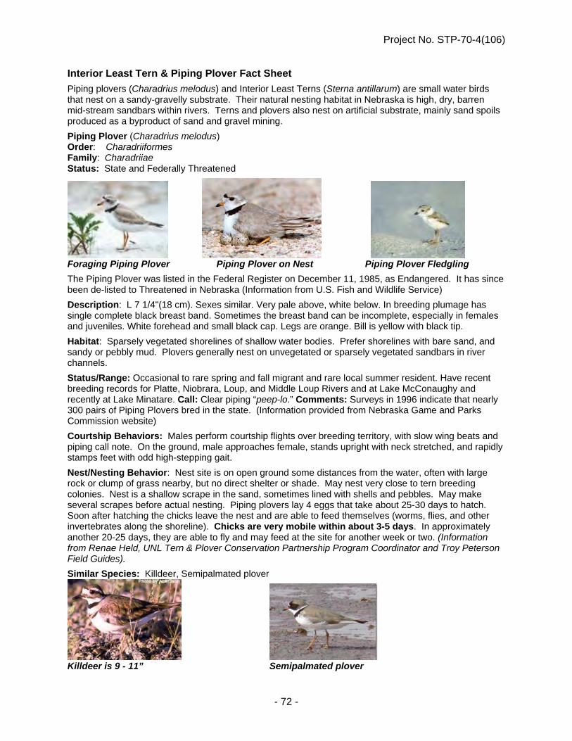
Project No. STP-70-4(106)
- 72 -
Interior Least Tern & Piping Plover Fact Sheet
Piping plovers (Charadrius melodus) and Interior Least Terns (Sterna antillarum) are small water birds that nest on a sandy-gravelly substrate. Their natural nesting habitat in Nebraska is high, dry, barren mid-stream sandbars within rivers. Terns and plovers also nest on artificial substrate, mainly sand spoils produced as a byproduct of sand and gravel mining.
Piping Plover (Charadrius melodus) Order: Charadriiformes Family: Charadriiae Status: State and Federally Threatened
Foraging Piping Plover Piping Plover on Nest Piping Plover Fledgling
The Piping Plover was listed in the Federal Register on December 11, 1985, as Endangered. It has since been de-listed to Threatened in Nebraska (Information from U.S. Fish and Wildlife Service)
Description: L 7 1/4"(18 cm). Sexes similar. Very pale above, white below. In breeding plumage has single complete black breast band. Sometimes the breast band can be incomplete, especially in females and juveniles. White forehead and small black cap. Legs are orange. Bill is yellow with black tip.
Habitat: Sparsely vegetated shorelines of shallow water bodies. Prefer shorelines with bare sand, and sandy or pebbly mud. Plovers generally nest on unvegetated or sparsely vegetated sandbars in river channels.
Status/Range: Occasional to rare spring and fall migrant and rare local summer resident. Have recent breeding records for Platte, Niobrara, Loup, and Middle Loup Rivers and at Lake McConaughy and recently at Lake Minatare. Call: Clear piping “peep-lo.” Comments: Surveys in 1996 indicate that nearly 300 pairs of Piping Plovers bred in the state. (Information provided from Nebraska Game and Parks Commission website)
Courtship Behaviors: Males perform courtship flights over breeding territory, with slow wing beats and piping call note. On the ground, male approaches female, stands upright with neck stretched, and rapidly stamps feet with odd high-stepping gait.
Nest/Nesting Behavior: Nest site is on open ground some distances from the water, often with large rock or clump of grass nearby, but no direct shelter or shade. May nest very close to tern breeding colonies. Nest is a shallow scrape in the sand, sometimes lined with shells and pebbles. May make several scrapes before actual nesting. Piping plovers lay 4 eggs that take about 25-30 days to hatch. Soon after hatching the chicks leave the nest and are able to feed themselves (worms, flies, and other invertebrates along the shoreline). Chicks are very mobile within about 3-5 days. In approximately another 20-25 days, they are able to fly and may feed at the site for another week or two. (Information from Renae Held, UNL Tern & Plover Conservation Partnership Program Coordinator and Troy Peterson Field Guides).
Similar Species: Killdeer, Semipalmated plover
Killdeer is 9 - 11” Semipalmated plover

Project No. STP-70-4(106)
- 73 -
Interior Least Tern (Sterna antillarum) Order: Charadriiformes Family: Laridae Status: State and Federally Endangered
Foraging Least Tern Least Tern with nestling Least Tern with nestling The Interior Least Tern was listed in the Federal Register as Endangered on May 28, 1985 (Information from U.S. Fish and Wildlife Service) Description: L 9" (23 cm) W 20" (51 cm). Sexes similar. Breeding adults show distinctive white forehead against black cap and nape; gray above and white below; orange-yellow bill with dark tip; orange-yellow legs. Conspicuous black wedge on outer primaries is visible in flight. Short deeply forked tail. Non-breeding birds lack black cap, instead having a dark eye stripe. Juvenile birds are mottled gray-brown above and white below. The Interior Least Tern is the smallest of all the terns. Habitat: Migrants can be found on lakes, rivers, and reservoirs. Nesting is done mainly on river sand bars or islands, but sometimes also on barren shorelines, gravel beaches, or newly cleared land. Status/Range: Uncommon spring and fall migrant in eastern part of the state. Highly local summer resident in Platte and Niobrara River valleys. Local breeder. Call: Sharp “kit, kit”, and repetitive “dee-dee”. (Information from Nebraska Game and Parks Commission website) Courtship Behaviors: In courtship, male (carrying fish in bill) flies upward, followed by female, then both glide down. On the ground, displays include courtship feeding by male. Nest/Nesting Behavior: Nest site is on open ground. Nest is shallow scrape, sometimes lined with pebbles, grass, and debris. Least terns lay 3 eggs that hatch in about 22-28 days. The chicks are fed small, whole fish by the adults even after they learn to fly. In the first few weeks the chicks move very little and tend to stay near the nest. Their defense at this age is to lie down and hide, making them vulnerable to machinery and human traffic or disturbance. (Information from Renae Held, UNL Tern & Plover Conservation Partnership Program Coordinator and Troy Peterson Field Guides) Similar Species: Common Tern or Forster’s Tern
Forster’s Tern is 14-15” Common Tern is 13-16”
Project No. STP-70-4(106)
- 74 -
Interior Least Tern and Piping Plover Survey Protocol Terns and plovers can be disturbed by sight (human figures, equipment within sight) and sound (loud equipment, banging, etc.) that are abnormal (roadway traffic is normal), therefore surveys are needed to ensure disturbance is minimized. Dates of Survey:
April 15 – August 15 If no nests are observed by July 31, then no further surveys are needed.
Time of Survey:
Prior to the start of construction, must be light enough to conduct adequate survey Record start and stop time. Survey at least 3 times a week: Monday, Wednesday, Friday
Method of Survey:
Stand at the four corners of the bridge, look 0.25 miles up and downstream of the bridge site. Use binoculars or spotting scope to survey for 20 minutes overall. Look specifically for bird movements along sandbars in the middle of the channel Other important activity to note:
Nesting- courtship behaviors, particularly copulations, birds returning to the same place, sitting on the sand for a long period of time, or nest exchange (males and females will generally take 20 minute shifts to incubate)
Foraging behavior- looking for food along sandbar, probing the sand, hovering over river channel and diving into water for fish, and bringing back fish to sandbar.
If cloudy, overcast or foggy – take additional time to ensure the best survey possible. If no nesting birds are observed, bridge work may begin accordingly. If a possible sighting occurs, then further investigation may be needed on foot. Landowner permission must be obtained if entering private land. If at any time, a nest and nesting behavior is observed within 0.25 miles of the site:
Do not start work Stop work if nest or nesting behavior is observed at times other than the morning survey Contact NDOR Environmental Section, 402-479-4464 or 402-479-3546.
NDOR Environmental will contact USFWS and NGPC for further instructions. Do not resume work at the bridge or within 0.25 mile of the abutments until NDOR Environmental
Section relays the "all clear" message to the Project Manager.

Project No. STP-70-4(106)
- 75 -
River Otter Survey Protocol Nebraska Game and Parks Commission
Background River otters were historically found in all major waterways of Nebraska. Unregulated trapping was the likely factor leading to the complete disappearance of otters from Nebraska in the early 1900’s. From 1986 to 1991, river otters were reintroduced at seven locations: South Loup River, Calamus River, North Platte River, Platte River, Cedar River, Elkhorn River and Niobrara River (Andelt 1992). Their populations have become established and have expanded from these locations. River otters are very adaptable. They typically live along wooded rivers and streams with sloughs and backwater areas and ponds. Ideal habitat has year-round open water with a plentiful food supply. Otters have been referred to as a “flagship species” for wetlands and aquatic habitats and are an indicator of wetlands with ample and high quality water (Foster-Turley 1996 and Polechla 2000) and often select sites with the least amount of human disturbance (Wilson 1959, Tabor and Wight 1977, Polechla 1990, Testa et al. 1994). Suitable habitat must also have a sufficient food source available. River otters are generalists. The primary component of their diet is fish but crustaceans are a major component of their diet in Nebraska. Fallen trees, logjams, rock piles, and other structures in the water make good habitat for the otter’s prey species and thus good habitat for the otter. Beaver dams create deep pools and slow currents that otters frequently utilize for hunting. River otters are a highly mobile species and require large amount of space to meet their annual requirements. They are active throughout the year and may occupy 50 or more miles of stream course annually (Andelt 1992) and will often move from one area to another. A single day movement was documented of 42 km (Melquist and Hornocker 1983) but daily movements are more likely less than 10km/day (Melquest et al. 2003). The social structure of river otters is not well defined and appears to vary across its geographic range (Gorman et al. 2006a), so local densities are highly variable as otters may be solitary or in small groups. While on land, otters will utilize “slides” on steep muddy or snowy banks where they slide down into the water on their bellies. When traveling any distance on a slippery surface otters are known to take a running start and then slide up to six meters (twenty feet). River otters use dens that were dug by other species such as beaver and will also utilize upland dens such as rock, brush and log piles, hollow logs, or tree root structures. They will use a variety of temporary dens and resting sites and appear to prefer sheltered sites that provide protection and seclusion (Melquist et al. 2003). A female with young pups will typically only use one natal den until the pups are sufficiently mobile and self-sufficient which may take 10 weeks. Gorman et al. 2006b found that natal dens were located in areas protected from rapid changes in water levels. Many of the dens in this study were not in the bank, but rather a distance overland and were most often located below the ground. In Nebraska, female otters enter the natal den beginning in late February through April.

Project No. STP-70-4(106)
- 76 -
Purpose River otter surveys are designed to ensure awareness and resolution to any potential conflicts between the river otters and potentially disruptive human activities. This is a highly mobile species, and if present, is likely to leave during disturbance. However, otters are especially susceptible to disturbance when they have young pups in the natal den. Den surveys, which include presence/absence surveys, are recommended and, upon consultation with the Nebraska Game and Parks Commission, may be modified from this protocol depending on the situation. These should be considered when a disturbance will be within 0.5 miles of a river, pond, sandpit, or wetland area where river otters are known to exist or are likely to be present. Den Surveys River otter dens are notoriously difficult to find and identify, as they will use dens excavated by other animals as well as brush piles, log piles and uprooted tree structures. For this reason, a den survey should begin by establishing presence/absence for the designated area. If river otters are present, a more thorough search for dens is necessary. Otters are highly mobile, and therefore, presence/absence and den surveys should be done within 10 days of the initiation of the construction activities or disturbance. It may be desirable to conduct two sets of surveys, one month or a season in advance and one within 10 days of the project beginning. Generally the survey area must include: 1. The entire area of disturbance which includes construction areas, equipment staging areas, temporary roads, etc. 2. An additional 100 yards up and down stream from the edge of the area of disturbance 3. At least 0.5 miles from the edge of the riparian/wetland area upland across the entire area of disturbance. Additional survey area may be necessary depending on the landscape context of the site. Tributaries, wetland complexes, sloughs or ponds may increase the necessary survey area.
Survey area Disturbance
100 yd up and downstream 0.5 miles from riparian area
Presence/absence can be established by identifying sign (scat, tracks, runs, rolls etc.), by finding slides or latrine sites. Otter scat will vary in size, but can generally be distinguished by fish scales. They often disintegrate into a pile of fish scales and reek of fish (Elbroch 2003). In Nebraska, scat is likely to have crayfish shells and may have bones of mammals, birds, or amphibians. Ideal latrine sites for otters in Nebraska tend to be higher areas near the edge of the water and may include sandbars, bank protrusions, rocks or logs which stick out into waterways or sites where tributaries meet a main stream or body of water. They can often be found right near the water’s edge but can also be located higher up on a bank, especially if water levels change throughout the year. Often a latrine will be located near a potential den site. Since otters repeatedly use the same latrine sites, scats will usually be abundant in one site, making them easier to find. Otter tracks are 5 to 7.5 cm (2 to 3 inches) across (Elbroch 2003).

Project No. STP-70-4(106)
- 77 -
Otter slide marks can be an easy way to identify the presence or absence of river otters. They will slip down the steep banks of a body of water and also when they travel overland across snow, ice, or mud. Bridge surveys or aerial surveys after a fresh snow are especially good times to find evidence of otter activity because the snow provides a slippery surface for an otter to slide and slides imprints can be seen in fresh snow. Otters can take a few running steps and then slide up to six meters (20 feet) on the right surfaces and slopes. Winter otter slides can be an easy way to find if otters are in the area; however, presence or absence in the winter will not preclude additional surveys immediately prior to construction (within 10 days) for these highly mobile animals. In some cases, if otters are present there may be preventative measures that can be used to prevent them from using the area prior to construction. If otters are established in the area, a thorough survey for potential den sites should be conducted. Any potential dens should be monitored to determine which species inhabits the den. Since they are highly mobile, potential dens should be re-checked 24 hours prior to initiating groundbreaking construction. If a river otter den is found in the area of the den survey, disturbance activities should not proceed or should cease and the Nebraska Game and Parks Commission should be contacted immediately. Michelle Koch, Environmental Analyst Supervisor, 402-471-5438 Sam Wilson, Furbearer Biologist, 402-471-5174 Note: River otter research is currently underway. This protocol is only valid for 1 year. If it has expired, contact the Environmental Analyst Supervisor for any updated protocols. References Andelt, R. 1992. Nebraska’s Threatened and Endangered Species: River Otter. Nebraskaland, Nebraska Game and Parks Commission, Lincoln, Nebraska. Elbroch, M. 2003. Mammal Tracks and Sign: A guide to North American species. Stackpole Books, Mechanicsburg, PA. Foster-Turley, P. 1996. Making biodiversity conservation happen: The role of environment education and communication. Environmental Education and Communication Project, U.S. Agency for International Development, Washington, DC. Gorman, T. A., J. D. Erb, B. R. McMillan and D. J. Martin. 2006a. Space use and sociality of river otters (Lontra Canadensis) in Minnesota. Journal of Mammalogy 87 (4): 740-747. Gorman, T. A., J. E. Erb, B. R. McMillan, D. J. Martin and J. A. Homyack. 2006b. Site characteristics of river otter (Lontra canadensis) natal dens in Minnesota. American Midland Naturalist 156:109-117. Melquist, W. E. and M. G. Hornocker. 1983. Ecology of river otters in west central Idaho. Wildlife Monographs 83:1-60. Melquist, W. E., P. J. Polechla, D. Toweill. 2003, River otter. Pages 708-734. In G. A. Feldhamer, B. C. Thompson and J. A. Chapman Eds., Wild Mammals of North America. John Hopkins University Press, London. Polechla, P. J. Jr. 1987. Status of the river otter (Lutra canadensis) population in Arkansas with special reference to reproductive biology. Ph.D. Dissertation, University of Arkansas, Fayetteville, Arkansas.

Project No. STP-70-4(106)
- 78 -
Poechla, P. 1990. Action plan for North American otters. Pages 74-79 in P. Foster-Turley, S. MKacdonald and C. Mason, Eds. Otters: An action plan for their conservation . Kelvyn Press, Broadview, IL. Tabor, J. E. 1977. Population status of river otter in western Oregon. Journal of Wildlife Management 41:692-699. Testa, J. W., D. F. Holleman, R. T. Bowyer, and J. B. Faro. 1994. Estimating populations of marine river otters in Prince William Sound, Alaska, using radio-tracer implants. Journal of Mammalogy 75:1021-1032. Wilson, K. A. 1959. The role of mink and otter as muskrat predators in northeastern North Carolina. Journal of Wildlife Management 18: 199-207.

Project No. STP-70-4(106)
- 79 -
Whooping Crane Fact Sheet Whooping Crane (Grus americana)
Order: Gruiformes Family: Gruidae Status: State and Federally Endangered
Whooping Cranes in Flight Foraging Whooping Cranes Adult with juvenile
The Whooping Crane (Grus americana) is a federal and state listed endangered migratory species. The Whooping Crane was federally listed as endangered in 1967. Major river systems used by whooping cranes in Nebraska include the Platte, Loup, Republican, and Niobrara rivers. Additionally, a 3-mile-wide, 56-mile-long reach of the Platte River between Lexington and Denman, Nebraska, has been federally designated as critical habitat for whooping cranes. (Information from U.S. Fish and Wildlife Service)
Description: L 52"(132 cm) W 87"(221 cm). Sexes similar but males are larger. White body with red and black facial markings. Yellow bill and long dark legs. Immature is white with tawny head and neck, and reddish-brown mottling on rest of body. Habitat: In Nebraska is found along the Platte Valley, with its wide slow moving river and associated sandbars and islands. Nearby wet meadows, croplands, and marshlands are important for foraging. Status/Range: Occasional spring and fall migrant along Platte Valley. 90% of sightings within 30 miles of Platte River, and 80% occurred between Lexington and Grand Island. Call: Shrill “ker-loo-ker-lee-loo” trumpet. Comments: Endangered. Management and protection programs slowly succeeding.
Similar: Sandhill Crane, Snow Geese, and especially American White Pelicans in flight.
(Information from Nebraska Game and Parks Commission website)
The Whooping Crane is one of the rarest birds in North America and also one of the largest. Whooping cranes are vulnerable to accidents during migration. Each spring they travel north from their wintering grounds around Aransas National Wildlife Refuge in Texas to their breeding grounds in Wood Buffalo National Park in central Canada (2,400 miles). Each fall this route is reversed. Their journey traverses eastern Montana, North Dakota, South Dakota, Nebraska, Kansas, Oklahoma and Texas. In Nebraska, they stop to rest and feed on the Platte, North and Middle Loup and Niobrara Rivers. (Information taken from the USFWS Draft Revised International Whooping Crane Recovery Plan Jan 2005)
American White Pelican

Project No. STP-70-4(106)
- 80 -
Whooping Crane Survey Protocol
Whooping Cranes can be disturbed by sight (human figures, equipment within sight) and sound (loud equipment, banging, etc.) that are abnormal (roadway traffic is normal), therefore surveys are needed to ensure disturbance is minimized.
Dates of Survey: Spring Migration – March 10 – May 10 Fall Migration – September 16 – November 16
NDOR will receive migration updates from USFWS. Surveys are to be conducted 3 times a week until Whooping Cranes are reported in South Dakota (Fall) or Kansas (Spring), then they will be required daily. If all Whooping Cranes have moved out of the area, NDOR and USFWS will consult and no further surveys may be necessary.
Bridge Projects (Roosting Survey) Time of Survey:
Prior to sunrise (published clock time) to make use of the beginning daylight hours, record start and stop time
Optional evening survey (after 4:00 p.m.) to check for birds potentially coming into roost Do east side of bridge first to reduce glare from sun.
Method of Survey: Stand at the four corners of the bridge – look at all up and down stream channels as far
as you can see Use binoculars or spotting scope Watch for at least 15 minutes overall
Look for bird movements – possibly moving within channel among vegetation Look for Whooping Cranes among Sandhill Crane groups
If cloudy, overcast or foggy and visibility is reduced to below 0.5 miles, allow time for clearing– take additional time to ensure the best survey possible
Linear Projects (Foraging Survey)-not crossing a major river Time of Survey:
Survey project within one hour of start of workday, with at least one survey done no later than 10 a.m. Record start and stop time.
Survey by driving the area of project to be worked on that day and searching fields for birds within 0.5 miles of project.
**For projects which are a combination of bridge and linear work use both methods.**
If Whooping Cranes are not seen during the morning survey, work may begin after completion of the survey.
If Whooping Cranes are spotted within 0.5 miles of the active construction: Do not start work. Stop work if seen at times other than the morning survey. Contact NDOR Environmental Section: Melissa Marinovich (402) 479-3546, or Zach
Cunningham, (402) 479-4464. Melissa Marinovich or Zach Cunningham will contact USFWS and NGPC for further
instructions. Do not resume work at the bridge or within 0.5 mile of the abutments until NDOR
Environmental Section relays the "all clear" message to the Project Manager. Work can begin or resume if birds move off; record sighting, bird departure time, and
work start time on survey form.

Project No. STP-70-4(106)
- 81 -
Project No. STP-70-4(106)
- 82 -

Project No. STP-70-4(106)
- 83 -

Project No. STP-70-4(106)
- 84 -

Project No. STP-70-4(106)
- 85 -
WETLANDS 404 PERMIT

Project No. STP-70-4(106)
- 86 -
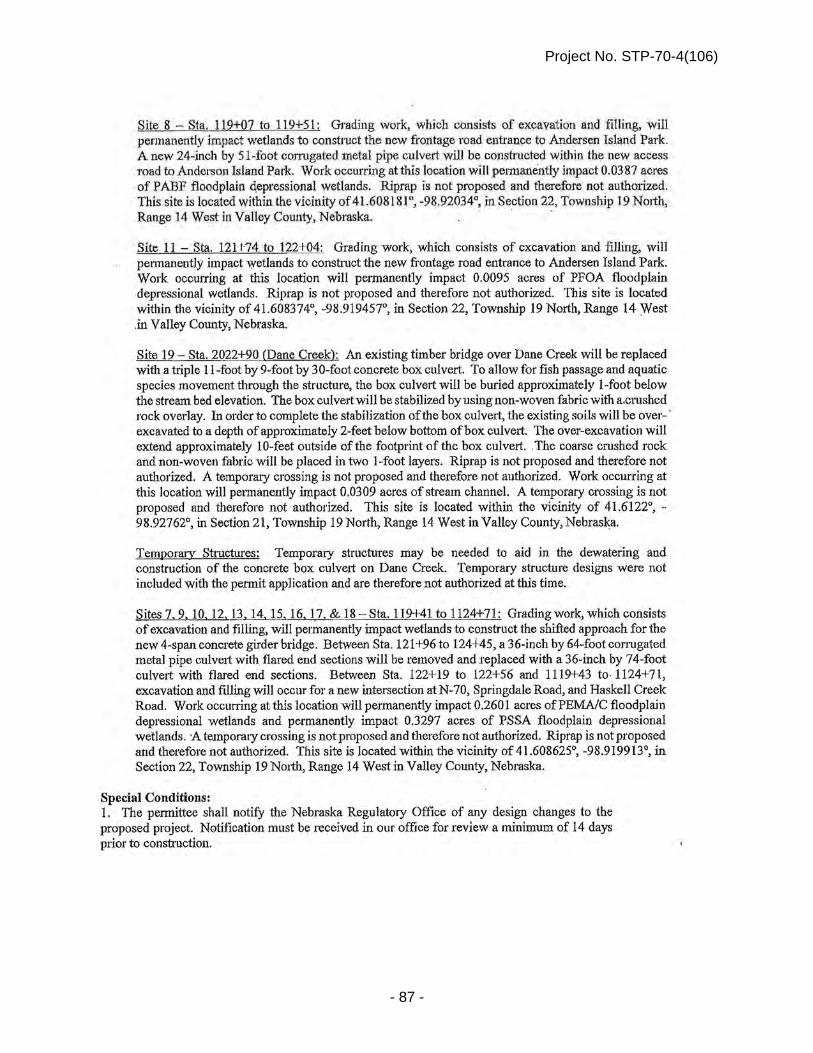
Project No. STP-70-4(106)
- 87 -

Project No. STP-70-4(106)
- 88 -

Project No. STP-70-4(106)
- 89 -

Project No. STP-70-4(106)
- 90 -

Project No. STP-70-4(106)
- 91 -

Project No. STP-70-4(106)
- 92 -

Project No. STP-70-4(106)
- 93 -

Project No. STP-70-4(106)
- 94 -
Nationwide Permit 23
Approved Categorical Exclusions
Activities undertaken, assisted, authorized, regulated, funded, or financed, in whole or in part, by another Federal agency or department where:
(a) That agency or department has determined, pursuant to the Council on Environmental Quality's implementing regulations for the National Environmental Policy Act (40 CFR part 1500 et seq.), that the activity is categorically excluded from environmental documentation, because it is included within a category of actions which neither individually nor cumulatively have a significant effect on the human environment; and
(b) The Office of the Chief of Engineers (Attn: CECW-CO) has concurred with that agency’s or department’s determination that the activity is categorically excluded and approved the activity for authorization under NWP 23. The Office of the Chief of Engineers may require additional conditions, including pre- construction notification, for authorization of an agency’s categorical exclusions under this NWP. (Sections 10 and 404) Nationwide Permit General Conditions
Note: To qualify for NWP authorization, the prospective permittee must comply with the following general conditions, as applicable, in addition to any regional or case-specific conditions imposed by the division engineer or district engineer.
1. Navigation. (a) No activity may cause more than a minimal adverse effect on navigation.
(b) Any safety lights and signals prescribed by the U.S. Coast Guard, through regulations or otherwise, must be installed and maintained at the permittee's expense on authorized facilities in navigable waters of the United States.
(c) The permittee understands and agrees that, if future operations by the United States require the removal, relocation, or other alteration, of the structure or work herein authorized, or if, in the opinion of the Secretary of the Army or his authorized representative, said structure or work shall cause unreasonable obstruction to the free navigation of the navigable waters, the permittee will be required, upon due notice from the Corps of Engineers, to remove, relocate, or alter the structural work or obstructions caused thereby, without expense to the United States. No claim shall be made against the United States on account of any such removal or alteration.
2. Aquatic Life Movements. No activity may substantially disrupt the necessary life cycle movements of those species of aquatic life indigenous to the waterbody, including those species that normally migrate through the area, unless the activity's primary purpose is to

Project No. STP-70-4(106)
- 95 -
impound water. All permanent and temporary crossings of waterbodies shall be suitably culverted, bridged, or otherwise designed and constructed to maintain low flows to sustain the movement of those aquatic species.
3. Spawning Areas. Activities in spawning areas during spawning seasons must be
avoided to the maximum extent practicable. Activities that result in the physical destruction (e.g., through excavation, fill, or downstream smothering by substantial turbidity) of an important spawning area are not authorized.
4. Migratory Bird Breeding Areas. Activities in waters of the United States that serve
as breeding areas for migratory birds must be avoided to the maximum extent practicable. 5. Shellfish Beds. No activity may occur in areas of concentrated shellfish populations,
unless the activity is directly related to a shellfish harvesting activity authorized by NWPs 4 and 48, or is a shellfish seeding or habitat restoration activity authorized by NWP 27.
6. Suitable Material. No activity may use unsuitable material (e.g., trash, debris, car
bodies, asphalt, etc.). Material used for construction or discharged must be free from toxic pollutants in toxic amounts (see Section 307 of the Clean Water Act).
7. Water Supply Intakes. No activity may occur in the proximity of a public water
supply intake, except where the activity is for the repair or improvement of public water supply intake structures or adjacent bank stabilization.
8. Adverse Effects From Impoundments. If the activity creates an impoundment of
water, adverse effects to the aquatic system due to accelerating the passage of water, and/or restricting its flow must be minimized to the maximum extent practicable.
9. Management of Water Flows. To the maximum extent practicable, the pre-
construction course, condition, capacity, and location of open waters must be maintained for each activity, including stream channelization and storm water management activities, except as provided below. The activity must be constructed to withstand expected high flows. The activity must not restrict or impede the passage of normal or high flows, unless the primary purpose of the activity is to impound water or manage high flows. The activity may alter the pre- construction course, condition, capacity, and location of open waters if it benefits the aquatic environment (e.g., stream restoration or relocation activities).
10. Fills Within 100-Year Floodplains. The activity must comply with applicable
FEMA-approved state or local floodplain management requirements. 11. Equipment. Heavy equipment working in wetlands or mudflats must be placed on
mats, or other measures must be taken to minimize soil disturbance. 12. Soil Erosion and Sediment Controls. Appropriate soil erosion and sediment
controls must be used and maintained in effective operating condition during construction, and all exposed soil and other fills, as well as any work below the ordinary high water mark or high

Project No. STP-70-4(106)
- 96 -
tide line, must be permanently stabilized at the earliest practicable date. Permittees are encouraged to perform work within waters of the United States during periods of low-flow or no-flow.
13. Removal of Temporary Fills. Temporary fills must be removed in their entirety and
the affected areas returned to pre-construction elevations. The affected areas must be revegetated, as appropriate.
14. Proper Maintenance. Any authorized structure or fill shall be properly maintained,
including maintenance to ensure public safety and compliance with applicable NWP general conditions, as well as any activity-specific conditions added by the district engineer to an NWP authorization.
15. Single and Complete Project. The activity must be a single and complete project.
The same NWP cannot be used more than once for the same single and complete project. 16. Wild and Scenic Rivers. No activity may occur in a component of the National
Wild and Scenic River System, or in a river officially designated by Congress as a “study river” for possible inclusion in the system while the river is in an official study status, unless the appropriate Federal agency with direct management responsibility for such river, has determined in writing that the proposed activity will not adversely affect the Wild and Scenic River designation or study status. Information on Wild and Scenic Rivers may be obtained from the appropriate Federal land management agency responsible for the designated Wild and Scenic River or study river (e.g., National Park Service, U.S. Forest Service, Bureau of Land Management, U.S. Fish and Wildlife Service).
17. Tribal Rights. No activity or its operation may impair reserved tribal rights,
including, but not limited to, reserved water rights and treaty fishing and hunting rights. 18. Endangered Species. (a) No activity is authorized under any NWP which is likely to
directly or indirectly jeopardize the continued existence of a threatened or endangered species or a species proposed for such designation, as identified under the Federal Endangered Species Act (ESA), or which will directly or indirectly destroy or adversely modify the critical habitat of such species. No activity is authorized under any NWP which “may affect” a listed species or critical habitat, unless Section 7 consultation addressing the effects of the proposed activity has been completed.
(b) Federal agencies should follow their own procedures for complying with the requirements of the ESA. Federal permittees must provide the district engineer with the appropriate documentation to demonstrate compliance with those requirements. The district engineer will review the documentation and determine whether it is sufficient to address ESA compliance for the NWP activity, or whether additional ESA consultation is necessary.
(c) Non-federal permittees must submit a pre-construction notification to the district engineer if any listed species or designated critical habitat might be affected or is in the vicinity of the project, or if the project is located in designated critical habitat, and shall not begin work on the activity until notified by the district engineer that the requirements of the ESA have been satisfied and that the activity is authorized. For activities that might affect Federally-listed

Project No. STP-70-4(106)
- 97 -
endangered or threatened species or designated critical habitat, the pre-construction notification must include the name(s) of the endangered or threatened species that might be affected by the proposed work or that utilize the designated critical habitat that might be affected by the proposed work. The district engineer will determine whether the proposed activity “may affect” or will have “no effect” to listed species and designated critical habitat and will notify the non- Federal applicant of the Corps’ determination within 45 days of receipt of a complete pre- construction notification. In cases where the non-Federal applicant has identified listed species or critical habitat that might be affected or is in the vicinity of the project, and has so notified the Corps, the applicant shall not begin work until the Corps has provided notification the proposed activities will have “no effect” on listed species or critical habitat, or until Section 7 consultation has been completed. If the non-Federal applicant has not heard back from the Corps within 45 days, the applicant must still wait for notification from the Corps.
(d) As a result of formal or informal consultation with the FWS or NMFS the district engineer may add species-specific regional endangered species conditions to the NWPs.
(e) Authorization of an activity by a NWP does not authorize the “take” of a threatened or endangered species as defined under the ESA. In the absence of separate authorization (e.g., an ESA Section 10 Permit, a Biological Opinion with “incidental take” provisions, etc.) from the
U.S. FWS or the NMFS, The Endangered Species Act prohibits any person subject to the jurisdiction of the United States to take a listed species, where "take" means to harass, harm, pursue, hunt, shoot, wound, kill, trap, capture, or collect, or to attempt to engage in any such conduct. The word “harm” in the definition of “take'' means an act which actually kills or injures wildlife. Such an act may include significant habitat modification or degradation where it actually kills or injures wildlife by significantly impairing essential behavioral patterns, including breeding, feeding or sheltering.
(f) Information on the location of threatened and endangered species and their critical habitat can be obtained directly from the offices of the U.S. FWS and NMFS or their world wide web pages at http://www.fws.gov/ or http://www.fws.gov/ipac and http://www.noaa.gov/fisheries.html respectively.
19. Migratory Birds and Bald and Golden Eagles. The permittee is responsible for
obtaining any “take” permits required under the U.S. Fish and Wildlife Service’s regulations governing compliance with the Migratory Bird Treaty Act or the Bald and Golden Eagle Protection Act. The permittee should contact the appropriate local office of the U.S. Fish and Wildlife Service to determine if such “take” permits are required for a particular activity.
20. Historic Properties. (a) In cases where the district engineer determines that the
activity may affect properties listed, or eligible for listing, in the National Register of Historic Places, the activity is not authorized, until the requirements of Section 106 of the National Historic Preservation Act (NHPA) have been satisfied.
(b) Federal permittees should follow their own procedures for complying with the requirements of Section 106 of the National Historic Preservation Act. Federal permittees must provide the district engineer with the appropriate documentation to demonstrate compliance with those requirements. The district engineer will review the documentation and determine whether it is sufficient to address section 106 compliance for the NWP activity, or whether additional section 106 consultation is necessary.

Project No. STP-70-4(106)
- 98 -
(c) Non-federal permittees must submit a pre-construction notification to the district engineer if the authorized activity may have the potential to cause effects to any historic properties listed on, determined to be eligible for listing on, or potentially eligible for listing on the National Register of Historic Places, including previously unidentified properties. For such activities, the pre-construction notification must state which historic properties may be affected by the proposed work or include a vicinity map indicating the location of the historic properties or the potential for the presence of historic properties. Assistance regarding information on the location of or potential for the presence of historic resources can be sought from the State Historic Preservation Officer or Tribal Historic Preservation Officer, as appropriate, and the National Register of Historic Places (see 33 CFR 330.4(g)). When reviewing pre-construction notifications, district engineers will comply with the current procedures for addressing the requirements of Section 106 of the National Historic Preservation Act. The district engineer shall make a reasonable and good faith effort to carry out appropriate identification efforts, which may include background research, consultation, oral history interviews, sample field investigation, and field survey. Based on the information submitted and these efforts, the district engineer shall determine whether the proposed activity has the potential to cause an effect on the historic properties. Where the non-Federal applicant has identified historic properties on which the activity may have the potential to cause effects and so notified the Corps, the non-Federal applicant shall not begin the activity until notified by the district engineer either that the activity has no potential to cause effects or that consultation under Section 106 of the NHPA has been completed.
(d) The district engineer will notify the prospective permittee within 45 days of receipt of a complete pre-construction notification whether NHPA Section 106 consultation is required. Section 106 consultation is not required when the Corps determines that the activity does not have the potential to cause effects on historic properties (see 36 CFR §800.3(a)). If NHPA section 106 consultation is required and will occur, the district engineer will notify the non- Federal applicant that he or she cannot begin work until Section 106 consultation is completed. If the non-Federal applicant has not heard back from the Corps within 45 days, the applicant must still wait for notification from the Corps.
(e) Prospective permittees should be aware that section 110k of the NHPA (16 U.S.C. 470h-2(k)) prevents the Corps from granting a permit or other assistance to an applicant who, with intent to avoid the requirements of Section 106 of the NHPA, has intentionally significantly adversely affected a historic property to which the permit would relate, or having legal power to prevent it, allowed such significant adverse effect to occur, unless the Corps, after consultation with the Advisory Council on Historic Preservation (ACHP), determines that circumstances justify granting such assistance despite the adverse effect created or permitted by the applicant. If circumstances justify granting the assistance, the Corps is required to notify the ACHP and provide documentation specifying the circumstances, the degree of damage to the integrity of any historic properties affected, and proposed mitigation. This documentation must include any views obtained from the applicant, SHPO/THPO, appropriate Indian tribes if the undertaking occurs on or affects historic properties on tribal lands or affects properties of interest to those tribes, and other parties known to have a legitimate interest in the impacts to the permitted activity on historic properties.
21. Discovery of Previously Unknown Remains and Artifacts. If you discover any
previously unknown historic, cultural or archeological remains and artifacts while accomplishing

Project No. STP-70-4(106)
- 99 -
the activity authorized by this permit, you must immediately notify the district engineer of what you have found, and to the maximum extent practicable, avoid construction activities that may affect the remains and artifacts until the required coordination has been completed. The district engineer will initiate the Federal, Tribal and state coordination required to determine if the items or remains warrant a recovery effort or if the site is eligible for listing in the National Register of Historic Places.
22. Designated Critical Resource Waters. Critical resource waters include, NOAA- managed marine sanctuaries and marine monuments, and National Estuarine Research Reserves. The district engineer may designate, after notice and opportunity for public comment, additional waters officially designated by a state as having particular environmental or ecological significance, such as outstanding national resource waters or state natural heritage sites. The district engineer may also designate additional critical resource waters after notice and opportunity for public comment.
(a) Discharges of dredged or fill material into waters of the United States are not authorized by NWPs 7, 12, 14, 16, 17, 21, 29, 31, 35, 39, 40, 42, 43, 44, 49, 50, 51, and 52 for any activity within, or directly affecting, critical resource waters, including wetlands adjacent to such waters.
(b) For NWPs 3, 8, 10, 13, 15, 18, 19, 22, 23, 25, 27, 28, 30, 33, 34, 36, 37, and 38, notification is required in accordance with general condition 31, for any activity proposed in the designated critical resource waters including wetlands adjacent to those waters. The district engineer may authorize activities under these NWPs only after it is determined that the impacts to the critical resource waters will be no more than minimal.
23. Mitigation. The district engineer will consider the following factors when
determining appropriate and practicable mitigation necessary to ensure that adverse effects on the aquatic environment are minimal:
(a) The activity must be designed and constructed to avoid and minimize adverse effects, both temporary and permanent, to waters of the United States to the maximum extent practicable at the project site (i.e., on site).
(b) Mitigation in all its forms (avoiding, minimizing, rectifying, reducing, or compensating for resource losses) will be required to the extent necessary to ensure that the adverse effects to the aquatic environment are minimal.
(c) Compensatory mitigation at a minimum one-for-one ratio will be required for all wetland losses that exceed 1/10-acre and require pre-construction notification, unless the district engineer determines in writing that either some other form of mitigation would be more environmentally appropriate or the adverse effects of the proposed activity are minimal, and provides a project-specific waiver of this requirement. For wetland losses of 1/10-acre or less that require pre-construction notification, the district engineer may determine on a case-by-case basis that compensatory mitigation is required to ensure that the activity results in minimal adverse effects on the aquatic environment. Compensatory mitigation projects provided to offset losses of aquatic resources must comply with the applicable provisions of 33 CFR part 332.
(1) The prospective permittee is responsible for proposing an appropriate compensatory mitigation option if compensatory mitigation is necessary to ensure that the activity results in minimal adverse effects on the aquatic environment.

Project No. STP-70-4(106)
- 100 -
(2) Since the likelihood of success is greater and the impacts to potentially valuable uplands are reduced, wetland restoration should be the first compensatory mitigation option considered.
(3) If permittee-responsible mitigation is the proposed option, the prospective permittee is responsible for submitting a mitigation plan. A conceptual or detailed mitigation plan may be used by the district engineer to make the decision on the NWP verification request, but a final mitigation plan that addresses the applicable requirements of 33 CFR 332.4(c)(2) – (14) must be approved by the district engineer before the permittee begins work in waters of the United States, unless the district engineer determines that prior approval of the final mitigation plan is not practicable or not necessary to ensure timely completion of the required compensatory mitigation (see 33 CFR 332.3(k)(3)).
(4) If mitigation bank or in-lieu fee program credits are the proposed option, the mitigation plan only needs to address the baseline conditions at the impact site and the number of credits to be provided.
(5) Compensatory mitigation requirements (e.g., resource type and amount to be provided as compensatory mitigation, site protection, ecological performance standards, monitoring requirements) may be addressed through conditions added to the NWP authorization, instead of components of a compensatory mitigation plan.
(d) For losses of streams or other open waters that require pre-construction notification, the district engineer may require compensatory mitigation, such as stream rehabilitation, enhancement, or preservation, to ensure that the activity results in minimal adverse effects on the aquatic environment.
(e) Compensatory mitigation will not be used to increase the acreage losses allowed by the acreage limits of the NWPs. For example, if an NWP has an acreage limit of 1/2-acre, it cannot be used to authorize any project resulting in the loss of greater than 1/2-acre of waters of the United States, even if compensatory mitigation is provided that replaces or restores some of the lost waters. However, compensatory mitigation can and should be used, as necessary, to ensure that a project already meeting the established acreage limits also satisfies the minimal impact requirement associated with the NWPs.
(f) Compensatory mitigation plans for projects in or near streams or other open waters will normally include a requirement for the restoration or establishment, maintenance, and legal protection (e.g., conservation easements) of riparian areas next to open waters. In some cases, riparian areas may be the only compensatory mitigation required. Riparian areas should consist of native species. The width of the required riparian area will address documented water quality or aquatic habitat loss concerns. Normally, the riparian area will be 25 to 50 feet wide on each side of the stream, but the district engineer may require slightly wider riparian areas to address documented water quality or habitat loss concerns. If it is not possible to establish a riparian area on both sides of a stream, or if the waterbody is a lake or coastal waters, then restoring or establishing a riparian area along a single bank or shoreline may be sufficient. Where both wetlands and open waters exist on the project site, the district engineer will determine the appropriate compensatory mitigation (e.g., riparian areas and/or wetlands compensation) based on what is best for the aquatic environment on a watershed basis. In cases where riparian areas are determined to be the most appropriate form of compensatory mitigation, the district engineer may waive or reduce the requirement to provide wetland compensatory mitigation for wetland losses.

Project No. STP-70-4(106)
- 101 -
(g) Permittees may propose the use of mitigation banks, in-lieu fee programs, or separate permittee-responsible mitigation. For activities resulting in the loss of marine or estuarine resources, permittee-responsible compensatory mitigation may be environmentally preferable if there are no mitigation banks or in-lieu fee programs in the area that have marine or estuarine credits available for sale or transfer to the permittee. For permittee-responsible mitigation, the special conditions of the NWP verification must clearly indicate the party or parties responsible for the implementation and performance of the compensatory mitigation project, and, if required, its long-term management.
(h) Where certain functions and services of waters of the United States are permanently adversely affected, such as the conversion of a forested or scrub-shrub wetland to a herbaceous wetland in a permanently maintained utility line right-of-way, mitigation may be required to reduce the adverse effects of the project to the minimal level.
24. Safety of Impoundment Structures. To ensure that all impoundment structures are
safely designed, the district engineer may require non-Federal applicants to demonstrate that the structures comply with established state dam safety criteria or have been designed by qualified persons. The district engineer may also require documentation that the design has been independently reviewed by similarly qualified persons, and appropriate modifications made to ensure safety.
25. Water Quality. Where States and authorized Tribes, or EPA where applicable, have
not previously certified compliance of an NWP with CWA Section 401, individual 401 Water Quality Certification must be obtained or waived (see 33 CFR 330.4(c)). The district engineer or State or Tribe may require additional water quality management measures to ensure that the authorized activity does not result in more than minimal degradation of water quality.
26. Coastal Zone Management. In coastal states where an NWP has not previously
received a state coastal zone management consistency concurrence, an individual state coastal zone management consistency concurrence must be obtained, or a presumption of concurrence must occur (see 33 CFR 330.4(d)). The district engineer or a State may require additional measures to ensure that the authorized activity is consistent with state coastal zone management requirements.
27. Regional and Case-By-Case Conditions. The activity must comply with any
regional conditions that may have been added by the Division Engineer (see 33 CFR 330.4(e)) and with any case specific conditions added by the Corps or by the state, Indian Tribe, or U.S. EPA in its section 401 Water Quality Certification, or by the state in its Coastal Zone Management Act consistency determination.
28. Use of Multiple Nationwide Permits. The use of more than one NWP for a single
and complete project is prohibited, except when the acreage loss of waters of the United States authorized by the NWPs does not exceed the acreage limit of the NWP with the highest specified acreage limit. For example, if a road crossing over tidal waters is constructed under NWP 14, with associated bank stabilization authorized by NWP 13, the maximum acreage loss of waters of the United States for the total project cannot exceed 1/3-acre.

Project No. STP-70-4(106)
- 102 -
29. Transfer of Nationwide Permit Verifications. If the permittee sells the property associated with a nationwide permit verification, the permittee may transfer the nationwide permit verification to the new owner by submitting a letter to the appropriate Corps district office to validate the transfer. A copy of the nationwide permit verification must be attached to the letter, and the letter must contain the following statement and signature:
“When the structures or work authorized by this nationwide permit are still in existence at the time the property is transferred, the terms and conditions of this nationwide permit, including any special conditions, will continue to be binding on the new owner(s) of the property. To validate the transfer of this nationwide permit and the associated liabilities associated with compliance with its terms and conditions, have the transferee sign and date below.” (Transferee) (Date)
30. Compliance Certification. Each permittee who receives an NWP verification letter from the Corps must provide a signed certification documenting completion of the authorized activity and any required compensatory mitigation. The success of any required permittee- responsible mitigation, including the achievement of ecological performance standards, will be addressed separately by the district engineer. The Corps will provide the permittee the certification document with the NWP verification letter. The certification document will include:
(a) A statement that the authorized work was done in accordance with the NWP authorization, including any general, regional, or activity-specific conditions;
(b) A statement that the implementation of any required compensatory mitigation was completed in accordance with the permit conditions. If credits from a mitigation bank or in-lieu fee program are used to satisfy the compensatory mitigation requirements, the certification must include the documentation required by 33 CFR 332.3(l)(3) to confirm that the permittee secured the appropriate number and resource type of credits; and
(c) The signature of the permittee certifying the completion of the work and mitigation.
Further Information
1. District Engineers have authority to determine if an activity complies with the terms and conditions of an NWP.
2. NWPs do not obviate the need to obtain other federal, state, or local permits, approvals, or authorizations required by law.
3. NWPs do not grant any property rights or exclusive privileges. 4. NWPs do not authorize any injury to the property or rights of others. 5. NWPs do not authorize interference with any existing or proposed Federal project.
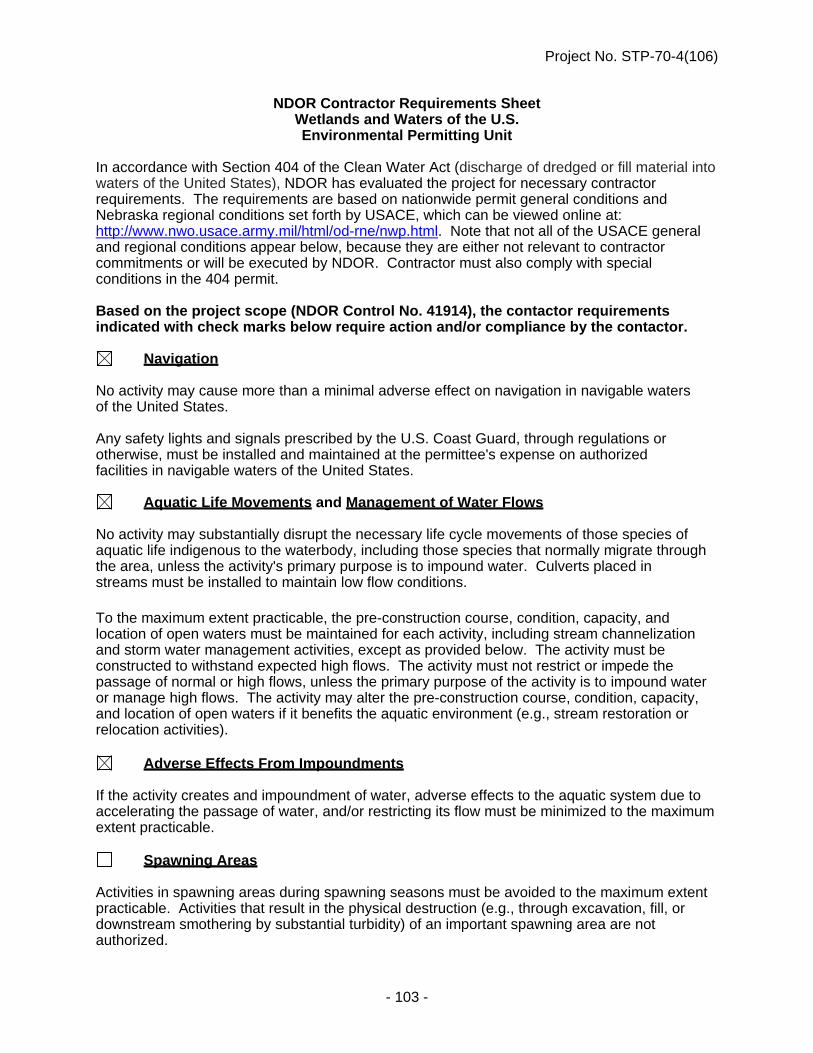
Project No. STP-70-4(106)
- 103 -
NDOR Contractor Requirements Sheet Wetlands and Waters of the U.S. Environmental Permitting Unit
In accordance with Section 404 of the Clean Water Act (discharge of dredged or fill material into waters of the United States), NDOR has evaluated the project for necessary contractor requirements. The requirements are based on nationwide permit general conditions and Nebraska regional conditions set forth by USACE, which can be viewed online at: http://www.nwo.usace.army.mil/html/od-rne/nwp.html. Note that not all of the USACE general and regional conditions appear below, because they are either not relevant to contractor commitments or will be executed by NDOR. Contractor must also comply with special conditions in the 404 permit. Based on the project scope (NDOR Control No. 41914), the contactor requirements indicated with check marks below require action and/or compliance by the contactor.
Navigation No activity may cause more than a minimal adverse effect on navigation in navigable waters of the United States. Any safety lights and signals prescribed by the U.S. Coast Guard, through regulations or otherwise, must be installed and maintained at the permittee's expense on authorized facilities in navigable waters of the United States.
Aquatic Life Movements and Management of Water Flows No activity may substantially disrupt the necessary life cycle movements of those species of aquatic life indigenous to the waterbody, including those species that normally migrate through the area, unless the activity's primary purpose is to impound water. Culverts placed in streams must be installed to maintain low flow conditions. To the maximum extent practicable, the pre-construction course, condition, capacity, and location of open waters must be maintained for each activity, including stream channelization and storm water management activities, except as provided below. The activity must be constructed to withstand expected high flows. The activity must not restrict or impede the passage of normal or high flows, unless the primary purpose of the activity is to impound water or manage high flows. The activity may alter the pre-construction course, condition, capacity, and location of open waters if it benefits the aquatic environment (e.g., stream restoration or relocation activities).
Adverse Effects From Impoundments If the activity creates and impoundment of water, adverse effects to the aquatic system due to accelerating the passage of water, and/or restricting its flow must be minimized to the maximum extent practicable.
Spawning Areas Activities in spawning areas during spawning seasons must be avoided to the maximum extent practicable. Activities that result in the physical destruction (e.g., through excavation, fill, or downstream smothering by substantial turbidity) of an important spawning area are not authorized.

Project No. STP-70-4(106)
- 104 -
Migratory Bird Breeding Areas Activities in waters of the United States that serve as breeding areas for migratory birds must be avoided to the maximum extent practicable.
Shellfish Beds No activity may occur in areas of concentrated shellfish populations, unless the activity is directly related to a shellfish harvesting activity authorized by NWPs 4 and 48.
Water Supply Intakes No activity may occur in the proximity of a public water supply intake, except where the activity is for the repair or improvement of public water supply intake structures or adjacent bank stabilization.
Equipment Heavy equipment working in wetlands or mudflats must be placed on mats, or other measures must be taken to minimize soil disturbance.
Removal of Temporary Fills Temporary fills must be removed in their entirety and the affected areas returned to pre-construction elevations. The affected areas must be revegetated, as appropriate.
Soil Erosion and Sediment Controls
SWPPP Required Appropriate soil erosion and sediment controls must be used and maintained in effective operating condition during construction, and all exposed soil and other fills, as well as any work below the ordinary high water mark or high tide line, must be permanently stabilized at the earliest practicable date. Permittees are encouraged to perform work within waters of the United States during periods of low-flow or no-flow.
Borrow Site Identification The contractor shall notify NDOR of the location of any borrow site that will be used in conjunction with the construction of the authorized activity.
Revegetation of Disturbed Areas All areas adjacent (contiguous, bordering, neighboring) to jurisdictional waters disturbed by construction shall be revegetated with appropriate perennial, native grasses and forbs and maintained in this condition. Phalaris arundinacea (Reed Canary Grass), Lythrum salicaria (Purple Loosestrife), Bromus inermus (Smooth Brome), Phragmites, sp. (Common Reed, River Reed) and Tamarix, sp. (Salt Cedar), are NOT appropriate choices of vegetation. A cover crop may be planted to aid in the establishment of native vegetation. The disturbed areas shall be reseeded concurrent with the project or immediately upon completion. Revegetation shall be acceptable when ground cover of desirable species reaches 75%. If this seeding cannot be accomplished by September 15 the year of project completion, then an erosion blanket shall be placed on the disturbed areas. The erosion blanket shall remain in place until ground cover of desirable species reaches 75%. If the seeding can be accomplished by September 15, all seeded areas shall be properly mulched to prevent additional erosion. When the vegetation has
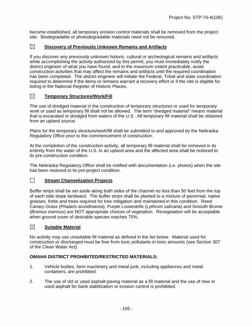
Project No. STP-70-4(106)
- 105 -
become established, all temporary erosion control materials shall be removed from the project site. Biodegradable or photodegradable materials need not be removed.
Discovery of Previously Unknown Remains and Artifacts If you discover any previously unknown historic, cultural or archeological remains and artifacts while accomplishing the activity authorized by this permit, you must immediately notify the district engineer of what you have found, and to the maximum extent practicable, avoid construction activities that may affect the remains and artifacts until the required coordination has been completed. The district engineer will initiate the Federal, Tribal and state coordination required to determine if the items or remains warrant a recovery effort or if the site is eligible for listing in the National Register of Historic Places.
Temporary Structures/Work/Fill The use of dredged material in the construction of temporary structures or used for temporary work or used as temporary fill shall not be allowed. The term “dredged material” means material that is excavated or dredged from waters of the U.S. All temporary fill material shall be obtained from an upland source. Plans for the temporary structure/work/fill shall be submitted to and approved by the Nebraska Regulatory Office prior to the commencement of construction. At the completion of the construction activity, all temporary fill material shall be removed in its entirety from the water of the U.S. to an upland area and the affected area shall be restored to its pre-construction condition. The Nebraska Regulatory Office shall be notified with documentation (i.e. photos) when the site has been restored to its pre-project condition.
Stream Channelization Projects Buffer strips shall be set aside along both sides of the channel no less than 50 feet from the top of each side slope landward. The buffer strips shall be planted to a mixture of perennial, native grasses, forbs and trees required for tree mitigation and maintained in this condition. Reed Canary Grass (Phalaris arundinacea), Purple Loosestrife (Lythrum salicaria) and Smooth Brome (Bromus inermus) are NOT appropriate choices of vegetation. Revegetation will be acceptable when ground cover of desirable species reaches 75%.
Suitable Material No activity may use unsuitable fill material as defined in the list below. Material used for construction or discharged must be free from toxic pollutants in toxic amounts (see Section 307 of the Clean Water Act). OMAHA DISTRICT PROHIBITED/RESTRICTED MATERIALS: 1. Vehicle bodies, farm machinery and metal junk, including appliances and metal
containers, are prohibited. 2. The use of old or used asphalt paving material as a fill material and the use of new or
used asphalt for bank stabilization or erosion control is prohibited.

Project No. STP-70-4(106)
- 106 -
3. The use of organic debris as fill material is prohibited. (Properly anchored trees, treetops, root wads, logs, and hay bales may be allowed on a case-by-case basis.)
4. Any material subject to leaching when in an aquatic environment is prohibited (for
example, but not limited to, chemically-treated building material, roofing material, and wood debris).
5. Individual or unanchored tires are prohibited. (Tires may be allowed on a case-by-case
basis when placed in the form of a mat or grid with multiple anchoring points to reduce the risk of design failure.)
6. Small aggregate (i.e. less than 6 inches in diameter) may not be placed below the
ordinary high water mark (OHWM) of a water body for the purpose of bank stabilization or erosion control when such aggregate will be unstable or subject to frequent failure. Small aggregate may, however, be placed below the OHWM if its purpose is to fill the interstices of a well graded rock riprap revetment or channel lining.
7. Slab material, regardless of source, must be broken before placement so that the
dimension of the largest slab will not be more than 3.5 times the dimension of the smallest slab (unless justified by a qualified engineer) and must be free of exposed rebar, wire and wire mesh.
8. The use of clean brick, broken concrete and cinder block for erosion control or bank
stabilization will be considered on a case-by-case basis. If allowed, the broken concrete must be free of exposed rebar, wire, wire mesh, asphalt paving material, paint, and other erodible materials. Broken concrete must range in size from 6 to 36 inches (unless justified by a qualified engineer).

Project No. STP-70-4(106)
- 107 -
FLOODPLAIN PERMIT

Project No. STP-70-4(106)
- 108 -
NOTICE TO BIDDERS (Storm Water Pollution Prevention Plan)
(A-20-0307)
The Contractor shall understand the terms and conditions of the general National Pollutant Discharge Elimination System (NPDES) permit that authorizes the storm water discharges associated with industrial activity from the construction site. For reference, the general permit is posted on the Department's website. Additionally, the Contractor, as evidenced by their signature on this proposal, agrees and understands that, if awarded the contract on this project, he/she:
1) becomes a co-permittee, along with the owner(s), to the Nebraska Department of Environmental Quality NPDES General Permit for Storm Water Discharges from construction sites on this project;
2) is legally bound to comply with the Clean Water Act to ensure compliance
with the terms and conditions of the storm water pollution prevention plan developed under the NPDES permit and the terms of the NPDES permit; and
3) will hold the owners harmless for damages or fines arising as a result of
noncompliance with the terms of the storm water permits and authorizations associated with the work on this project.
SPECIAL PROSECUTION AND PROGRESS (Migratory Birds)
(A-42-1112) The Department of Roads will, to the extent practicable, schedule the letting of projects such that clearing and grubbing can occur outside of the primary nesting season in Nebraska which has been determined to generally occur between April 1 and September 1. Work on structures, such as but not limited to bridges and culverts, should occur outside the primary swallow nesting season, April 15 to September 30, unless approved methods of avoiding nesting have been taken on the bridge and/or culvert structures. The nesting dates above are a guide only, nesting can occur outside of those dates. Work outside of those dates is not exempt from compliance with the Migratory Bird Treaty Act. The Contractor shall, to the extent possible, schedule work on structures, such as but not limited to bridges and culverts, and clearing and grubbing activities to occur outside the primary nesting season in Nebraska. However, if circumstances dictate that project construction or demolition must be done when nesting migratory birds may be present, a survey of the number of active nests and species of birds shall be conducted by qualified personnel representing the Contractor, and assisted by the Project Manager (PM), NDOR Environmental Section staff, or the United States Department of Agriculture (USDA) Animal and Plant Health Inspection Service (APHIS) - Wildlife Services Office. If the survey finds that nests will be impacted by the proposed construction, the Contractor may be responsible for delays.

Project No. STP-70-4(106)
- 109 -
The following guidance is provided for compliance with the Migratory Bird Treaty Act for construction of NDOR projects:
1. The Contractor shall submit a plan to the NDOR regarding how he intends to
accomplish bridge demolition or clearing and grubbing of the project to avoid conflict with nesting migratory birds.
2. The Contractor must submit a temporary erosion control plan tailored to fit the
plan for clearing and grubbing. 3. If construction operations result in unavoidable conflict with nesting migratory
bird's eggs or young, which will result in "taking" nests and their contents, the Contractor should notify the NDOR Project Manager (PM). The PM shall notify the Environmental Section of Planning and Project Development by telephone at 402-479-4766.
4. The NDOR Environmental Section will then determine if assistance in conducting
the survey will be provided by the NDOR Environmental Section (if available) or from the USDA APHIS - Wildlife Services Office and arrange for assistance with the survey of nest numbers, bird species, etc. Results of the survey shall be maintained by the NDOR until project completion.
5. If the nesting survey is required, and the project was awarded prior to the nesting
season, and the Contractor did not accomplish clearing/grubbing and/or work on bridge/culvert structures outside the nesting season, the Contractor will reimburse the Department of Roads for each survey required at $1,000 per survey. If the project was awarded during the nesting season, and construction activities are such that clearing/grubbing and/or work on bridge/culvert structures must be accomplished prior to any other activity on the project, then there will be no charge assessed for the initial survey. The Contractor is responsible for removing all trees surveyed, that do not contain active nests, and for taking appropriate measures on bridge/culvert structures, within 3 days of the survey. Reimbursement for additional surveys may be charged if the Contractor fails to remove the trees within 3 days of the survey, and requires an additional survey. Survey reimbursement will be determined on a project specific basis, considering the project timeline and associated activities.
6. If an active nest is found during the survey, the Contractor should do everything
possible to restructure his activities and leave the nest undisturbed until the young fledge. Fledging could occur within a week, or up to a month, after the survey depending on the species of bird and whether the nest contained eggs or young. Also depending on the species of bird and their sensitivity to disturbance, a buffer of up to 30 feet surrounding the tree with the active nest could be required.
7. If construction cannot be rescheduled to allow the birds to fledge, and it is
determined as an unavoidable "take" circumstance, the Contractor shall stop all work within 30 feet of the active nest and coordinate with the Construction Project Manager to determine how to proceed. The Construction Project Manager will then coordinate with the NDOR Environmental Section and they will facilitate coordination with the US Fish and Wildlife Service and the Federal Highway Administration (for projects using Federal-aid) to determine the

Project No. STP-70-4(106)
- 110 -
appropriate way to address the active nest. No work shall occur within 30 feet of the active nest until US Fish and Wildlife Service coordination is complete and the requirements of the Migratory Bird Treaty Act are satisfied.
8. It is the Contractor’s responsibility to schedule his work to accommodate the
process of conducting a survey(s) and submitting the necessary documentation if avoidance is not practicable. The Contractor shall be responsible for using any legal and practical method to prevent the nesting of birds in order to prevent the need for any survey and prevent the need for additional surveys. It is understood and agreed that the Contractor has considered in the bid all of the pertinent requirements concerning migratory birds (including endangered species) and that no additional compensation, other than time extensions if warranted, will be allowed for any delays or inconvenience resulting in these requirements.
STORM WATER DISCHARGES (A-43-0408)
In compliance with the Federal Water Pollution Control Act, authorization to discharge storm water on this project has been granted under National Pollutant Discharge Elimination System (NPDES) General NPDES Permit Number NER110000 for Storm Water Discharges from Construction Sites to Waters of the State of Nebraska. This permit became effective on January 1, 2008. Contractors are advised that, under the Construction Storm Water General Permit, plant sites, camp sites, storage sites, and borrow or waste sites not shown on the plans may be subject to separate NPDES permit authorization requirements for stormwater discharges from those locations. Contractors shall be responsible for verifying the need for NPDES permit coverage with the Nebraska Department of Environmental Quality (NDEQ). When required for these locations, the filing of a "Notice of lntent" shall be made by the Contractor directly to the NDEQ. Additionally, asphalt (SIC Code 2951) or concrete (SIC Code 3273) batch plants that are owned by a private contractor and are operated on a contract-for-service basis to perform work for the Contractor completing the project may be subject to NPDES General Permit Number NER000000 for Industrial Storm Water Discharges. While the plant may be required for completion of the project, it is not under the control of the Department (or other project owner); and the filing of a "Notice of Intent" shall be made by the Contractor directly to the NDEQ. The NDEQ may be contacted at 402-471-4220 for additional information.
REQUIRED SUBCONTRACTOR/SUPPLIER QUOTATIONS LIST (A-43-0307)
All bidders must provide to the NDOR the identity of all firms who provided quotations on all projects, including both DBEs and non-DBEs. This information must be on a form provided by the NDOR Contracts Office. If no quotations were received, the bidder must indicate this in the space provided.

Project No. STP-70-4(106)
- 111 -
Each bidder will be required to submit one list per letting to cover all projects bid.
PROPOSAL GUARANTY BID BOND (A-43-0307)
Paragraphs 1.a. and 1.b. of Subsection 102.15 in the Standard Specifications are void and superseded by the following: a. OPTION 1 - (Project Specific Paper Bid Bond). The Bid Bond shall be executed
on an original Department Bid Bond Form, which may be obtained from the Department. The original Bid Bond shall be delivered to the Department with the bid. A reproduction or a copy of the original form will not be accepted and will cause the bid not to be opened and read.
b. OPTION 2 - (Annual Bid Bond). The Department at its discretion may allow a
bidder to place an "Annual Bid Bond" on file with the Department. This bond would cover all projects the bidder bids for a 12-month period shown in the bond. The bidder must indicate in the bid submittal to the Department that their "Annual Bid Bond" applies to the submitted bid. The original Annual Bid Bond shall be executed on the Department of Roads Bid Bond Form, which may be obtained from the Department. A reproduction or a copy of the original form will not be accepted.
WORKER VISIBILITY (A-43-0507)
Pursuant to Part 634, Title 23, Code of Federal Regulations, the following modified rule is being implemented: Effective on January 1, 2008, all workers within the right-of-way who are exposed either
to traffic (vehicles using the highway for purposes of travel) or to construction equipment within the work area shall wear high-visibility safety apparel.
High-visibility safety apparel is defined to mean personal protective safety clothing that: 1 - is intended to provide conspicuity during both daytime and nighttime
usage, and 2 - meets the Performance Class 2 or Class 3 requirements of the
ANSI/ISEA 107-2004 publication titled "American National Standards for High-Visibility Safety Apparel and Headwear."

Project No. STP-70-4(106)
- 112 -
VALUE ENGINEERING PROPOSALS (VEP) (A-43-0807)
Subsection 104.03 in the Standard Specifications is amended to include the following:
14. A VEP will not be accepted if the proposal is prepared by an Engineer or the Engineering Firm who designed the contract plans.
LEGAL RELATIONS AND RESPONSIBILITY TO THE PUBLIC (A-43-0210)
Paragraph 4.a. of Subsection 107.01 in the Standard Specifications is void and superseded by the following:
4. a. Whenever the Contractor violates any governing Federal, State or Local environmental quality regulation and/or is in noncompliance with any environmental commitment, the violating activity must cease immediately until the appropriate remedy can be determined by: the Engineer, the NDOR Environmental Section, the Federal Highway Administration (for projects utilizing Federal-aid) and other agencies, as deemed appropriate. The Engineer, with assistance from the NDOR Environmental Section and the FHWA, will provide a written order confirming the appropriate corrective action to the Contractor. Work can resume to normal conditions once the Engineer determines that the violation or non-compliance has been addressed in accordance with the order for corrective action.
Subsection 107.01 in the Standard Specifications is amended to include the following two paragraphs:
5. Should the Contractor encounter any previously unidentified hazardous materials, the Engineer shall be promptly notified. The Contractor shall suspend operations in the area involved until such time that arrangements are made for their proper treatment or removal.
6. The Contractor shall prevent the transfer of invasive plant and animal species.
The Contractor shall wash equipment at the Contractor's storage facility prior to entering the construction site. The Contractor shall inspect all construction equipment and remove all attached vegetation and animals prior to leaving the construction site.
SPECIAL PROSECUTION AND PROGRESS (Federal Immigration Verification System)
(A-43-1209) The Contractor shall register with and use a Federal Immigration Verification System to determine the work eligibility status of newly hired employees physically performing services within the State of Nebraska. The Prime Contractor shall contractually require every subcontractor to register with and use a Federal Immigration Verification System to determine

Project No. STP-70-4(106)
- 113 -
the work eligibility status of newly hired employees physically performing services within the State of Nebraska. The Federal Immigration Verification System shall be an electronic verification of the work authorization program of the Illegal Immigration Reform and Immigration Responsibility Act of 1996, 8 U.S.C. 1324a, known as the E-Verify Program. The Contractor may use an equivalent Federal program designated by the United States Department of Homeland Security or other Federal agency authorized to verify the work eligibility status of a newly hired employee. The equivalent program shall comply with the Immigration Reform and Control Act of 1986. The Prime Contractor shall furnish a letter to the NDOR Construction Division in Lincoln on company letterhead and signed by an officer of the company stating that documentation is on file certifying that the Contractor and all subcontractors have registered with and used a Federal Immigration Verification System. The Contractor shall maintain all records of registration and use for a period of three years and make records available upon request. The Contractor shall contractually require subcontractors to maintain all records for a period of three years and make records available upon request. Payment will not be made to the Contractor for using the Federal Immigration Verification System or the maintenance of the records. This work shall be subsidiary to the work being performed. The Contractor’s Certification shall become part of the final records of the Contract. The Department considers this document to have direct bearing to the beginning interest date and may affect the amount of interest earned.
CONTRACT TIME ALLOWANCE (A-43-0911)
Paragraph 5. of Subsection 108.02 of the Standard Specifications is void and superseded by the following: 5. Each week, the Engineer shall post on the Department’s website a report of
working days or calendar days charged. The Contractor then has 14 days from the day the Engineer’s report is posted to provide a written explanation of why he/she does not concur with the working days or calendar days as assessed.
Paragraph 6.b. of Subsection 108.02 of the Standard Specifications is amended to include the following: (4) If the time allowance for the contract has been established on a calendar day
basis, the Contractor is expected to schedule the work and assign whatever resources are necessary to complete the work in the time allowance provided regardless of the weather. Accordingly, regardless of anything to the contrary contained in these Specifications, the Department will not consider delays caused by inclement or unseasonable weather as justification for an extension of the contract time allowance unless:
i. the weather phenomena alleged to have contributed to or caused
the delay is of such magnitude that it results in the Governor issuing a Disaster Declaration, and

Project No. STP-70-4(106)
- 114 -
ii. the weather phenomena alleged to have contributed to or caused the delay can clearly be shown to have directly impacted the work on the critical path identified on the Contractor’s schedule.
Paragraphs 10.b. and 10.c. of Subsection 108.02 of the Standard Specifications are void and superseded by the following: b. (1) If the extra work is not in the original contract, time extensions will be
granted by determining the actual time necessary to accomplish the extra work.
(2) If the extra work is the result of the addition of additional quantities of
existing contract items, time extensions will be granted by either: (i) determining the actual time necessary to accomplish the extra
work; or
(ii) determining the additional time to be granted by comparing the value of the additional quantities of work to the total amount of the original contract when measurement of the actual additional time is not possible or practical.
(3) In either case, only the time necessary to perform the extra work of the
additional quantities of existing contract items when the extra work or the additional quantities of existing contract items are deemed to be the current controlling operation will be granted as a time extension.
c. Increases in quantities of work associated with traffic control items measured by
the day will not be considered for extending the contract time allowance. Overruns of traffic control items that are measured by methods other than time may be considered for extending the contract time allowance, but they must be deemed to be a controlling operation when the overrun of quantities occurs.
PARTIAL PAYMENT (A-43-1110)
Paragraph 2. of Subsection 109.07 of the Standard Specifications is void and superseded by the following: 2. When the value of the work completed during a semi-monthly period exceeds
$10,000, the Contractor will receive semi-monthly progress estimates from which the Department shall make such retentions as may be allowed by the contract, provided that the nature and quality of the completed work are satisfactory and provided further that the progress of the work conforms to the requirements of Subsection 108.07.
Paragraph 3.b. of Subsection 109.07 of the Standard Specifications is void and superseded by the following: b. Under normal circumstances, the Department shall not retain any earnings on a
progress estimate. However, the Department reserves the right to retain such

Project No. STP-70-4(106)
- 115 -
amounts as are necessary for material deficiencies, anticipated liquidated damages, unpaid borrow, and for other reasons to protect the Department’s interests.
PARTIAL PAYMENT (A-43-0611)
Paragraph 4. of Subsection 109.07 of the Standard Specifications is void and superseded by the following: 4. a. (1) Upon presentation by the Contractor of receipted bills, billing invoices, or
such other documentation sufficient to satisfy the Engineer and verify the Contractor’s or subcontractor’s actual costs for the materials, payments may also be allowed for acceptable nonperishable materials purchased expressly to be incorporated into the work and delivered in the vicinity of the project or stored in acceptable storage places within Nebraska.
(2) Materials not delivered and stored in the immediate vicinity of or on the
actual project site must be clearly marked to identify the project on which they are to be used, must be segregated from similar materials at the storage site, and cannot be included in a supplier’s inventory of material available for sale for other purposes.
(3) All items eligible for partial payment as stored materials must be available
for verification, sampling, and measurement. b. The amount to be included in the payment will be determined by the Engineer,
but in no case shall it exceed 100 percent of the value of the materials documented. This value may not exceed the appropriate portion of the value of the contract item or items in which such materials are to be incorporated, nor shall the quantity in any case exceed the total estimated quantity required to complete the project.
c. Payment will not be approved when the documented value of such materials
amounts to less than $1,000.00, when the progress of the work is not in accordance with the requirements set forth in Subsection 108.07, or when the material can reasonably be expected to be incorporated into the work and eligible for payment as completed work on a progress estimate within 15 days of being placed into storage.
d. Deductions at rates and in amounts which are equal to the payments will be
made from estimates as the materials are incorporated into the work. e. Payment for the materials shall not in itself constitute acceptance, and any
materials which do not conform to the specifications shall be rejected in accordance with Subsection 106.05.
f. The Contractor shall be responsible for all damages and material losses until the
material is incorporated into the work and the work is accepted.

Project No. STP-70-4(106)
- 116 -
g. Partial payment will not include payment for fuels, supplies, form lumber, falsework, other materials, or temporary structures of any kind which will not become an integral part of the finished construction.
h. No partial payments will be made on living or perishable plant materials until
planted.
BUY AMERICA (A-43-0212)
Subsection 106.07 in the Standard Specifications is void and superseded by the following: 106.07 -- Buy America 1. The Buy America rule requires that steel or iron materials be produced
domestically, and only those products which are brought to the construction site and permanently incorporated into the completed project are covered. Construction materials, forms, etc., which remain in place at the Contractor's convenience, but are not required by the contract, are not covered.
2. To further define the coverage, a domestic product is a manufactured steel
construction material that was produced in one of the 50 States, the District of Columbia, Puerto Rico, or in the territories and possessions of the United States.
3. All manufacturing processes to produce steel or iron materials (i.e., smelting, and
any subsequent process which alters the steel or iron material's physical form or shape, or changes its chemical composition) must occur within one of the 50 States, the District of Columbia, Puerto Rico, or in the territories and possessions of the United States, to be considered of domestic origin. This includes processes such as casting, rolling, extruding, machining, bending, grinding, drilling, and coating. Coating includes epoxy coating, galvanizing, painting, and any other coating that protects or enhances the value of the material. The manufacturer shall include a statement on the material test report or certification that all material described above except the coating material is a domestic product.
4. Raw materials used in the steel or iron materials may be imported. All
manufacturing processes to produce steel or iron materials must occur domestically. Raw materials are materials such as iron ore, limestone, waste products, etc., which are used in the manufacturing process to produce the steel products. Waste products would include scrap; i.e., steel no longer useful in its present form from old automobiles, machinery, pipe, railroad tracks and the like. Also, steel trimmings from mills or product manufacturing are considered waste. Extracting, crushing, and handling the raw materials which is customary to prepare them for transporting are exempt from Buy America. The use of pig iron and processed, pelletized, and reduced iron ore manufactured outside of the United States may be used in the domestic manufacturing process for steel and/or iron materials.

Project No. STP-70-4(106)
- 117 -
5. Notwithstanding this requirement, a minimum of foreign steel or iron materials will be permitted if its value is less than one-tenth of one percent of the total contract cost or $2,500, whichever is greater.
6. Upon completion of all work utilizing steel or iron products, the Prime Contractor
shall furnish a letter to the State on company letterhead and signed by an officer of the company stating that documentation is on file certifying that all steel or iron materials brought to the construction site and permanently incorporated into the work complied in all respects with the Buy America requirements.
BORROW, WASTE, STOCKPILE, AND PLANT SITE APPROVAL (A-43-0512)
Subsection 107.02 in the Standard Specifications is amended to include the following: 4. Site Approval: a. When borrow is obtained from a borrow site or waste excavation is placed
at sites which are not shown in the contract, or the Contractor plans to use a plant or stockpile site which is not shown in the contract, the Contractor shall be solely responsible for obtaining all necessary site approvals. The Department will provide the procedures necessary to obtain approvals from the U.S. Army Corps of Engineers, U.S. Fish and Wildlife Service, Nebraska State Historical Society, Nebraska Game and Parks Commission, and Nebraska Department of Natural Resources on the NDOR website. The Contractor shall also be responsible for obtaining a Discharge Number from the Nebraska Department of Environmental Quality (NDEQ) that allows work under the current Construction Stormwater Permit. The Contractor shall also be responsible for obtaining any and all other permits required by local governments.
b. It is anticipated that it may require 60 calendar days or more for the
Contractor to obtain the necessary approvals. The Contractor will not be allowed to begin work at borrow or waste sites until the necessary approvals are obtained. No extension of completion time will be granted due to any delays in securing approval of a borrow or disposal site unless a review of the time frames concludes that there were conditions beyond the Contractor’s control.
Paragraph 7. of Subsection 205.02 in the Standard Specifications is void and superseded by the following: 7. Borrow and Waste Site Approval: a. Borrow and waste site approvals shall be in accordance with
Section 107.02. b. Material shall not be removed from borrow sites until preliminary cross
sections and representative soil samples have been taken by the Engineer. The Contractor shall notify the Engineer a sufficient time in

Project No. STP-70-4(106)
- 118 -
advance of the opening of any borrow site so that cross sections may be taken.
c. Material shall be removed in a manner that will allow accurate final cross
sections to be taken for determining the quantity of excavation. The surfaces of the borrow sites shall be bladed and shaped to drain as shown in the contract or as directed by the Engineer.
SPECIAL PROSECUTION AND PROGRESS (Subletting or Assigning of Contract)
(A-43-0414) Subsection 108.01 in the Standard Specifications is void and superseded by the following: 108.01 – Subletting or Assigning of Contract 1. a. (1) The Contractor will not be allowed to sublet, assign, sell, transfer, or
otherwise dispose of any portion of the contract or any right, title, or interest therein; or to either legally or equitably assign any of the money payable under the contract or the claims without the prior written consent of the Engineer.
(2) With the Engineer’s consent, the Contractor may sublet up to 70 percent
of the work.
(3) Any items designated in the contract as “specialty items” may be performed by subcontract.
(4) The cost of any subcontracted “specialty items” may be deducted from
the total contract cost before computing the percentage of work required to be performed by the Contractor.
(5) Subcontracts, or transfer of contract, will not release the Contractor of any
liability under the contract and bonds. b. Certain items of work may be performed without a subcontract. A list of items not
requiring a subcontract is available from the Engineer. 2. The performance of any work by a subcontractor before the date of authorization
by the Department shall subject both the Contractor and subcontractor to the imposition of appropriate sanctions by the Department.
3. a. The Contractor’s request to sublet work shall be made electronically to the NDR
Construction Engineer using project management software identified by the Department. A signed subcontract agreement shall be on file in the Contractor’s office when the request is made. The subcontract agreement must provide that the subcontracted work will be completed according to the terms of the contract. The required and Special Provisions contained in the proposal shall be physically included in any subcontract.

Project No. STP-70-4(106)
- 119 -
b. On all Federal-aid projects, a scanned copy (.pdf format) of the signed subcontract agreement shall be included with the subcontracting request. (Federal-aid projects can be identified by inclusion in the Proposal of Form FHWA-1273 (REQUIRED CONTRACT PROVISIONS FEDERAL-AID CONSTRUCTION CONTRACTS).
c. Scanned copies (.pdf format) of all executed subcontracts, written agreements,
and/or lease agreements used to meet DBE goals shall be submitted to the NDR Construction Engineer with the subcontracting request. These copies must show labor cost, material prices, overhead and profit.
4. a. Second tier subcontracts will be allowed. b. If a DBE firm subcontracts work to another firm, only work subcontracted to
another DBE firm can be counted toward meeting a DBE goal. c. All requests for second tier subcontracting shall be submitted to and approved by
the Prime Contractor before they are forwarded to the NDR Construction Engineer for approval.
5. All subcontract documents relating to the contract shall be maintained during the
course of the work and preserved for a period of three years thereafter. These documents shall be available for inspection by authorized representatives of State and Federal agencies. Scanned copies (.pdf format) of the signed subcontract agreements not specifically identified elsewhere in this Subsection shall be furnished to the Department upon request.
6. The Contractor may discuss a proposed subcontract with the Engineer before
entering into a signed subcontract agreement, but final approval will not be granted until a formal request and proper certification has been received by the Department.
7. On projects requiring submittal of certified payrolls, all subcontractor payrolls
shall be checked by the Contractor before submittal to the Engineer. 8. a. The Prime Contractor, and subcontractors when subletting work to lower tier
subcontractors, shall include language which can be identified as a “Prompt Payment Clause” as a part of every subcontract for work and materials.
b. (1) The language constituting the “Prompt Payment Clause” will require
payment to all first tier subcontractors for all labor and materials --- for work completed to date --- within 20 calendar days of receipt of progress payments from the Department for said work. Similar language in a contract between a subcontractor and a lower-tier subcontractor will require payment to the lower tier subcontractor for all labor and materials --- for work completed to date --- within 10 calendar days of receipt of progress payments from the prime Contractor for said work.
(2) The language constituting the “Prompt Payment Clause” will also stipulate
the return of retainage within 30 calendar days after the satisfactory completion of the work by the subcontractor as evidenced by inclusion of the work on a progress payment.

Project No. STP-70-4(106)
- 120 -
(3) Additionally, the language constituting the “Prompt Payment Clause” may
stipulate the subcontractor’s obligation to return to the Contractor or subcontractor, as the case may be, any overpayments which result from adjustments to measured and recorded quantities as part of the preparation of subsequent progress payments or the final records. Overpayments shall be returned to the Prime Contractor or subcontractor, as the case may be, within 20 calendar days of receiving notice of the adjusted quantities and the amount of the overpayment.
c. The Prime Contractor of subcontractors, as the case may be, may withhold
payment only for just cause and shall not withhold, delay, or postpone payment without first receiving written approval from the Department.
d. (1) The failure by the Prime Contractor to abide by the agreements identified
in the “Prompt Payment Clause” without just cause, including the timely return of retainage, is a material breach of this contract which may result in the Department withholding the amount of payment from the prime Contractor that should have been paid to the subcontractor, termination of this contract, or other such remedy as the Department deems necessary.
(2) Additionally, the failure of any subcontractor to abide by the agreements
identified in the “Prompt Payment Clause” without just cause, including the timely return of retainage to lower tier subcontractors, or by failing to return overpayments in a timely manner when the language permitted in Paragraph 8.b.(3) above is included in the subcontract may result in the Department withholding subcontract approval for other work until the overpayments have been returned.
9. a. (1) For Davis Bacon (DBRA)-covered projects and Non-DBRA-covered
projects, a Contractor or subcontractor may wish to use another individual owner-operator or trucking company to supplement his or her hauling fleet. (The Department will not recognize multiple individuals claiming to be collectively identified as a single “owner operator.)
(2) This supplemental individual or company must either become a
subcontractor (first tier or lower tier, as the case may be) or be otherwise documented by the utilizing Contractor or subcontractor by entering into a lease agreement for the trucks and showing the driver (or drivers) from the supplemental company on the Prime Contractor’s or subcontractor’s payrolls in the manner described below.
(3) Payrolls will only be accepted from the Prime Contractor or approved
subcontractors.
b. (1) If the decision is made to subcontract the hauling, the Prime Contractor must first notify the NDOR Construction Office to request subcontract approval. As part of the subcontract approval process --- at any tier --- the proper certificates of insurance must be provided before approval will be granted.
(2) Additionally, on DBRA-covered projects, the Prime Contractor must submit payrolls for all subcontractors --- at any tier.

Project No. STP-70-4(106)
- 121 -
c. (1) Owner/Operators of trucks hired by a Contractor or subcontractor to
supplement his or her hauling fleet are not subject to Davis Bacon wage requirements. However, they must still be shown on a payroll prepared by the Contractor or subcontractor for whom they are working with the notation “owner/operator.”
(2) Any other employees of the “owner/operator” must appear on the certified
payroll in complete detail and must be compensated according to the wage rates established for the project.
d. In the event a Prime Contractor or subcontractor elects to not subcontract the
supplemental driver or drivers but instead chooses to “carry the workers/truckers on their payroll,” the following requirements must be met:
(1) The Prime Contractor’s or subcontractor’s certified payroll must contain
the names of all workers/truck drivers, and the payroll should identify their supervisors (including “owner-operators”).
(2) Pay checks for the workers/truckers in question must be drawn against
the Prime Contractor’s or subcontractor’s payroll or other account. (3) Owner/Operators need only be identified as such on the payroll.
Additional drivers, if any, from the “owner-operator’s” company must appear on a payroll in complete detail and be compensated according to the wage rates established for the project.
(4) The Prime Contractor or subcontractor must enter into a lease agreement
for the trucks driven by such drivers, and the lease agreement must show that the compensation for the leased equipment is on a time basis and not based on the amount of work accomplished. The lease agreements must be available for inspection by NDOR personnel.
(5) Any supplemental truckers employed under this arrangement must still
carry the minimum automobile liability coverage specified in the contract. It shall be the duty of the Prime Contractor to ensure that the supplemental truckers have such coverage in effect. Evidence of proper insurance must be presented for verification on demand.
ELECTRONIC SHOP DRAWINGS (A-43-0215)
Paragraphs 5, 6, and 7 of Subsection 105.02 of the Standard Specifications are void and superseded by the following: 5. a. The Contractor shall provide electronic working drawings in a Portable Document
Format (PDF). The PDFs shall be sized to print on an 11x17 inch sheet of paper and have a minimum resolution of 300 dpi. Each sheet of the shop drawings shall have a space provided for an electronic stamp that measures 2.5 inches x 3.5 inches when printed.

Project No. STP-70-4(106)
- 122 -
b. Electronic working drawing files shall be named with the following file naming format:
Control Number_Brief Description_Date.pdf For example: 12345_FloorDrains_05Feb2015 12345_FloorDrainCoverLetter_05Feb2015 c. The project number, control number, and project location as it appears on the
plans shall be shown on the front sheet of each Shop Drawing file. Structure numbers shall be included, if applicable.
6. No electronic working drawings shall be submitted to the Engineer unless they
have been checked by the Contractor. The electronic submittal shall be accompanied by a Contractor’s letter of approval in a PDF format. This letter shall also be named with the format shown in the example above. The letter of approval shall clearly indicate that the Contractor is responsible for any errors on the working drawings.
7. a. Electronic submittals shall be submitted by email to the following address: [email protected] b. Attachments shall be limited to 25 MB of data per email. Larger files shall be
separated and sent in multiple emails. c. Electronic working drawings will only be accepted from the Prime Contractor. 8. Any reference to hard copy shop drawings in the contract shall be considered
void.
LIABILITY INSURANCE (A-55-0414)
Subsection 107.13 in the Standard Specifications is void and superseded by the following: 107.13 – Liability Insurance
Prior to execution of the contract, the Contractor shall obtain insurance coverage to fully protect it from loss associated with the work, and have at a minimum the insurance described below: 1. General Liability: Limits of at least:
$ 1,000,000 per Occurrence $ 2,000,000 General Aggregate $ 2,000,000 Completed Operations Aggregate $ 1,000,000 Personal and Advertising Injury
a. Contractor shall be responsible for the payment of any deductibles.

Project No. STP-70-4(106)
- 123 -
b. Coverage shall be provided by a standard form Commercial General
Liability Policy (CG0001 or equivalent) covering bodily injury, property damage including loss of use, and personal injury.
c. The General Aggregate shall apply on a Per Project Basis. d. The State of Nebraska, Department of Roads, shall be named as an
Additional Insured on a primary and non-contributory basis including completed operations for three (3) years after final acceptance and payment.
e. Contractor agrees to waive its rights of recovery against the State of
Nebraska, Department of Roads. Waiver of Subrogation in favor of the State of Nebraska, Department of Roads shall be added to the policy.
f. Contractual liability coverage shall be on a broad form basis and shall not be amended by any limiting endorsements.
g. If work is being performed near a railroad track, the 50' railroad right-of-
way exclusion must be deleted. h. Products and completed operations coverage in the amount provided
above shall be maintained for the duration of the work, and shall be further maintained for a minimum period of three years after final acceptance and payment.
i. Coverage shall be included for demolition of any building or structure,
collapse, explosion, blasting, excavation and damage to property below surface of ground (XCU coverage).
j. Policy shall not contain a total or absolute pollution exclusion. Coverage
shall be provided for pollution exposures arising from products and completed operations as per standard CG0001 Pollution Exclusion or equivalent. If the standard pollution exclusion as provided by CG0001 has been amended, coverage must be substituted with a separate Pollution Liability policy of $1.0 million per occurrence and $2.0 million aggregate. If coverage is provided by a “claims made” form, coverage will be maintained for three years after project completion. Any applicable deductible is the responsibility of the Contractor.
2. Automobile Liability: Limits of at least: $ 1,000,000 CSL per Accident
a. Coverage shall apply to all Owned, Hired, and Non-Owned Autos. b. If work is being performed near a railroad track, the 50-foot railroad right-
of-way exclusion must be deleted. c. Contractor agrees to waive its rights of recovery against the State of
Nebraska, Department of Roads. Waiver of Subrogation in favor of the State of Nebraska, Department of Roads, shall be added to the policy.

Project No. STP-70-4(106)
- 124 -
d. Automobile liability coverage shall be obtained from an insurance carrier
who is licensed with the Nebraska Department of Insurance.
3. Workers’ Compensation: Limit: Statutory coverage for the State where the project is located.
Employer’s Liability limits: $500,000 Each Accident $500,000 Disease – Per Person $500,000 Disease – Policy Limit
a. Contractor agrees to waive its rights of recovery against the State of Nebraska, Department of Roads. Waiver of Subrogation in favor of the State of Nebraska, Department of Roads shall be added to the policy.
b. Workers’ compensation coverage shall be obtained from an insurance
carrier who is licensed with the Nebraska Department of Insurance. c. Where applicable, the Longshore and Harborworkers Compensation Act
endorsement shall be attached to the policy.
4. Umbrella/Excess: Limits of at least: $1,000,000 per Occurrence a. Policy shall provide liability coverage in excess of the specified Employers
Liability, Commercial General Liability and Automobile Liability. b. The State of Nebraska, Department of Roads, shall be an “Additional
Insured.” c. Contractor agrees to waive its rights of recovery against the State of
Nebraska, Department of Roads. Waiver of subrogation in favor of the State of Nebraska, Department of Roads shall be provided.
5. Pollution Liability:
a. When “hazardous wastes” or contaminated or polluted materials must be handled and/or moved, the Contractor shall obtain Pollution Liability Coverage with minimum limits of $1,000,000 per occurrence and $2,000,000 aggregate.
b. If, during the course of construction, hazardous wastes, contaminated or
polluted material are discovered on the project, the Contractor shall immediately cease any operation that may disturb these materials, and shall immediately notify the Engineer of all facts related to the discovery of these materials.
c. Unforeseen work related to the discovery of hazardous, contaminated or
polluted materials on the project, and the extra cost, if any, of pollution liability coverage will be handled as “extra work.”

Project No. STP-70-4(106)
- 125 -
6. Additional Requirements:
a. The Contractor shall provide and carry any additional insurance required by the Special Provisions.
b. Except as otherwise provided herein, all insurance shall be kept in full
force and effect until after the State releases the Contractor from all obligations under the contract.
c. (1) If any of the work is sublet, equivalent insurance shall be provided
by or on behalf of the subcontractor or subcontractors (at any tier) to cover all operations.
(2) Approved trucking subcontractors (at any tier) who are being
utilized only for the purpose of hauling materials shall be exempt from the requirements of Paragraphs 1, 4, and 5.
(3) (i) When a Contractor or subcontractor chooses to employ a trucker
by carrying the driver on his or her payroll and entering into a lease agreement for the truck, the owner-operator of the truck shall be required to comply with the Automobile Liability provisions of Paragraph 2.
(ii) Furthermore, it shall be the duty of the Prime Contractor to ensure
that the owner-operator of the truck has such insurance in effect. The Prime Contractor shall maintain evidence that any truckers so utilized (at any tier) are insured to the minimum limits specified and be able to furnish documentation of the same on demand.
(iii) Failure to ensure that insurance coverage exists and failure to
maintain evidence thereof shall be considered a breach of the contract.
d. Any insurance policy shall be written by an insurance company with a
Best’s Insurance Guide Rating of A – VII or better. e. Prior to execution of the contract, Contractor shall provide the State of
Nebraska, Department of Roads, evidence of such insurance coverage in effect in the form of an Accord (or equivalent) certificate of insurance executed by a licensed representative of the participating insurer(s). Certificates of insurance shall show the Nebraska Department of Roads as the certificate holders.

Project No. STP-70-4(106)
- 126 -
f. For so long as insurance coverage is required under this agreement, the Contractor shall have a duty to notify the Department when the Contractor knows, or has reason to believe, that any insurance coverage required under this agreement will lapse, or may be cancelled or terminated. The Contractor must forward any pertinent notice of cancellation or termination to the Department at the address listed below by mail (return receipt requested), hand-delivery, or facsimile transmission within 2 business days of receipt by Contractor of any such notice from an insurance carrier. Notice shall be sent to:
Nebraska Department of Roads Construction Division --- Insurance Section 1500 Highway 2, P.O. Box 94759 Lincoln, NE 68509-4759 Facsimile No. 402-479-4854 g. Failure of the owner or any other party to review, approve, and/or reject a
certificate of insurance in whole or in part does not waive the requirements of this agreement.
h. The limits of coverage set forth in this document are suggested minimum
limits of coverage. The suggested limits of coverage shall not be construed to be a limitation of the liability on the part of the Contractor or any of its subcontractors/tier subcontractors. The carrying of insurance described shall in no way be interpreted as relieving the Contractor, subcontractor, or tier subcontractors of any responsibility or liability under the contract.
i. If there is a discrepancy of coverage between this document and any
other insurance specification for this project, the greater limit or coverage requirement shall prevail.
CONSTRUCTION DETAILS
FUEL COST ADJUSTMENT PAYMENT (B-1-0708)
Paragraph 16.a. of Subsection 205.05 in the Standard Specifications is amended to provide that the references to fuel cost fluctuation will be 5% instead of the 10% shown. The fuel use factor, "F", shown in Paragraph 16.c. of Subsection 205.05 is void and superseded by the following:
F = English
The fuel use factor for diesel fuel, in gallons per cubic yard. For the items of work "Excavation", "Excavation, Borrow", and "Excavation, Established Quantity", "F" shall be equal to 0.20. For the item of work "Earthwork Measured in Embankment", "F" shall be equal to 0.27.

Project No. STP-70-4(106)
- 127 -
Metric The fuel use factor for diesel fuel, in liters per cubic meter. For the items of work "Excavation", "Excavation, Borrow", and "Excavation, Established Quantity", "F" shall be equal to 0.99. For the item of work "Earthwork Measured in Embankment", "F" shall be equal to 1.32.
Paragraph 16.d. of Subsection 205.05 is void and superseded by the following:
d. The allowable price differential, "D", for the current estimate will be computed
according to the following formula: When the current price, P, is greater than the base price, P(b). D = P - 1.05P(b), but not less than zero. When the current price, P, is less than the base price, P(b). D = P - 0.95P(b), but not greater than zero.
WATER (B-1-0307)
Paragraph 4.a. of Subsection 205.04 in the Standard Specifications is amended to include the following: Payment shall be made at the established contract unit price.
EXCAVATION AND EMBANKMENT (B-1-0212)
Paragraph 6. of Subsection 205.02 in the Standard Specifications is void and superseded by the following: 6. Frozen Layers:
a. Thin Frozen Layer. A thin soil layer that freezes during the construction of an embankment may remain provided that the layer:
(i) had proper density and moisture prior to freezing, (ii) can be readily broke up by a single pass of a tamping
(sheepsfoot) roller or track mounted excavator, (iii) is thoroughly scarified into pieces having a single dimension of 3
inches or less, and a second dimension of ½ inch or less, and (iv) is not within 10 inches (measured vertically) of any thin frozen
layer that was previously scarified and left in place.

Project No. STP-70-4(106)
- 128 -
b. Thick Frozen Layer. A soil layer that freezes during the construction of an
embankment, but does not meet the Thin Frozen Layer requirements:
(i) may remain in the embankment provided that the layer is thawed and has proper density and moisture after thawing, or
(ii) shall be completely removed from the embankment prior to
placing any additional embankment material.
TEMPORARY WATER POLLUTION CONTROL (B-3-1014)
Section 204 in the Standard Specifications is void.
CONSTRUCTION STORMWATER MANAGEMENT CONTROL (B-3-1014)
A. General
1. This Section defines some best management practices (BMPs) for erosion and sediment control measures and construction practices the Contractor shall use to prevent soil erosion and avoid water pollution.
2. a. The Department and the Contractor are co-permittees of the NPDES
Construction Storm Water General Permit.
b. The Contractor shall comply with all conditions required by the current NPDES Construction Storm Water General Permit.
3. The Contractor shall exercise every reasonable precaution throughout the life of
the contract to prevent silting of the waters of the state, the project site, and adjacent property. Construction of drainage facilities, as well as performance of other contract work which will contribute to the control of siltation, shall be carried out in conjunction with earthwork operations or as soon thereafter as is practicable.
4. a. The Contractor shall take sufficient precautions to prevent pollution of the
waters of the state, the project site, and adjacent property from construction debris, petroleum products, chemicals, or other harmful materials.
The Contractor shall conduct and schedule the operations to avoid
interference with any protected species. b. The Contractor shall comply with all applicable statutes relating to
pollution of the waters of the state and fish and game regulations.

Project No. STP-70-4(106)
- 129 -
5. All construction debris shall be disposed in a manner that it cannot enter any waterway. Excavation shall be deposited as to protect the waters of the state from siltation.
6. All erosion and sediment control measures shall be properly installed and
maintained by the Contractor until all permanent drainage facilities have been constructed, and all slopes are sufficiently vegetated to be an effective erosion deterrent; or until tentative acceptance of the work.
7. All erosion and sedimentation resulting from the Contractor's operations and the
weather conditions must be corrected by the Contractor.
LIMITATION OF OPERATIONS (B-3-1014)
A. General
1. The maximum exposed surface area for the Contractor's operations in excavation, borrow, and embankment is 18 acres (72,800 m2) plus an equal area of clearing and grubbing/large tree removal. A written request for an increase in the maximum exposed surface area may be approved by the Engineer. This approval will be based on the soil, moisture, seasonal conditions, the Contractor’s operation, or other conditions.
2. The Engineer shall have the authority to reduce the maximum exposed surface
area when any of the following conditions warrant:
a. Soil and moisture conditions are such that erosion is probable.
b. Seasonal conditions may force extended delays.
c. Proximity to the waters of the state requires more stringent controls.
d. Equipment and personnel available on the job is not sufficient to properly maintain erosion and dust control measures.
e. Any other environmental condition in the area that may exist which would
be affected by erosion from the project. 3. Construction operations in rivers, streams, wetlands, and impoundments shall be
restricted to those areas specifically shown in the contract. Rivers, streams, wetlands, and impoundments shall be promptly cleared of all false work, piling, debris, or other obstructions placed therein or caused by the construction operations.
4. Fording and operation of construction equipment within streams and wetlands
will not be allowed, unless explicitly allowed in the contract. Streams are defined as any area between the high banks, regardless of the flow conditions.
Project No. STP-70-4(106)
- 130 -
CONSTRUCTION METHODS (B-3-1014)
A. General
1. The Contractor shall conduct all construction activities and install temporary erosion control measures, as necessary, to control sediment and avoid soil erosion during construction.
2. The Contractor shall incorporate all permanent erosion control features into the
project at the earliest practicable time. 3. Construction stormwater management control measures for Contractor obtained
work areas located outside the right-of-way, such as borrow site operations, haul roads, plant sites, staging sites, waste sites, equipment storage sites, etc. are the sole responsibility of the Contractor. All construction stormwater management control measures for these areas are at the Contractor’s expense. The Contractor is responsible for securing all required permits for use of these sites.
4. The construction stormwater management procedures contained herein shall be
coordinated with any permanent erosion control measures specified elsewhere in the contract to the extent practical to assure economical, effective, and continuous erosion and sediment control throughout the construction period.
5. The Contractor shall be responsible to limit erosion and prevent siltation into the
waters of the state during the construction period, as well as during the times that work may be suspended.
6. a. All erosion and sediment control items shall be installed by personnel who
are knowledgeable in the principles and practice of various BMP installations.
b. The installation of all erosion and sediment control items shall be done
under the direct supervision of the Contractor’s employee who has successfully completed training provided by the Department and has been certified as an Erosion and Sediment Control Inspector (Inspector). The Contractor’s Inspector shall be present at each site during installation to direct and inspect all erosion and sediment control BMP installations.
i. The NDOR Erosion and Sediment Control Inspector Certification
is obtained by completing an Erosion and Sediment Control Inspector Training Course provided by the Nebraska Department of Roads and passing the examination that accompanies the training.
c. The Contractor shall notify the Engineer of all employees, who have been
certified as Inspectors, who will be on the project to direct and inspect all erosion and sediment control BMP installations.
d. No payment will be made for any erosion and sediment control item
unless a Contractor’s Inspector was present to directly supervise and inspect the work.

Project No. STP-70-4(106)
- 131 -
e. No payment will be made for any erosion and sediment control item that
is not properly installed. All erosion and sediment control items shall be installed as per the contract.
ENVIRONMENTAL COMMITMENT DOCUMENT (B-3-1014)
A. Environmental Commitment Document 1. a. An Environmental Commitment Document will be created by the
Department to identify all project specific environmental commitments and will be included in the Contract.
b. The Department will provide information for the following, when
applicable: i. Storm Water Pollution Prevention Plan (SWPPP)
ii. U.S. Army Corps of Engineers (USACE) Section 404 Permit
iii. Nebraska Department of Environmental Quality 401 Water Quality Certification
iv. State Title 117 Waters (USACE Non-Jurisdictional)
v. Floodplain Permit
vi. Historic Clearance
vii. Endangered Species Act Clearance
viii. Nebraska Nongame and Endangered Species Conservation Act Clearance
ix. National Environmental Policy Act Compliance
x. NPDES Construction Stormwater Permit (within Right-of-Way limits, only)
xi. Conservation Measures
xii Migratory Bird Treaty Act
xiii. Bald and Golden Eagle Protection Act Compliance
xiv. Other pertinent issues
c. The Contractor shall provide information for the following, when
applicable: i. Temporary Erosion Control Plan
ii. Spill Prevention and Control Plan
iii. Migratory Bird Treaty Act Compliance Plan
iv. Name and telephone number of the Contractor’s representative responsible for the Environmental Commitments

Project No. STP-70-4(106)
- 132 -
v. Name and telephone number of the employees that are NDOR-Certified Erosion and Sediment Control Inspectors
vi. Critical Path Construction Schedule
vii. Other items as defined elsewhere in the contract
STORM WATER POLLUTION PREVENTION PLAN (SWPPP) (B-3-1014)
A. General 1. A SWPPP is required for projects that construction activities will cause a land
disturbance of one (1) acre or more. The Department will prepare the SWPPP for the areas within the Right-of-Way, temporary easements and permanent easements.
2. For projects not requiring a SWPPP, the Contractor shall comply with the
requirements of Environmental Commitment Document, Paragraph 1.b. of this Special Provision, as applicable.
3. Contractor obtained work areas, located on private property, are not included in
the NDOR Project SWPPP. B. Temporary Erosion Control Plan 1. The Contractor shall prepare and submit the Temporary Erosion Control Plan
prior to the start of any work. The Contractor shall not begin work until the Temporary Erosion Control Plan has been submitted to the Engineer and appropriate erosion control measures are in place. Payment for any work on the contract will be withheld if erosion control measures are not in place or properly maintained.
2. The Temporary Erosion Control Plan will be reviewed at project progress
meetings. All active Contractors shall have their Inspectors present and work in cooperation to determine any necessary changes. Necessary changes will be documented on the Temporary Erosion Control Plan by the Engineer.
3. Payment for preparing the Temporary Erosion Control Plan, inspections and
meeting reviews are subsidiary to items that direct payment is made. C. Spill Prevention and Control Plan 1. All project activities shall be addressed in the Spill Prevention and Control Plan.
The Contractor shall prepare and submit the plan to the Engineer and install all appropriate spill prevention and control measures prior to the start of any work.
2. The Spill Prevention and Control Plan shall clearly state measures to prevent,
contain, document and clean up a spill. It shall state measures for disposal of the contaminated material, disposal documentation and incident review to train personnel to prevent spills from reoccurring.

Project No. STP-70-4(106)
- 133 -
3. Spill Prevention and Control Plans are applicable to construction sites where
hazardous materials are stored, used and/or generated onsite. Hazardous materials include, but not limited to: hazardous wastes, pesticides, paints, cleaners, petroleum products, fertilizers, solvents and porta-potty wastes.
4. Direct payment will not be made for the Spill Prevention and Control Plan. D. Migratory Bird Treaty Act Compliance Plan 1. The Contractor shall not begin work until a Migratory Bird Treaty Act Compliance
Plan has been submitted to the Engineer and appropriate nesting migratory bird avoidance measures are in place.
2. a. The Contractor shall clearly state the necessary measures they intend to
use to avoid a “Take” of nesting migratory birds in the Migratory Bird Treaty Act Compliance Plan. Measures may include but are not limited to:
i. Clearing and grubbing prior to April 1st or after September 1st
ii. Tree removal prior to April 1st or after September 1st
iii. Clearing empty nests on structures prior to April 1st
iv. Maintaining clear structures until commencement and throughout the duration of work on structures
v. Netting structures to prevent nesting
vi. Commitment to perform surveys according to protocol
vii. Hire a biologist to survey areas to be disturbed prior to commencement of work during the nesting season
viii. Submittal of required bird survey reports
ix. Training of Contractor Personnel to insure compliance
3. a. The Migratory Bird Treaty Act Compliance Plan is applicable to the entire
project site to avoid the “Take” of migratory birds protected under the Migratory Bird Treaty Act.
b. “Take” is defined as: pursuit, hunt, shoot, wound, kill, trap, capture,
collect, or attempt to pursue, hunt, shoot, wound, kill, trap, capture, or collect.
4. The Migratory Bird Treaty Act Compliance Plan shall adhere to the NDOR’s
Avian Protection Plan located at: http://www.transportation.nebraska.gov/environment/guides/avian-protection-
plan.pdf Direct payment will not be made for the Migratory Bird Treaty Act Compliance
Plan.

Project No. STP-70-4(106)
- 134 -
E. SWPPP Inspection 1. The Contractor shall accompany the Engineer on inspections in accordance with
the NPDES Construction Storm Water General Permit. 2. The SWPPP will be maintained and updated by the Engineer as work progresses
and site conditions change to accurately describe the BMPs that are currently in place.
3. The Contractor’s participation in SWPPP inspections, maintenance and updates
shall begin on the first day construction activities cause land disturbance and end on the date of project completion as evidenced as the completion date in the District Engineer’s Letter of Tentative Acceptance.
4. a. The Contractor’s Inspector shall be responsible for ensuring that all BMPs
are installed in accordance with the contract or the manufacturers’ recommendations. The Contractor’s Inspector shall be capable of reading and interpreting these documents.
b. The Contractor’s Inspector shall be familiar with product and structural
BMPs. The Contractor’s Inspector shall inspect, assess, and supervise the maintenance of erosion and sediment control BMPs to ensure compliance with the NPDES Construction Storm Water General Permit while preserving BMP functionality.
5. Payment for project inspection is subsidiary to items that direct payment is made.
ENVIRONMENTAL COMMITMENT ENFORCEMENT (B-3-1215)
A. General 1. This specification establishes payment and disincentive assessment for the
Contractor’s performance in complying with Contract Environmental Commitments.
2. Deficiencies are described but not limited to: a. Failure to install pollution prevention control BMPs as work progresses or
as described in the SWPPP. b. Failure to maintain existing pollution prevention control BMPs. c. Failure to remove non-functioning pollution prevention control BMPs. d. Failure to comply with USACE Section 404 Permit requirements. e. Failure to comply with NPDES Construction Storm Water General Permit
requirements.

Project No. STP-70-4(106)
- 135 -
f. Failure to comply with all applicable statutes relating to pollution of the waters of the state.
g. Exceeding the maximum exposed surface area for excavation of 18 Acres
without written request for permission and written approval. h. Failure to comply with wildlife species specific conservation conditions. i. Failure to comply with the Contract. j. Failure to comply with the Engineers directives. B. SWPPP Deficiency Notification 1. The Engineer will document and direct the Contractor to correct deficiencies. 2. a. The Contractor shall commence correcting deficiencies, provide adequate
equipment and personnel, and diligently pursue correcting deficiencies without cessation until all deficiencies have been corrected.
b. The count of Working Days and/or Calendar Days will continue during the
time period that corrective work is being performed. c. Delays to the project as a result of the Contractor conducting corrective
actions for the Contract Environmental Commitments will not constitute a valid reason for an extension of the contract time allowance.
3. Deficiencies shall be corrected within seven (7) calendar days of notification or
within an approved extension. When deficiencies are not corrected within seven (7) calendar days or within an approved extension, the Engineer will make a disincentive assessment to the contract as stated herein.
4. a. If soil, weather, or other conditions prevent the Contractor from
completing the corrective actions within seven (7) calendar days, the Contractor shall notify the Engineer in writing. The Contractor’s letter shall state the reasons preventing corrective action within the time allowed. The Contractor shall propose a written Corrective Action Plan within 48 hours. Corrective work shall continue while the Corrective Action Plan is developed. The Contractor’s Corrective Action Plan must contain a course of action and a time frame for completion. If the reasons and the Corrective Action Plan are acceptable, the Engineer may extend the time in which to complete the corrective work.
b. The Contractor will be allowed to proceed with the plan as proposed
without incurring a disincentive assessment. If all corrective work is completed within the time allowance shown in the Notification or within an approved extension, a disincentive assessment will not be imposed upon the Contractor.
c. Storm events or soil and weather conditions occurring on other projects,
which interfere with a Contractor completing corrective actions on the

Project No. STP-70-4(106)
- 136 -
project within seven (7) calendar days, will not be justification for a time extension to complete the corrective work.
5. If all corrective work identified in the Notification has not been completed at the
end of the seventh (7th) calendar day after the Initial Notice Date or within an approved extension, a Shut-Down Notice will be issued on the eighth (8th) calendar day after the Initial Notice Date or on the calendar day following the last day of an approved extension.
6. All operations shall cease as of the date and time cited in the Shut-Down Notice.
The Contractor shall work, exclusively, on the deficiencies until all have been corrected or as directed by the Engineer. Upon issuance of the Shut-Down Notice, a disincentive of $500.00 per deficiency per calendar day will be assessed thru the day the corrective work is completed, inclusive.
7. The Engineer may require the Contractor to provide a written Procedures Plan
that describes the process to prevent reoccurrence of deficiencies. The written Procedures Plan shall be provided within two (2) calendar days of the request. Failure to correct all deficiencies and provide a Procedures Plan may result in payments being withheld until such time that procedures are outlined.
a. Payment for preparing a written Procedures Plan is subsidiary to items
that direct payment is made. C. Storm Event Restoration – Incentive and Disincentive 1. The Department will pay “Storm Event Restoration - Incentive” when the
Contractor completes the restoration work to eliminate the pollution prevention control deficiencies within seven (7) calendar days of Notification or within an approved extension. Multiple deficiencies may be included in one notification. If the restoration work has not been completed within seven (7) calendar days after the Initial Notice or within an approved extension, payment for the item of “Storm Event Restoration - Incentive” will not be made.
2. A storm event is defined as a storm exceeding 0.50 inch of rain in a 24 hour
period. 3. The Department will notify the Contractor of pollution prevention control
deficiencies. 4. a. Payment for the item of “Storm Event Restoration - Incentive” may not be
made when the Contractor is notified to correct pollution prevention devices not installed in accordance with the contract or the manufacturer’s recommended installation instructions.
5. If the restoration work is not completed within seven (7) calendar days or within
an approved extension, a disincentive assessment of $500.00 per deficiency per calendar day will be assessed. The disincentive assessment will begin on the eighth (8th) calendar day after the issuance of the Initial Notice Date or on the calendar day following the last day of an approved extension(s) and continue through the day that the restoration work is completed, inclusive.

Project No. STP-70-4(106)
- 137 -
D. Method of Measurement 1. a. “Storm Event Restoration – Incentive” will be measured by the each upon
completion of restoration of all deficiencies included in a notification within the allowed time and only one payment per notification is allowed when multiple deficiencies are included on the notification.
b. If deficiencies from multiple notifications are restored during the same
restoration operation, only one (1) incentive is eligible for payment. c. If multiple notifications are the result of successive storm events and
deficiencies are transferred to ensuing notifications, incentive payment is only eligible for the latest notification.
2. “Storm Event Restoration – Disincentive” will be measured by the calendar day in
accordance with Paragraph C.5. above. E. Basis of Payment 1. Pay Item Pay Unit Storm Event Restoration – Incentive Each Storm Event Restoration – Disincentive Calendar Day 2. All equipment, materials, etc. used in the restoration work will be paid for in
accordance with Division 800 of the Standard Specifications. 3. Payment is full compensation for all other incidentals required to complete the
restoration work included in the notification within the allowed time. F. Environmental Commitments – Contractor Compliance 1. To provide payment for all plans, inspections, surveys, reports, travel, qualified
inspection person’s, carrion removal, and any other subsidiary activities for the work of implementing threatened and endangered species commitments, temporary erosion control or any other environmental commitments prescribed in the contract.
2. Multiple visits to the project may be required to comply with environmental
commitments prescribed in the contract. G. Method of Measurement 1. No measurement is required. H. Basis of Payment 1. Pay Item Pay Unit Environmental Commitments – Contractor Compliance Lump Sum

Project No. STP-70-4(106)
- 138 -
2. Partial payments will be made as follows: a. The Department will pay 50 percent of the total amount bid for the item
Environmental Commitments – Contractor Compliance within seven (7) calendar days after the Notice to Proceed Date.
b. Upon completion of 50 percent of the Original Contract Amount, the
Department will pay 30 percent of the amount bid for the item Environmental Commitments – Contractor Compliance.
c. Upon completion of 75 percent of the Original Contract Amount, the
Department will pay the remaining 20 percent of the amount bid for the item Environmental Commitments – Contractor Compliance.
d. Failure to comply with any or all of the contract requirements, included for
payment under the item of Environmental Commitments – Contractor Compliance, will preclude all payment for the item, including any previous payment.
3. Payment is full compensation for all work prescribed in the contract. I. Immediate Action Deficiencies 1. Deficiencies that pose an imminent threat to the environment are considered an
emergency situation. These deficiencies will be identified in the Immediate Action Deficiencies Section of the Environmental Commitment Deficiency Notification Form. The corrective work for Immediate Action Deficiencies shall begin immediately and continue without cessation until completed.
2. The Engineer will issue a shut-down notice. All work on the contract shall cease
until the corrective work has been completed. The Engineer may allow the Contractor to continue working in areas unaffected by the Immediate Action Deficiency, provided corrective actions are being actively performed on the deficiency.
3. Immediate Action Deficiencies are not eligible for an incentive payment. 4. The Contractor will be assessed a disincentive assessment of $1,000.00 per
deficiency per calendar day for failure to begin corrective actions or failing to continue to completion as directed by the Engineer or by the regulatory agency with jurisdiction.
5. Examples of Immediate Action Deficiencies include but are not limited to: a. Threatened & Endangered Species habitat protection deficiencies b. USACE Section 404 Permit Noncompliance c. Petroleum Spills/Tank Leakage d. Hazardous Material Spills

Project No. STP-70-4(106)
- 139 -
J. Rights Reserved 1. The Department reserves the right to initiate and perform corrective action on
any deficiencies which result from the Contractors’ actions, inactions, or for failure to comply with the NPDES Construction Stormwater General Permit, USACE Section 404 Permit, or any other applicable permit.
2. The Contractor shall be liable to the Department for any and all costs incurred by
the Department for corrective actions taken by the Department. 3. It is expressly understood that the provisions of this specification shall not relieve
the Contractor of their responsibilities nor shall it relieve the Surety of its obligation for and concerning any just claim.
4. The Contractor shall indemnify and save harmless the Department and all of its
representatives from any and all actions or claims brought because of the Contractor’s actions, inactions, or for failure to comply with the NPDES Construction Storm Water General Permit, USACE Section 404 Permit, or any other applicable permit.
ACCEPTANCE TESTING OF SOILS BY USE OF THE LIGHT WEIGHT DEFLECTOMETER (LWD) SCOPE
(B-4-0915) This test method covers the in-place measurement of deflection and moisture content of Class III embankments, subgrade preparation, granular fill and backfill for acceptance testing on Nebraska Department of Roads Projects. Refer to Subsection 205.03 of the NDOR Standard Specifications for Highway Construction for a definition of Class III embankments. Refer to NDR Test Method T 2835 for the proper operation of the LWD. The deflection test measurement shall be the average measured deflection of the fourth, fifth, and sixth drops of the falling weight of the LWD. The first three drops are to be used to seat the LWD. The Deflection Target Value (DTV) is the deflection value of each soil determined by using a test strip or from correlation with the Nebraska Group Index for an individual Soil. Option 1 A. Determination of DTV using a Test Strip 1. A test strip shall be constructed for each soil type to determine the deflection
target value. 2. A new test strip shall be constructed when there is an observed change in
material or as determined by the Engineer. 3. The test strip dimensions for roadway embankment and subgrades shall have a
minimum length of 200 feet and a width equal to the embankment or roadway.

Project No. STP-70-4(106)
- 140 -
The total thickness shall be no less than 6 inches for roadway subgrade and no less than 1 foot and no more than 3 feet for roadway embankment.
4. The test strip dimensions for trenches, culverts, and structures shall have a
minimum length of 10 feet and a width equal to that of the excavation. The total thickness shall be no less than 1 foot and no more than 3 feet.
5. The optimum moisture of fine grained soils shall either be determined in the
NDOR Branch Lab or Central Lab, and shall be based on a correlation with the Plastic Limit or determined from AASHTO T-99. A 10-lb sample of proposed material shall be submitted to the NDOR Branch Lab or Central Lab a minimum of 14 days prior to grading operations.
6. The moisture content for granular soils shall be “as necessary” to achieve proper
compaction. 7. The moisture content limits of the soil shall follow the requirements provided in
Table 1. 8. The test strip area construction shall be incidental to the embankment
construction. 9. The testing rate during the test strip construction is provided in Table 2.

Project No. STP-70-4(106)
- 141 -
Table 1 - Moisture Requirements
Location Soil Type Depth Below
Finished Subgrade
Minimum % Maximum %
Soil materials receiving concrete
pavement
Silt – Clay Silt- Clay Granular
Upper 3 feet Greater than 3 feet
All Depths
Opt. -3 Opt. -3
**
Opt. +2 Opt. +2
** Soil materials
receiving flexible pavement
Silt – Clay Silt- Clay Granular
Upper 3 feet Greater than 3 feet
All Depths
Opt. -2 Opt. -3
**
Opt. +1 Opt. +2
** Soil materials
receiving gravel surfacing
All materials All Depths ** **
Subgrade prep. Shoulder subgrade
prep (concrete pavement)
Silt – Clay
Granular
The upper 6 inches of subgrade
soil
Opt. -3
**
Opt +2
**
Subgrade prep. Shoulder subgrade
prep (flexible pavement)
Silt – Clay
Granular
The upper 6 inches of subgrade
soil
Opt. -2
**
Opt +1
**
Stabilized Subgrade
- - See Specifications
Granular Structural Fill (MSE Walls, bridges, culverts,
et.)
Granular All Depths ** **
** Moisture as necessary to obtain proper compaction. The moisture target value for granular materials shall be established in the field by the Contractor during the compaction process. Once established the target moisture shall not vary by more than + 2%.
Table 2 - Test Strip Testing Rate Material Location Minimum Testing Rate
Roadway embankment and subgrade 3 tests/ pass* Trenches, culverts, and miscellaneous structures 1 test / pass*
* Number of passes with compaction equipment as described in paragraph 14c of Subsection 205.03 of the NDOR Standard Specifications for Highway Construction. B. Test Strip Construction and Testing 1. Prior to placing the fill material for the test strip, the subgrade shall be scarified
and re-compacted. 2. The fill material shall be placed with a lift thickness no greater than 8 inches
uncompacted. 3. The test strip shall be constructed with uniform material and moisture content,
and compaction; until it meets the requirements of numbers 3 or 4 of Section A of this provision.

Project No. STP-70-4(106)
- 142 -
4. The deflection target value is obtained when: i. The moisture content is within the acceptable range.
ii. The average of the deflection test measurements for three consecutive passes of compaction equipment does not change by more than 10% with additional compaction. The DTV shall be based on the lowest average deflection test measurement from these passes.
5. A 10-lb sample of the test strip material shall be submitted to the NDOR Branch
Lab or Materials and Research Soil Lab for index testing. 6. The DTV shall be re-evaluated when: i. Deflection test measurements are consistently less than the DTV. (3 out
of 5 consecutive deflection test measurements are less than 0.80 of the DTV).
ii. Failing test results are consistently occurring and adequate compaction is observed.
Option 2 C. Determination of Deflection Target Values based on the Nebraska Group Index
(NGI) 1. Prior to construction a 10-lb bag of representative material shall be submitted to
the nearest NDOR Branch Lab or Materials and Research Soil Lab for each different soil type no less than 21 days prior to grading operations.
2. From the laboratory testing NDOR will determine the Nebraska Group Index
(NGI) for each soil type submitted and provide a correlated minimum DTV and optimum moisture content.
3. If no correlation data is available for an individual NGI, a test strip shall be used
to determine the DTV as discussed in parts A and B in this provision. 4. The DTV shall be re-evaluated when: i. Deflection test measurements are consistently less than the DTV. (More
than 20% of the deflection test measurements are less than 0.80 of the DTV.
ii. Failing test results are consistently occurring and adequate compaction is observed.
Project No. STP-70-4(106)
- 143 -
Acceptance Testing 1. The Deflection Target Value for use as acceptance testing shall be: DTV ≤ 1.10 x average deflection value determined from Option 1, Part B,
of this provision
DTV ≤ Correlated DTV determined from the NGI correlation, Option 2, Part C
2. The testing frequency for moisture and deflection shall follow the NDOR
Materials Sampling Guide. 3. The moisture content of soil shall be performed using NDOR’s approved
equipment and methods. Approved equipment includes: 1) hot plates, stove, or microwave, 2) Speedy Moisture Method, or 3) Laboratory oven method.
4. Moisture content results shall be reported to the nearest tenth of a percent.
SAWING PAVEMENT
Paragraph 5. of Subsection 203.04 in the Standard Specifications is void.
WETLAND MITIGATION (Post-Grading Survey)
The construction of the wetland mitigation site will require the Contractor to conduct a post-grading land survey, submit the survey results, and obtain approval from the Department. Tree/shrub planting and/or seeding activities MAY NOT PROCEED until approval of survey results is obtained from the Department. The project horizontal and vertical coordinates shall be used for the survey based on the Nebraska State Plane Coordinate System. See plans for datum information. The survey should be conducted after the mitigation site detail/finish grading is complete. The surveyor shall show adequate break lines and random points to insure that the DTM accurately reflects the surface of the earth. Great care shall be taken in the development of break lines in the area of structures, channel features, tree/shrub planting areas, and wetland depressions. Break lines at both the top and bottom of vertical features present shall be developed. Random points are generally collected in a gridded manner with a nominal spacing of about 25 to 50 feet. This spacing can vary widely, however, the maximum spacing shall be 50 feet. The spacing and placement of random points shall be such as to insure the accuracy of the DTM. The Contractor shall provide the Department the Geopak survey folder with all output files and data collector files for post-processing. The Department will review the processed survey results against the design plans. It is anticipated that the survey results should be within 0.25 foot vertically and 2 feet horizontally of the design plans to ensure approval. A written approval or denial will be submitted to the Contractor within 45 days of submittal of land survey results. If approval is denied, areas needing corrective work will be specified. These areas must be surveyed again after corrective work and re-submitted for the Department approval process. Corrective work must gain written approval prior to seeding or planting activities. The survey

Project No. STP-70-4(106)
- 144 -
and submittal process should be discussed at a pre-construction meeting with the Contractor(s) and NDOR Staff. The post-grading land survey shall be considered as included in the Lump Sum item “Construction Staking and Surveying” shown in the Bid Proposal schedule of items. Any survey work required for corrective work shall be at no additional cost to the Department.
CONSTRUCTION AND OBLITERATION OF TEMPORARY ROADS AND TEMPORARY DRAINAGE
Temporary Roads The earthwork required to construct the temporary road is included in the pay quantity of Excavation shown in Group 1. When the temporary road is no longer required, it shall be obliterated by the grading contractor. The surfacing shall be removed, the embankment removed, and the area graded to the design cross sections. The removal of the temporary surfacing is included in the cost of the placing the temporary surfacing as prescribed elsewhere in these Special Provisions. The work of obliterating the embankment shall be paid for as "Excavation (Established Quantity)". Temporary Junction Boxes and Storm Sewer Pipe The quantities to build the temporary junction boxes are included in the items “Class 47B-3000 Concrete For Inlet And Junction Box”, “Reinforcing Steel For Inlet And Junction Box” and “Cast Iron Cover and Frame”. The quantity of temporary storm sewer pipe is included in the item “24” Storm Sewer Pipe, Type 1, 7, or 8”. The removal of the temporary junction boxes and the temporary storm sewer pipe are included in the items “Remove Junction Box” and “Remove Sewer Pipe”. The removal of the cast iron cover and frame will be considered subsidiary to the item “Remove Junction Box”. Temporary Culvert Extension at Station 123+40 Rt. The new culvert at station 123+40 will be temporary extended 22 feet to the right to accommodate the phased construction. The temporary extension will be paid for in accordance with Section 718 in the Standard Specifications. The temporary connection between the new pipe and the temporary extension shall be a water tight connection approved by the Engineer. The temporary connection will not be measured and paid for directly, but shall be considered subsidiary to the pipe. When no longer required, the temporary pipe will be removed and the flared end section installed. The removal of the temporary pipe will not be measured for payment, but shall be considered subsidiary to the item “Excavation, Established Quantity”.

Project No. STP-70-4(106)
- 145 -
SUBGRADE PREPARATION
(C-1-0307) Paragraph 2.a. of Subsection 302.03 in the Standard Specifications is amended to include that trimming on narrow, irregular or roadway grading of 1/2 mile (0.8 km) or less may be accomplished using conventional methods.
BITUMINOUS FOUNDATION COURSE (C-2-0915)
Paragraph 2.b. of Subsection 307.02 in the Standard Specifications is void and superseded by the following:
2. b. All salvaged bituminous material must be less than 3 inches (75 mm) in maximum dimension and shall not contain more than 5 percent by weight of material retained on a 2-inch (50 mm) sieve just prior to its use.
(1) Contractor Production
(i) All salvaged bituminous material produced by the Contractor from
pavement removal or by cold milling material from the existing pavement structure on the project, whether hauled directly to the site of use or temporarily stockpiled, shall be screened to meet the requirements of Paragraph 2.b.
(ii) If, after screening, there is insufficient material to produce the plan
quantity, the Engineer may order the oversized salvaged bituminous material to be further processed at no cost to the State prior to delivery to the roadway. Processing shall mean crushing, pulverizing, re-screening, or a combination of these methods.
(iii) On projects that allow multiple foundation course materials to be
used, the Engineer may direct that the remaining salvaged bituminous material continue to be placed for bituminous foundation course to the extent this material is available and can be utilized on the project.
(iv) Unless otherwise shown in the plans or Special Provisions, all
Contractor produced salvaged bituminous material including oversized remaining at the end of the bituminous foundation course operation shall become the property of the Contractor and removed from the project.
(v) Asphaltic concrete millings shall be free of deleterious matter as
determined by the Engineer.

Project No. STP-70-4(106)
- 146 -
(2) State Provided Stockpiles
(i) If the salvaged bituminous material is to be obtained from existing stockpiles described in the Special Provisions or the plans, the salvaged bituminous material shall be screened to meet the requirements of Paragraph 2.b. prior to delivery to the roadway. Any oversized bituminous material remaining from the screening operation shall remain the property of the State.
(ii) If, after screening, there is insufficient material to produce the plan
quantity, the Engineer may order the oversized bituminous material to be further processed prior to the delivery to the roadway. Processing shall mean crushing, pulverizing, re-screening, or a combination of these methods.
Paragraph 2.b.(2) through Paragraph 2.b.(5) of Subsection 307.03 are void. Method of Measurement Subsection 307.04 is amended to include the following: 4. a. Screening of salvaged bituminous material will not be measured for payment.
b. Processing of Contractor produced salvaged bituminous material, ordered by the Engineer, which contains excessive oversized material due to the Contractor’s production methods, will not be measured for payment.
Basis of Payment Paragraph 6. of Subsection 307.05 is void and superseded by the following:
6. Screening of salvaged bituminous material shall be considered subsidiary to the bituminous foundation course item.
7. Processing of salvaged bituminous material, ordered by the Engineer, which
contains excessive oversize material due to the Contractor’s production methods, shall be considered subsidiary to the bituminous foundation course item.
8. If the Contractor is required to reprocess the oversized bituminous material from
State stockpiles, the work of reprocessing will be paid for as "extra work". 9. Payment is full compensation for all work prescribed in this Section.

Project No. STP-70-4(106)
- 147 -
AGGREGATE FOUNDATION COURSE-D
(C-3-0915) Amend Section 307 of the Standard Specifications to include Aggregate Foundation Course-D. 1. Material Requirements
a. Foundation Course-D shall consist of mineral aggregate. b. Aggregate shall conform to the quality requirements of Subsection 1033.02,
Paragraphs 1., 2., and 9. c. At least 14 days before beginning foundation course production, the Contractor
shall submit a proposed mix design along with a 50 pound (23 kg) sample of each aggregate to the NDR Materials and Research laboratory for approval. The mix design will:
(1) Result in an aggregate mix that meets the gradation requirements of Table 1.
(2) Propose single defined values for the percentage passing each sieve on the gradations of Table 1.
(3) Include the average aggregate(s) gradations used to calculate the mix design.
(4) Create a fine aggregate angularity value of 43.0 or greater. The specific gravity for calculation of the Fine Aggregate Angularity (FAA) shall be determined on a combined aggregate sample of the material passing the No. 8 (2.36 mm) sieve and retained on the No. 100 (150 µm) sieve as defined in AASHTO T 304 Method A, except the specific gravity material shall be washed over the No. 100 (150 µm) sieve.
d. The NDR Materials and Research laboratory will determine the specific moisture
value for the proposed foundation course design. The compaction requirements shall be established by rolling pattern using the light weight deflectometer.
Table 1
Aggregate Foundation Course-D Gradation Requirements
Sieve Size Target Value Tolerance (Percent Passing) 1/2 in (12.5 mm) 100 0 3/8 in (9.5 mm) 100 -4 No. 4 (4.75 mm) 93 ±4 No. 10 (2.0 mm) 55 ±10 No. 30 (600 µm) 25 ±5 No. 40 (425 µm) 20 ±4 No. 200 (75 µm) 3 ±3

Project No. STP-70-4(106)
- 148 -
2. Construction Methods
a. The Contractor shall place compact and profile the foundation course as shown in the plans.
b. The foundation course shall be spread in a uniform layer and compacted to a
stiffness established by a rolling pattern. c. After compaction the foundation course shall be trimmed such that the thickness
will not vary from the plan thickness by more than 1/2 inch (12.5 mm).
CRUSHED CONCRETE FOUNDATION COURSE (C-4-0915)
Section 307 of the Standard Specifications is amended to include the following: All samples, including field samples, will be washed sieve. All samples will be taken
from the project grade prior to spreading and trimming. Material represented by samples with 15 percent or more passing the No. 200 (75 µm) sieve will be subject to removal.
Paragraph 3.b. of Subsection 307.02 of the Standard Specifications is void. Paragraph 3.c. of Subsection 307.02 is void and superseded by the following: Crushed Concrete shall be free of deleterious matter as determined by the Engineer. Paragraph 3.d. of Subsection 307.02 of the Standard Specifications is void and superseded by the following: The crushed concrete gradation shall be determined as prescribed in NDR T 27 (washed
test). The target gradation requirement for the crushed concrete foundation course is shown below:
Material gradation will be accepted by the table below on a lot basis of 2500 cubic yards
on the average of 5 consecutive tests, one for each 500 cubic yard sublot. If at the end of the project, the final lot consists of less than 2500 cubic yards, a minimum of 3 samples, or 1 sample for each 500 cubic yards or fraction thereof, whichever is greater shall be taken and tested and acceptance based on the average of those tests.
Crushed Concrete Foundation Course Gradation Requirements
Sieve Size (Percent Passing)
1½ inch (37.5 mm) 100 minimum ¾ inch (19.0 mm) 85 maximum No. 4 (4.75 mm) 20 to 50 No. 200 (75 µm) 0 to 8

Project No. STP-70-4(106)
- 149 -
Paragraph 3.e. of Subsection 307.02 is void and superseded by the following: Moisture content shall be no higher than necessary to facilitate compaction. Paragraph 3.a. of Subsection 307.03 of the Standard Specifications is amended to include the following:
a. (1) The Contractor shall roll the crushed concrete foundation course until no further compaction can be obtained and all roller marks are eliminated.
(2) The Department will establish a rolling pattern for the project and set a deflection target value.
(3) The Department shall monitor the rolling pattern with a light weight deflectometer, testing and recording the value every 1,500 square yards. Additional testing of separately placed irregular areas shall be performed as directed by the Engineer.
(4) The Contractor shall take immediate action to correct the foundation course stiffness if any deflection measurements are outside of the specified range.
Paragraph 4 of Subsection 307.03 is void and superseded by the following: Foundation course stiffness and thickness testing shall be tested by the Department.
STABILIZED SUBGRADE TYPE FLY ASH Description The work of constructing the stabilized subgrade shall consist of reshaping the subgrade and constructing and compacting an 8 inch layer to the widths shown in the plans, of pulverized soil from the subgrade, Fly Ash and water to provide a firm, stable foundation for the subsequent construction. The stabilized subgrade shall be constructed in conformity with the lines, grades, quantity and material requirements, and typical cross section shown in the plans. The item “Stabilized Subgrade Type Fly Ash” was established for this project assuming cohesive soils may be utilized for the subgrade material. Subgrade material shall be submitted to NDR Materials and Research Division, Pavement Design Engineer, for evaluation prior to construction. If the NDR Material and Research Division determines that the material is non-cohesive; then the items “Fly Ash” and “Stabilized Subgrade Type Fly Ash” and “Water” may be under-run in certain areas dependent upon the soil samples submitted for use in those areas. Material Requirements The Fly Ash shall be Type C and shall meet the requirements of Section 1008 of the Standard Specifications and the following Special Provisions. Subsection 1008.02 of the Standard Specifications is void and superseded by the following: 1008.02 – Materials Characteristics 1. All fly ash will be acceptance tested by the NDR Materials and Research Division. This
includes production plant samples and field samples.

Project No. STP-70-4(106)
- 150 -
2. The fly ash shall conform to the requirements of Class C pozzolan as defined in ASTM C
618 or shall conform to the chemical requirements of Table 1008.01
Table 1008.01 Fly Ash Chemical Requirements for Stabilized Subgrade
Silicon Dioxide (SiO2) plus Aluminum Oxide (Al2O3) plus Iron Oxide (Fe2O3)
50.0% Min.
Sulfur Trioxide (SO3) 5.0% Max. Calcium Oxide (CaO) 20.0% Min. Loss on ignition 12.0% Max.
3. Fly ash produced in furnace operations utilizing liming material or soda ash (sodium
carbonate) as an additive will not be acceptable. Subsection 1008.04 paragraph 1 in the Standard Specifications is void and superseded by the following: 1008.04 – Acceptance Requirements 1. Fly Ash shall be acceptance tested during the mix design process to verify compliance
with the above Material Requirements. Acceptance testing and mix design shall be performed prior to the shipment of any fly ash to the project.
2. Water shall conform to the requirements of Section 1005. Equipment 1. A recycler capable of pulverizing and mixing, to a homogeneous material, the subgrade
soil with fly ash and water. The recyclers mixing chamber shall have a spray bar to incorporate water into the subgrade soil and fly ash.
2. Distributors used for applying water shall conform to the requirements of
Subsection 301.02. 3. Equipment for use in trimming stabilized subgrade shall conform to the requirements of
Section 302. 4. A minimum of one self-propelled pad foot compactor and one pneumatic roller shall be
required. The pad foot compactor shall be vibratory and shall consist of one or more drums with
pads or feet projecting no less than 6.5 in. The static load on the individual pads shall be no less than 200 psi exerted on a single row of pads or feet parallel to the axle of the drum.
Example: pad area = 4”x6” =24 in2, 3 pads in a row make contact at one time, static load
on drum is 16000 lbs, 16000 lbs ÷ (24 in2x3) = 222 psi. The pneumatic-tired roller shall have wide, smooth treads and uniform air pressure. The
tires shall be staggered to provide complete coverage of the area. Sufficient weight is

Project No. STP-70-4(106)
- 151 -
required to provide a minimum of 225 lbs per inch of tire width. The tire pressure shall be no less than 60 psi with a tire variance no more than 5 psi.
Prosecution and Progress The subgrade soil shall contain no frost and the atmospheric temperature shall be at
least 40° F and rising. Construction Methods Paragraph 1 of Subsection 1008.03 of the Standard Specifications is void and superseded by the following: 1. The Contractor shall provide adequate protection for the fly ash against moisture. Fly
Ash shall be hauled or stored in suitable moisture proof dry bulk trailers or containers. The use of tarpaulins for the protection of the fly ash will not be allowed. Fly Ash which has become caked or lumpy shall not be used. Fly Ash which has been spilled shall not be used.
2. Materials and quantities used on the job shall be the same used for the Mix Design. Any
change in the quantities, quality or Suppliers shall be approved by the Materials and Research Pavement Design Engineer prior to its use on the project.
3. The work of constructing the stabilized subgrade shall be accordance to Section 302
except that the thickness of the stabilized subgrade is 8 inches. 4. NDR Materials and Research Central Laboratory will determine the actual project mix
design from the samples submitted. Approximate quantities listed below are for estimating purposes only. Prior to the placement of the fly ash, the subgrade shall be adjusted to the typical cross section shown in the plans. The quantity of fly ash to be applied shall be approximately 10% to 15%, by weight as determined by the Materials and Research Division Laboratory. The fly ash shall be placed on the surface of the subgrade and distributed in a layer of uniform thickness over the entire width of the area being treated. A spreading device for distribution of the fly ash shall be required. The spreading device shall be capable of spreading the additive both laterally and longitudinally in an even and accurate manner. Spreading with a motor grader will not be allowed. The fly ash shall not be placed on the subgrade when the wind is blowing so that the loss of fly ash cannot be satisfactorily controlled.
5. The portion of the roadbed being treated shall be graded to within 1/2 inch of the
required subgrade elevation prior to the incorporation of the Fly Ash. If the plans show trimming of the subgrade to provide earth shoulder construction material, trimming shall be done prior to incorporating fly ash into the subgrade.
6. Mixing operations shall begin within 30 minutes after distribution of the fly ash. Mixing of
fly ash shall be accomplished throughout the scarified material with a machine capable of pulverizing the existing subgrade to the depth required by these specifications and to a minimum width of not less than 8 feet in a single pass operation. The pulverizing machine shall be capable of blending and mixing, to a homogeneous material, the pulverized subgrade with the fly ash and water. The machine shall be equipped with standard automatic depth controls and be capable of maintaining a constant depth and width. Care shall also be taken to avoid mixing the fly ash with a greater quantity of the

Project No. STP-70-4(106)
- 152 -
subgrade soil than is required to build the compacted thickness specified. During the mixing, water shall be added to provide a moisture content in a range from optimum moisture content of the mixture to plus 2 percentage points. The optimum moisture content shall be determined by AASHTO T 99.The optimum moisture shall be determined by Materials and Research Central Lab. Mixing shall be continued until all chunks of soil have been reduced to a maximum of 1 inch in size.
7. After mixing, the material shall be shaped to the proper cross section and compacted
with padfoot rollers. Final shaping with a motor grader and final rolling with pneumatic-tired rollers will then be accomplished. Compaction shall begin immediately after mixing and all shaping and rolling shall be completed within 1.25 hours following the incorporation of fly ash and water. Water may be added during the compaction and finishing operations to compensate for evaporation loss.
8. After the required compaction has been attained, the subgrade shall be trimmed in
accordance with the requirements of Subsection 302.03. 9. Any damage to the stabilized subgrade shall be repaired at the Contractors expense. Sampling and Testing Materials sampling and testing shall be completed according to Section 10 of the Materials and Research Division Material Sampling Guide. A minimum of one 150 pound sample(s) of subgrade soil and a 15 pound sample of the fly ash shall be submitted for acceptance testing and mix design a minimum of 21 days prior to beginning the Stabilized Subgrade work. Additional subgrade soil samples shall be submitted for each type of soil used on the project. In place compaction testing shall be performed as shown for subgrade compaction in Section 10 of the NDOR Materials Sampling Guide. Compaction and Soil Stiffness Requirements The soil stiffness is an in-place measurement of the deflection of the Stabilized Subgrade measured by NDR personnel performing Light Weight Deflectometer measurements on the processed material for acceptance. Refer to NDR Test Method T 2835 for the proper operation of the Light Weight Deflectometer (LWD). The procedure for conducting Lightweight Deflectometer testing is as follows: 1. The Deflection test is defined as the average of the fourth, fifth, and sixth drops of the
deflectometer at one location. The first 3 drops are to be used to seat the LWD. 2. The deflection value is defined as the average of 3 test locations. 3. The Deflection Target Value (DTV) is the lowest deflection value determined by using a
control strip. A single coverage is defined as the compacting of unbound material over a given point a single time.
4. A new control strip shall be constructed when there is an observed change in material or
as determined by the Engineer.

Project No. STP-70-4(106)
- 153 -
A Control Strip shall be constructed for the purpose of determining the Deflection Target Value. 5. The control strip dimensions have a minimum length of 200 feet. 6. The control strip construction shall be incidental to the pay item Stabilized Subgrade
Type Fly Ash. 7. The optimum moisture content shall be in an acceptable range of optimum moisture to
plus 2%. The moisture content shall be determined by AASHTO T99 at the NDOR M&R Central Lab.
8. During construction of the control strips, the Contractor shall make repeated compaction
coverages. When the material is visibly densified, the engineer will take deflection tests at 3 locations to get an average deflection value. Following each test, additional coverages shall be conducted and deflection tests taken until a Deflection Target Value is established.
9. The Deflection Target Value of the control strip shall be determined by compacting the
processed material to a point that three consecutive coverages do not change the deflection by more than 10%. The DTV shall be based on the lowest average deflection test. The roller procedure shall have a minimum of 6 consecutive coverages unless an alternate rolling pattern is approved by the Engineer. A minimum of one pneumatic tire roller coverage is required.
10. The Deflection Target Value shall be re-evaluated when:
i. Deflection test measurements are consistently less than the DTV. (3 out of 5 consecutive deflection tests are less than 0.8 of the DTV).
ii. Failing test results are consistently occurring and adequate compaction is
observed. Acceptance Testing 11. A passing deflection test is defined as a deflection value that is less than 1.10 x DTV. 12. The moisture content of soil shall be performed using NDOR’s approved equipment and
methods. Approved equipment includes: 1) hot plates, stove, or microwave, 2) Speedy Moisture Method, or 3) Laboratory oven method. Moisture content results shall be reported to the nearest tenth of a percent.
13. The frequency of testing deflection and moisture content is 1 test at one location for
every 1500 square yards or less. Method of Measurement 1. Fly Ash shall be measured by the Ton of acceptable material used in the work. 2. Water applied, as directed by the Engineer will be measured as provided in paragraph 2.
of Subsection 302.04.

Project No. STP-70-4(106)
- 154 -
3. Stabilized Subgrade Type Fly Ash paid for by the Square Yard is not measured directly. The overlying pavement is measured, and the pavement quantity is used as the stabilized subgrade quantity.
Basis of Payment 1. Fly Ash that is used in the work, measured as provided herein, shall be paid for at the
contract unit price per Ton for the item, “Fly Ash”. This price shall be full compensation for furnishing, delivering, and distributing the fly ash, and for all equipment, labor, tools and incidentals necessary to complete the work.
2. Water measured as provided herein, shall be paid for at contract unit price per Mgal for
the item “Water”. 3. Stabilized Subgrade measured as provided herein, shall be paid for at the contract unit
price per Square Yard for the item, “Stabilized Subgrade Type Fly Ash”. This price shall be full compensation for shaping and trimming the subgrade, scarifying and pulverizing the subgrade soil, drying, mixing, shaping, and compacting the Fly Ash treated subgrade, and for all equipment, labor, tools and incidentals necessary to complete the work.
FOUNDATION COURSE 4”
The Contractor shall have the option of using either Aggregate Foundation Course-D, Crushed Concrete Foundation Course or Bituminous Foundation Course; and the Contractor shall bid the pay item “Foundation Course 4” accordingly. These different foundation courses may be used interchangeably throughout the project, with the exception being that the same type of foundation course shall be used across the entire width of a pavement section to provide uniform drainage across that template. The Contractor shall make every attempt to use the same type of foundation course in long paving runs and any changes in foundation course type shall be approved by the Engineer. Regardless of the type of material used it shall be obtained from Contractor sources or from the pavement removal operation on the project. Regardless of the type of material used it shall be measured and paid for as Foundation Course 4”. Method of Measurement Foundation Course shall be measured as prescribed in Paragraph 3 of Subsection 307.04. Paragraph 3 of Subsection 307.04 is amended to include the following: Any increased depth Foundation Course of more than 4 inches will not be measured for payment. Payment for such increased depth shall be considered as included within payment for Foundation Course 4”.

Project No. STP-70-4(106)
- 155 -
Basis of Payment Amend Subsection 307.05 of the Standard Specifications to include the following: 1. Pay Item Pay Unit Foundation Course ___ Square Yard
CRUSHED ROCK EMBEDMENT Description 1. This work shall consist of adding Earth Shoulder Construction soil, spreading Crushed
Rock over the surface of the shoulder, scarifying the shoulder to blend the crushed rock into the subgrade soil followed by compacting the area to create a stable base for the Crushed Rock Surface Course.
Materials 1. Crushed Rock for embedment shall conform to the quality requirements of Coarse
Aggregate of Paragraph 3.b. of Subsection 1033.02 of the Standard Specifications for Highway Construction. The material for the embedment shall conform to the following gradation table. Table 1033.08 is void and superseded by the following.
Crushed Rock Surface Course
Percent Passing Sieve Size Minimum Maximum
2” 100 1” 25 45
1/2” 0 15 3/8” 0 10 # 4 0 5
Equipment 1. The Engineer will evaluate the effectiveness of the scarification equipment. Construction Method 1. Construction of Crushed Rock Embedment of the shoulders shall be performed after the
asphaltic concrete placement is complete. 2. Cohesive soil shall be placed on the shoulder to increase the grade of the shoulder so
that after the embedment and crushed rock surface course placement, the shoulder elevation is even with the adjacent roadway when asphalt overlay operations are complete. Additional crushed rock shall not be used in lieu of cohesive soil to increase the earth shoulder elevation to match the adjacent roadway. Placement of cohesive soil shall be measured and paid for as Earth Shoulder Construction.

Project No. STP-70-4(106)
- 156 -
3. A two inch layer of Crushed Rock shall be uniformly spread over the surface of the shoulder that has been prepared in accordance with the Contract and Plans.
4. The Crushed Rock layer and shoulder shall be scarified to uniformly blend the Crushed
Rock into the upper four inches of the subgrade soil.
a. Water shall be added as necessary to facilitate compaction. 5. This scarified and blended shoulder shall be compacted with a pad foot roller until firm
and stable as determined by the Engineer. 6. The scarification, blending, blading and compaction work shall match the final cross
slope of the shoulder shown in the plans. 7. Following the embedment and compaction process, a 1 inch layer of crushed rock
surface course shall be spread on the shoulder. The crushed rock surface shall be bladed to a uniform cross slope and rolled with a steel roller to seat the loose aggregate. The engineer shall determine the number of passes required to seat the aggregate and minimize aggregate breakage.
8. The Contractor shall perform operations to prevent disturbing the foreslope outside the
shoulder hinge point. Method of Measurement 1. Crushed Rock Embedment shall be measured for payment by measuring each shoulder
separately in stations measured horizontally along the project centerline, of completed and accepted work.
2. All Crushed Rock used to build the Crushed Rock Embedment will be measured and paid as Crushed Rock Surface Course in accordance with Section 310 of the Standard Specifications.
3. Water will not be measured and paid for but shall be considered subsidiary to the item “Crushed Rock Embedment.”
Basis of Payment
Pay Item Pay Unit
1. Crushed Rock Embedment Square Yard (SY) or Station 2. Crushed Rock Surface Course Cubic Yard (CY) or Ton (TN) 3. Earth Shoulder Construction Station Payment is full compensation for all work prescribed in this Special Provision.
FOUNDATION COURSE
Paragraph 1.e. of Subsection 307.02 is void and is superseded by the following: The NDR Materials and Research Engineer will evaluate the soil sample characteristics and determine the specific moisture and compaction requirements for the proposed foundation course design.

Project No. STP-70-4(106)
- 157 -
Paragraph 1.a.(4)(i) of Subsection 307.03 is void and is superseded by the following: The foundation course material shall be hauled to the road, spread in a uniform layer and compacted to the stiffness that is determined by a control strip. Amend Subsection 307.03 of the Standard Specifications to include: Equipment A minimum of one self-propelled double drum vibratory roller shall be required. The vibratory roller shall have a minimum operating weight of 18,000 pounds. Compaction and Stiffness The Department shall monitor the in-place stiffness by measuring the deflection of the foundation course by using a control strip by performing Light Weight Deflectometer measurements of the foundation course for acceptance. Refer to NDR Test Method T 2835 for the proper operation of the Light Weight Deflectometer (LWD). The procedure for conducting Lightweight Deflectometer testing is as follows: 1. The deflection test is defined as the average of the fourth, fifth, and sixth drops of the
deflectometer at one location. 2. The deflection value is defined as the average of 3 test locations. 3. The Deflection Target Value (DTV) is the lowest deflection value determined by using a
control strip. 4. A single coverage is defined as the compacting of unbound material over a given point a
single time. 5. A new control strip shall be constructed when there is an observed change in material or
as determined by the Engineer. A Control Strip shall be constructed for the purpose of determining the Deflection Target Value. 6. The control strip dimensions for roadway shall have a minimum length of 200 feet. 7. The control strip area construction shall be incidental to the pay item Foundation
Course___. 8. During construction of the control strips, the Contractor shall make repeated compaction
coverages. When the material is visibly densified, the Engineer will take deflection tests at 3 locations to get an average deflection value. Following each test, additional coverages shall be conducted and deflection tests taken until a Deflection Target Value is established.
9. The Deflection Target Value of the control strip shall be determined by compacting the
foundation course to a point that three consecutive coverages do not change the deflection by more than 10%. The DTV shall be based on the lowest average deflection test. The roller procedure shall have a minimum of 6 consecutive coverages unless an alternate rolling pattern is approved by the Engineer.

Project No. STP-70-4(106)
- 158 -
10. The Deflection Target Value shall be re-evaluated when: i. Deflection test measurements are consistently less than the DTV. (3 out of 5
consecutive deflection tests are less than 0.8 of the DTV). ii. Failing test results are consistently occurring and adequate compaction is
observed. Acceptance Testing A passing deflection test is defined as a deflection value that is less than 1.10 x DTV. The frequency of testing deflection is 1 test at one location for every 1500 square yards or less.
TYPE B HIGH INTENSITY WARNING LIGHTS (D-6-0307)
All references in the plans to Type B High Intensity Warning Lights shall be considered void. The plans will not be revised to reflect this change.
TEMPORARY TRAFFIC CONTROL DEVICES (Type II Barricades, Reflectorized Drums, 42" (1070 mm) Reflective Cones, and
Vertical Panels) (D-6-1112)
Paragraph 2.d. of Subsection 422.03 in the Standard Specifications is void and superseded by the following:
d. (1) Reflectorized drums used for traffic warning or channelization shall be constructed of lightweight, flexible, and deformable materials, be a minimum of 36 inches (900 mm) in height, and have a minimum width of 18 inches (450 mm), regardless of orientation. The predominant color of the drum shall be orange.
(2) Steel drums shall not be used.
(3) The markings on drums shall be horizontal, shall be circumferential, and shall
display four 6-inch (150 mm) wide bands of retroreflective sheeting, alternating fluorescent orange - white – fluorescent orange - white. The fluorescent orange sheeting shall meet the luminance requirements of the following table.
FHWA Luminance Factor
Luminance Factor YT
Sheeting Type Min Max Fluorescence Luminance
Factor Limit, YF Fluorescent Orange 25 None 15
e. When approved by the Engineer or shown in the plans, 42" (1070 mm) reflective
cones may be used in lieu of Type II Barricades or Reflectorized Drums.

Project No. STP-70-4(106)
- 159 -
42" (1070 mm) reflective cones shall include a 30-pound (14 kg) rubber base and display four 6-inch (150 mm) wide bands of retroreflective sheeting, alternating fluorescent orange - white - fluorescent orange - white. 42" (1070 mm) reflective cones shall not be used for lane-closure tapers or shifts.
f. Rubber base-mounted 36-inch vertical panels shall not be used for
channelization when the speed limit exceeds 40 miles per hour. Paragraph 2.b. of Subsection 422.04 of the Standard Specifications is void and superseded by the following:
b. (i) Type II Barricades, Reflectorized Drums, and 42" (1070 mm) Reflective Cones shall be counted as "Barricades, Type II" and measured for payment by the number of calendar days each is in place and positioned as shown in the plans or as directed by the Engineer.
(ii) Vertical Panels shall be measured for payment as permanent "Sign Days" (by the
each) by the number of calendar days each vertical panel unit is in place and positioned as shown in the plans or as directed by the Engineer.
Paragraph 2.c. of Subsection 422.04 of the Standard Specifications is amended to include Reflectorized Drums. Paragraphs 3. and 4. of Subsection 422.05 of the Standard Specifications are void and superseded by the following: 3. a. The pay item "Barricade, Type II" is used to pay for three items ("Barricades,
Type II", "42" (1070 mm) Reflectorized Cones", and "Reflectorized Drums"). b. "Barricades, Type II", which includes "42" (1070 mm) Reflectorized Cones", and
"Reflectorized Drums", is paid for as an "established" contract unit price item. The established unit price is identified on the "Schedule of Items" shown in the Proposal.
4. Payment for vertical panels includes all posts, brackets, or hardware necessary
to install and maintain the vertical panel units.
WORK ZONE TRAFFIC CONTROL SIGNS (D-6-1212)
The Department has adopted the FHWA 2009 Manual of Uniform Traffic Control (MUTCD) and the 2011 Nebraska Supplement to the MUTCD as the official guidance for work zone traffic control signs. Many work zone traffic control signs have been revised, redesigned, or replaced in the 2009 MUTCD (and 2011 Nebraska Supplement). Accordingly, all work zone signs shall comply with the following: 1 - All signs, regardless of age, shall meet the design standards of the 2009 MUTCD
(and 2011 Nebraska Supplement).

Project No. STP-70-4(106)
- 160 -
TEMPORARY PAVEMENT MARKING
(D-10-0811)
Paragraph 4.f. of Subsection 422.01 in the Standard Specifications is void.
Paragraph 6.a.(2) of Subsection 422.03 is void and superseded by the following: (2) When the markings are no longer needed, the Contractor shall remove them. If
removing markings from the final wearing surface, the removal process shall not mar or damage the surface. Removed markings shall no longer be visible on the final wearing surface.
Paragraph 6. of Subsection 422.03 in the Standard Specifications is amended to include the following: This work shall consist of installing and removing reflectorized temporary pavement lines
of the color, width and line configuration shown in the plans or as designated by the Engineer.
Temporary paint markings will be used on this project. The use of Type I tape will not be
permitted and Type II tape may be used for short durations only, as directed by the Engineer. Temporary paint stripes shall be a minimum 4" (100 mm) wide, 10' (3 m) long with a 30-foot (9 m) gap or a minimum 4" (100 mm) wide solid line as shown on the plans.
Temporary pavement marking which is no longer applicable shall be removed as
directed by the Engineer. Paragraph 12.a. of Subsection 422.04 is void and superseded by the following:
a. "Pavement Marking Removal" and ''Temporary Pavement Marking Removal" shall be measured by the linear foot (meter) along the centerline of the traveled roadway for each line removed.
Subsection 422.04 is amended to include the following:
21. The use of paint for Temporary Pavement Marking shall be measured per
linear foot (meter) for the item "Temporary Pavement Marking, Type Paint". 22. Temporary pavement marking tape Type II shall be measured per linear foot
(meter) for the item "Temporary Pavement Marking, Type II". 23. Initial surface preparation requiring sand or shot blasting shall be measured per
linear foot (meter) for the item "Temporary Pavement Marking, Surface Preparation". Surface preparation for repainting, consisting of air blasting and brushing, shall be subsidiary to other items for which payment is made.

Project No. STP-70-4(106)
- 161 -
Paragraph 1. of Subsection 422.05 is amended to include the following:
Pay Item Pay Unit Temporary Pavement Marking Removal Linear Foot (LF) Temporary Pavement Marking, Type Paint Linear Foot (LF) Temporary Pavement Marking, Type II Linear Foot (LF) Temporary Pavement Marking, Surface Preparation Linear Foot (LF)
Paragraph 9.c. of Subsection 422.05 is void.
Paragraph 13. of Subsection 422.05 is void and superseded by the following:
13. Removal of temporary pavement markings including overlay broken/solid lines
will be paid for except:
a. When the temporary markings are intended to be covered up by permanent markings.
b. When surface preparation removes the temporary markings.
Section 1069 in the Standard Specifications is amended to include the following:
1. Prior to the initial placement of the markings, temporary paint, or Type II tape the pavement upon which the markings are to be placed shall be dry, cleaned and properly prepared by sand or shot blasting, as a minimum, and to the extent recommended by the manufacturer so that all contaminants, loose debris, and other foreign material are completely removed. Surface preparation for any subsequent application shall consist of air blasting and brushing the roadway surface to remove all loose dirt, mud or other debris and to dry the surface. Each additional application of paint shall be applied over the previously painted stripes.
Prior to placing the temporary pavement markings on the prepared surface, the Contractor shall layout, spot or string line the proposed temporary marking location. The temporary markings shall be aligned in such a way as to provide a smooth and gradual transition to and from the existing markings, and throughout both straight and horizontally curved sections of the project.
2. The material used for temporary paint marking shall be a commercially available
acrylic resin Type II traffic paint that dries to no pickup in 4 minutes and shall be applied with a minimum of 6 pounds (0.7 kg) of glass beads per gallon (liter). The paint shall be applied at a minimum width of 4 inches (100 mm) and a wet thickness of approximately 15 mils (380 µm) {approximately 16.5 gallons (39 liters) of paint per mile (kilometer) of solid line}. The equipment used to paint the line shall be a machine designed for the purpose of applying long line traffic lane markings of the type, width and thickness required, and shall be self-propelled or truck mounted and be equipped with an adjustable guide-on to assure proper placement of the line. Hand application, walk behind equipment or towing of the equipment will not be allowed.
Temporary paint lines shall be used on new or existing concrete pavement and asphaltic concrete pavement.

Project No. STP-70-4(106)
- 162 -
Any temporary painted line or segment of line, placed before December 1, which fails to adhere to the roadway surface for a minimum of 60 days under normal vehicular traffic or which appears wavy, nonuniform, thin, poorly applied, misaligned, beadless or nonreflective, shall be replaced as directed by the Engineer. For temporary painted pavement markings placed between December 1 and March 15, the minimum time requirement shall be 15 days with the same conditions applicable. No direct payment will be made for replacement within the 60 day or 15 day warranty periods.
After the minimum 60 day or 15 day warranty periods, the Contractor may be required to repaint the temporary traffic markings, as directed by the Engineer. Direct payment will be made for each additional application. However, should the additional application fail within the 60 day or 15 day warranty periods, the provisions as stated in the previous paragraph shall apply.
The Contractor must begin each additional repainting application within 72 hours after notification by the Engineer. Should the Contractor fail to begin repainting within this 72 hour period, the Engineer may use State forces or hire a private contractor to repaint the temporary traffic markings. The Contractor will be assessed any costs above the contract unit price “Temporary Pavement Marking, Type Paint” incurred by the State as a result of performing the corrective action by others, and the project will be shut down until the painting is completed.
When painting is required with air temperatures between 38° F (3° C) and 50° F (10° C), the paint shall be heated according to the manufacturer's recommendation prior to application on the dry, clean and properly prepared pavement. Any paint application made when the air temperature is below 38° F (3° C) will be paid for by the State, even if the application falls within either the 60 day or 15 day warranty periods previously described.
3. Temporary pavement marking tape Type II shall be a mixture of high quality
polymeric materials and pigments, with glass beads throughout the pigmented portion of the film, and a reflective layer of high index of refraction glass beads bonded to the top surface. The film shall be precoated with a pressure-sensitive adhesive. Unless otherwise specified, the temporary pavement marking shall be 4 inches (100 mm) wide and the reflectorizing glass beads shall be incorporated to facilitate removal of the tape easily from asphalt and Portland cement concrete surfaces intact or in large pieces, at temperatures above 40° F (4° C), either manually or with a recommended roll up device. Removal shall be accomplished without the use of heat, solvents, grinding or sandblasting.
Project No. STP-70-4(106)
- 163 -
WET REFLECTIVE PREFORMED PAVEMENT MARKING TYPE 4- GROOVED
(D-12-1208) I. Description
This work shall consist of furnishing and installing retroreflective preformed patterned pavement markings in Contractor installed grooves in accordance with this provision and in reasonably close conformance to the dimensions and lines shown on the plans and/or required by the Engineer.
II. Materials - General The preformed patterned markings shall consist of film with clear microcrystalline
ceramic beads incorporated to provide immediate and continuing retroreflection during both wet and dry conditions. This film shall be manufactured without the use of lead chromate pigments or other similar, lead-containing chemicals.
Preformed words and symbols shall conform to the applicable shapes and sizes as
outlined in the “Manual on Uniform Traffic Control Devices for Streets and Highways.” The preformed markings shall be capable of adhering to asphaltic cement concrete and
Portland cement concrete by the use of a pre-coated pressure sensitive adhesive. A surface preparation adhesive may be used to precondition the pavement surface. The preformed markings shall conform to pavement contours by the action of traffic. The pavement markings shall be capable of application on new, dense and open-graded asphalt concrete wearing courses during the paving operation in accordance with the manufacturer’s instructions. After application, the markings shall be immediately ready for traffic. The bidder shall identify proper surface preparation adhesives (where necessary) to be applied at the time of application, all equipment necessary for proper application, and recommendations for application that will assure effective product performance. The preformed markings shall be suitable for use for one year after the date of receipt when stored in accordance with the manufacturer’s recommendations.
III. Surface Preparation
The grooves for tape widths equal to or less than 8 inches shall preferably be made in a single, dry-cut pass. However, alternate (multiple pass) methods may be used, provided they produce the desired result --- a groove, the bottom of which has a fine corduroy or textured appearance, is of a uniform depth with no visible ridge(s), and does not significantly and obviously deviate from a plane. (If the tape manufacturer publishes any type of grooving and application guidelines, the Contractor shall provide the Engineer with the most current information available prior to commencing work and make reference to it.) The equipment and method used shall be approved by the tape manufacturer and shall leave the cut groove ready for tape installation. If a course, tooth pattern is present, the Contractor shall increase the number of blades and decrease the number of spacers on the cutting head. If self-vacuuming equipment is not used, the groove shall be immediately vacuumed.

Project No. STP-70-4(106)
- 164 -
The pavement marking tape shall be placed in the grooves the same day the grooves are cut. Grooves shall be clean and dry prior to tape application. All conflicting pavement markings remaining after tape installation shall be removed; and this removal shall be subsidiary to the pavement marking.
Groove width: tape width + 1 inch to 2 inch max Groove depth: 100 mils ± 10 mils Groove length: full length of tape + required grooving transition Groove position: 2 inches off of joint line (per plan)
IV. Classification The markings shall be highly durable, retroreflective, pliant polymer materials designed
for longitudinal and word/symbol markings subjected to high traffic volumes and severe wear conditions such as shear action from crossover or encroachment on typical longitudinal configurations such as edge lines and lane lines. The markings shall be capable of providing retroreflection during both wet and dry conditions.
V. Composition and Retroreflectivity Requirements Composition: The retroreflective pliant polymer pavement markings shall consist of a
mixture of high-quality polymeric materials, pigments and glass beads distributed throughout their base cross-sectional area, with a reflective layer of microcrystalline ceramic beads bonded to a durable polyurethane topcoat surface. The patterned surface shall have approximately 50% ± 15% of the surface area raised and presenting a near vertical face (ß angle of 0° to 60°) to traffic from any direction. (See diagram below.) The channels between the raised areas shall be substantially free of exposed beads or particles.
Retroreflectance: The white markings shall have the initial expected retroreflectance
values as shown in Table 1 under dry, wet, and rainy conditions. The photometric quantity to be measured shall be coefficient of retroreflected luminance (RL) and shall be expressed as millicandelas per square foot per foot-candle [(mcd ft-2) fc-1]. The metric equivalent shall be expressed as millicandelas per square meter per lux [(mcd m-2) lx-1].
Retroreflectance values shall be measured under dry conditions in accordance with the
testing procedures of ASTM D4061. Retroreflectance values shall be measured under wet conditions in accordance with
ASTM E2176 or ASTM E2177. Wet retroreflectance values measured under a “condition of continuous wetting” (simulated rain) shall be in accordance with ASTM E2176. Wet retroreflectance values measured under a “condition of wetness” shall be in accordance with ASTM E2177.
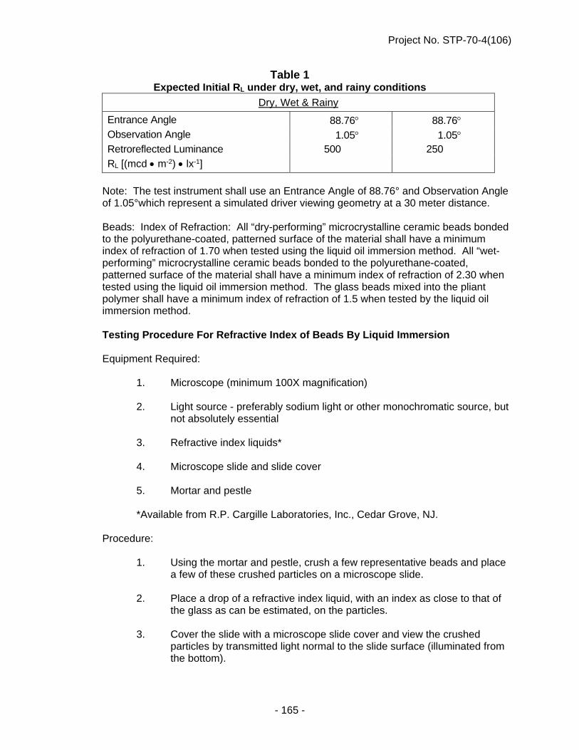
Project No. STP-70-4(106)
- 165 -
Table 1 Expected Initial RL under dry, wet, and rainy conditions
Dry, Wet & Rainy
Entrance Angle 88.76 88.76 Observation Angle 1.05 1.05 Retroreflected Luminance 500 250
RL [(mcd m-2) lx-1]
Note: The test instrument shall use an Entrance Angle of 88.76° and Observation Angle
of 1.05°which represent a simulated driver viewing geometry at a 30 meter distance.
Beads: Index of Refraction: All “dry-performing” microcrystalline ceramic beads bonded to the polyurethane-coated, patterned surface of the material shall have a minimum index of refraction of 1.70 when tested using the liquid oil immersion method. All “wet-performing” microcrystalline ceramic beads bonded to the polyurethane-coated, patterned surface of the material shall have a minimum index of refraction of 2.30 when tested using the liquid oil immersion method. The glass beads mixed into the pliant polymer shall have a minimum index of refraction of 1.5 when tested by the liquid oil immersion method.
Testing Procedure For Refractive Index of Beads By Liquid Immersion
Equipment Required: 1. Microscope (minimum 100X magnification) 2. Light source - preferably sodium light or other monochromatic source, but
not absolutely essential 3. Refractive index liquids* 4. Microscope slide and slide cover 5. Mortar and pestle *Available from R.P. Cargille Laboratories, Inc., Cedar Grove, NJ. Procedure: 1. Using the mortar and pestle, crush a few representative beads and place
a few of these crushed particles on a microscope slide. 2. Place a drop of a refractive index liquid, with an index as close to that of
the glass as can be estimated, on the particles. 3. Cover the slide with a microscope slide cover and view the crushed
particles by transmitted light normal to the slide surface (illuminated from the bottom).

Project No. STP-70-4(106)
- 166 -
4. Adjust the microscope mirror to allow a minimum light intensity for viewing. This is particularly important if sodium light is not used.
5 Bring a relatively flat and transparent particle into focus. 6. By slightly raising and lowering the objective (microscope tube), look for
one or both of the following:
a. Becke Line - This light line will appear to move either into the particle or away from it. In general, if the objective is raised, the line will move toward the material of higher refractive index; if the objective is lowered, the line will move toward the material of lower index.
b. Variation in Particle Brightness - When raising the object from a
sharp focus, the particle will appear to get brighter or darker than the surrounding field. If it becomes brighter, the glass has a higher refractive index than the liquid. If it becomes darker, the glass has a lower refractive index than the liquid. In both cases, the opposite will be true if the object is lowered.
7. This test can be used to confirm that the beads are above or below a
specified index. It can also be used to give an accurate determination of the index (± 0.001). This is done by using several refractive index liquids until a match or near match of indices occurs. The index of the glass will equal that of the liquid when no Becke line and no variation in bead brightness can be observed.
The size and quality of the beads shall be such that the performance requirements for the retroreflective pliant polymer shall be met.
Acid Resistance: The beads shall show resistance to corrosion of their surface after exposure to a 1% solution (by weight) of sulfuric acid. The 1% acid solution shall be made by adding 5.7cc of concentrated acid into 1000cc of distilled water. CAUTION: Always add the concentrated acid into the water, not the reverse. The test shall be performed as follows:
Take a 1-inch x 2-inch sample, adhere it to the bottom of a glass tray and place just enough acid solution to completely immerse the sample. Cover the tray with a piece of glass to prevent evaporation and allow the sample to be exposed for 24 hours under these conditions. Then decant the acid solution (do not rinse, touch or otherwise disturb the bead surfaces) and dry the sample while adhered to the glass tray in a 150° F. (66° C.) oven for approximately 15 minutes.
Microscopic examination (20X) shall show no more than 15% of the beads having a formation of a very distinct opaque white (corroded) layer on their entire surface.
Color: The preformed markings shall consist of white film with pigments selected and blended to conform to standard highway colors.

Project No. STP-70-4(106)
- 167 -
Skid Resistance: The patterned surface of the retroreflective pliant polymer shall provide an initial average skid resistance value upon manufacturing of 45 BPN when tested according to ASTM E303 except values shall be taken in one direction and then at a 45 angle from that direction. These two values shall then be averaged to find the skid resistance of the patterned surface.
Patchability: The pavement marking material shall be capable of use for patching worn areas of the same type in accordance with manufacturer’s instructions.
Thickness: The patterned material without adhesive shall have a minimum caliper of 0.065 inches (1.651mm) at the thickest portion of the patterned cross-section and a minimum caliper of 0.02 inches (.508mm) at the thinnest portion of the cross-section.
VI. Installation The markings shall be applied in accordance with the manufacturer’s installation
instructions. Marking configurations shall be in accordance with the “Manual on Uniform Traffic Control Devices.” Tape shall not be installed unless the surface and air temperatures are in compliance with the manufacturer's specifications. The Contractor shall have on the project at all times during the application of the permanent pavement markings at least one employee with a valid American Traffic Safety Services Association (ATSSA) certification. The ATSSA certification may be for either a "Certified Pavement Marking Technician" or a "Certified Pavement Marking Specialist." The Contractor shall provide the Engineer a copy of the employee's certification prior to the beginning of work.
VII. Observation
Following initial completion of all pavement marking, there will be a 180 day observation period before final acceptance. During the observation period, the Contractor, at no expense to the Department of Roads, shall replace any markings that the Engineer determines are not performing satisfactorily due to defective materials and/or workmanship in manufacture and/or application. At the end of the observation period, the minimum required retention percentage for markings installed shall be 90%. Determination of Percentage Retained - The percentage retained shall be calculated as the nominal area of the strip less the area of loss divided by the nominal area and expressed as a percentage of the nominal area. A claim, made by the State against the Contractor, shall be submitted to the Contractor in writing within 30 days after the 180-day observation period. When such a claim is made prior to August 1, the replacement material shall be installed during that same construction season. Replacement material for any claim after August 1, shall be installed prior to June 1, of the following year. Marking replacement shall be performed in accordance with requirement specified herein for the initial application, including but not limited to surface cleaning, sealer application, etc.
.065 in. .020 in.
Project No. STP-70-4(106)
- 168 -
Final acceptance of all marking will include an inspection of the appearance of the markings during daylight and darkness. Any markings that fail to have a satisfactory appearance during either period, as determined by the Engineer, shall be reapplied at no expense to the Department of Roads. Final acceptance of the pavement marking will be: (1) 180 days after the initial completion of all work, or (2) upon completion of all corrective work, whichever occurs last.
VIII. Contract Units and Basis for Payment Subsection 423.04 of the 2007 Standard Specifications is amended to include the item:
“_____ Wet Reflective Preformed Pavement Marking, Type 4, Grooved”. The price shall be full compensation for grooving the pavement surface, furnishing and installing all markings, and for all materials (including adhesive), labor, tools, equipment and incidentals necessary to complete the work.
Payment will be made under:
Pay Item Pay Unit _____ Wet Reflective Preformed Pavement Marking, Linear Foot Type 4, Grooved
TEMPORARY TRAFFIC CONTROL FOR PERMANENT PAVEMENT MARKING (D-13-1007)
Paragraph 4. of Subsection 423.04 in the Standard Specifications is void.
TRAFFIC CONTROL MANAGEMENT Description and General Requirements Paragraph 1. of Subsection 422.01 in the Standard Specifications is void and superseded by the following: 1. a. This work consists of furnishing, installing at the locations shown on the plans,
operating, maintaining, and when work is complete, removing the temporary traffic control devices described in this Section. This work shall also consist of providing Traffic Control Management by furnishing one or more qualified individuals who shall be specifically responsible for performing or supervising the installation, inspection, maintenance, and removal of those devices.
b. When project conditions warrant, the Engineer may suspend the need for Traffic
Control Management and will notify the Contractor accordingly. The Contractor shall be given at least three days' notice of the suspension, but the work may be suspended in a lesser time if mutually acceptable to the Department and the Contractor. During periods when no payment is being made for Traffic Control Management under this special provision, this provision will not apply.
Project No. STP-70-4(106)
- 169 -
Paragraphs 2.i., 2.j.(2)(ii), and 2.k. of Subsection 422.01 of the Standard Specifications are void. Paragraph 2. of Subsection 422.01 of the Standard Specifications is amended to include the following: p.(1) The Contractor shall designate an individual, other than the Project
Superintendent, to be the Traffic Control Manager for the project. This person shall be qualified by having attended and having satisfactorily passed the examination which accompanies the training for the courses for Traffic Control Supervisor or Traffic Control Technician offered by the American Traffic Safety Services Association (ATSSA). The training shall have been completed no more than 4 years prior to working on the project. Formal certification by ATSSA in these disciplines is encouraged, but not mandated. Other training or certifications may be accepted if approved by the Engineer. The Traffic Control Manager shall also possess a current Flagger Certification Card. Documentation of the Traffic Control Manager's training or certifications shall be provided to the Engineer prior to the installation of any traffic control devices on the project.
(2) The Contractor may also designate one or more Assistant Traffic Control
Managers for the project. These individuals shall possess a valid Flagger Certification Card and be qualified by having attended and having satisfactorily passed the examination which accompanies the training for the course for Traffic Control Technician or Traffic Control Supervisor offered by the American Traffic Safety Services Association (ATSSA) --- the training having been completed no more than 4 years prior to working on the project --- or by certification according to the Department’s certification program for Assistant Traffic Control Managers --- the training having been completed no more than 2 years prior to working on the project . Documentation of the Assistant Traffic Control Manager's training or certifications shall be provided to the Engineer.
(3) In order to be qualified according to the Department’s Certification Program, the
prospective Assistant Traffic Control Manager must: i. View the 47-minute video “Training and Certification of Assistant Traffic
Control Managers.” ii. Correctly answer 80 percent of the questions on an examination that
accompanies the video. (4) Upon satisfactory completion of the training and examination procedure, the
prospective Assistant Traffic Control Manager shall be issued an Assistant Traffic Control Manager Certification Card by the examining Contractor. The Assistant Traffic Control Manager’s name, last four digits of social security number, and test score shall be reported to the Construction Engineer on DR Form 90a, “Certification Report for Assistant Traffic Control Managers.”
(5) The video examination forms, Assistant Traffic Control Manager Cards, and
Certification Reports for Assistant Traffic Control Managers shall be furnished by the Department.

Project No. STP-70-4(106)
- 170 -
q. The Traffic Control Manager or Assistant Traffic Control Manager shall be available and reasonably accessible (within 30 minutes) to the project during normal working hours on every day that work is being performed on the project and always on-call at other times. During other than normal working hours, these individuals shall respond and be on the project within 60 minutes of notice being given that traffic control items on the project are in need of attention. The Contractor may elect to have an employee or employees perform this function simultaneously on more than one project, but shall not be relieved from the sanctions or disincentives that may be imposed for failure to meet the deadlines specified herein.
r. The Traffic Control Manager's or Assistant Traffic Control Manager's activities on
the project shall be dedicated to the purpose of monitoring and maintaining the traffic control devices. The performance of other crafts or trades will be permitted, but shall be secondary to the performance of duties associated with traffic control.
s. The Contractor shall provide prior to the installation of any traffic control devices
on the project two to four telephone numbers where the Traffic Control Manager or an Assistant Traffic Control Manager may be reached 24 hours a day, seven days a week.
t. The Traffic Control Manager or Assistant Traffic Control Manager shall have
available at all times an approved, current version of the Traffic Control Plan. u. If corrective action is not taken by the Contractor within the times specified in
Paragraph 2.q., the Engineer may suspend all work on the project until the problem is corrected. The Engineer shall make reasonable allowance for existing weather conditions in the case of materials whose installation is governed by temperature or other atmospheric conditions.
Construction Methods Subsection 422.03 of the Standard Specifications is amended to include the following: 20. The Traffic Control Manager's or Assistant Traffic Control Manager's duties shall
include: a. Insuring that all traffic control devices, including flagging operations, are
functioning properly, are clean, and are correctly located as shown on the Traffic Control Plan or as directed by the Engineer. This provision in no way restricts the cleaning, repair and maintenance of traffic control devices to the Traffic Control Manager or his or her assistants.
b. Inspecting all traffic control devices on every calendar day that traffic
control devices are in place, whether in use or covered. Inspections shall take place a minimum of twice daily, at least two inspections shall be eight hours apart, and at least one weekly inspection shall be during the hours of darkness. However, during or following periods of inclement weather or when the situation warrants for other reasons, inspections shall be done more frequently. Additionally, when flagger control is being utilized, at least one inspection each week shall be performed during

Project No. STP-70-4(106)
- 171 -
flagging operations for monitoring purposes. The Traffic Control Manager or Assistant Traffic Control Manager shall perform the inspections.
c. Monitoring the cleaning and maintenance of all traffic control devices and
the placement of temporary pavement markings. d. Completing a Traffic Control Inspection Form provided by the Engineer at
the completion of each inspection. These forms shall be submitted daily to the Engineer, either in person or via facsimile transmission.
e. Monitoring flagging operations on the project to insure signing and
flagging techniques are in compliance with Department and ATSSA requirements (flagger location and proper spacing / signage as per the plans). The Traffic Control Manager or Assistant Traffic Control Manager shall not act as a flagger, except in an emergency or when providing relief for short periods of time.
f. Coordinating all traffic control operations, including those of
subcontractors and suppliers. g. Coordinating traffic-related activities with the appropriate law
enforcement, fire, and emergency medical agencies. h. Attending all project scheduling meetings. Method of Measurement Subsection 422.04 of the Standard Specifications is amended to include the following: 21.(1) Traffic Control Management is measured by the day for the actual number of
days management and inspection are required and provided. Payment will only be made for one day of Traffic Control Management during each midnight-to-midnight period regardless of the number of Traffic Control Managers or Assistants required to adequately perform the work.
(2) No measurement will be made when the Engineer has suspended the need for
Traffic Control Management and notified the Contractor accordingly. Basis of Payment Paragraph 1. of Subsection 422.05 of the Standard Specifications is amended to include the following:
Pay Item Pay Unit Traffic Control Management Day (d)
Paragraph 15. of Subsection 422.05 of the Standard Specifications is renumbered to be Paragraph 16. Subsection 422.05 of the Standard Specifications is amended to include the following: 15. With regard to inspection, maintenance and repair of temporary traffic control
devices, an assessment in the amount of $500 per occurrence per day shall be

Project No. STP-70-4(106)
- 172 -
charged to the Contractor when any of the following occur (these assessments shall be in addition to any other liquidated damages which may be assessed):
a. The Contractor fails to respond within the timeframe specified in
Paragraph 2.q. of the amended Subsection 422.01 of the Standard Specifications. Response time shall begin when:
1) The Engineer notifies the Contractor of deficiencies in person;
2) The Engineer makes notification of deficiencies via the 24-hour phone number(s) provided by the Contractor; or
3) The Engineer leaves a message or receives no answer at the number(s) provided;
b. The Contractor fails to begin corrective actions to repair, replace, remove,
relocate, or clean any traffic control devices or pavement markings within two hours of the completion of an inspection that uncovers deficiencies or within two hours of notification of deficiencies by the Engineer (including flagging operations).
c. The Contractor fails to begin corrective actions to repair, replace, remove,
relocate, or clean any traffic control devices or pavement markings within two hours of documented notification by an official law enforcement agency (including flagging operations).
d. The Contractor fails to correct improper flagging procedures. e. The Contractor fails to make or report the inspections prescribed in this
specification. f. The Engineer observes and documents any occurrence of the Contractor
or his or her subcontractors flagrantly disregarding the necessary maintenance of traffic control devices that are in obvious need of attention.
CONCRETE PROTECTION BARRIERS (D-20-0916)
Guidance for concrete protection barriers:
1. Type A: 4-loop barriers with a large opening at the bottom. Type B: 6-loop barriers with 4 lifting slots and no slots for tie-down rods. Type C: 6-loop barriers with 4 lifting slots and 6 slots for tie-down rods. 2. Type A barriers will not be allowed for use on NDOR projects whose contract
start date is January 1, 2018 or later, regardless of requested or granted early starts that begin projects prior to that date. Type A barriers will not be allowed on interstate or freeway roadways.

Project No. STP-70-4(106)
- 173 -
3. Barriers Type B and C may be used on this project and may directly be pinned to each other in the same installation arrangement.
4. Other existing barriers meeting NCHRP 350 or MASH (Test Level 3) testing
guidelines and FHWA approval may only be used with written permission (containing this project name and/or control number) from the District and Roadway Design Division.
5. If new barriers are to be fabricated for use on this project, only Type C barriers
shall be fabricated. Paragraph 5 of Subsection 422.03 in the Standard Specifications is amended to include the following: f. (1) Concrete protection barriers that become dislodged or moved out of alignment
shall be placed back in alignment as soon as practical. If the dislodged barriers are considered to be a hazard to the traveling public by the Engineer, or the barriers encroach into the traveled lane, the barriers shall be realigned within four (4) hours of the time the Contractor is notified. For each occurrence, failure to realign the barriers within the four (4) hour time period will result in the assessment of a lump sum $1,000 liquidated damage assessment and the Engineer may proceed to correct the adverse condition(s) in a manner that is deemed appropriate. The Contractor will also be assessed the cost incurred when the action is performed by others. This assessment has not been provided for elsewhere in the contract and shall be considered in addition to other liquidated damage assessments which are a part of the contract.
POLES AND TOWERS (D-23-0416)
Paragraph 1.a.(1) of Subsection 408.01 in the Standard Specifications is void and superseded by the following:
(1) The Contractor shall furnish and install poles and towers of the size and type shown in the plans. Each traffic signal pole, lighting pole and tower, complete with all of its components, shall be designed in accordance with AASHTO Standard Specifications for Structural Supports for Highway Signs, Luminaires, and Traffic Signals (Sixth Edition 2013, including all current Interim Revisions).
LUMINAIRE REQUIREMENTS (LIGHTING UNITS 1 THRU 12)
Paragraph 2. of Subsection 415.02 in the Standard Specifications is void and superseded by the following: 2. Lamps provided shall be as shown in the plans.

Project No. STP-70-4(106)
- 174 -
Paragraph 7. of Subsection 1073.02 in the Standard Specifications is amended to include the following: 1. Conventional Roadway Luminaires A. Housing Luminaire housing shall be "cobra-head" style, of pressure die-cast
aluminum, Large Housing Series. The casting shall be sound, complete, with smooth edges and free of flash. The lower portion of the housing shall be hinged for easy access.
The optical compartment shall be effectively sealed and filtered using a
dacron polyester filter. The seal/filter combination shall be provided between the reflector and lens and between the socket assembly and reflector. The seal/filter combination shall be under compression when the assembly is in operating position. Seal/filter combination shall be of heat resisting material selected to last the functional life of the unit, but shall be easily replaceable should they become damaged. The optical compartment door shall be secured in position with a positive latch mechanism. The hinge arrangement shall be designed to prevent accidental disengagement when it is in the open position.
Finish shall be a gray Polyester Powder Coat or an electrodeposited
epoxidized acrylic paint coat capable of successfully withstanding 1,000 hours of salt spray test per ASTM B 117.
Attachment hardware used to secure components to the aluminum
housing shall be organically coated. Stainless steel or galvanized hardware is not allowed.
Housing must be legibly and durably marked with the lamp size, using
ANSI NEMA lamp identification label. Luminaire must be UL listed as suitable for wet locations. B. Slipfitter The slipfitter shall accept 1 1/4 inch to 2 inch (32 mm to 50 mm) pipe. C. Reflector The reflector shall be hydroformed aluminum with an approved aluminum
oxide or silica coating bonded to the inside and outside surfaces. D. Socket The socket shall be a mogul base porcelain.

Project No. STP-70-4(106)
- 175 -
E. Lens The lens shall be made of clear tempered flat glass, heat resistant and
free from imperfections. F. Terminal Block A terminal block will be required. G. Ballast The ballast shall be of the (CWA) Auto Regulator lead type for the high
pressure sodium lamp size as indicated in the plans. Ballast shall be dual volt 120/240 or multi tap, ballast to be factory wired
to 240 volt. The ballast and starting aid shall not incur significant life reduction should
the lamp continue in open or shorted circuit condition for a six-month period.
Regulation and Operation: At nominal line voltage and nominal lamp voltage, the ballast design center will
not vary more than 5% from rated lamp wattage. Lamp wattage variation shall not exceed 10% for a ±10% line voltage variation.
The ballast/lamp combination must provide reliable starting to -40 degrees F
(-40 degrees C). Ballast starting current must not exceed normal operating current. Power factor must range between 65% and 90% through all operational modes. H. Photometric and Performance Requirement The luminaire shall have "cutoff" control characteristics as follows:
Candela per 1000 lumens shall not exceed 100 (10%) at a vertical angle of 80 degrees above nadir, and 25 (2.5%) at an angle of 90 degrees above nadir horizontal.
The luminaries, with lamp size and lumens as specified in the plans and
installed in accordance with the following parameters, shall provide an average maintained horizontal illumination level of 1.0 FC with an average to minimum uniformity ratio not exceeding 3.5:1. The maximum to minimum uniformity ratio shall not exceed 7.0:1. Any adjustments to the luminaire’s optical system needed to provide a light distribution meeting the preceding requirements shall be made at the factory prior to shipment.

Project No. STP-70-4(106)
- 176 -
Parameters used; roadway width 28’, median width n/a, pole spacing 200, mounting height 40, pole setback 15, mastarm length 12, maintenance factor .81, pole layout staggered.
I. Substitutions and Variations No substitutions or variations of the above will be allowed. J. Approval Requirements In addition to the requirements for approval of the roadway lighting
luminaires as outlined in Subsection 1073.02, the Contractor may be asked to supply electric files of IES formatted photometrics for each type of luminaire he/she proposes to furnish for the project. The electronic files must be compatible with the NDOR Operating System.
The Contractor shall be prepared, upon request, to furnish a working
sample of any luminaire proposed for this project (sample will be returned to the Contractor or counted as part of the contract quantity).
The right is reserved to reject any and all proposals. The State of
Nebraska will decide all questions which may arise as to the quality or acceptability of the luminaire submitted for approval under this specification.
Manufacturers allowed to submit luminaires for approval are as follows:
Cooper General Electric
Hubbell American Electric
LED ROADWAY LUMINAIRES (LIGHTING UNITS 13 THRU 16)
Paragraph 7. titled “Roadway Lighting Luminaires” of Subsection 1073.02 in the Standard Specifications is amended to include the following: Scope: The roadway luminaires for lighting units 13 thru 16 shall be of the traditional cobra head design in order to match the HPS cobra head luminaires existing along the park access road. Each of the four new luminaires shall consist of an assembly that utilizes light emitting diodes as its light source. The four new LED luminaires shall be designed for applications that require a pole/mast arm mounted light fixture with long life and low maintenance. The complete LED luminaire shall consist of a housing, LED array, terminal block, surge protector, electronic driver (power supply), electronic photo control receptacle with shorting cap and shall be fully pre-wired and ready for installation. The LED luminaire and its components shall conform to the following requirements:

Project No. STP-70-4(106)
- 177 -
A. GENERAL REQUIREMENTS AND INFORMATION: 1. Roadway lighting systems on all NDOR projects using LED luminaires shall be
designed to conform to the requirements of IESNA Standard RP-8, latest version. The illumination method of lighting design in foot candles shall be used and its recommended values shall govern. The Project Site Parameters: (lane width, road surface classification, luminaire mounting height, pole mast arm length, pole setback, pole layout, etc.), the LED Luminaire Criteria: (luminaire wattage, input voltage, BUG rating, photometric requirements, etc.) and the Required Photometric Performance Criteria: (average maintained horizontal illumination, ave/min and max/min uniformity ratios) shall be as shown on the lighting plans and/or as listed in Appendix “A” of these Lighting Special Provisions.
2. Laboratories performing tests and compiling data on LED luminaires in
compliance with this specification must be (NRTL), (NVLAP), (ULDAP) or (CALiPER) accredited.
3. All LED luminaires shall be provided with a NEMA 3 prong, twist-lock,
non-dimming ANSI C 136.10 compliant photocontrol receptacle with electronic photocontrol or shorting cap. Luminaires whose circuit is controlled by a relay at the lighting control center and have no need for an electronic photocontrol shall be provided with a rain tight shorting cap. A photocontrol receptacle with dimming contacts may be supplied as an option to the non-dimming photocontrol receptacle.
4. The optical assembly of the luminaire shall be protected against dust and
moisture intrusion with a minimum Ingress Protection rating of IP66 in accordance with ANSI Standard C136.25.
5. LED luminaires shall provide sufficient lumen output to meet the lighting criteria
as specified in the project plans and project Special Provisions. 6. LED luminaires shall have a nominal Correlated Color Temperature (CCT) of
4000 ± 300 degrees Kelvin and a minimum Color Rendering Index (CRI) of 70. 7. LED luminaires shall comply with the Class “A” electronic noise emission limits
as outlined in Title 47, Subpart B, Section 15 of the FCC regulations. 8. The maximum weight of the luminaire shall be 35 lbs. The maximum projected
area of the luminaire shall be 1.2 sq. ft. 9. The LED luminaire and all of its components shall be lead free and ROHS
compliant. 10. Each LED luminaire shall be listed with Underwriters Laboratory Inc. as being in
compliance with UL-1598 and suitable for use in wet locations. 11. Each type of LED luminaire proposed for use on a State project shall be tested
as a complete unit in accordance with IESNA Standard LM-79; shall have the lumen depreciation of its LED light source(s) measured in accordance with IESNA Standard LM-80; shall have its In Situ LED and power supply temperature tests taken in accordance with ANSI/UL Standard 1598 and shall have its lumen

Project No. STP-70-4(106)
- 178 -
maintenance (useful life) calculated and documented in accordance with IESNA Technical memorandum TM-21 and its addenda. All testing must be performed by a Nationally Recognized accredited testing laboratory with the most current version of the testing standard being followed.
12. LED luminaires shall be latched and hinged in a manner that will allow tool less
entry to the Luminaires Internal components. The luminaires internal LED light engine, surge protection device and LED driver shall each be field repairable or replaceable.
13. LED luminaires shall be capable of slip-fitter mounting to a 2-3/8” O.D. pipe mast
arm with a plus or minus five degree leveling adjustment at 2.5 degree increments. The bolts and slip-fitter shall be of corrosion resistant material compatible with the luminaire and mast arm or treated to prevent galvanic reaction. Luminaires shall be compliant with ANSI C136.31 vibration level 2 for both bridge and overpass applications (3G rating).
14. The luminaire refractor (lens) shall be manufactured of precision engineered,
UV stabilized, high impact, scratch resistant, acrylic or polycarbonate plastic or heat and impact resistant glass.
B. HOUSING REQUIREMENTS: 1. The luminaire housing shall be “cobra-head” style of 96% copper free die-cast
aluminum. The cast housing shall be sound, complete, with smooth edges and free of flash. The housing hardware shall be of stainless steel or zinc plated steel with a chromate top coat.
2. The luminaire housing shall have a grey or silver polyester power-coat finish
capable of successfully withstanding 1,000 hours of salt spray testing per ASTM B 117 while exhibiting no greater than 30% reduction in gloss per ASTM D 523.
3. Management of the heat generated by the LED light source(s) shall be by heat
sink elements (fins) protruding from the luminaire housing. The heat sink elements shall be designed to be self-cleaning when rained upon and to resist debris accumulation. The use of fans, pumps or other mechanical devices to dissipate heat will not be allowed.
4. The luminaire housing must be externally labeled per ANSI C136.15 and
internally labeled per ANSI C136.22. C. ELECTRICAL REQUIREMENTS: 1. LED luminaires under this specification shall be capable of operating on single
phase, 60 Hz, 120 and 240 volt alternating current and shall be unaffected by input voltage fluctuations of plus or minus ten percent.
2. Each luminaire shall be provided with a 10Kv (min)/5Ka (min) replaceable surge
protection device (SPD) meeting UL 1449 high exposure requirements. The SPD shall be field replaceable and shall have a failure mode such that the luminaire will no longer operate if the SPD fails.

Project No. STP-70-4(106)
- 179 -
3. Provide each LED luminaire with a replaceable driver that is internal to the
luminaire and thermally separate from other internal components. The driver shall operate at the line voltage shown in the plans; shall have a power factor of 0.90 or greater; shall comply with ANSI/UL Standard 1012 and be able to tolerate sustained open circuit and short circuit output conditions without damage. The driver shall have a minimum rated life of 100,000 hours at 25° C (77° F) ambient and shall comply with the latest FCC Class “A” electronic noise emission limits.
D. PHOTOMETRIC AND PERFORMANCE REQUIREMENTS: 1. Luminaires shall have the optical assembly necessary to provide the IESNA Light
Distribution type and light level as required by the project specifications. The luminaire optical assembly shall have a minimum efficiency of 85% regardless of the distribution type The luminaire light distribution pattern on the roadway shall have an evenly dispersed appearance. All LED sources within the luminaire shall provide the same optical pattern such that a catastrophic failure of an individual LED source will not constitute a loss in the luminaire distribution pattern.
2. Luminaires shall have an IESNA TM-15 Backlight, Up-light and Glare (BUG)
rating as called for in the lighting plans or in Appendix “A” of these lighting special provisions.
3. All luminaires shall be fully operational in an ambient temperature range of -40° C
(-40° F) to 40° C (104° F). 4. All LED luminaires shall maintain a minimum of 70% of their initial lumen output
(L70) after 70,000 hours of operation (19 yrs @ 10 hrs/day) at 25°C (77°F). This projection of lumen maintenance shall be based on recommendations provided by IESNA technical memorandum TM-21 and data collected according to the latest issue of IESNA standard LM-80.
5. LED luminaires shall have a minimum luminaire efficacy of 70 lumens per watt
when tested in accordance with IESNA standard LM-79. 6. The LED luminaires average maintained illumination level shall be determined by
applying lighting support software utilizing a Light Loss Factor (LLF) defined as follows:
Light Loss Factor (LLF) = Lamp Lumen Depreciation (LLD) x Lumen Dirt
Depreciation (LDD) where (LLD) = the percentage of LED lumen maintenance obtained from the
luminaire manufacturer’s TM-21 report at 70,000 hours and an ambient temperature of 25° C (77° F).
(LDD) = 0.90

Project No. STP-70-4(106)
- 180 -
E. APPROVAL AND ACCEPTANCE REQUIREMENTS: 1. Only LED luminaires, tested, approved and certified to by a Nationally
Recognized Testing Laboratory (NRTL) or a laboratory accredited under the (NVLAP), (ULDAP) or (CALIPER) programs will be purchased by the NDOR or allowed to be installed on NDOR projects.
2. In addition to the requirements for approval of LED roadway luminaires as
outlined in this specification, the Contractor may also be asked to supply electronic IES formatted photometric files for each type of luminaire he/she proposes to furnish to the project. The electronic file must be compatible with the present NDOR operating system.
3. The Contractor shall, in all cases, furnish documentation as outlined elsewhere in
this specification under the title “Required Submittals.” 4. All LED luminaires furnished to a State of Nebraska project must be of one
manufacturer. Proposed luminaire(s) must achieve the photometric levels and uniformity ratios per IESNA LM-79 for the fixture spacing shown in the contract.
5. The Contractor shall be prepared, upon request, to furnish a working sample of
the LED Luminaire proposed for the project. After review and testing, the sample will be returned to the Contractor or counted as part of the contract quantity.
6. The right is reserved to reject any and all proposals. The State of Nebraska will
decide all questions which may arise as to the quality or acceptability of the luminaire(s) submitted for approval under the contract.
F. REQUIRED SUBMITTALS The Contractor shall provide the Nebraska Department of Roads with the following
submittals in electronic format. The electronic submittals shall be sent to the following address: [email protected].
1. Appendix “B” submittal form (attached) as completed by the luminaire
manufacturer. 2. Product cut sheets (shop drawings) of the following: (a) LED luminaire (b) LED light source(s) (c) LED driver (d) Surge protection device 3. IESNA LM-79 luminaire photometric test reports produced by a testing laboratory
with NRTL, NVLAP, ULDAP or CALIPER accreditation. The test report shall contain the:
(a) Name of the testing laboratory (b) Report No. and date (c) Complete luminaire catalog No. (d) TM-15 BUG rating (e) Photometric file in IES format

Project No. STP-70-4(106)
- 181 -
4. Calculations and supporting test data that documents the luminaires lumen maintenance (useful life):
(a) LM-80 data (b) TM-21 calculations (using IESNA LM-80 test data) indicating specific
lumen maintenance life. (c) In-situ temperature measurement test report from an accredited NRTL,
NVLAP, ULDAP or CALIPER Testing Laboratory 5. Instructions for the installation and maintenance of the luminaire 6. Manufacturer’s written warranty G. QUALITY ASSURANCE 1. The LED luminaire manufacturer shall submit a report or certification showing
that an identical sample of each type of LED luminaire furnished to the project under this specification has been tested and certified to by a nationally recognized and accredited testing laboratory.
2. All luminaires shall be of uniform quality and appearance. 3. Each fully assembled luminaire shall be electrically tested for satisfactory
performance prior to shipment from the factory. H. WARRANTY 1. New LED luminaires shall have a minimum ten (10) year manufacturer’s written
warranty on all parts, labor, materials, workmanship, lumen maintenance, LED color and paint finish. Luminaires found non-operable during the warranty time period, shall be repaired or replaced at the manufacturer’s expense. The replacement part(s) or the complete replacement luminaire shall meet all requirements of the original specifications and shall be shipped at manufacturer’s expense to the project location. Lens discoloration and paint finish deterioration such as blistering, cracking, peeling or corrosion shall be considered a failure under the warranty.
2. If more than 10% of a luminaires individual LEDs fail within the warranty period,
the luminaire will be considered defective and must be repaired or replaced. The Department will remove the unit from the field and ship it to the manufacturer for repair or replacement. Return shipment costs shall be the responsibility of the manufacturer.
3. The Contractor shall provide the Project Manager with the luminaire
manufacturer’s written warranty prior to installing the new LED luminaires. 4. The luminaire warranty period shall begin at date of project acceptance.

Project No. STP-70-4(106)
- 182 -
I. BASES OF ACCEPTANCE AND PAYMENT 1. All roadway luminaire manufacturers having a minimum of 5 years’ documented
experience in LED luminaire manufacture and offering a product or products that comply with the project specifications and operational criteria may submit his/her LED luminaires for consideration.
2. An LED luminaire, installed together with a pole, mast arm, break-a-way base
and foundation as a complete lighting unit, will not be paid for as an individual item but will be considered subsidiary to the item “Street Lighting Unit, Type ***” for which payment is being made.
J. REFERENCE DOCUMENTS The latest edition or latest tentative edition of all referenced publications in effect on the
bid advertising date of the project shall apply.

Project No. STP-70-4(106)
- 183 -
APPENDIX “A” NEBRASKA DEPARTMENT OF ROADS
SPECIFICATION FOR LED ROADWAY LUMINAIRES (To be completed by Lighting Designer)
PROJECT SITE PARAMETERS
ROADWAY DATA:
Lane width (ft.) 10 Total number of lanes 2 Median width (ft.) N/A IES Pavement class R1 R2 R3 R4
Posted speed limit < 25 mph > 25 mph
LIGHT POLE DATA
Luminaire mounting height (ft.) 30
Horizontal mastarm length (ft.) 6 Luminaire(s) per pole 1 Pole set-back from edge of travelled way (ft.) 10 Pole set-back from back of curb (ft.) N/A Pole spacing in ft. (same side of roadway) 180 Pole layout One side Opposite Staggered Median
LED LUMINAIRE CRITERIA INPUT POWER: Max. nominal luminaire input power (watts) NOMINAL CCT: Rated correlated color temperature (degrees kelvin) 3500-5000 CRI Min. Color Rendering Index 70 EFFICACY Min. No. lumens per watt 70 BUG RATING: Max. nominal backlight-uplight-glare ratings B3 U0 G3 VOLTAGE: Nominal luminaire input voltage (volts) 240 FINISH: Luminaire housing finish color Gray WEIGHT: Maximum luminaire weight (lbs) 35 EPA: Maximum effective projected area (sq. ft.) 1.2 MOUNTING: Mastarm Post-top Tenon top
VIBRATION: ANSI test level Level 1 (normal) Level 2 (bridge/overpass)
REQUIRED PHOTOMETRIC PERFORMANCE CRITERIA
PHOTOPIC ILLUMINANCE
Maintained illumination level, Fc (min.) 0.70
Avg./min. uniformity ratio (max.) 3.5:1
Max./min. uniformity ratio (max.) 10:1

Project No. STP-70-4(106)
- 184 -
APPENDIX “B” PRODUCT SUBMITTAL FORM
(TO BE COMPLETED BY LUMINAIRE MANUFACTURER)
Luminaire manufacturer
Luminaire designation (1)
Luminaire model number (1)
Housing finish color
Tenon nominal pipe size (inches)
Nominal Luminaire weight (lb)
Nominal Luminaire EPA (ft2)
Nominal input voltage (volts)
ANSI vibration test level Level 1 (Normal) Level 2 (bridge/overpass)
Nominal IES TM-15 BUG ratings B = U = G =
Make/model of LED light source(s)
Make/model of LED driver(s)
Dimmability Dimmable Not Dimmable
Control signal interface
Electrical immunity system failure Possible disconnect No Possible disconnect
Thermal management Moving parts No moving parts
Lumen maintenance testing duration (hours)
Reported lumen maintenance life (hours) (2)
Warranty period (years)
Nominal Value Tolerance (%)
Initial photopic output (lumens)
Maintained light output (lumens)
Lamp Lumen depreciation
Initial input power (watts)
Maintained input power (watts)
Initial LED drive current (mA)
Maintained LED drive current (mA)
Drive current used
CCT (°K)
In-situ LED Tc (°C)
Additional product description (1) Proposed luminaire must meet the requirements as outlined in Appendix “A” of this specification. Attach supporting documentation as required. (2) The reported lumen maintenance life, in hours, shall be no less than that specified in Section D” paragraph 5 of this specification. The number of hours shall not exceed six times the lumen maintenance testing duration shown in the table above and shall be consistent with values submitted for the maintained light output, maintained input power and maintained drive current.

Project No. STP-70-4(106)
- 185 -
SURFACING UNDER GUARDRAIL (E-3-0516)
Amend Section 503 in the Standard Specifications to include Surfacing Under Guardrail. At the Contractor’s option, the surfacing may be constructed using Class “47B-3000” Concrete, Class “BX-3000” Concrete, Class “PR-3000” Concrete (Class 47B-20 Concrete, Class BX-20 Concrete, Class PR-20 Concrete), or any commercially produced hot mix asphaltic concrete, which has been approved by the Engineer. These materials may be used interchangeably during the course of the work except that surfacing at any individual location must be completed with the same material with which the work was begun. If concrete is used in the surfacing, it shall reach a minimum strength of 3000 psi (20 Mpa) before opening to traffic. If asphalt is used in the surfacing, the Contractor shall monitor the density through a combination of rolling pattern and field testing as deemed necessary by the Engineer. The surfacing under guardrail may be placed in a single lift. If placing in multiple lifts, the lower lifts may be placed by means other than a paver, however, the final lift must be placed with a paver. Amend Subsection 302.04 in the Standard Specifications to provide that the work of subgrade preparation for surfacing under guardrail will not be measured for payment, but shall be considered subsidiary to the item “Surfacing Under Guardrail”. Subsection 304.04 in the Standard Specifications is amended to provide that the work of earth shoulder construction associated with surfacing under guardrail will not be measured for payment, but shall be considered subsidiary to the item “Surfacing Under Guardrail.” Subsection 503.05 in the Standard Specifications is amended to provide that P.G. Binder used in the asphaltic concrete will not be measured for payment, but shall be considered subsidiary to the item “Surfacing Under Guardrail”. Subsection 504.04 in the Standard Specifications is amended to provide that the application of a tack coat, including furnishing emulsified asphalt, will not be measured for payment, but shall be considered subsidiary to the item “Surfacing Under Guardrail”. The work and materials required for any drainage curb placed on surfacing under guardrail will not be measured and paid for, but will be considered subsidiary to the item “Surfacing Under Guardrail”. The work and materials required for surfacing under guardrail will be paid for at the contract unit price per square yard (square meter) for the item “Surfacing Under Guardrail”. Payment will be full compensation for the work prescribed in these Special Provisions and the Standard Specifications.

Project No. STP-70-4(106)
- 186 -
COLD WEATHER ASPHALTIC CONCRETE PLACEMENT (E-8-1214)
Table 501.02 in the Standard Specifications is void and superseded by the following:
Table 501.02 Cold Weather Asphaltic Concrete Placement
Lift Thickness Minimum Surface Temperatures* Less than 2 inches (50 mm) 45°F (7°C)
2 to 3 inches (50 mm to 75 mm) 37°F (3°C) Greater than 3 inches (75 mm) 35°F (2°C)
*32°F (0°C) for all lift thicknesses when a Warm Mix Additive is used in accordance with the contract.
ASPHALTIC CONCRETE (E-8-1211)
Paragraph 2.a.5.(ii) of Subsection 503.03 is void and superseded by the following: During storage, the PG Binder temperature shall be maintained in accordance with
binder supplier recommendations. All plants shall be equipped with a circulating system for PG Binder which is designed to assure proper and continuous circulation during the operating period. Storage tanks shall have sufficient capacity to provide for continuous operation. The tanks shall be situated and constructed to allow the volume of the PG Binder to be safely and accurately determined at any time.
Paragraph 2.a. of Subsection 503.04 is void and superseded by the following: 2. Asphalt Mix Control Strip:
a. At the Contractor’s option, the control strip may be waived. The decision to omit the control strip must be communicated to the Engineer prior to the start of production. When the control strip is waived:
(1) The moving average of four air voids values for the first three
asphaltic concrete sublots is not valid and a pay factor of 1.0 shall be applied.
(2) The first three asphaltic concrete sublots shall be subject to the
following removal criteria and removal shall be at no cost to the Department.
Sublot Removal Criteria 1-1 Va1-1 less than 1.5 or greater than 7.0 1-2 (Va1-1 + Va1-2) ÷ 2 less than 1.67 or greater than 6.67 1-3 (Va1-1 + Va1-2 + Va1-3) ÷ 3 less than 1.83 or greater than 6.33
Where: Va1-1 = the single test air voids for Sublot 1-1 Va1-2 = the single test air voids for Sublot 1-2
Va1-3 = the single test air voids for Sublot 1-3

Project No. STP-70-4(106)
- 187 -
b. On the first production day, a 600 ton (544 Mg) control strip shall be placed and approved before full production begins. The Contractor shall construct the control strip using the approved asphalt mix design with laydown and compaction procedures that are representative for the project.
c. The Contractor shall take at least 3 control strip mixture samples and
record the test results for the mixture properties. The Contractor will also record compaction density values and rolling pattern information. This data will be for information only and shared with the Engineer.
Table 503.02 is void and superseded by the following:
Table 503.02
Control Strip Sampling
Sample No. Ton (Mg) Air Voids for SPH Air Voids for SPR
1 0 to 200 (0-180) 2.5 to 6.0 1.5 to 5.0
2 201 to 400 (181-363) 2.5 to 6.0 1.5 to 5.0
3 401 to 600 (364-544) 2.5 to 6.0 1.5 to 5.0
Paragraph 2.b.(2) of Subsection 503.04 is void and superseded by the following:
(2) Marshall or Gyratory air voids of each sample shall be calculated using the maximum specific gravity of that sample.
Paragraph 2.b.(4) of Subsection 503.04 is void and superseded by the following: The control strip will be accepted at 100% pay if all of the following test results are met.
If any of the following test results are not met, the control strip will be subject to removal.
(i) The Dust to Binder ratio is between 0.70 and 1.70.
(ii) CAA is no more than 5% lower than the minimum specified shown on Table 1028.02 using blended cold feed material or ignition oven test results. FAA is no more than 0.5% lower than the minimum specified using blended cold feed material or no more than 1.0% lower than the minimum specified using ignition oven test results shown on Table 1028.03.
(iii) Air voids are between 2.5% to 6.0% for SPH and between 1.5% to 5.0%
for SPR. Paragraph 2.h. of Subsection 503.04 is void. Paragraph 2.j. of Subsection 503.04 is void and superseded by the following:
j. When a control strip is constructed, the Contractor will use the three individual air void tests within the control strip and apply those individual values to the individual air void test result of the first 750 ton (680 Mg) sublot of Lot 1 to

Project No. STP-70-4(106)
- 188 -
calculate the initial moving average of four and resulting pay factor for the initial 750 ton (680 Mg) sublot.
Paragraphs 5.a.(1) and 5.a.(3) of Subsection 503.04 are void and superseded by the following:
a. (1) The actual mixing temperature shall be selected by the Contractor, in accordance with binder supplier recommendations, to provide adequate aggregate coating and mixture compaction at laydown.
a. (3) Never shall the selection of the mixing temperature be such that drainage of the
PG Binder from the aggregate will exceed contract specifications. Paragraphs 10.a. and 10.b. of Subsection 503.04 are void. Paragraphs 2.a. and 2.b.(1) of Subsection 503.06 are void. Paragraph 2.b. (2) of Subsection 503.06 is void and superseded by the following;
(2) For each sublot of Asphaltic Concrete Type SPR, SPS and SPH, the asphaltic concrete unit price is a product of all applicable pay factors for the item "Asphaltic Concrete, Type _____”. Included in a sublot, following approval of the control strip(s), may be any roadway Asphaltic Concrete Type SPR, SPS and SPH which is produced, sampled and tested and approved by the Engineer for use as Patching, State Maintenance Patching, and Asphalt for Intersections and Driveways on project shall be eligible for inclusion in sublot(s) tonnage pay factor determination using the roadway Asphaltic Concrete Type _______ unit price. When a control strip is not constructed, the pay factor for the running average of four air voids shall be fixed at 1.0 for the first three asphaltic concrete sublots.
Paragraphs 5.a., 5.b., and 5.c. of Subsection 503.06 are void and superseded by the following:
5. a. When asphaltic concrete in any lot 3750 tons (3400 Mg) or portion of a lot 3750 tons (3400 Mg) is rejected and removed from the road, payment will not be made for the asphaltic concrete or for the PG Binder contained in the rejected material. The determination of the quantity of PG Binder for which payment will not be made will be based on the percent of PG Binder used in the rejected material.
b. The order of precedence to determine the PG Binder quantity is:
(1) Actual lot 3750 tons (3400 Mg) tests.
(2) The average of the day’s run.
(3) The job-mix formula.
Paragraph 12. of Subsection 503.06 void.

Project No. STP-70-4(106)
- 189 -
TACK COAT (E-8-1214)
Subsection 504.02 in the Standard Specifications is amended to include the following:
Table 504.01
CFS-1, FS-1 Emulsified Asphalt Requirements
Tests on emulsion: Specification
Viscosity, Saybolt Furol, T 59, 25oC (77oF), sec. 20 – 100
Sieve Test, % Retained, maximum (note 1) 0.10
Residue by Distillation, %, minimum 57.0
Storage Stability, %, maximum (note 1) 1.0
Tests on distillation residue:
Penetration, dmm. 40 - 175
Ductility, 25oC (77oF), cm., minimum 40
Solubility in Trichloroethylene, %, minimum 97.5
Note 1: See note “b” of AASHTO M 208
Shall be formulated as either a cationic or anionic, fast-setting emulsion that is suitable for tack coat dilution, and to have an accelerated breaking time in cooler temperature applications.
Subsection 504.03, Paragraph 3.b. is void and superseded by the following:
b. Emulsified asphalt shall be diluted in the distributor with potable water at a rate of one part water to one part emulsified asphalt.
Subsection 504.03, Paragraph 3.c. is void and superseded by the following:
c. The rate of application shall be adequate to bond the new bituminous layer to the existing surface. This shall be from 0.10 to 0.20 Gal/SY (0.45 to 0.90 L/m2) when applied to existing or milled surfaces, and from 0.05 to 0.10 Gal/SY (0.23 to 0.45 L/m2) when applied to freshly laid asphaltic concrete.
Paragraph 2. of Subsection 504.05 is void and superseded by the following:
2. Any amount of tack coat emulsified asphalt which is outside the specified property ranges of Table 504.02, shall be paid for at the contract unit price multiplied by the pay factor determined in Table 504.02. If the resultant Pay Factor for the material indicates rejection as an option, the Engineer will determine if the non-compliant material will be removed.

Project No. STP-70-4(106)
- 190 -
Table 504.02 Tolerances and Pay Factors
Specified Property Tolerance Pay Factor
AASHTO T 59, Prior to Dilution, Residue after Distillation
≥ 56.0% 1.00
54.0% - 55.9% 0.85
52.0% - 53.9% 0.70
< 52.0% 0.40 or Reject
Pay Factors for Tests for ALL other Properties Specified*
1.00 for deviation of ± less than or equal to 10% 0.75 for a deviation of ± greater than 10% to less than or equal to 25%
0.40 or Reject for deviation of ± greater than 25%
* When the specification requirement is stated as a percentage, the test result deviation from the specification will be divided by the specification
value. The resulting deviation percentage is then applied to the listed criteria.
Note: When more than one specified property exceeds specification tolerances, the single largest Pay Factor Reduction will be the one applied.
Paragraph 3. of Subsection 504.05 is void and superseded by the following:
3. When disputes arise in test results, the Department will select an independent laboratory for referee testing on the remainder of the sample. The identity of the independent laboratory will not be revealed until the selected laboratory has completed the referee testing.
a. Only the Contractor can initiate dispute resolution, and request referee
testing.
b. If the independent lab’s tests indicate failing results and pay deductions equal to or greater than the Department’s, the Contractor will reimburse the Department for the cost of testing. If the independent lab’s tests indicate that the material meets specifications or is at a pay deduction less than the Department’s, the Department will assume the cost of testing. When the independent lab’s tests indicate a pay deduction, the lesser of the Department’s and the independent lab’s deductions will be applied.
Paragraph 4. of Subsection 504.05 is void and superseded by the following:
4. Water used to dilute emulsified asphalt is subsidiary to “Tack Coat” and is included in the solution that is placed and measured for payment.
Subsection 504.05 is amended to include the following: 5. Payment is full compensation for all work prescribed in this Section.

Project No. STP-70-4(106)
- 191 -
BITUMINOUS PAVEMENT PATCHING
(E-8-1212) Paragraphs 1, 2 and 3 of Subsection 516.05 in the Standard Specifications are void and superseded by the following: 1. a. Bituminous Pavement Patching of flexible pavement and the repair or
replacement of any subgrade material authorized by the Engineer will be measured by one of the methods described in Paragraph 1.b. based upon the depth of the patch.
b.(1) For patches 16-inches (40cm) deep or less, determined at the time of patching,
the patching will be measured by the ton (megagram) of “Asphaltic Concrete for Patching, Type ___” required to complete the patch and repair any faulty subgrade. No equipment rental will be paid for this work, and all equipment used to complete the work shall be subsidiary to the item, “Asphaltic Concrete for Patching, Type ___.”
(2) For patches more than 16 inches (40cm) deep, determined at the time of
patching, the patching will be measured by the ton (megagram) of “Asphaltic Concrete for Patching, Type ___” required to complete the patch and repair any faulty subgrade. Additionally, the hours of equipment rental required to complete the patching and repair in that portion of the patch deeper than 16-inches will be measured by the hour of equipment rental in accordance with Section 919. Only approved equipment needed to patch and excavate the failure is to be rented, and only the time utilized to perform the work in the region deeper than 16-inches (40 cm) is to be measured. Excluded is any equipment needed to haul asphalt to the site.
2. a. Bituminous Pavement Patching of concrete pavement and the repair or
replacement of any subgrade material authorized by the Engineer will be measured by the square yard (square meter) of completed and accepted work regardless of depth. Additionally, the asphaltic concrete used to complete the patch will be measured for payment and included with the roadway tonnage.
b. Bituminous Pavement Patching of concrete pavement is divided into 3 types (see
Table 516.02). The types are based on the size of the individual patches constructed in a single lane. If a damaged area spans 2 or more lanes, then the continuous patch will be counted as multiple patches -- 1 patch per lane.
Table 516.02 Asphalt Patch Sizes in Rigid Pavement
Type Size A 5 SY (5 m2) or less B Greater than 5 SY to 15 SY (5 m2 to 12.5 m2) C Greater than 15 SY (12.5 m2)

Project No. STP-70-4(106)
- 192 -
3. “Asphaltic Concrete, Type ____,” “Asphaltic Concrete for Patching, Type ___,” “Asphalt Cement ____,” and “Hydrated Lime for Asphalt Mixtures” used in either the patching of flexible pavement or concrete pavement will be measured for payment by the ton (megagram) in accordance with Subsection 503.05.
DROP-OFF/COLD-MILLED TAPERED EDGE (E-8-0515)
Paragraph 7. of Subsection 107.07 is void and superseded by the following. 7. a. The Contractor shall conduct all operations to minimize any drop-offs (abrupt changes in
roadway elevation) exposed to traffic. b.(1) Unless otherwise specified in the Contract, drop-offs greater than 2 inches tall at the
shoulder edge that are adjacent to the traveled way shall be protected by a wedge of compacted stable material capable of carrying traffic (the wedge being 1 vertical to 3 horizontal or flatter). An edgeline warning stripe shall be placed on the traffic side of the drop-off.
(2) The Engineer shall authorize other methods, such as concrete barriers or Type II
barricades, to protect drop-offs when conditions do not allow a wedge of compacted, stable material.
(3) Unless otherwise ordered by the Engineer, drop-offs up to 2 inches (50 mm) may remain
exposed with appropriate warning signs alerting motorists to the condition. c. Open trenches which span all or part of the traveled way and/or auxiliary lanes shall be
no wider than 18 inches (450 mm) and must have a steel-plate cover placed and anchored over them. The plate shall have sufficient strength so as to only allow a maximum vertical deflection of 1/2 inch (12.5 mm). A wedge of suitable material shall create a smooth transition between the pavement and the steel plate. Warning signs shall be used to alert motorists to the presence of the steel plates.
Paragraphs 3.b. and 3.c. of Subsection 510.04 are void and superseded by the following. 3. b. The Contractor shall not leave a milled vertical edge greater than 1-inch tall between
lanes overnight. One of the following options shall be performed if the milling will result in a vertical grade separation greater than 1 inch (25 mm) between lanes:
(1) Milling shall be performed in all adjacent traffic lanes on the same day so that at the end
of each day, no drop off of over 1 inch (25 mm) remains. (2) The milling shall create a tapered edge between the traffic lanes. The tapered edge
shall have a slope from 3 [H]: 1 [V] to 4 [H]: 1 [V], not measured more than one foot in width nor extend into the lane more than one foot. Temporary pavement marking shall be placed at the top and contiguous with the tapered edge.
c. If the Contractor fails to complete the above options, the Contractor shall provide – at no
cost to the Department – additional traffic control necessary to maintain traffic on the milled lane (or lanes) as directed by the Engineer. This additional traffic control may require the use of a pilot car, flaggers, lighted flagger station, etc.

Project No. STP-70-4(106)
- 193 -
d. Transitions between milled and unmilled in the direction of travel surfaces will be
feathered either by milling or with wedges of bituminous material (maximum slope 1 vertical to 12 horizontal).
OPTIONAL NOTCHED WEDGE JOINT (E-8-1013)
Description The Contractor has the option of constructing a notched wedge joint. If the Contractor chooses to construct this joint, it shall be built as shown on the plans and to the following requirements: Paragraph 5.e. of Subsection 503.04 is void if a notched wedge joint is
constructed between the adjacent traffic lanes. This work shall consist of constructing a notched wedge longitudinal joint between adjacent passes of asphaltic concrete lifts over 1” on pavement that will be open to traffic and contains uneven lanes. The notched wedge joint shall consist of a vertical notch ½ the thickness of the asphalt lift, and an 8” to 12” uniform taper extending into the adjoining lane (see plan typicals). Equipment 1. The notched wedge joint device shall be a manufactured strike-off device
attached to the asphalt paver screed and able to produce the required shape and configuration after compaction, as detailed in the plan typicals.
2. The device shall be self-adjusting, spring-loaded, and able to generate a smooth,
uniform surface and slope without disrupting the smoothness of the paving mat. 3. The device shall be capable of applying vertical loads by pressure or ballasting
methods. 4. The device may or may not have capability of vibration. Construction Method 1. The notched wedge joint device shall be heated prior to the beginning of laydown
either manually or as part of the notched wedge joint device. 2. The notched wedge joint shall be constructed in one pass of the paver. A
constant head of asphaltic concrete shall be supplied in front of the notched wedge to provide pre-compaction of the notched wedge joint.
3. The taper of the notched wedge joint will be a minimum of 8” and a maximum of
12”.

Project No. STP-70-4(106)
- 194 -
4. The notched wedge joint shall be used at any longitudinal joint locations situated between two driving lanes. The Contractor also has the option to utilize the notched wedge joint at other longitudinal joint locations.
5. A tack coat shall be applied to the full face of the in-place notched wedge joint,
prior to the placement of full lane tack coat application. Method of Measurement The construction of a notched wedge joint will not be measured and paid for but will be subsidiary to the associated asphaltic concrete.
TEMPORARY SURFACING 8”
The work shall consist of the construction of the Temporary Surfacing on this project in accordance with plans, Standard Specifications and these Special Provisions. The finished surface shall not vary more than 1/8” as determined by using a ten foot straightedge, or other devices approved by the Engineer. The Contractor shall correct any depressions or high areas in excess of 1/8”. Prior to placing the Temporary Surfacing, prepare the underlying subgrade in accordance with the requirements of Section 302 of the Standard Specifications. At the Contractor's option the Temporary Surfacing 8” may be constructed using Class "47B-3500" Concrete, Class BX-3000 Concrete, Asphaltic Concrete Type SPR, SPR (Fine), SPH, SLX or SRM,. These materials may be used interchangeably during the course of the work except that surfacing at any individual location must be completed with the same material with which the work was begun. Asphaltic Concrete used for surfacing shall meet all specifications and sampled and tested as shown in the Standard Specifications or Special Provisions. Any concrete or asphaltic concrete not meeting the specifications will be subject to removal. Subsection 302.04 is amended to provide that the work of Subgrade Preparation, as well as all water applied as directed by the Engineer, will not be measured for payment, but shall be considered subsidiary to the item "Temporary Surfacing 8". Subsection 304.04 is amended to provide that the work of Shoulder Construction, as well as all water applied as directed by the Engineer, will not be measured for payment, but shall be considered subsidiary to the item Temporary Surfacing 8”. Subsection 503.05 is amended to provide that Asphaltic Concrete and PG Binder used in the asphaltic concrete will not be measured for payment, but shall be considered subsidiary to the item "Temporary Surfacing 8”. Performance Graded Binder 64-22, 64-28, 64-34, 70-16, 70-28 or 70-34 shall be used if Asphaltic Concrete Type SPR, SPR (Fine), SPH or SLX is chosen as the Temporary Surfacing 8”. Performance Graded Binder 58-34, may be used if Asphaltic Concrete Type SRM is chosen as the Temporary Surfacing 8”.

Project No. STP-70-4(106)
- 195 -
Subsection 504.04 is amended to provide that the application of a tack coat, including furnishing emulsified asphalt, will not be measured for payment, but shall be considered subsidiary to the item Temporary Surfacing 8". Paragraph 11 of Subsection 603.03 is amended to provide that concrete used in the temporary surfacing, reach a minimum strength of 3000 psi before opening to traffic. Subsection 603.04 is amended to provide that concrete pavement will not be measured for payment, but shall be considered subsidiary to the item Temporary Surfacing 8". When the need for the temporary surfacing is no longer required the Contractor shall remove the temporary surfacing and it shall become the property of the Contractor and removed from the project. All the work necessary to accomplish this requirement is considered subsidiary to the item Temporary Surfacing 8". Measure temporary surfacing by the square yard of completed and accepted work. The work and materials required for temporary surfacing will be paid for at the contract unit price per square yard for the item Temporary Surfacing 8”. Payment will be full compensation for the work prescribed in these Special Provisions and the Standard Specifications.
Temporary Surfacing Thickness Cores The Contractor will be required to core the Temporary Surfacing for final thickness determination. The cores will be cut prior to opening the temporary surfacing to traffic. One core shall be taken for each 3500 square yards, or fraction thereof, of temporary surfacing placed with a minimum of 1 core taken per project. The Engineer shall select the site where the core shall be taken. All work, materials and incidentals necessary to complete the work shall be considered subsidiary to the item Temporary Surfacing 8”.
SURFACING 6” The work shall consist of the construction of the surfacing on this project in accordance with plans, Standard Specifications and these Special Provisions. The finished surface shall not vary more than 1/8” as determined by using a ten foot straightedge, or other devices approved by the Engineer. The Contractor shall correct any depressions or high areas in excess of 1/8”. At the Contractor's option the Surfacing 6” may be constructed using Class "47B-3500" Concrete, Concrete, Asphaltic Concrete Type SPR, SLX, SRM or SPH (0.5). Whatever option is chosen shall be used throughout the project unless approved in writing by the Engineer. Asphaltic Concrete used for surfacing shall meet all specifications and sampled and tested as shown in the Standard Specifications or the Special Provisions. Any concrete or asphaltic concrete not meeting the specifications will be subject to removal Prior to placing the Surfacing, prepare the underlying subgrade in accordance with the requirements of Section 302 of the Standard Specifications.

Project No. STP-70-4(106)
- 196 -
Subsection 302.04 is amended to provide that the work of subgrade preparation, as well as all water applied as directed by the Engineer, will not be measured for payment, but shall be considered subsidiary to the item Surfacing 6”. Subsection 503.05 is amended to provide that Asphaltic Concrete and PG Binder used in the asphaltic concrete will not be measured for payment, but shall be considered subsidiary to the item " Surfacing 6”. Performance Graded Binder 64-22, 64-28, 64-34, 70-16, 70-28 or 70-34 shall be used if Asphaltic Concrete Type SPR, SPR (Fine), SPH or SLX is chosen as the Temporary Surfacing 6”. Performance Graded Binder 58-34, may be used if Asphaltic Concrete Type SRM is chosen as the Surfacing 6” Subsection 504.04 is amended to provide that the application of a tack coat, including furnishing emulsified asphalt, will not be measured for payment, but shall be considered subsidiary to the item Surfacing 6”. Subsection 508.04 is amended to provide that the work of Joint Sealing -Asphalt to Concrete for Surfacing will not be measured for payment, but shall be considered subsidiary to the item Surfacing 6”. Hydrated Lime/Warm Mix Asphalt used for surfacing will not be measured and paid for but shall be considered subsidiary to the item Surfacing 6”. Subsection 603.04 is amended to provide that concrete pavement will not be measured for payment, but shall be considered subsidiary to the item Surfacing 6”. Measure surfacing by the square yard of completed and accepted work. The work and materials required for the surfacing will be paid for at the contract unit price per square yard for the item Surfacing 6”. Payment will be full compensation for the work prescribed in these Special Provisions and the Standard Specifications.
Surfacing 6” Thickness Cores The Contractor will be required to core the Surfacing for final thickness determination. The cores will be cut prior to opening the surfacing to traffic. One core shall be taken for each 3500 square yards, or fraction thereof, of surfacing placed with a minimum of 1 core taken per project. The Engineer shall select the site where the core shall be taken. All work, materials and incidentals necessary to complete the work shall considered subsidiary to the item Surfacing 6”.
ADJUST VALVE BOX TO GRADE (F-7-0307)
This work shall consist of adjusting valve boxes, (RW) roadway boxes and (c.c.) corporation cocks boxes to finish grade as shown on the plans or as directed by the Engineer. All work shall conform to the Specifications, Codes and Regulations of the Utility owner. The adjustment required may be on either water or gas lines.

Project No. STP-70-4(106)
- 197 -
Existing boxes shall be used for adjustment if not damaged. If damaged, a new box or any part of it shall be installed. Adjustment shall be made by turning the screw part in or out, or by adding or removing extension pieces. After the adjustment has been made the box shall have a straight vertical continuous barrel. Adjusting valve boxes to grade will be measured as a single unit and payment will be made at the contract unit price per each for the item "Adjust Valve Box to Grade". This price shall be full compensation for all labor, equipment, new parts (if needed), tools and incidentals necessary to complete the work.
PORTLAND CEMENT CONCRETE PAVEMENTS GENERAL REQUIREMENTS
(F-20-0611) Paragraph 7.b. of Subsection 601.02 in the Standard Specifications is void and superseded by the following:
b. The finishing machine shall travel at a controlled speed such that it produces a uniform, well consolidated pavement that does not contain large voids.
Paragraph 10.d. of Subsection 601.02 is void and superseded by the following:
d. The Contractor shall always have a tachometer available to monitor vibrator
frequency. The vibrator frequency shall be within the manufacturer’s specifications not to exceed 9,000 vpm.
Paragraph 12.d.(1) of Subsection 601.02 is void and superseded by the following: (1) The mechanical joint saw shall have an adjustable guide to insure a true line is
cut. The mechanical joint saw blade shall be water-cooled, or specifically designed for early-entry sawing if air cooled.
Paragraph 12.d.(2) of Subsection 601.02 is void. Paragraph 12.d.(3) of Subsection 601.02 is void and superseded by the following:
d. (3) The joint cut shall be made with a diamond-toothed blade.
CONCRETE PAVEMENT (F-21-0516)
Paragraph 2.a. of Subsection 603.03 in the Standard Specifications is amended to include the following: (6) The base material shall be moistened through a uniform, lightly applied spray
pattern prior to concrete placement as directed by the Engineer.

Project No. STP-70-4(106)
- 198 -
Paragraphs 2.d. and e. of Subsection 603.03 are void and superseded by the following: d. After being consolidated with internal mechanical vibration, the concrete shall be
struck off to a uniform height approximately 0.5 inch (12 mm) above the finished surface and then finished to the final elevation by means of a vibrating mechanical or vibrating hand operated screed.
e. Finished concrete shall be of uniform density with no segregation,
honeycombing, or large voids. Paragraph 3.f. of Subsection 603.03 is void and superseded by the following: f. (1) A wet burlap, carpet, or canvas drag will be drawn over the entire surface in a
longitudinal direction for a final finish, dampening of this drag material will be accomplished through a uniform, lightly applied spray pattern.
(2) The drag shall be suspended from a mandrel, or similar device, to insure a
uniform texture. (3) The drag shall be lifted from the surface of the concrete pavement when the
paving train is not in motion for 30 minutes or more and carefully reset before resuming the dragging operations.
(4) Drags shall be rinsed or washed as necessary to obtain a uniform surface.
Drags that cannot be cleaned shall be replaced. Paragraphs 4.e., f., g., and h. of Subsection 603.03 are void and superseded by the following: e. For areas with pavement widening, dowel baskets shall be placed in all
transverse contraction joints which are 6 feet (1.8 mm) or wider. f. If normal vibration is found inadequate to thoroughly consolidate the plastic
concrete within and around the dowel basket assemblies, adjustments to the material and/or operations shall be made.
g. Precautions shall be taken to assure that the sawed contraction joint is located
directly over the center of the dowel bars. h. Transverse cracks which form in the concrete pavement panels between load
transfer joints shall be stitched as shown in the plans, described in the Special Provision or repaired as directed by the Engineer. No payment will be made for this work.
Paragraph 6.b.(7)(i) of Subsection 603.03 is void and superseded by the following: (7) (i) The concrete shall be textured by dragging a wet burlap, carpet, or canvas belt
over the full width of the surface in a longitudinal direction. Dampening of this drag material will be accomplished through a uniform, lightly applied spray pattern.

Project No. STP-70-4(106)
- 199 -
Paragraph 6.c.(4)(i) of Subsection 603.03 is void and superseded by the following: (4) (i) The concrete shall be textured by dragging a wet burlap, carpet, or canvas belt
over the full width of the surface in a longitudinal direction. Dampening of this drag material will be accomplished through a uniform, lightly applied spray pattern.
Paragraph 7.a.(3) of Subsection 603.03 is void and superseded by the following: (3) (i) The curing compound shall be applied in 2 equal applications immediately
following each other or other methods approved by the Engineer. (ii) The total rate of applications shall be at a minimum of 1 Gal/100 SF (0.3 L/m2) of
surface area for tined surfaces or 1 Gal/150 SF (0.2 L/m2) of surface area for all other finishes.
Paragraph 8.a.(6) of Subsection 603.03 is voided and superseded by the following: (6) Any panels that contain random cracking will be considered unacceptable. The
Engineer will decide whether to replace or repair the panel. The Contractor shall replace or repair these panels at the direction of the Engineer at no cost to the Department. A 20% deduction will be assessed on any repaired panel. Any panel that is replaced will not be assessed a 20% deduction.
Paragraph 8.d.(3) of Subsection 603.03 is void. Paragraphs 8.d.(4), (5) and (6) of Subsection 603.03 are void and superseded by the following: (4) Before sealing, the joint wall (not the bottom of joint) surfaces shall be
sandblasted or water-blasted to remove all dirt, curing compound residue, laitance, and any other foreign material. After sandblasting, the entire joint shall be cleaned with compressed air having a minimum pressure of 90 psi (620 kPa). The compressed air shall be free of oil, water, and other contaminants. The joints shall be dry at the time of sealing.
(5) (i) Transverse contraction joints in Portland cement concrete pavements shall be
sealed so that the joint is filled to approximately 1/8” to 3/8” (3 to 9 mm) below the top of the joint with an approved hot poured sealant.
(ii) All overflow material shall be removed from the surface of the pavement. (iii) If adhesion is not satisfactory, the material shall be rejected. (6) The Contractor shall give the Engineer one copy of the hot pour manufacturer’s
sealing recommendations. Paragraph 9.b. of Subsection 603.03 in the 2007 edition of the NDOR Standard Specifications for Highway Construction is void and superseded by: b. When the pay item “Portland Cement Concrete Smoothness Testing” is not
included in the contract, the Contractor shall test the hardened concrete for surface irregularities with a California Profilograph. Areas showing high spots

Project No. STP-70-4(106)
- 200 -
(bumps) in excess of 0.30 inches in a 25 foot span will be plainly marked on the pavement and on the printed pavement profile trace. All identified high spots shall be ground to the required profile. The grinding shall be performed so that the cement-aggregate bond is not broken. The equipment and profilograph test procedure requirements of Section 602 of the Standard Specifications for Highway Construction shall apply to this surface testing.
Paragraph 9.c of Subsection 603.03 is amended to include: c. At the Engineer’s option, the use of a 10 foot straightedge to locate high spots in
excess of 1/8 inch may be allowed in lieu of bump detection using a profilograph testing.
Paragraphs 11.c., d. and e. of Subsection 603.03 are void and superseded by the following:
c. The Contractor’s forces may be allowed on the concrete pavement when the concrete has reached a minimum age of 14 days or when the concrete has reached a compressive strength of 3000 psi (24 MPa) when tested in accordance with ASTM C 39.
d. With the approval of the Engineer, the Contractor may elect to increase the early
strength of the concrete by adding cement and/or reducing the water/cement ratio, and then the pavement may be opened to traffic provided it has attained a compressive strength of 3500 psi (24 MPa). The concrete in the area where the early strength is required shall be paid for at the bid price.
e. When required by the Special Provisions or when requested by the Contractor,
the maturity method, as provided for in ASTM C 1074, may be used in lieu of the requirements of Subsection 603.03, Paragraph 10.c. and d. to determine the strength of concrete pavement for the purpose of early opening to traffic. Requests by the Contractor for use of the maturity method shall be on a project basis and shall be made in writing to the Materials and Research Engineer. The Contractor shall be responsible to coordinate with the Materials & Research Division to develop the maturity curve.
Paragraph 3.a. and b. of Subsection 603.05 is void and superseded by the following:
3. a. A pay factor will be applied to each unit based on the compressive strength of 1 core per unit tested in accordance with AASHTO T 24. Concrete cores must have a minimum age of 28 days before testing. The Contractor will have the option to obtain two additional cores for any unit core that fail to have the required minimum compressive strength provided that the cores are:
(1) Obtained and tested within seven (7) days of being notified of the strength
deficiency, under the supervision of the Engineer. (2) Cut within 6 inches of the original unit core in the longitudinal direction.
The results of all three cores sampled at the location will be averaged for the final compressive strength calculation and pay factor.
b. The paved area shall be divided into units. Each unit will be considered separately. Units are 750 linear feet (230 m) of pavement for each separately

Project No. STP-70-4(106)
- 201 -
placed width, or width of each class of concrete whether or not placed separately starting at the beginning of the pavement.
Paragraph 4.a.(4) of Subsection 603.05 in the Standard Specifications is void and replaced by the following: A separately placed width is the width between field constructed longitudinal joints,
between a longitudinal construction joint and the edge, or between two pavement edges. A separately placed width may include more than one pay class of concrete, such as doweled and non-doweled.
Paragraph 4.a.(7) of Subsection 603.05 is void and superseded by the following: (7) A the option of the Engineer, cores may not be required from irregular areas with
widths less than 8 feet (2.4 m) or from an individual pavement type that involve less than 5,000 square yards (4200 m2) of pavement.
Paragraph 4.c.(4) of Subsection 603.05 is void and superseded by the following: (4) If the average thickness of the cores is deficient by more than 0.25 inch (6 mm)
but not more than 0.50 inch (12.5 mm) an adjusted unit price will be paid in accordance with Table 603.04. Cores deficient by more than 0.50 inch (12.5 mm) will be treated as prescribed in Paragraph 4.d. of this Subsection.
STEEL STRUCTURES (G-4-0509)
Paragraphs 2.a. and 2.b. of Subsection 708.01 in the Standard Specifications are void and superseded by the following:
a. Category “SBR” certification is required to fabricate main members of Simple Steel Bridge Structures.
b. Category “CBR” certification is required to fabricate main members of Major Steel
Bridges (other than rolled beam structures). Paragraph 10.h. of Subsection 708.03 is amended as follows:
h. Bolt Tension Method
High strength fasteners must be installed using the turn-of-nut method. Paragraph 10.h.(2) of Subsection 708.03 is void.

Project No. STP-70-4(106)
- 202 -
Paragraph 15.f.(2) of Subsection 708.03 in the Standard Specifications is void and superseded by the following: (2) Camber and blocking tolerances shall be according to the AWS Standard
Specifications, Section 3.5.1.3. The span length is the length of girder between the end support and a field splice or between field splices.
CONCRETE CONSTRUCTION (G-5-1015)
Section 704 in the Standard Specifications is amended to include the following: All concrete rails on bridges and approach slabs shall be cast-in-place. Slip-forming will
not be permitted for concrete rails on bridges and approach slabs. Paragraph 8. of Subsection 704.03 is amended to provide that forms for 42 inch bridge rails shall be made of steel. Wood forms that are commercially manufactured to the specific shape of the 42 inch rail shall be permitted. Forms shall be capable of producing a uniform surface, texture and appearance equal to that obtained by using steel panels in good condition. The fourth subparagraph of Paragraph 8.j. of Subsection 704.03 is void and superseded by the following:
Steel stay-in-place form material shall conform to the requirements of ASTM A 653/A 653M Coating Designation G165/Z500.
Paragraphs 8.a., b. and c. of Subsection 704.05 are void and superseded by the following: 8. Payment Deductions:
a. The 28-day compressive strength is determined by the average strength of all cylinders made on a specific day to determine the 28-day compressive strength of all of a group’s class of concrete poured that day. Concrete with a 28-day compressive strength not meeting the design compressive strength is subject to removal.
b. If the 28-day compressive strength is less than the design compressive
strength, cores may be taken, at the discretion of the Engineer, within 45 days after the concrete was poured. The average of the cores will be used to determine the compressive strength.

Project No. STP-70-4(106)
- 203 -
c. If either the 28-day compressive strength or the average core strength is less than the design strength and the Engineer determines that the concrete is acceptable for use, the concrete is subject to a payment deduction. The pay deduction is shown below:
2 x (Design Compressive Strength – 28-day Compressive Strength) = Percent Reduction
Design Compressive Strength
Or 2 x (Design Compressive Strength – Average Core Compressive Strength) = Percent Reduction
Design Compressive Strength
CONCRETE BRIDGE FLOORS
(10-DAY WET CURE) (G-5-0916)
The following Special Provision applies to concrete decks and approaches on girder and slab bridges for new bridges and complete deck replacements. Bridge deck widenings, partial deck replacements, and deck and joint repairs shall be cured in accordance with Section 706 of the specifications. Approaches that are not part of a new bridge or complete deck replacement shall be cured in accordance with Section 706 of the specifications. Paragraph 8.i of Subsection 704.03 in the Standard Specifications is amended to include the following: 8.i.(4) Reinforcing steel and form work for bridge curbs and bridge rails shall not be
placed until after the 10-day wet curing. Paragraph 14 of Subsection 704.03 in the Standard Specifications is void and superseded by the following: 14. Bridge Deck Curing in Cold Weather a. The following requirements shall govern the placement of bridge deck
concrete when the temperature will be less than 40⁰F during the 10-day wet curing period.
(1) The temperature of the concrete shall not be less than 50⁰F immediately after being placed.
(2) The Contractor shall furnish heating equipment and/or enclose and protect the structure in such a way that the concrete shall be maintained at a temperature between 50⁰F and 100⁰F for the first 72 hours after the concrete has been placed, and at a temperature of between 40⁰F and 100⁰F for the next 168 hours.
(3) After 240 hours of curing is complete, the concrete temperature shall not decrease at a rate faster than 5⁰F/hour.
b. The Contractor shall assume all risk connected with the placing of concrete during freezing weather, and permission given by the Engineer to place concrete during such time will not relieve the Contractor of the

Project No. STP-70-4(106)
- 204 -
responsibility for satisfactory results. Any concrete showing damage from freezing shall be rejected.
Paragraph 5 of Subsection 706.03 in the Standard Specifications is void and superseded by the following: 5. No work shall be performed on the bridge deck, including forming and placing
reinforcement for concrete curbs or railing until the concrete deck has cured for 10 days. Only equipment necessary for forming and pouring the bridge rail shall be allowed on the deck during the 7 days of white pigment curing.
Paragraphs 8, 9, and 10 of Subsection 706.03 in the Standard Specifications are void and superseded by the following: 8. a. Finishing (1) Immediately following the finishing machine, the Contractor shall give the
bridge floor surface a drag finish with wet burlap, carpet or a soft bristled broom. The drag finish shall create a uniform, fine-grained finish on the sealed concrete surface.
b. Grooving (1) Transverse tining in plastic concrete of bridge decks (and approaches on
new bridges and bridge deck replacements) will not be allowed unless otherwise stated in the contract documents.
(2) The Contractor shall cut longitudinal grooves into hardened concrete
surfaces using a mechanical cutting device. The Contractor shall perform longitudinal grooving after surface correction grinding.
(3) The longitudinal grooves shall be: (i) 1/8 inch ± 1/64 inch wide,
(ii) 1/8 inch to 1/4 inch (3 mm to 6 mm) deep, and
(iii) Uniformly spaced at 3/4 inch intervals measured center to center of groove.
(4) Longitudinal grooving shall include both bridge and paving approaches. Grooving shall terminate approximately 6 inches (150 mm) from bridge expansion joints.
(5) Longitudinal grooving on the bridge deck and approach sections shall be
discontinued 3 feet from the bridge curb, rail, raised medians, or barriers unless otherwise indicated on the plans.
(6) For phased bridge and bridge approach construction: (i) The Contractor may cut longitudinal grooves in the hardened
concrete at the end of each phase of construction or wait until all

Project No. STP-70-4(106)
- 205 -
phases have been completed. If the Contractor elects to delay cutting of the longitudinal grooves until completion of all phases, apply an interim broom finish on the concrete deck and bridge approach during placement for all phases opened to traffic.
(ii) The Contractor shall finish all longitudinal grooving for all phases within 30 calendar days following completion of the last phase of the bridge.
(iii) The interim broom finish will not be allowed as a surface texture when opened to traffic over a winter season. If the interim broom texture is present and the Contractor is not in a position to finish all phases of the bridge, the Contractor shall cut longitudinal grooving into the hardened concrete in order to establish an acceptable driving surface texture for the winter season.
(7) Grooves shall be constructed using multi-blade saw cutting equipment, fitted with diamond-tipped circular saw blades.
Before grooving operations, two approved gauges to verify groove depth
shall be supplied. The gauges shall be accompanied by the manufacturer’s instructions for their use.
During grooving operations, the groove dimensions will be checked at
random. If the minimum groove depth has not been achieved, grooving operations shall stop and the necessary adjustments shall be made.
(8) Sidewalks and top of curbs shall not be grooved and shall receive a final
finish with a fine – bristle broom. 9. Curing a. For this Specification, the bridge deck is defined as the concrete deck and
pavement cast between the bridge grade beams. Approaches outside the grade beams are excluded.
b. The Contractor shall cure the concrete deck with wet burlap for at least
240 hours. Burlap with Polyethylene backing will not be allowed on decks unless allowed by the Engineer.
(1) The Contractor shall place uniformly saturated wet burlap on the
concrete no later than 20 minutes after the finishing machine passes.
(2) The burlap shall be thoroughly wetted prior to placing it on the concrete. The burlap shall be kept continuously wet by means of a sprinkling or wetting system for the 10 days.
(3) The wet burlap shall be secured or weighed down so that it remains in contact with the concrete surface.

Project No. STP-70-4(106)
- 206 -
(4) After 96 hours, the Contractor may place white opaque polyethylene film over the wet burlap to reduce the amount of water needed.
c. After the 10 day wet cure, the Contractor shall apply an approved white pigment curing compound within 45 minutes of removing the wet burlap.
(1) The total rate of combined applications shall be a minimum of 1
Gal/150 SF of surface area. (2) The Contractor shall cure the deck with the white pigment curing
membrane for an additional 7 days. The Contractor may work on the bridge concrete rail during the 7 days provided caution is used to limit damage to the membrane.
(3) Curing compound shall not be applied to construction joints or reinforcing steel.
d. The Contractor must provide a list of equipment, equipment certification,
and the number of personnel that will be dedicated to the curing operation at least 24 hours before the actual casting date.
e. The Contractor shall be responsible for the repair of all visible cracks
more than 3 inches (75 mm) in length that develop on the bridge deck up to the time the project is accepted at no additional cost to the Department.
f. Cracks shall be repaired with an approved bridge deck crack sealant
(methacrylate). Crack sealants shall be installed in accordance with the manufacturer’s recommendations.
g. Concrete Bridge curbs and rails shall be cured in accordance with
Subsection 704.03. 10. Grinding a. The grinding and grooving shall not be done until after the 17 days of
curing is complete. b. Bridge decks shall be ground for smoothness in accordance with
Section 733. (1) For bridge decks and approaches that are not covered by
Section 733: i. The Contractor shall test the cured concrete for surface
irregularities with either a 10 foot straightedge placed or operated parallel to the centerline of the roadway or some other device for measuring deviations from a plane. Variations greater than 1/8th inch shall be plainly marked for removal, except that for decks which are to receive a subsequent overlay course greater than 1 inch thick, where ¼ inch variations are allowed.

Project No. STP-70-4(106)
- 207 -
ii. The Contractor shall grind or cut irregularities that exceed
the above limits. Bush hammering or other impact methods are not allowed.
Paragraph 15 of Subsection 706.03 in the Standard Specifications is void and superseded by the following: 15. Time for Opening Bridge Floor to Traffic a. The Contractor shall not open the bridge floor to traffic until approval has
been given by the Engineer. The Engineer may open the bridge when the concrete has reached a minimum age of 17 days and has developed a compressive strength of at least 3500 psi.
b. Construction equipment will not be allowed on the deck until after the 10 day wet curing period. Vehicles needed for construction activities and weighing less than 4.0 kips, and comparable materials and equipment loads, shall be allowed on any span only after the last placed deck concrete has attained a compressive strength of at least 2.4 ksi. Loads in excess of the above shall not be carried on bridge decks until the deck concrete has reached 80% of the minimum compressive strength prescribed elsewhere in these Special Provisions and after the 10 days wet curing period.
Paragraph 1 of Subsection 706.05 in the Standard Specifications is amended to include the following: 1. Pay Item Pay Unit Bridge Deck Grooving Square Yards (SY)
PILES AND PILE DRIVING (G-6-1014)
Paragraph 1.m.(1) of Subsection 703.03 of the Standard Specifications for Highway Construction is void and superseded by the following: All welding to be done on steel piles shall be in accordance with the plans and the
applicable requirements of Section 708 in the Standard Specifications. Welder qualification certification is required and must be submitted to the Bridge Fabrication Manager for approval prior to any welding.
All field welding on steel piles shall be done in the SMAW process using
electrode E7018.

Project No. STP-70-4(106)
- 208 -
For bridges with design live load “HL-93”, the tables in paragraph 4.c. of Subsection 703.03 (on pages 444 and 445) in the Standard Specifications are void and superseded by the following:
Dynamic Formulas (English and Metric)
Diesel Hammers:
P = 4.0 E S+0.5
For all piles driven from the top with a single-acting diesel hammers (English)
P = 3.27 E S+12.7
For all piles driven from the top with a single-acting diesel hammers (Metric)
Where:
P = the bearing capacity, in kips (English) or kN (Metric)
W = the mass of the ram, in kips (English) or kg (Metric)
M = the mass of the pile and driving cap, in kips (English) or kg (Metric)
S = the average penetration per blow, in inches (English) or millimeters (Metric), of the last 10 blows for diesel hammers
H = the height of fall of the ram, in feet (English) or meters (Metric) (less twice the height of bounce for gravity and steam hammers)
E = the energy per blow in foot-kips (English) or meter-kilogram (Metric). For single-acting diesel hammers, E = W x H
Unless permitted by the NDR Geotechnical Section, all piles driven with hammers other than single-acting diesel hammers shall be tested with the Pile Driving Analyzer to verify capacity.
P = 4.9 WH S+0.35
X W W+M
For gravity hammers
P = 4.9 E S+0.1
X W W+M
For steam hammers
P = 2.2 E S+0.1
For driving mandrel driven pile shells
Paragraph 7.a. of Subsection 703.03 is void and superseded by the following: a. “Practical Refusal” occurs when actual bearing capacity is 2.0 times the Design
Pile Bearing. Paragraph 2. of Subsection 703.05 is void and superseded by the following: 2. a. (1) Provided that the Contractor furnishes the Engineer signed purchase
orders for bearing and sheet piling, authorized “cutoff” of bearing and sheet piling shall be made at the invoice price per linear foot (meter) of bearing piling, and per square foot (meter) of sheet piling.
(2) The signed purchase orders shall be furnished at the pre-construction
conference.

Project No. STP-70-4(106)
- 209 -
b. In those cases where signed purchase orders for bearing and sheet piling are not
furnished at the pre-construction conference, authorized “cutoff” of bearing and sheet piling shall be made at 60 percent of the piling's contract unit price.
c. No payment is made for "cutoff' beyond the order length. d. When bearing or sheet pile are authorized for cutoff and are suitable for use as
spliced material for the same purpose on the project, the length of material subsequently driven as service piling shall be deducted from the payment for cutoff. No piece of piling can qualify for more than one measurement as pay cutoff.
Paragraph 3. of Subsection 703.05 is void and superseded by the following: 3. Splices ordered by the Engineer shall be paid for at 5 times the unit bid price
(2 times the unit bid price for Metric projects) for HP steel piling, pipe, piling, and cast-in-place piling; and at 20 times the unit bid price (7 times the unit bid price for Metric projects) for driving and build-up splices for precast/prestressed concrete piling.
REINFORCING STEEL SUPPORTS (G-8-1114)
Paragraph 3.b.(2) of Subsection 707.03 of the Standard Specifications is void and superseded by the following: Reinforcing steel in concrete decks and slabs shall be positioned on plastic coated
supports or chairs to accurately maintain the specified clearance to the surface of the concrete. Supports shall be spaced at distances not greater than 3 feet for #4 top bars or 4 feet for all other reinforcing.
PILE CUTOFF ELEVATIONS (G-9-0508)
Table 203.01 of the Standard Specifications is void and superseded by the following:
Table 203.01 – Pile Cutoff Elevation
Excavation or Embankment Areas 2 feet (600 mm) below finished grade
Stream Channels (between high banks) 2 feet (600 mm) below defined flowline elevation
All other areas 2 feet (600 mm) below natural ground

Project No. STP-70-4(106)
- 210 -
PREFORMED EXPANSION JOINT (G-11-1212)
Section 734 of the Standard Specifications is void and superseded by the following: Description 1. This work shall consist of furnishing and installing a Preformed Expansion Joint in a
preformed gap at the locations and limits shown on the plans. 2. The Preformed Expansion Joint shall be either a Precompressed Polyurethane Foam
Joint or a Preformed Silicone Joint, as indicated in the plans. a. When the item is “Precompressed Polyurethane Foam Joint, Type ___” the joint
shall be a Precompressed Polyurethane Foam Joint of the type indicated in the plans.
b. When the item is “Preformed Silicone Joint, Type ___”, the joint shall be a Preformed Silicone Joint of the type indicated in the plans.
c. When the item is “Preformed Expansion Joint, Type ___”, the joint may be either a Precompressed Polyurethane Foam Joint or a Preformed Silicone Joint of the type indicated in the plans.
Material Requirements 1. Precompressed Polyurethane Foam Joints: a. PPF Joint shall be precompressed self-expanding polyurethane foam with factory
applied silicone facing on top of the foam. b. PPF joints shall be ordered for the joint material dimension shown in the plans. c. Approved PPF Joint systems are shown on the NDOR Approved Products List
under Precompressed Polyurethane Foam Joint, Type A or B. 2. The approved Preformed Silicone Joint systems are shown on the NDOR Approved
Products List under Preformed Silicone Joint, Type A or B. 3. Primers, epoxy adhesives, and silicone sealants shall comply with the manufacturer’s
recommendations. 4. Materials shall be resistant to ozone, ultraviolet rays, petroleum products, solvents,
industrial cleaners, corrosive vapors and acids. 5. Joint material shall be delivered to the Contractor’s storage area and to the job site in the
Manufacturer’s original undamaged containers with wrapping intact. Storage of joint material shall be in a dry, enclosed area, off the ground, between 60oF (16oC) and 75o F (24oC) and out of direct sunlight until immediately prior to installation.
Construction Methods 1. The installation of the Preformed Expansion Joint and the adhesives shall be completed
according to the manufacturer's specifications. Additional field applied silicone is required on both sides of the top of the joint. Any installation that fails to meet the

Project No. STP-70-4(106)
- 211 -
manufacturer's specifications shall be removed and replaced at no cost to the Department.
2. The installation instructions and specifications shall be given to the Engineer 7 days prior
to the installation. 3. The Preformed Expansion Joint shall be installed in the presence of the Engineer. 4. The joint opening in the concrete shall be cleaned by sandblasting and shall be dry and
free of oil and other deleterious materials before the installation of the Preformed Expansion Joint.
5. The installation of the Preformed Expansion Joint shall be completed between 45°F
(7°C) and 90°F (32°C). 6. Any joint material damaged during corrective grinding shall be replaced at no cost to the
Department. Method of Measurement 1. The Preformed Expansion Joint shall be measured for payment by the linear foot (meter)
of the joint properly installed and accepted by the Engineer. 2. Pay limits for the Preformed Expansion Joints shall be the horizontal distance from end
to end along the centerline of the joint assembly at the locations shown in the plans and 1 foot (0.3 m) upward at the gutter line if shown.
Basis of Payment 1. Pay Item Pay Unit
Preformed Expansion Joint, Type ___ Linear Foot (LF) [Meter (m)] Precompressed Polyurethane Foam Joint, Type ___ Linear Foot (LF) [Meter (m)]
Preformed Silicone Joint, Type ___ Linear Foot (LF) [Meter (m)] 2. Payment is full compensation for furnishing and installing the Preformed Expansion Joint
and for all labor, equipment, tools and incidentals necessary to complete the work.
SHIM CONCRETE PAYMENT (G-13-1110)
Paragraph 1. of Subsection 706.04 in the Standard Specifications is void and superseded by the following: 1. a. The Department will pay plan quantity when items are constructed according to
the plan geometrics. b. The Contractor may request that the Department recalculate the quantity for the
concrete haunch, using the girder shim shots on a prestressed concrete girder bridge.

Project No. STP-70-4(106)
- 212 -
Subsection 706.05 is amended to include the following: If the recalculated concrete quantity of the concrete haunch on a prestressed concrete
girder bridge is greater than the plan quantity, the additional concrete quantity will be paid at 1.33 times the concrete invoice price. The Contractor shall furnish the Engineer signed invoices for the Concrete Class _____ for Bridges prior to the request for recalculating the concrete haunch quantity.
PRECAST OR PRECAST/PRESTRESSED CONCRETE STRUCTURAL UNITS
(G-14-0414) Section 705 in the Standard Specifications is void and superseded by the following: Description 1. This work consists of all labor, materials, and equipment required in the production of
Precast or Precast/Prestressed Structural Units. 2. Contract plans shall be supplemented by Contractor-provided working drawings
submitted in accordance with Subsection 105.02. Material Requirements 1. The materials used shall meet the requirements prescribed in Table 705.01.
Table 705.01 Material Requirements Applicable Material Section Concrete ..................................................................... 1002 Admixtures ................................................................. 1007 Water .......................................................................... 1005 Fine Aggregate ........................................................... 1033 Course Aggregate ...................................................... 1033 Fly Ash ....................................................................... 1008 Spiral Reinforcing Wire .............................................. 1023 Prestressed Steel Strand ........................................... 1026 Post-Tensioning Assembly Steel ............................... 1025
2. The concrete strength used in the manufacture of Precast or Precast/Prestressed
Structural Units shall be shown in the plans. 3. The Contractor shall be responsible for the Concrete Mix Design. Concrete Mix Designs
shall be proportioned in accordance with ACI Standard 318 and the following additional requirements:
a. The mix designs or change to a mix design shall be submitted for approval to the
Engineer 4 weeks before beginning any concrete work. Refer to Table 705.03 for required testing for any mix design.

Project No. STP-70-4(106)
- 213 -
b. Concrete shall consist of Type I, Type II, or Type III Portland cement, aggregate, air-entraining admixture, and water. Concrete may also contain Class C or Class F fly ash, Slag Cement or Silica Fume and ASTM C 494 approved Type A, Type B, Type D, and Type F admixtures.
c. No change shall be made in the approved Concrete Mix Design during the
progress of the work without the prior written permission of the Portland Cement Concrete (PCC) Engineer.
4. Reinforcement shall be furnished, handled, stored, and placed in accordance with the
requirements of Section 707. 5. Welding of reinforcing steel is prohibited unless specifically authorized by the Engineer. 6. Prestressing steel other than that specified in the plans or Special Provisions may be
furnished with the approval of the Engineer. The yield and ultimate strength and other pertinent characteristics of this steel shall be submitted to the Engineer.
7. The area of broken wires shall not exceed 2% of the cross sectional area of the
stressing strands when the number of strands is 14 or less. 8. No more than 1 broken wire will be allowed in a single strand. 9. Bars for post-tensioning shall be of high tensile strength steel. They shall be equipped
with wedge type end anchorages which will develop the minimum specified ultimate bar stress on the nominal bar area. The physical properties of the bar steel determined by static tensile tests shall conform to the requirements in Table 705.02.
Table 705.02
High Strength Steel Post-Tensioning Requirements Ultimate Stress ........................ 145,000 psi (1000 MPa) minimum Stress at 0.7% Elongation ......... 130,000 psi (900 MPa) minimum
Stress at 0.3% Elongation ........... 75,000 psi (500 MPa) minimum
Elongation in 20 Diameters........................................ 4% minimum
Modulus of Elasticity ........ 25,000,000 psi (172,00 MPa) minimum
Diameter Tolerance .................... Plus or Minus 0.1 inch (2.5 mm)
10. Materials specified for testing shall be furnished 30 days before the anticipated time of
use. All materials required for testing shall be furnished by the Contractor to the Engineer without additional costs to the Department. The Engineer shall select a representative sample length for the various prestressed steel as follows:
a. Six feet (1.8 m) for wires requiring heading. b. For wires not requiring heading, sufficient length to make up one parallel-lay
cable 6 feet (1.8 m) long consisting of the same number of wires as the cable to be furnished.
c. Six feet (1.8 m) between near ends of fittings for a strand furnished with fittings. d. Six feet between threads at the ends of bars furnished with threaded ends.

Project No. STP-70-4(106)
- 214 -
11. If the anchorage assemblies are not attached to prestress steel samples, 2 anchorage
assemblies shall be furnished for testing, complete with distribution plates of each size or type of prestress steel to be used.
12. Any defective material shall be rejected. 13. Concrete quality control shall be the responsibility of the Contractor. Concrete shall be
sampled and tested as shown in Table 705.03. a. The Contractor’s test results are the basis for acceptance. If the Department’s
quality assurance testing is not within 10% of the Contractor’s test results on any given sets of three cylinders, the Engineer will initiate an investigation to find the cause of the variation between the Contractor’s and the Department’s test results. While the investigation is in progress, the Department will continue with quality assurance testing as shown in Table 705.03. Any structural units represented by these tests will be subject to rejection.
b. If more than one set of cylinders is required per Table 705.03 for a single Precast
or Precast/Prestressed Concrete Structural Unit, each set of three cylinders will be averaged separately. All averaged sets must meet the minimum design strengths.
c. If 40 cubic yards makes more than one Precast or Precast/Prestressed Concrete
Structural Unit and the Contractor elects to make the minimum set of cylinders, that single set of cylinders will be used to determine the girder strength for all of the Precast or Precast/Prestressed Concrete Structural Units that set of cylinders represents. If the Contractor elects to make more than the minimum cylinders required, in order to represent each Precast or Precast/Prestressed Concrete Structural Unit, only the set of cylinders representing the corresponding unit will be used to determine the strength of that unit.

Project No. STP-70-4(106)
- 215 -
Table 705.03 Precast Plant Approval
Plant Certification
Contractor Prestressed: Shall submit PCI Certification every two years to the PCC Engineer. Precast: Precast plants that are not PCI certified will be NRMCA certified.
NDOR Approve and add to site Manager.
Quality Control & Quality Assurance at Plant Site Frequency Daily Weekly
Number of Acceptance Cylinders to be fabricated
Contractor Quality Control - Will make a minimum of six cylinders for every 40 cubic yards. - NDOR personnel will record results and enter into site manager. These samples will be identified, and tagged by NDOR. NDOR shall have access to these QC samples at all times.
NDOR Personnel Quality Assurance - Will make a minimum of three sets of three cylinders per mix design per week of production. - The NDOR samples will be taken at the same location within a load of concrete as the Contractor’s QC samples. NDOR shall choose the location of these samples within the load/girder. - Enter results into Site-manager.
Required Testing for Acceptance Cylinders
Contractor Laboratory -7 Day Compressive Strength: three cylinders averaged at Contractor’s discretion. -28 Day Compressive Strength: three cylinders averaged. -56 Day Compressive Strength: The remaining three cylinders will be tested for 56 day compressive strengths; only if the 28 day compressive strength failed to meet specification requirements. NOTE: No cylinders are to be discarded until all design strengths are met and the prestressed unit(s) is accepted. - Air Content – ASTM C 231 - Slump Flow – ASTM C 1621 - Visual Stability Index (VSI) Appendix of ASTM C 1611 is required.
NDOR Laboratory: -28 Day Compressive strength: Three cylinders averaged.
The 28 day compressive strength is to be used for validation of the Contractor’s strength.
NOTE: If the Contractor’s and Department’s 28 day test results are not within 10%, the Engineer will investigate the variation.
NDOR will be on-site to witness the testing for all Acceptance Cylinders.
- Air Content – ASTM C 231 - Witness Slump Flow & Visual Stability Index
Inspection at Plant Site Frequency Weekly
Required Inspection Refer to policy in the Material & Sampling Guide for the following:
Precast/Prestressed Concrete Plant Inspection-NDOR Inspector Precast/Prestressed Concrete Plant Inspection-Fabricator Inspector
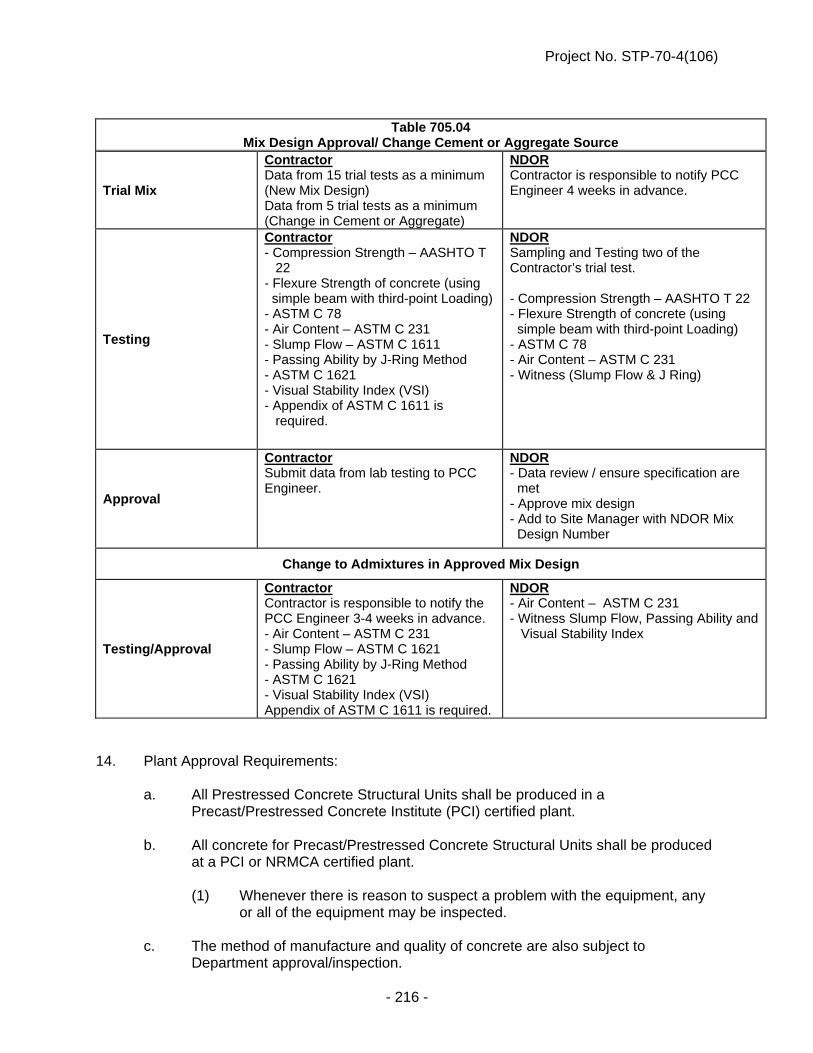
Project No. STP-70-4(106)
- 216 -
14. Plant Approval Requirements: a. All Prestressed Concrete Structural Units shall be produced in a
Precast/Prestressed Concrete Institute (PCI) certified plant. b. All concrete for Precast/Prestressed Concrete Structural Units shall be produced
at a PCI or NRMCA certified plant. (1) Whenever there is reason to suspect a problem with the equipment, any
or all of the equipment may be inspected. c. The method of manufacture and quality of concrete are also subject to
Department approval/inspection.
Table 705.04 Mix Design Approval/ Change Cement or Aggregate Source
Trial Mix
Contractor Data from 15 trial tests as a minimum (New Mix Design) Data from 5 trial tests as a minimum (Change in Cement or Aggregate)
NDOR Contractor is responsible to notify PCC Engineer 4 weeks in advance.
Testing
Contractor - Compression Strength – AASHTO T 22 - Flexure Strength of concrete (using simple beam with third-point Loading) - ASTM C 78 - Air Content – ASTM C 231 - Slump Flow – ASTM C 1611 - Passing Ability by J-Ring Method - ASTM C 1621 - Visual Stability Index (VSI) - Appendix of ASTM C 1611 is required.
NDOR Sampling and Testing two of the Contractor’s trial test. - Compression Strength – AASHTO T 22 - Flexure Strength of concrete (using simple beam with third-point Loading) - ASTM C 78 - Air Content – ASTM C 231 - Witness (Slump Flow & J Ring)
Approval
Contractor Submit data from lab testing to PCC Engineer.
NDOR - Data review / ensure specification are met - Approve mix design - Add to Site Manager with NDOR Mix Design Number
Change to Admixtures in Approved Mix Design
Testing/Approval
Contractor Contractor is responsible to notify the PCC Engineer 3-4 weeks in advance. - Air Content – ASTM C 231 - Slump Flow – ASTM C 1621 - Passing Ability by J-Ring Method - ASTM C 1621 - Visual Stability Index (VSI) Appendix of ASTM C 1611 is required.
NDOR - Air Content – ASTM C 231 - Witness Slump Flow, Passing Ability and Visual Stability Index

Project No. STP-70-4(106)
- 217 -
d. A Contractor proposing to furnish Precast or Precast/Prestressed Structural Units
shall submit the following additional details to the Department concerning the method of manufacture:
(1) Type, number, size, and location of the prestressing elements, and the
name of the manufacturer of the post-tensioning or pretensioning elements.
(2) Complete information as to type, size, and method of installation of
devices for anchoring post-tensioning elements. (3) The proposed manufacturing methods and the plans and design details of
proposed casting beds and forms. e. The use of portable pretensioning beds for the manufacture of concrete structural
units or piles will not be allowed. 15. Mix Design Approval Requirements: a. The results of 15 individual trial mixes shall be produced using the same process
as the plants normal production run. All test results of individual trial mixes shall be given to the Engineer. The test results collected shall include the following:
(1) The release and 28-day compressive strength test results shall conform
to AASHTO T 22. (2) The water/cement ratio. (3) The air content (between 2.0 percent and 6.0 percent inclusive). (4) The cement, fly ash, Slag Cement and Silica Fume content. (5) The amount of fine aggregate, coarse aggregate, and sand and gravel. (6) Slump Flow test results shall conform to ASTM C 1611 (7) Passing Ability by J-Ring Method test results shall conform to ASTM
1621. (8) Visual Stability Index (VSI) test results shall conform to the Appendix of
ASTM C 1611. (9) Flexure Strength of concrete at 28-day test results shall conform to (using
simple beam with third-point loading) ASTM C 78. b. Any change of cement or aggregate source which must be on the NDR Approved
Product List shall require 5 new individual trial mixes. Refer to Table 705.04 for required testing procedures.
c. Any changes using admixtures, the Contractor shall verify the properties of the
concrete. Refer to Table 705.04 for the required testing procedures.

Project No. STP-70-4(106)
- 218 -
d. The compressive strength test results of 15 individual trial mixes shall be
performed by the Contractor. An individual trial mix shall consist of two sets of three cylinders with three cylinders being averaged at release and at 28-day. One set shall be taken within the first third of the load and the second set shall be taken within the two thirds of the load.
e. All tests for elastic modulus and compressive strength will be conducted using
4 inch x 8 inch (100 mm x 200 mm) cylinders. f. The flexure strength test results of 15 individual trial mixes shall be performed by
the Contractor. An individual trial mix shall consist of two sets of two beams with two beams being averaged at 28-day. One set shall be taken within the first third of the load and the second set shall be taken within the two thirds of the load.
Construction Methods 1. The Contractor shall construct Precast or Precast/Prestressed Structures and piles as
shown in the plans. 2. The Contractor shall provide the Engineer a 4-week production schedule that is updated
as necessary. If the Engineer is given less than 1 NDOR work day notice of a schedule change, then the fabricator may not proceed until the Engineer has reviewed the change. The Engineer may observe any or all of the procedures and shall have access to all reported data at any time during fabrication. The Engineer shall report any inconsistencies to the job superintendent.
3. The concrete producer shall report the following information for each load of concrete
used to fabricate girders: a. Brand, mill, type, certified test number, and weight of cement. b. Brand, mill, class, certified test number, and weight of fly ash. c. Type, source, location, weight, and free moisture content for each aggregate.
Aggregate moisture shall be determined according to NDR T 506 for each half day.
d. Source, type, name, and amount of each admixture. e. Water added during batching and at placement site. f. Time water and cement are initially mixed into the batch. g. Time placement is completed.

Project No. STP-70-4(106)
- 219 -
4. Tensioning:
a. Methods: (1) In all methods of tensioning, the stress induced in the prestressing
elements shall be measured by the Contractor both with jacking gauges and by elongation of the elements; and these results shall be the same within a 5% tolerance.
(2) Means shall be provided for measuring the elongation of reinforcement to
at least the nearest 1/8 inch (3 mm). (3) All steel stressing devices, whether hydraulic jacks or screw jacks, shall
be equipped with accurate reading calibrated pressure gauges, rings, or other devices as applicable to the jack being used.
(4) All devices shall be calibrated and, if necessary, recalibrated so as to
allow the stress in the prestressing steel to be computed at all times. (5) A certified calibration curve shall accompany each device. (6) Safety measures must be taken by the Contractor to prevent accidents
due to possible breaking of the prestressing steel or the slipping of the grips during the prestressing process.
b. Measurement: (1) Pressure gauges, load cells, dynamometers, and any other devices used
in determination of loads and/or pressures shall be accurate in their effective range within a 2% tolerance.
(2) Such equipment shall be calibrated by an approved testing laboratory. (3) The Contractor's laboratory shall furnish calibration curves for each
device and shall certify the curves as being accurate and verifiable. (4) The calibration of tensioning devices shall be accomplished in place. (5) The configuration of jacks, gauges, and other components during
calibration shall be exactly the same as during the actual stressing operation.
(6) The method of calibration shall be as approved by the Engineer. (7) Tensioning devices shall be calibrated at least once a year and at any
time a system appears to be operating in an erratic or inaccurate manner or gauge pressure and elongation measurements fail to correlate.
c. If the strand tension indicated by the gauge pressure and by elongation methods
fail to agree within 5%, the operation shall be carefully checked and the source of error determined before proceeding further.

Project No. STP-70-4(106)
- 220 -
d. Measurement Consideration: (1) The Contractor's elongation and jacking pressure measurements shall
make appropriate allowance for friction and all possible slippage or relaxation of the anchorage.
(2) For pretensioned members, independent references shall be established
adjacent to each anchorage by the Contractor to indicate any yielding or slippage that may occur between the time of initial stressing and final release of the cables.
(3) The Contractor may tension straight post-tensioned tendons from one
end. Curved tendons shall generally be stressed by simultaneous jacking from both ends.
e. In all stressing operations, the Contractor shall keep stressing force symmetrical
about the member's vertical axis. 5. Stressing Procedure: a. Prestressing methods are shown in the plans. When the Contractor elects to use
a method other than that shown in the plans, the Contractor shall submit complete shop plans for the proposed method.
b. Pretensioning Method: (1) The amount of stress to be given each strand by the Contractor shall be
as shown in the plans. (2) All strands to be prestressed in a group shall be brought to a uniform
initial tension before being given their full pretensioning. This uniform initial tension of approximately 1,000 to 2,000 pounds (450 to 900 kg) shall be measured by a dynamometer or other approved means so that it can be used as a check against the computed and measured elongation.
(3) After initial tensioning, either single strand or multiple strand groups shall
be stressed until the required elongation and jacking pressure are attained and reconciled within the 5% tolerance.
(4) With the strand stressed in accordance with the plan requirements and
these Specifications, and with all other reinforcing in place, the Contractor shall cast the concrete to the lengths desired. Strand stress shall be maintained between anchorages until the concrete has reached the compressive strength specified in the plans.
c. Post-tensioning Method - For all post-tensioned elements, the Contractor shall
set the anchor plates exactly normal in all directions to the axis of the bar or tensioning strand. Parallel wire anchorage cones shall be recessed within the beams. Tensioning shall not be done until the concrete has reached the compressive strength specified in the plans.

Project No. STP-70-4(106)
- 221 -
d. Combined Method - In the event that the girders are manufactured with part of the reinforcement pretensioned and part post-tensioned, the applicable portions of the requirements listed above shall apply to each type.
6. Forms: a. Forms for Precast or Precast/Prestressed Concrete Structural Units shall
conform to the requirements for concrete formwork as provided in Subsection 704.03.
b. Precast or precast/prestressed forms shall be accessible for the vibration and
consolidation of concrete. c. If the ambient temperatures are above 90oF (32oC), precautions shall be taken so
the forms, reinforcing steel and steel beams of structural units will be the ambient temperature.
7. Placing Concrete: a. The Contractor shall provide the Department a 4-week production schedule that
is updated as necessary. Unscheduled production changes may delay fabrication. Unscheduled production may result in rejection of Precast or Precast/Prestressed Concrete Structural Units.
b. The Engineer may observe any or all of the procedures. The Contractor shall
provide access to all reported data at any time during fabrication. The Engineer will report any inconsistencies to the job superintendent.
c. Concrete shall not be placed before completing the forming and placing of
reinforcement. d. Placing Procedure: (1) Concrete shall be placed continuously in each unit, taking care to avoid
horizontal or diagonal planes of weakness. (2) However, if there is a delay in delivery of concrete or for some other
reason placement is interrupted for more than 30 minutes, then the concrete shall be rejected.
e. Consolidation:
(1) Whether concrete requires vibration or self-consolidating concrete is
used, special care shall be exercised to work and consolidate the concrete around the reinforcement and to avoid the formation of stone pockets, honeycombs and other defects.
(2) Self-consolidated concrete (SCC) shall not be vibrated. Rodding of Self-
Consolidated Concrete (SCC) is permissible in areas of tight reinforcement.
(3) The other concrete shall be consolidated by vibrating.

Project No. STP-70-4(106)
- 222 -
f. The concrete shall be a homogenous mixture and shall not contain cement balls. g. The forms shall be overfilled, the excess concrete screeded off, and the top
surfaces finished to a uniform, even texture. h. Each Precast or Precast/Prestressed Concrete Structural Unit shall be stamped
or marked with an identification number and its manufacture date. i. Environmental Limitations: (1) The optimum range of concrete temperatures from the time the concrete
is completely mixed until the beginning of the presteam segment of the steam curing cycle shall be 50° to 95°F (10° to 35°C). Failure to operate within the optimum range shall be cause for curtailment of operations. During the presteam segment of the curing cycle, the temperature of the concrete shall not exceed 100°F (38°C) nor fall below 50°F (10°C). These temperature restrictions apply when heat is supplied to the curing enclosure prior to initial set.
(2) When placing concrete under cold weather conditions (ambient air
temperature less than 36°F [2°C]), the Cold Weather Specifications in Sections 1002 and 704 shall be followed.
(3) Forms and reinforcing materials shall be preheated to a minimum
temperature of 40°F (4°C) and a maximum temperature not to exceed that of the concrete at the time of placement.
(4) The Contractor may preheat the drums of the mixer-trucks to the limits set
for forms and reinforcing, but under no condition shall heat be applied to the drums while they contain any of the batch materials or concrete.
8. Curing: a. General: (1) The Contractor shall cure the concrete with wet burlap, waterproof
covers, polyethylene sheets, or liquid membrane-forming compounds. Curing with liquid membrane-forming compounds shall be accomplished in accordance with the requirements of Section 1012 and Subsection 704.03, except that liquid membrane-forming compounds shall not be used on that portion of precast/prestressed concrete girders, twin tees, or bridge beams upon which concrete will be cast later.
(2) Water spray curing or other moist curing methods may be used subject to
the approval of the Engineer. (3) The period of concrete curing shall be determined by the results of the
compressive strength test on cylinders made during the progress of the work and cured to closely approximate the concrete strength of the product it represents.

Project No. STP-70-4(106)
- 223 -
(4) Side forms may be removed 12 hours after placing the concrete, provided curing is continued with one of the approved Department curing procedures.
b. Steam or radiant heat will be allowed for accelerated curing provided the
following procedure is adhered to: (1) Curing chambers shall be reasonably free of leakage and shall have a
minimum clearance of 3 inches (75 mm) in order to insure adequate circulation of heat. The relative humidity within the curing enclosure shall be maintained between 70 and 100 percent.
(2) Temperature: (i) One approved continuous recording thermometer for each
115 feet (35 m) of casting bed, with a minimum of 2 continuous recording thermometers, shall be located in each enclosure or curing chamber.
(ii) Continuous temperature record charts for each casting shall be available to the Engineer for examination and approval at any time.
(iii) If the temperature records or other temperature readings taken by the Engineer indicate that manual control of heat is producing temperature changes in excess of those specified, the Engineer may reject the Precast or Precast/Prestress Structural Unit.
(iv) Temperature of the curing concrete shall be 50°F to 105°F (10°C to 40°C) and shall be maintained near placement temperature until the concrete has reached initial set as determined by ASTM C 403 "Time of Setting of Concrete Mixture by Penetration Resistance". These temperature restrictions apply when heat is supplied to the curing enclosure prior to initial set.
(v) The temperature rate of rise shall not exceed 60°F (15.5°C) per hour.
(3) The concrete shall be completely enclosed with a waterproof curing
chamber during accelerated curing periods. (4) Steam jets shall not be directed at the concrete or the steel forms. (5) If the temperature of the concrete rises above 175°F (79°C), the concrete
shall be rejected. (6) The temperature in the concrete shall be maintained so that at any given
time the difference between the highest and lowest temperature station readings will not be more than 30°F (-1°C). If the temperature varies more than 30°F (16°C), the product shall be rejected.
(7) Eight hours after placing the concrete, individual sections may be
uncovered to remove their forms. The curing may be discontinued during this operation. The section shall not be left uncovered longer than necessary and never longer than 30 minutes. Waterproofed covers shall be used to recover the product.

Project No. STP-70-4(106)
- 224 -
(8) After the heat source has been turned off, the curing cover shall be
maintained in place during the curing period until the release strength has been reached.
(9) Detensioning shall be accomplished before the temperatures of the units
drop more than 60oF from the peak cure strength temperature and while they are still moist.
(10) Master slave heat curing system may be used for curing quality control
cylinders. c. After detensioning, prestressed concrete girders shall be inspected for cracking.
If any cracks are discovered between quarter points in the middle of the girder on the bottom flange face, the girder shall be rejected.
9. Defects and Repair Procedures: a. After the forms are removed, stone pockets, honeycombs, or other defects may
be exposed. The Engineer shall determine if these defects affect the item's structural integrity and whether the item will be rejected.
b. Precast or Precast/Prestressed Concrete Structural Units which have chipped,
spalled, honeycombed, or otherwise defective areas which are not considered detrimental to the structural integrity may be used after being repaired by the Grooming and Repair Procedures for Precast Concrete Products in the NDR Materials Sampling Guide.
10. Surface Finish: a. On structures serving as highway grade separations, the following shall apply: (1) The exterior face of all exterior girders or beams plus the bottoms and
chamfers on all lower flanges shall be given the following finish: (i) All uneven form joints in excess of 1/8 inch (3 mm) shall be
ground smooth. (ii) The surface shall be steel brushed to remove scale, laitance, and
to open partially obstructed holes. (iii) The surface shall be dampened. (iv) Grout shall be applied to the surface. (v) The grout shall consist of 1.5 parts of fine sand, 1 part of Portland
cement, and sufficient water to produce a consistency of thick paint. The cement used in the grout shall be a blend of regular Type I and white Portland cement to duplicate the lighter appearance of the steam cured units.
(vi) If necessary, an admixture which will not discolor the concrete may be used in the grout to reduce shrinkage if approved by the Engineer. Admixtures containing iron particles shall not be used.
(vii) The surface shall be float finished with a cork or other suitable float. This operation shall completely fill all holes and depressions on the surface.

Project No. STP-70-4(106)
- 225 -
(viii) When the grout is of such plasticity that it will not be pulled from holes or depressions, sponge rubber or burlap shall be used to remove all excess grout.
(ix) Surface finishing during cold weather shall not be performed unless the temperature is 40°F (4°C) and rising. The surface shall be protected against temperature drops below 40°F (4°C) for a period of 12 hours after finishing.
(x) A uniform appearance will be required. In the event the appearance produced by the above procedure is not uniform, both in texture and coloration, the Precast or Precast/Prestress Structural Unit will be rejected. The Contractor may request other methods approved by the Engineer to create a uniform appearance.
11. Grouting for Post-Tensioned Units: a. The Contractor shall install steel in flexible or other approved tubes which shall
be cast in the concrete and shall be pressure-grouted after the post-tensioning process has been completed.
b. Bonding grout shall be made to the consistency of thick paint and shall be mixed
in the proportions as follows: Portland cement (Type I), 100 pounds (45 kg); fly ash (ASTM C 618), 34 pounds (15 kg); water, 45 to 62 pounds (20 to 28 kg) (adjust at site); and nonshrink admixture approved by the PCC Engineer.
c. The final grouting pressure shall be at least 80 psi (550 kPa). d. The Contractor shall make provisions to demonstrate to the Engineer that
grouting material has completely filled all areas within the conduit. 12. Handling, Transporting, and Storing: a. (1) Prestressed Concrete Structural Units must be at least 9 days old before
they can be set on the bridge substructure. Surveying for shim shots, forming the bridge deck or diaphragms and placing construction material on the girder is not allowed until the girders have attained the minimum age and design strength specified in the plans.
(2) The Contractor shall be responsible for exercising extreme care in lifting,
handling, storing and transporting the Prestressed Concrete Structural Units to prevent cracking or damage. Prestressed concrete bridge girders shall be maintained in an upright position and supported within 18 inches of the ends at all times. When supported at the proper positions, no part of the units shall be allowed to rest on the ground. Prestressed concrete bridge girders shall be set on a level area to prevent field bowing and adequate supports shall be placed under their bearing devices to prevent settlement into the ground. Proper support bearings shall be used to avoid twisting of the prestressed concrete bridge girders. Prestressed Concrete Structural Units shall be lifted by devices designed by the Contractor.

Project No. STP-70-4(106)
- 226 -
(3) The Contractor must provide any temporary intermediate diaphragms and/or bracing necessary to provide lateral and torsional stability for the girders during construction of the concrete slab. The temporary intermediate diaphragms/bracing shall be removed after the concrete has attained its design strength. The cost of furnishing, installing and removing the temporary intermediate diaphragms and/or bracing shall be subsidiary to the pay item “Class 47BD-4000 Concrete for Bridges”.
(4) (i) The girders shall be transported in an upright position and the points of
support and direction of the reactions with respect to the girder shall be approximately the same during the transportation and storage as when the girder is in its final position. If the Contractor finds it necessary to transport the precast girders in some other position, the Contractor shall be prepared to prove that no internal damage results.
(ii) Adequate padding shall be provided between tie chains and cables to prevent chipping of the concrete.
(iii) Live loads shall not be allowed on the superstructure units until the floor slab is placed and attains the design strength shown in the plans.
13. Inspection Facilities: The Contractor shall arrange with the producer of Precast or Precast/Prestressed
Concrete Structural Units to provide an office, laboratory and bathroom for the Department's inspector. The areas shall meet the following requirements:
a. Thermostatically controlled heating and air conditioning shall be provided so that
temperature can be maintained between 68° and 77°F (20° and 25°C). b. The floors shall be tile or a similar floor covering. c. Interior and exterior walls shall be well maintained and painted. d. All exterior doors shall have cylinder locks, and all keys shall be turned over to
the Engineer. e. Ceiling lighting shall provide a minimum of 465 foot-candles (5000 lx) of light on
all working surfaces. f. Electrical outlets shall be spaced no more than 6 feet (1.8 m) apart with no less
than 1 outlet on any wall of the office or lab. g. A single trunk telephone and a means to the Internet with a minimum of 1.5 mb
of download stream shall be installed in the office, and the installation charges shall be paid by the Contractor. The monthly service charges will be paid by the Department.
h. A fire extinguisher and First-Aid kit shall be provided. i. A ventilated bathroom with a toilet and sink shall be provided in the structure. A
fresh water supply and drain will be required in the lab area.

Project No. STP-70-4(106)
- 227 -
j. The lab, office, and bathroom shall be separate rooms with interconnecting doors.
k. The minimum lab area is 230 square feet (21 m2). l. The minimum toilet area is 20 square feet (2 m2). m. The minimum office area is 160 square feet (15 m2). n. The Contractor shall clean and maintain the rooms and shall supply all heating
fuel, electricity, and water. o. The Contractor shall also supply for the sole use of the inspectors all desks, work
tables, chairs, files, lockers, and sanitary supplies necessary and commensurate with the inspection of his/her plant. It is anticipated that the following minimum amount of office and lab equipment will be required: One desk with approximately 3 foot x 6 foot (0.9 m x 1.8 m) top; one upright locker or wardrobe, with shelves, approximately 5 feet (1.5 m) deep; two 4-drawer file cabinets; 1 chair per inspector; 10 square feet (1 m2) of work surface per inspector in the office area; and a lab counter (approximately 3 x 18 feet [0.9 m x 5.5 m]) with storage space beneath.
Method of Measurement 1. Precast or Precast/Prestressed Concrete piles shall be measured in accordance with the
requirements of Section 703. 2. Precast or Precast/Prestressed Concrete superstructures will be measured for payment
by the lump sum. Basis of Payment 1. Prestressed and/or Precast Concrete piles shall be measured and paid for as prescribed
in Section 703. 2. Pay Item Pay Unit Precast/Prestressed Concrete Lump Sum (LS) _____ Superstructure at Station ______* * Reinforcing steel, prestressing tendons, and all other components of the Precast or
Precast/Prestressed Concrete superstructure are subsidiary to this pay item. 3. The cost of furnishing and maintaining the inspection facilities will not be paid for directly,
but shall be subsidiary to "Precast/Prestressed Concrete _____ Superstructure at Station _____".
4. If a Precast or Precast/Prestressed Structural item's 56-day compressive strength is less
than the design strength, then the Engineer will determine if the item can be used. If the item is to be used, a payment deduction of 25% will be taken if the 56-day compressive strength is less than 95 percent of the design strength.

Project No. STP-70-4(106)
- 228 -
5. All equipment calibrations and tests are subsidiary to "Precast/Prestressed Concrete _____ Superstructure at Station _____".
6. Payment is considered full compensation for all work prescribed in this Section, including
the cost of prestressing and precasting.
DEBONDING PRESTRESSING STRANDS (G-15-0612)
General Where shown, debond prestressing strands by encasing the strands in plastic sheathing along the entire length shown and sealing the ends of the sheathing with waterproof tape. Materials Sheathing must: 1. Be split or un-split flexible polymer plastic tubing
2. Have a minimum wall thickness of 0.025 inch
3. Have an inside diameter exceeding the maximum outside diameter of the strand by 0.025 to 0.14 inch
4. Not react with the concrete or steel Split sheathing must have a minimum overlap of 3/8 inch. Waterproofing tape must be flexible adhesive tape. Construction Distribute the debonded strands symmetrically about the vertical centerline of the girder. The debonded lengths of pairs of strands must be equal. Do not terminate debonding at any one cross section of the member for more than 40 percent of the debonded strands or 4 strands, whichever is greater. Do not debond the outside strands. Thoroughly seal the ends of the sheathing encasing the strand with waterproof tape before placing the concrete to prevent the intrusion of water or cement paste. Do not debond the extended strands. Payment Full compensation for Debonding Prestressing Strands shall be considered as included in the contract price paid for the Pay Item “Precast-Prestressed Concrete Superstructure at Sta ___”, and no separate payment will be made.

Project No. STP-70-4(106)
- 229 -
EXPANSION BEARINGS, PTFE TYPE (G-16-1213)
Section 712 in the Standard Specifications is amended to provide that all references to Expansion Bearings, TFE Type shall be considered as Expansion Bearings, PTFE Type. Paragraph 2.a. of Subsection 712.02 is void and superseded by the following:
2. Expansion Bearings, PTFE Type:
a. (1) The upper assembly shall consist of a sole plate conforming to the requirements of ASTM A709/A709M grade 50W (345W) weathering steel with an ASTM A240/A240M Type 304 stainless steel plate (13 gage) attached to the lower surface. As an alternate, the sole plate may be grade 36 (250) steel, metallized. If the grade 36 alternate is used, all flame cut edges of the sole plate shall be ground to reduce hardness and facilitate blast cleaning. All corners of the sole plate shall be rounded to a 1/16 inch (1.5 mm) radius. All exposed plain steel surfaces shall be blast cleaned to a near white finish and zinc metallized with a minimum thickness of 8 mils (200 mm). Zinc metallizing must be performed in accordance with the American Welding Specification AWS C2.2.
Paragraph 2.b.(4) of Subsection 712.02 is void and superseded by the following: The PTFE sheet shall conform to the requirements of the AASHTO LRFD Bridge Design Specifications and the Standard Specifications.
BRIDGE JOINT NOSING (G-17-1113)
Description This work shall include sawing, removals (including existing angle irons), forming, and placing of the bridge joint nosing materials required at the expansion joint locations, as specified in the plans. This provision applies to: - New construction, such as when a new approach slab is being constructed - Breaking out concrete bridge deck or approaches and building new expansion joint
seat - Saw cutting existing concrete to allow installation of a new expansion joint - Repairing broken edges of expansion joint gaps such as with nosing material - Asphalt overlays on bridge decks and approaches Material Requirements Products for repair of expansion joint seats or gap edges or used to enhance the durability of gap edges are known as nosing materials. Such materials are given on the Approved Products List as “Bridge Joint Nosing Materials”. Products not shown on the Approved Products List may be used as allowed by Materials and Research Division.

Project No. STP-70-4(106)
- 230 -
Equipment Appropriate equipment, in good working order shall be employed to ensure proper mixing and timely application of nosing materials. Construction Methods Construction of expansion joint seats shall be done as shown in the plans and compliant with all applicable Special Provisions. All faces of the joint gap or seat shall be laid out in a straight line (shall not deviate from a straight line by more than ¼ inch at any point). This rule is applicable to whatever method is used to construct the gap, whether it is saw cutting, concrete forming, placing nosing material, etc. Nosing materials shall be used as prescribed by the manufacturer. In addition, or to augment the manufacturer’s instructions as to preparation, all concrete surfaces against which repair or reconstruction material is to be placed, shall be thoroughly cleaned and free of all dust, laitance, moisture or any substances that may interfere with proper adhesion of the material to the concrete. Concrete against which nosing materials are applied shall have been cured for a period as specified by the nosing manufacturer. Method of Measurement The quantity of nosing for which payment will be made shall be computed by the Department in cubic feet from dimensions shown in the plans. No field measurement is required unless actual geometry deviates substantially from what is shown in the plans. No deduction shall be made for the amount of material displaced by reinforcement. Basis of Payment The Bridge Joint Nosing shall be paid by the cubic foot of the nosing installed and accepted by the Engineer. Preparation of the joint, including sawing, removals, sandblasting and forming will not be paid for directly but shall be considered subsidiary to the Bridge Joint Nosing. Pay Item Pay Unit Bridge Joint Nosing Cubic Feet (CF)
BACKFILLING CULVERTS (G-43-0216)
Paragraph 10.6, of Subsection 107.07 in the Standard Specifications is void. Subsection 702.03, Paragraph 3.a. is amended to include the following: (13) Backfill for culverts shall not be placed on frozen soil.

Project No. STP-70-4(106)
- 231 -
Subsection 702.03, Paragraph 3.c.(4) is void and superseded by the following:
(4) Backfill for traffic:
(i) Culverts having 2 feet or more depth of excavation, within 15 feet of traveled way shall be backfilled to 15 feet minimum from the edge of the traveled way prior to removing traffic control. Backfill for traffic shall be to the final grade or to the limits shown in Figure 702.01. Additional excavation for culverts may be required.
(ii) The Engineer may also determine that it is necessary or desirable to allow vehicles (construction or otherwise) to travel over a pipe or box culvert. The volume to be compacted adjacent to the pipe or box culvert shall be that between vertical planes located 5 feet (1.5 m) outside of and parallel to the neat lines of the pipe or barrel at its maximum horizontal dimension and a 1 vertical to 6 horizontal slope to natural ground line. Compacted soil shall be placed to a depth at least 3 feet (1 m) above the top of the box or pipe and to the grade of the existing adjacent shoulder slope on extensions. The remaining length of the pipe or box culvert shall be filled in accordance to pipe culverts in 702.03 Paragraph 3.f.(3).
(iii) After the pipe is laid or as soon as the box culvert concrete reaches 3000 psi compressive strength, the Contractor shall complete the backfill within 10 calendar days.
(iv) Failure to complete the backfill within 10 calendar days shall be cause for the assessment of liquidated damages in the amount of $500 per working day until the backfill is completed. “Completion of the backfill” shall be defined as the time when all of the required material has been placed, compacted, and shaped.
(v) The Engineer may extend the 10 calendar days because of weather and soil conditions.
(vi) The assessment of all liquidated damages described in Section 702 shall be in addition to any applicable liquidated damages assessed in accordance with Subsection 108.08.
Subsection 702.04, Paragraph 7.a. and b. is void and superseded by the following:
7. a. Backfill required by paragraph 3.c.(3) and (4) of Subsection 702.03 is measured and paid as “Excavation for Pipe, Pipe-Arch Culverts and Headwalls” or “Excavation for Box Culverts”.
b. Backfill beyond the limits in Paragraph 3.c.(3) and (4) of Subsection 702.03 is paid for under the pay item for the remainder of the surrounding embankment.
Subsection 702.05, Paragraph 5. is void and superseded by the following:
5. a. Additional excavation for backfill and embankment for pipe culverts, headwalls, and box culverts will be paid at the item’s

Project No. STP-70-4(106)
- 232 -
contract unit price – “Excavation for Pipe or Pipe-Arch Culverts and Headwalls” and “Excavation for Box Culverts”.
b. Embankment placed above the limits specified in Subsection
702.03, Paragraph 3.c.(4) shall be included with the appropriate earthwork pay item [“Excavation”, “Excavation Borrow”, “Excavation (Established Quantities)”, “Earthwork Measured in Embankment”].
c. The quantity of additional excavation for culvert backfill shall be
subtracted from the appropriate earthwork pay item, if applicable [“Excavation”, “Excavation Borrow”, “Excavation (Established Quantities)”, “Earthwork Measured in Embankment”].
REMOVE STRUCTURE AT STATION 115+44.54
General Items The item, "Remove Structure at Station 115+44.54, 8.5’ Rt. " shall be in accordance with the pertinent provisions of Section 203 of the Standard Specifications. Phasing Items The existing structure will be used to maintain traffic during Phase I Construction. The removal of the existing structure shall be done in phases according to the details shown on the plans.
Figure 702.01

Project No. STP-70-4(106)
- 233 -
Disposal of Materials Items The Contractor shall take adequate precautions to protect traffic at all times during the bridge removal process. Broken concrete resulting from the removal shall be made available for use as riprap, as shown on the plan. If the existing concrete deck is covered with bituminous overlay and the material is to be used as broken concrete riprap, the overlay shall be removed prior to the removal of the structure. No bituminous material may be used as broken concrete riprap. Lead-Based Paint Removal Items All structural steel on the existing bridge was painted with a lead paint. All other work involved with the removal and handling of this structural steel shall be in accordance with Section 732 of the Standard Specifications. The paint on the bridge railing contains lead. All other work involved with the removal and handling of this structural steel shall be in accordance with Section 732 of the Standard Specifications. If there are lead plates under the existing steel rail posts, the Contractor shall recycle the lead plates at a legitimate recycling facility as specified in Paragraph 3 (Environmental Requirements) in Subsection 203.01 of the Standard Specifications.
EXPANSION DEVICE INSTALLATION Any expansion device installation that fails to meet manufacturer’s installation specifications will be removed and replaced with a properly installed joint at the expense of the Contractor. No payment will be made unless the manufacturer’s representative certifies the installation.
BRIDGE SHORING
Paragraph 1 of Subsection 701.02 in the 2007 Standard Specifications is void and superseded by the following: 1. a. The Contractor shall excavate and place shoring, as necessary, to insure safe access to
work areas. b. (1) Adequate shoring must be installed by the Contractor during phased construction to
retain the existing and proposed roadway fill. (2) The shoring shall be in place before starting the grading work for the first phase of
construction. (3) The shoring shall not be exposed to traffic at any time.

Project No. STP-70-4(106)
- 234 -
(4) Shoring shall be designed by a Professional Engineer registered in the State of Nebraska.
(5) The calculations and shoring plans shall bear the seal of the designer and four
copies of each shall be submitted to the Engineer before construction. These calculations and plans will be for informational purposes only. The Contractor is solely responsible for the satisfactory construction and performance of the shoring.
(6) Shoring indicated in the plans as bridge shoring will not be pulled. Any removal
required shall be made by flame cutting unless approved otherwise by the Engineer. Flame cutting will be to a minimum of 4 in. below the bottom of the roadway paving or approach slabs and as required to allow construction of the abutments or grade beams.
(7) Shoring indicated in the plans as temporary bridge shoring shall be removed by the
Contractor. (8) Bridge shoring and temporary shoring shall be measured for payment by the lump
sum and paid for as “Bridge Shoring” and “Temporary Bridge Shoring”. This price shall be full compensation for designing, furnishing, installing, maintaining and removing the temporary shoring and for all labor, materials, equipment, tools and incidentals necessary to complete the work.
CONCRETE CONSTRUCTION
Paragraph 3. of Subsection 704.04 of the Standard Specifications for Highway Construction is void and superseded by the following: 3. The volume of concrete piles, cast-in-place concrete piles or steel pipe piles encased in
the concrete has not been included in the concrete plan quantity.
CRUSHED ROCK BASE COURSE FOR CONCRETE BOX CULVERTS
Section 717 in the Standard Specifications is amended to include the following: The Contractor shall use crushed rock as a base for the floor of the box culvert as shown in the plans. The non-woven geotextile fabric shown in the plans shall be a Class 1 Non Woven Geotextile shown on the Approved Products List. Crushed rock should be coarse crushed rock (1-1/2” maximum size) and shall meet the general aggregate properties of Paragraph 2. of Subsection 1033.02. The item “Crushed Rock For Base Course” shall be measured and paid for by the Cubic Yard. Payment for the Crushed Rock For Base Course shall include the crushed rock and any additional labor or materials necessary to construct the base.

Project No. STP-70-4(106)
- 235 -
The item “Non-Woven Geo-Fabric” will be measured and paid for by the square yard. Payment shall be considered full compensation for all work prescribed.
JACKING CULVERT PIPE, SEWER PIPE, AND CASING
Subsection 731.05 in the Standard Specifications is amended to include the following: Pay Item Pay Unit Jacking ____ inch Culvert Pipe, Type ___, Class ___ Linear Foot (LF)
CONTRACTOR’S ACCESS BRIDGE
It will be the contractor’s option to use an access bridge for a temporary crossing to construct the bridge on this project. It shall be required that the absolute “low steel” for the Contractor’s Access Bridge shall be above elevation 2017.3. It will be the contractor’s responsibility to submit a plan of the access bridge to the Department of Roads Environmental Unit, who will forward the plan to the Corps of Engineers for approval. Construction of the access bridge will not begin until written approval has been received from the Corps of Engineers. The Contractor should not expect to receive approval from the Corps of Engineers prior to the letting. Bidders must submit a bid for the item “Access Bridge at Sta ___” in the schedule of items. The item “Access Bridge at Sta ___” will be paid for as a lump sum. The bid price shall be considered full compensation for all work required for the contractor to construct, maintain, and remove the access bridge. The contractor will only be paid for this item if they construct the access bridge. The contractor will be paid 90% of the lump sum when the access bridge is installed. The remaining 10% of the lump sum will be paid when the access bridge is removed. Crushed rock surfacing and erosion control items necessary for building and maintaining the approaches to the access bridge will not be paid for directly, but shall be considered subsidiary to the item “Access Bridge at Sta ___”. If the Contractor does not plan to utilize an access bridge, they shall bid the item “Access Bridge at Sta ___” at $0. If the contractor bids this item at $0 and later decides to utilize an access bridge, it will be at the contractor’s expense. No change orders will be approved to increase the cost of the “Access Bridge at Sta ___” item after award of the contract.

Project No. STP-70-4(106)
- 236 -
SEEDING
Subsection 803.02 in the Standard Specifications is amended to include the following:
Type “B” Minimum
Purity
Broadcast
Application Rate in lb. of Pure Live
Seed/Acre
Approved Mechanical Drill
Application Rate in lb. of Pure Live
Seed/Acre Perennial ryegrass – Linn, Norlea, Amazon 85 7 Slender wheatgrass 85 5 K-31 fescue 85 3.5 Western wheatgrass – Flintlock, Barton 85 7 Blue grama – NE, KS, CO, MN, SD 30 2 Buffalograss – Sharp’s Improved, Bison, Texoka, Cody
80 5
Sideoats grama – Butte, Trailway 75 4 Sand lovegrass – Nebraska-27, native 90 0.75 Oats/wheat (wheat in the fall) 90 17
All seed shall be origin Nebraska, adjoining states, or as specified. A contractor proposing to use a substitute variety, or origin shall submit for the engineer’s consideration a seed tag representing the seed which shows the variety, origin and analysis of the seed. Rate of application of commercial inorganic fertilizer shall be: Rate of Application per
Acre (Minimum) Available Nitrogen (N2) 19 or 36 lbs.
Available Phosphoric Acid (P2O5) 0 lbs.
Rate of application of granular sulphur coated urea fertilizer shall be: Nitrogen (Total Available) 0 lbs.
The contractor may, at his option, apply granular urea formaldehyde in lieu of the sulphur coated urea fertilizer at the following rate: Nitrogen (Total Available) 0 lbs.

Project No. STP-70-4(106)
- 237 -
SEEDING
Subsection 803.02 in the Standard Specifications is amended to include the following:
Type “Buffer” Minimum
Purity
Broadcast
Application Rate in lb. of Pure Live
Seed/Acre
Approved Mechanical Drill
Application Rate in lb. of Pure Live
Seed/Acre Canada wildrye – Mandan, NE, IA 85 5 Virginia wildrye – Omaha, native 85 3 Western wheatgrass –Flintlock, Barton 85 2.5 Slender wheatgrass 85 2.5 Sideoats grama – Butte, Trailway 75 3 Big bluestem – Bonanza, Pawnee, Roundtree 60 3 Indiangrass – Holt, Nebraska-54 60 2 Little bluestem – Aldous, Blaze, Camper 60 2 Prairie cordgrass (Spartina pectinata) 85 0.75 Switchgrass – Pathfinder, Blackwell, Nebraska-28 Trailblazer
90 0.5
Sand lovegrass – Nebr. 27, Native 90 0.3 Purple prairie clover – Kaneb, inoculated 85 0.1 Blackeyed Susan (Rudbeckia hirta) 90 0.2 Shell-leaf penstemon (Penstemon grandiflorus)
75 0.15
New England aster (Aster novae-angliae) 85 0.2 Butterfly milkweed (Asclepias tuberosa) 75 0.3 Oats/Wheat (in the fall) 90 15 All seed shall be origin Nebraska, adjoining states, or as specified. A contractor proposing to use a substitute variety, or origin shall submit for the engineer’s consideration a seed tag representing the seed which shows the variety, origin and analysis of the seed. Rate of application of commercial inorganic fertilizer shall be: Rate of Application per
Acre (Minimum) Available Nitrogen (N2) 0 lbs.
Available Phosphoric Acid (P2O5) 0 lbs.
Rate of application of granular sulphur coated urea fertilizer shall be: Nitrogen (Total Available) 0 lbs.
Paragraph 6. of Subsection 803.02 is void and superseded by the following: 6. Mulch shall be hay mulch as prescribed in Section 805.

Project No. STP-70-4(106)
- 238 -
SEEDING
Subsection 803.02 in the Standard Specifications is amended to include the following:
Type “Wetland High” Minimum
Purity
Broadcast
Application Rate in lb. of Pure Live
Seed/Acre
Approved Mechanical Drill
Application Rate in lb. of Pure Live
Seed/Acre Canada wildrye – Mandan, NE, IA 85 3 2.5 Bluejoint (Calamagrostis canadensis) 65 0.2 0.2 Fox sedge (Carex vulpinoidea) 85 0.6 0.5 Short-beaked sedge (Carex brevior) 85 0.75 0.75 Switchgrass – Blackwell, NE-28, Trailblazer, Pathfinder
90 0.75 0.5
Big bluestem – Pawnee, Bonanza, Roundtree 60 2.5 2 Indiangrass – Holt, NE-54 75 2 2 Prairie cordgrass (Spartina pectinata) 75 3 2.5 Cup plant (Silphium perfoliatum) 75 0.5 0.3 Canada anemone (Anemone canadensis) 65 0.3 0.25 New England aster (Aster novae-angliae) 75 0.3 0.2 Blue vervain (Verbena hastata) 75 0.2 0.1 Black-eyed Susan (Rudbeckia hirta) 90 0.2 0.15
Type “Wetland Low” Minimum
Purity
Broadcast
Application Rate in lb. of Pure Live
Seed/Acre
Approved Mechanical Drill
Application Rate in lb. of Pure Live
Seed/Acre Bluejoint (Calamagrostis canadensis) 65 0.3 0.25 Awl-fruited sedge (Carex stipata) 85 0.75 0.6 Fox sedge (Carex vulpinoidea) 85 1 0.75 Green bulrush (Scirpus atrovirens) 85 0.2 0.2 Spike rush (Eleocharis palustris) 60 0.25 0.2 Giant bur reed (Sparganium eurycarpum) 75 1 1 Soft-stem bulrush (Schoenoplectus tabernaemontani)
75 0.6 0.5
Rice cutgrass (Leersia oryzoides) 50 0.35 0.3 Arrowhead (Sagittaria cuneata) 80 5 4 Water plantain (Alisma plantago-aquatica) 80 1.25 1 Swamp milkweed (Asclepias incarnata) 90 0.4 0.2 Scarlet smartweed (Polygonum coccineum) 75 0.5 0.4 New England aster (Aster novae-angliae) 75 0.3 0.2 Beggartick (Bidens cernua) 90 0.6 0.5 All seeds shall be origin Nebraska, adjoining states, or as specified. A contractor proposing to use a substitute variety shall submit for the engineer’s consideration a seed tag representing the seed, which shows the variety, origin and analysis of the seed.

Project No. STP-70-4(106)
- 239 -
Rate of application of inorganic fertilizer shall be: Rate of Application per
Acre (Min.) Available Nitrogen (N2) 0 lb. Available Phosphoric Acid (P2O5) 0 lb. Rate of application of granular sulphur coated urea fertilizer or urea-formaldehyde fertilizer shall be: Rate of application per
Acre (Min.) Nitrogen (Total Available) 0 lb. Paragraph 6. of Subsection 803.02 is void and superseded by the following:
6. Mulch shall be Hydromulch as prescribed elsewhere in these Special Provisions.

Project No. STP-70-4(106)
- 240 -
EROSION CONTROL Subsection 807.01 in the Standard Specifications is void and superseded by the following: This work shall consist of the preparation of slopes and waterways and the furnishing
and application of soil retention blankets at the locations shown in the plans. Paragraphs 2., 2.a., 2.b. and 2.c. of Subsection 807.02 are void and superseded by the
following: Wire staples shall be used for anchoring the soil retention blanket. The staples shall be
a minimum of 13 gauge U-shaped steel wire with a 1 inch or larger throat with at least 6 inch long legs.
Paragraph 5. of Subsection 807.02 is void. Subsection 807.02 is amended to include the following:
Minimum Purity (%)
Application rate in lb. of Pure Live Seed/1000 yd.²
Perennial ryegrass – Linn, Norlea, Amazon 85 1.25
Western wheatgrass – Barton, Flintlock 85 1.25
Slender wheatgrass 85 1
Canada wildrye – Mandan, Homestead, NE native 85 1
K-31 fescue 85 0.6
Sideoats grama – Butte, Trailway 75 0.75
Switchgrass – Blackwell, Cave-in-Rock, Nebraska-28, Trailblazer,
Pathfinder
90 0.5
Sand lovegrass – Nebraska-27, native 90 0.2
Little bluestem – Nebr. native, Camper, Pastura, Cimarron 60 0.5
Prairie cordgrass (Spartina pectinata) 75 0.3
Blue flax (Linum lewisii) 85 0.3
Mexican red hat (Ratibida columnifera, red) 85 0.1
Oats/wheat (wheat in the fall) 90 5
All seeds shall be origin Nebraska, adjoining states, or as specified. A Contractor proposing to use a substitute variety or origin shall submit for the Engineer’s consideration a seed tag representing the seed, which shows the variety, origin and analysis of the seed.

Project No. STP-70-4(106)
- 241 -
Rate of application of inorganic fertilizer shall be:
Rate of Application
Per 1000 yd.² (Min.)
Available Nitrogen (N2) --------------------------------- 4 or 9 lb.
Available Phosphoric Acid (P2O5) -------------------- 0 lb.
Rate of application of granular sulphur coated urea fertilizer or urea-formaldehyde fertilizer shall be:
Rate of Application
Per 1000 yd.² (Min.)
Nitrogen (Total Available) ------------------------------ 0 lb.
Paragraph 6.c. of Subsection 807.03 is void. Paragraphs 7.a.i. and 7.a.ii. of Subsection 807.03 are void. Paragraph 8. of Subsection 807.03 is void. Paragraph 1. of Subsection 807.05 is amended to include the following: Pay Item Pay Unit Erosion Control, Class ____ Square Yard (SY)
COVERCROP SEEDING (H-14-0515)
Subsection 812.01 Paragraph 2. is void and superseded by the following: Cover crop seeding shall be applied to any disturbed area requiring erosion
protection. It is intended to be used in staged construction areas, surcharge areas, or other disturbed areas that have not been permanently seeded.
Subsection 812.02 Paragraph 4. is void.

Project No. STP-70-4(106)
- 242 -
Subsection 812.04 is void and superseded by the following: Subsection 812.04 1. Cover crop seeding is measured by the acre of ground surface seeded. The
areas will be calculated from surface measurements of the length and width + 1 yard (+ 900 mm).
MULCH PERIMETER CONTROL (H-16-0515)
Description This work shall consist of grinding and placing slash mulch at locations as shown in the plans or as directed by the Engineer. Material Requirements 1. All tree and shrub debris, generated during the Clearing and Grubbing operations, shall
be ground by a mechanical chipper, hammermill, tub grinder, or other approved method. 2. Maximum length of individual pieces shall not exceed 20 inches. Maximum width shall
not exceed 2 inches. Material shall be accepted based upon a visual inspection. 3. The Contractor shall be responsible for all labor, materials, equipment and services as
may be necessary for and incidental to the generation of the slash mulch. Construction Methods 1. Slash Mulch berms shall be constructed prior to grading activities occurring in the
locations noted in the plans or directed by the Engineer. 2. Mulch shall be placed where mulch perimeter control or low porosity silt fence is
indicated on plans. The perimeter control shall be a trapezoid 6 feet wide at the base, 30 inches in height, and 1/2:1 side slopes. The maximum height of the berm shall not exceed 40 inches.
3. In the event that the quantity of mulch generated exceeds the amount necessary to
construct the berms shown on the plans, additional berms shall be constructed as an alternative to low porosity silt fence or erosion checks at locations approved by the Engineer.
4. Upon completion of the project, all slash mulch berms shall be left in place or spread out
around the area of their original placement. Method of Measurement 1. Slash Mulch-Grinding will be measured by the amount produced after grinding in cubic
yards.

Project No. STP-70-4(106)
- 243 -
2. Slash Mulch-Placement will be measured by the amount placed in cubic yards. Basis of Payment 1. Pay Item Pay Unit Slash Mulch-Grinding Cubic Yard (CY) Slash Mulch-Placement Cubic Yard (CY) 2. Stockpiling and rehandling of material is subsidiary to the Slash Mulch-Grinding item. 3. Maintenance of the Slash Mulch berms will be paid with equipment rental. 4. Payment is full compensation for all work prescribed in this Section.
SILT CHECKS (H-17-0515)
Description 1. This work shall consist of furnishing and placing silt check devices at the locations
shown in the plans, Temporary Erosion Control Plans or as directed by the Engineer. Bale Checks shall not be allowed.
2. There are two separate and distinct types of silt checks. a. Silt Checks are placed as shown in the plans or as directed by the Engineer after
final grading is complete in conjunction with the final stabilization. b. Temporary Silt Checks are placed as shown in the Temporary Erosion Control
plans or as directed by the Engineer throughout the construction process. Material Requirements 1. Approved silt check devices are listed in and shall be selected from the Approved
Products List. a. Silt Checks used for final stabilization shall be the type shown in the plans and
selected from the Approved Products List. b. Temporary Silt Checks may be any product listed on the Approved Products List.
The following chart shall be used to determine the appropriate application of Temporary Silt Checks during construction.

Project No. STP-70-4(106)
- 244 -
Type Material Ditch Grade
Uses/Locations
1 – Low
9 “ Diameter Straw Wattle
< 2 % Medians, Slopes and Urban Ditches
1 – High
12” Diameter Straw Wattle
< 2 % Wetlands, Stream Banks, Slopes and Rural Ditches
2 – Low 9” Diameter Wood Fiber Wattle
All Medians and Urban/Rural Ditches
2 - High 12” Diameter Wood Fiber Wattle
All Wetlands, Stream Banks, and Rural Ditches
3 – Low
9” Diameter Coir Wattle
All Slopes, and Rural Ditches
3 – High
>12” Diameter Coir Wattle
All Wetlands, Stream Banks, Slopes and Rural Ditches
4 Synthetic All Urban Ditches 2. All silt check devices have unique staking or pinning requirements based upon the BMP
and its use. The hold down stakes and pins shall be as shown on the Silt Check Detail Sheet.
Construction Methods 1. The silt checks shall be placed as shown in the plans or as directed by the Engineer and
secured in accordance with the plans. 2. The limits of the completed silt check shall extend up the foreslope and backslope of the
ditch to effectively contain the run-off and prevent erosion and washout at the edges of the installation as shown on the Silt Check Detail Sheet.
3. Temporary Silt Checks a. The “Temporary Silt Checks” shall be installed at the locations shown in the
plans, Temporary Erosion Control Plan and as directed by the Engineer. b. The “Temporary Silt Checks” shall be installed immediately after the rough
grading is completed in an area. c. The “Temporary Silt Check” shall be left in place until the finish grading begins.
Reinstall the “Temporary Silt Checks” as soon as finish grading is done unless the permanent erosion control is initiated immediately after finish grading. “Temporary Silt Checks” should be in place at all times after finish grading until permanent “Silt Check,” are in place.
d. The Temporary Silt Check shall be removed and remain the property of the
Contractor when it is no longer functional or needed. Method of Measurement 1. All work involved in constructing silt checks as described above will be included and paid
for per linear feet of devices used in the silt checks.

Project No. STP-70-4(106)
- 245 -
2. “Temporary Silt Checks” shall be measured by the linear foot (meter) for the initial installation. The removing or replacing of the temporary silt checks will not be measured for payment, but will be considered subsidiary to the initial installation.
3. Removal of sediment will be measured based on equipment rental. All incidentals
associated with the cleanout shall be subsidiary to the equipment rental items. Basis of Payment 1. Pay Item Pay Unit Silt Check, Type _____ Linear Foot Temporary Silt Check Linear Foot Rental of Skid Loader, Fully Operated Hour Rental of Loader, Fully Operated Hour Rental of Crawler Mounted Hydraulic Excavator, Fully Operated Hour Rental of Dump Truck, Fully Operated Hour 2. Payment is full compensation for all work prescribed in this Section.
SILT FENCE (H-18-0515)
Section 809 of the Standard Specifications is void and superseded with the following: Description This work shall consist of installing the silt fence at locations shown in the plans and at locations as approved or determined by the Engineer. The installation shall be in accordance with these Specifications, the special provisions, and the plans. Material Requirements 1. All silt fence material shall be selected from the NDR Approved Products List. a. Low Porosity Silt Fence is typically used for perimeter control. b. High Porosity Silt Fence is used for velocity control. c. Low Profile Silt Fence is used for perimeter control and inlet protection d. Coir Silt Fence is used for perimeter control of wetlands and locations specified
to use a biodegradable silt fence. e. Temporary Silt Fence shall be any product from the silt fence category of the
Approved Products List with a use appropriate to the situation. 2. Silt Fence Posts a. The silt fence posts shall be Studded “T” Steel Posts with a minimum weight of
1.25 lbs/foot (37 Kg/m).

Project No. STP-70-4(106)
- 246 -
b. Used Studded “T” Steel Posts are acceptable. c. Coir Silt Fence shall be installed with wooden posts, derived from hardwood tree
species. The posts shall only be driven until firm. 3. Wire staples shall be used for anchoring the silt fence. 4. Silt Fence shall be attached to the posts with black zip ties. Zip ties shall be UV
stabilized, black with a 50 lb (22 Kg) minimum tensile strength. Construction Methods 1. The silt fence shall be installed and in good working condition prior any grading or
excavation operations and as needed throughout the construction process. The silt fence installation shall not exceed the amount required for the current construction season.
2. Silt Fence may be installed in the ground by either of the two methods listed below. a. Trenching Method (i) The Contractor shall excavate a trench to the depth, width, and length
shown in the plans.
(ii) The Contractor shall place the silt fence in the trench and pin it as shown in the plans.
(iii) The Contractor shall backfill the trench, compact the soil, and attach the fabric to the posts as shown in the plans.
b. Slicing Method (i) The Contractor shall install silt fence by mechanically slicing the material
into the soil.
(ii) The Contractor shall compact the soil and attach the fabric to the posts as shown in the plans.
3. Fabric Silt Fence installed in a wetland or below water conditions. a. Trenching is not required. Fold a 6 inch (150 mm) flap toward the sediment
source and pin as shown in the plans. Install the stakes as for a dry installation. Attach the fabric to the posts with zip ties or other approved methods and secure from slipping down the post. For a wetland or below water installation, the sediment shall be left in place.
4. All silt fence splice joints shall be overlapped a minimum of 6 feet (1.8 m). 5. The Contractor shall remove sediment that accumulates near the silt fence during
construction and dispose it in an upland location.

Project No. STP-70-4(106)
- 247 -
a. Sediment removal shall be initiated when sediment depth has reached one-half the height of the above ground portion of the silt fence or as directed by the Engineer in conjunction with silt fence repairs.
b. Sediment shall be removed to approximately 6 inches (150 mm) from the silt
fence. c. Each time sediment is removed, the silt fence shall be repaired to a good working
condition. Good working condition includes fabric repair, retrenching, post repair, tie replacement, and any associated hand work.
6. The Contractor shall maintain the silt fence in good working condition throughout the life
of the construction project. Upon completion of the project silt fence shall remain in place in good working condition, in locations specified in the plans or at locations specified by the Engineer.
a. Silt fence may be removed from locations during construction or upon completion
of the project as directed by the Engineer. b. Silt fence that has been determined to be unnecessary and is subject to removal
shall be cut off at ground level and shall remain the property of the Contractor for disposal. Any accumulated sediment shall be removed to an upland location.
c. Silt fence posts from removed fence shall remain the property of the Contractor
and may be reused on other installations. d. Temporary Silt Fence shall be removed at the completion of the project or when
it is no longer functional. Method of Measurement 1. Fabric silt fence is measured by the length of the silt fence in linear feet (meter). 2. Removal of sediment from the silt fence will be measured based on equipment rental. 3. All silt fence repairs, such as fabric repair, tie replacement, retrenching, and splicing and
associated handwork are subsidiary to the appropriate silt fence item. 4. Removal of silt fence and all of its components is subsidiary to the silt fence item.

Project No. STP-70-4(106)
- 248 -
Basis of Payment 1. Pay Item Pay Unit
Fabric Silt Fence “Low Porosity” Linear Foot (LF) [Meter (m)] Fabric Silt Fence “High Porosity” Linear Foot (LF) [Meter (m)] Fabric Silt Fence “Low Profile” Linear Foot (LF) [Meter (m)] Fabric Silt Fence “Coir Fiber” Linear Foot (LF) [Meter (m)] Temporary Silt Fence Linear Foot (LF) [Meter (m)] Rental of Skid Loader, Fully Operated Hour (h) Rental of Loader, Fully Operated Hour (h) Rental of Dump Truck, Fully Operated Hour (h) Rental of Crawler Mounted Hydraulic Excavator, Fully Operated Hour (h) 2. Payment is full compensation for all work prescribed in this Section.
HYDROMULCHING (H-20-1015)
Description This work shall consist of furnishing and placing hydromulch on areas shown in the plans or as directed by the Engineer. Material Requirements 1. Hydromulches will be specified in the contract and selected from the Approved Products
List. a. Bonded Fiber Matrix (BFM) is a hydraulically-applied matrix containing organic
defibrated fibers and cross-linked insoluble hydro-colloidal tackifiers to provide erosion control and facilitate vegetation establishment on 3:1 slopes and ditches less than 2.5%. The products are designed to be functional for a minimum of 6 months.
2. The hydromulch shall be delivered to the site in packaging that clearly identifies the
manufacturer, type of hydromulch and weight per bag. 3. The Contractor shall provide the necessary water required for the hydromulching
operation.

Project No. STP-70-4(106)
- 249 -
Construction Methods 1. The Contractor shall apply the hydromulch within 24 hours after planting the seed or as
directed by the Engineer. The hydromulch shall be applied uniformly over tilled areas with a hydromulch machine.
2. Application Rates: a. Hydromulch shall be applied at 1.5 tons per acre. b. The required tons of hydromulch will be determined by multiplying 1.5 tons per
acre by the acres of application. c. The Engineer may direct the Contractor, in writing, to adjust the application rate
resulting in an increase or decrease the required tons of hydromulch. 3. The Contractor shall refer to the manufacturer’s recommendations for appropriate matrix
to water ratios. 4. The hydromulch shall be applied ensure complete and uniform coverage. The
Contractor shall apply the hydromulch from opposing directions or as directed by the Engineer.
Method of Measurement 1. Hydromulch is measured by the ton. 2. The weight of hydromulch applied will be computed on the basis of the weight per bag
multiplied by the number of bags used. Basis of Payment 1. Pay Item Pay Unit Hydromulch Ton 2. Final Quantity Determination: a. If the computed tons of the hydromulch applied are within 5 percent (+/-) of the
tons required as determined by the approved application rate, the final pay quantity will be the computed weight.
b. If the computed tons of the hydromulch applied are less than 95 percent of the
tons required as determined by the approved application rate, the Contractor shall apply additional hydromulch at locations as directed by the Engineer. The final pay quantity will be the computed weight after the additional application has been applied and will not exceed 105 percent of the tons required as determined by the approved application rate.
c. If the computed quantity of the hydromulch applied exceeds 105 percent of the
tons required as determined by the approved application rate, the final pay quantity will not exceed 105 percent of the tons required as determined by the approved application rate.

Project No. STP-70-4(106)
- 250 -
d. If upon visual inspection, the Engineer determines that the hydromulch
application is “light” in some areas, even though the required tons as determined by the approved application rate was applied to the overall area of application, the Contractor shall apply additional hydromulch as directed by the Engineer. The final pay quantity will be the computed weight after the additional application has been applied and will not exceed 105 percent of the tons required as determined by the approved application rate. The quantity of hydromulch applied that is in excess of 105 percent of the tons required as determined by the approved application rate shall be at no additional cost to the Department.
3. Direct payment for water incorporated into the hydromulch will not be made. Water is
subsidiary to the item of Hydromulch. 4. Payment is full compensation for all work prescribed in this Section.
INLET PROTECTION Description This work shall consist of installing, maintaining, and removing manufactured or site constructed curb inlet and area inlet protection devices at locations shown on the plans, temporary erosion control plans, or as directed by the Engineer. Material Requirements 1. Inlet protection devices shall be constructed as shown in the plans. 2. Manufactured inlet protection devices shall be selected from the NDOR Approved
Products List. Construction Methods 1. Inlet protection shall be manufactured or site constructed devices. a. Inlet protection shall be the type shown on the plans, temporary erosion control
plans, or approved by the Engineer. b. Approved manufactured products shall be installed as per manufacturer's
recommendations. The Engineer shall be given a copy of the instructions before installation.
c. Site constructed protection shall be approved by the Engineer. d. Inlet protection devices shall be installed in a manner to prevent ponding of
stormwater on the roadway. 2. Inlet protection devices shall be maintained, repaired, and repositioned to provide
effective protection.

Project No. STP-70-4(106)
- 251 -
a. The Contractor shall remove and dispose of sediment that accumulates near the inlet protection device when it is at 50% capacity on closed roadways.
b. The Contractor shall remove and dispose of all sediment from the roadway within
24 hours of the end of a storm event on roadways open to traffic. 3. Inlet protection devices shall be removed at the completion of the project, or when the
Engineer determines it is no longer effective, or as directed by the Engineer. Method of Measurement 1. Area Inlet Protection will be measured based on each location installed. 2. Curb Inlet Protection will be measured based on each location installed. 3. Silt removal will be measured based on equipment rental. 4. Maintenance, repair, repositioning and any handwork required in the maintenance
operation of an inlet protection device to a good working condition will not be measured for payment, but will be considered subsidiary to the appropriate inlet protection item.
5. Removal of inlet protection devices shall be subsidiary to the installation of the item. Inlet
protection devices shall remain the property of the Contractor. Basis of Payment 1. Pay Item Pay Unit Area Inlet Sediment Filter Each Curb Inlet Sediment Filter Each Rental of Skid Loader, Fully Operated Hour Rental of Loader, Fully Operated Hour Rental of Crawler Mounted Hydraulic Excavator, Fully Operated Hour Rental of Dump Truck, Fully Operated Hour 2. Payment will not be made for individual components of the device installed. 3. Payment is full compensation for all work prescribed in this Section.
FURNISHING AND PLANTING OF PLANT MATERIALS AND LIVE STAKES
Paragraphs 1.d.(1)(ii) and 1.d.(1)(iv) of Subsection 802.02 in the Standard Specifications are void and superseded by the following:
(ii) Spring, Deciduous – March 15 to June 15, Live Stakes – March 1 to April 15 (iv) Fall, Balled and Burlapped or container grown Deciduous – August 14 to October
31. Paragraph 1.d.(1) of Subsection 802.02 is amended to provide that these dates may be extended by the Engineer if weather and soil conditions permit.

Project No. STP-70-4(106)
- 252 -
Paragraph 2. of Subsection 802.02 is void and superseded by the following:
2. All plant materials shall be grown in a State inspected nursery unless specified otherwise. All trees shall be balled and burlapped (B&B), container grown (C.G.) or Bare Root (B.R.) as indicated on the plans. Larger sized stock of the species listed may be used if stock conforms to the American Standard for Nursery Stock published by the American Association of Nurserymen, Inc. current edition. The Engineer must approve all species substitutions in writing.
Paragraph 3 of Subsection 802.02 is void and superseded by the following: 3. The following shall apply to Live Stakes:
a. The plans allow for the use of “Collected Plant Materials”. Collected plant material is non-nursery-grown plant material, referring only to live stakes. Local collection sites shall be inspected before the Contractor harvests the materials. Live stakes obtained from commercial sources do not require inspection.
b. Live stakes shall be taken from live, healthy trees and/or shrubs prior to
the donor plants breaking buds or producing leaves in the spring. Live stakes taken from plants that have already broken buds will be rejected. They should be cut cleanly with no cracks, splits, or chips greater than 3" in length. Live stakes shall have a minimum diameter of ¾” and a maximum diameter of 2". The cuttings shall be a nominal length of 3 feet, but no more than 4 feet in length and no less than 2 feet. The top shall be cut perpendicular to the woody fibers and the base shall be cut at a 45 degree angle to ease installation.
Paragraph 7 of Subsection 802.02 is amended to include the following:
Prior to installation of plant materials, a representative from the Roadside Stabilization Unit shall review the tree location staking to ensure locations are suitable for plant growth.
Paragraph 12.a. of Subsection 802.02 is amended to include the following:
The Contractor shall supply a 4-liter plastic bag mulch sample to the NDR Roadside Stabilization Unit or the Engineer for approval.
Paragraph 12.b. of Subsection 802.02 is void and superseded by the following: 12.b. Landscape mulch shall consist of shredded hardwood chips which have been
screened and are free of any green foliage, twigs, rocks, sawdust, wood shavings, dirt, growth or germination inhibiting ingredients, or other foreign materials.
Project No. STP-70-4(106)
- 253 -
Subsection 802.02 is amended to include the following:
The tree guards shown in the plans shall be 6-inch (150 mm) diameter by a minimum of 18-inches (450 mm) in height corrugated polyethylene pipe.
Paragraph 6.a. and 6.c. of Subsection 802.03 is void and superseded by the following: 6.a. For the balled and burlapped or container grown plants, the Contractor shall set
the ball carefully into the hole on undisturbed soil at the proper planting depth as shown in the plans.
6.c. Containers shall be completely removed from plants before setting in the hole.
All twine shall be cut away from the trunk and removed from balled and burlapped plants. The bottom of wire baskets shall be cut away before plants are set into the planting hole and the remainder of all wire baskets shall be cut off and removed from the ball. The burlap shall all be removed from the ball before backfilling begins.
Paragraph 6.e. of Subsection 802.03 is amended to include all empty containers from plant materials. Paragraph 11 of Subsection 802.03 is amended to include the following: 11.c. Tree guards shall be installed around deciduous trunks before mulching. The
material and labor for tree guards is considered subsidiary to other items of work for which direct payment is made
Paragraph 13. of Subsection 802.03 is amended to include the following: 13 b. Spread mulch over all planted areas to a depth of 3 inches. Do not place much
directly against the tree trunk. Do not place mulch inside the tree guard. Paragraph 15.a. of Subsection 802.03 is void and superseded by the following: 15.a. The establishment period will not begin until all of the following items of work, as
required by the specifications, the special provisions, and the plans, have been performed on each and every plant: ground preparation, providing, planting, backfilling, watering, pruning, water basin construction, application of chemical vegetation control, mulching, and installation of tree guards.
Paragraph 15.c. of Subsection 802.03 is void and superseded by the following: 15.c. The establishment and maintenance period shall be for a period of two years.
Maintenance of plantings shall begin immediately after each plant is planted and continue until the acceptance of plant materials by the representative of the Roadside Stabilization Unit. The first year of the establishment and maintenance period shall be from the acceptance of materials, as described by paragraph 15.a. of Subsection 802.03 to June 15 of the year following the year in which the plant material was planted. The second year shall extend from the end date of the first year to June 15 of the following year.

Project No. STP-70-4(106)
- 254 -
The first sentence of paragraph 15.d. of Subsection 802.03 is amended to read: 15.d. During the establishment period, the Contractor shall properly maintain all
materials under the contract and shall replace all unacceptable plant material in the spring planting season of each year.
Paragraph 15.d.(7) of Subsection 802.03 is amended to include that the weeds shall not be allowed to attain a growth of over 6-inches (150 mm) before being removed. Section 802.03 is amended to include the following: 16. Live stakes should be installed within 48 hours of harvest and should be soaked
for 24 hours before installation. Live stakes may be soaked and stored under protected condition for up to 7 days before installation. Live stakes should be stored at 45 degrees F or cooler if not installed within 7 days of harvest. Material not installed within 6 hours of harvest shall be covered with dampened coir, burlap, cotton, or polyethylene (tarp) fabric to minimize loss of moisture and prevent sun scald. Cuttings should not be wrapped in plastic. During transportation, materials shall be protected from wind and sun to prevent from drying out.
17. Live Stakes: a. Only portion of stake to be below grade needs to be soaked.
b. While keeping bark of live stakes intact, side branches should be
removed, basal ends angled for easy installation and tops cut square. 18. Live stakes shall be inserted perpendicular to the slope so that the top 6-12" is
exposed above the soil. If the top 3"of the cutting cracks, splits, or chips during the installation, the damaged portion should be removed. If the damage exceeds more than 3" it should be removed and replaced. Stakes shall be installed 10’-0” on center. The lowest row should be installed as near to the toe of slope as possible, without installing the stakes into standing water.
19. Efficiency of installation of live stakes into rip rap can be improved with: a. Rock bar to create a pilot hole in rip rap.
b. 4” PVC pipe sleeve used as a place holder within the mass of the rip rap
during installation. Live stake can installed through the PVC sleeve, and sleeve removed and reused. All PVC sections shall be removed from the project before project acceptance.
20. Consideration should be given to field adjusting staking/cutting installation
locations favorable to moist soil conditions for optimizing survivorship. 21. Initial Planting Compliance:
a. After planting is complete, Engineer shall review plantings for density planted, plant numbers, and plant viability.

Project No. STP-70-4(106)
- 255 -
b. If planting density and numbers are less than specified or if plant viability is not acceptable, Contractor shall replant as required at no additional cost to Owner to achieve required planting density/viability.
Section 802.04 is void and superseded by the following:
The work of furnishing and planting of plant materials and live stakes will be measured by the each as listed in the bid proposal Schedule of Items.
Paragraph 1 of Subsection 802.05 is voided and superseded by the following: 1. Pay Item Pay Unit Wetland Tree Each Wetland Shrub Each Live Stake Each

Project No. STP-70-4(106)
- 256 -
Table 802.02 in Subsection 802.05 is void and superseded by the following:
Maximum Payment Percentages of Contract Unit Price (Spring Planting Only)
Percent Authorization Time Payment is
Authorized Criterion for Payment
60% of the contract price of each applicable item.
After Planting Complete 1. Plant materials meet the Specifications, have been properly stored and transported to the work site.
An additional 10% of the contract price of each applicable item. An additional 10% of the contract price of each applicable item. An additional 10% of the contract price of each applicable item.
September 30 of the year planted, or an agreed date. At the end of the first maintenance year. September 30 of the second maintenance year, or an agreed date.
1. Plant materials have been properly maintained as specified during the establishment period. 2. The Project Manager will determine at the “Time Payment is Authorized” date whether procedures have been properly performed for the time interval indicated. At the September 30 authorization date, all established procedures from time of planting will be evaluated. 3. The Contractor will notify the Project Manager when the establishment procedures are being accomplished in order to get paid for the work. If all establishment procedures are not performed, the Contractor will forfeit the 10% payment for establishment work for the interval(s) which were unacceptable and the Contractor cannot regain that payment.
4. An inspection will be conducted around September 1 to determine the number of plants that are acceptable.
5. If a plant is determined to be not acceptable, any 10-percent payment for establishment work after that determination will not be made. However, plants that are replaced before June 1 of the original planting year will be considered original plants.
After completion of all replacement plantings, all establishment procedures from the time of initial planting until end of the first maintenance year will be evaluated.
After completion of all replacement plantings, all establishment procedures from the time of initial planting until September 30 of the second maintenance year will be evaluated.
The last 10% of the contract price for all acceptable items.
At the end of the second maintenance year.
1. After completion of replacement plantings
2. All establishment procedures are complete and verified by the Engineer on all material from the initial planting. 3. The representative of the Roadside Development Unit has inspected the project and determined the acceptability of each plant based on the normal growth habit for the species or variety.
Paragraph 3. of Subsection 802.05 is void and superseded by the following:
The Engineer, Contractor, and a representative of the NDR Roadside Stabilization Unit will meet at the following times during the establishment and maintenance period:
a. At the completion of planting to determine if the plants and maintenance are in an
acceptable condition to begin the establishment and maintenance period. The Contractor shall notify the Engineer and the NDR Landscape Architect when planting is complete so that the meeting date and time can be scheduled. To meet the requirements for an acceptable condition, all plants must be installed, be the proper plant specified or agreed upon substitute, be in good condition as

Project No. STP-70-4(106)
- 257 -
described by the specifications, and all other installation requirements of Section 802 achieved.
b. At the completion of planting and determination of acceptance, the Engineer,
Contractor and the NDR Landscape Architect or a representative will establish the dates for the end of the first year, end of the second year and any further evaluations described by Table 802.02 as amended by these specifications.
c. At the end of the first year of the establishment and maintenance period to
determine if the plants are in an acceptable growing condition and if the establishment and maintenance procedures have been followed.
d. At the end of the second year of the establishment and maintenance period to
determine if the plants are in an acceptable growing condition and if the establishment and maintenance procedures have been followed.
e. The requirements and procedures of Paragraph 15. of Subsection 802.03 shall
be followed during each year of the establishment and maintenance period. The Contractor shall make any and all replacements as required by the specifications during the two-year period.
Paragraph 5.a. of Subsection 802.05 is void and superseded by the following: 5.a. If establishment procedures were properly performed, project manager notified,
etc., for the indicated time intervals in Table 802.02, then on the dates listed in Table 802.02 a payment for each period equivalent to 10% of the contract price of each item will be made on all acceptable plants.
The last sentence of paragraph 6.c. of Subsection 802.05 is void and superseded by the following:
If plants are not replaced, the Project Manager will deduct the 60% payment made at the original planting and will not make the final 10% payment due at the end of the last establishment period.

Project No. STP-70-4(106)
- 258 -
TEMPORARY SEEDING
Subsection 803.02 in the 2007 Standard Specifications is amended to include the following:
Type “Temporary” Minimum Purity (%)
Broadcast Application Rate in
lb. of Pure Live Seed/Acre
Approved Mech. Drill Application
Rate in lb. of Pure Live Seed/Acre
Oats/Wheat 90 80 64 *Wheat in the fall Hydrostraw Guar Plus Formulation, Hydrostraw, LLC at 3000 lbs/acre. Mat-Fiber Plus, Mat, Inc. at 3000 lbs/acre. Terra Novo wood fiber mulch plus tackifier at 3000 lbs/acre Terra-Mulch with Tacking Agent 3 at 3000 lbs/acre Excel Fibermulch II, American Excelsior 3000 lbs of wood fiber mulch/acre. Enviro-Gold Plus, Central Fiber at 3000 lbs/acre Or Approved Equal Temporary seeding is required on embankments or cuts that are temporary in nature, stockpiles of soil, and other places that require soil stabilization. These areas may be shown on the plans or as directed by the Engineer. The seeding and mulching shall be applied as soon as the earth moving activities are complete. Seeding seasons do not apply to temporary seeding. “Temporary Seeding” will be measured and paid for by the acre. The mulch will not be measured for payment but shall be considered subsidiary to the “Temporary Seeding”. All seed shall be origin Nebraska, adjoining states, or as specified. A contractor proposing to use a substitute variety, or origin shall submit for the Engineer’s consideration a seed tag representing the seed which shows the variety, origin and analysis of the seed. Rate of application of commercial inorganic fertilizer shall be: Rate of Application Per
Acre (Minimum) Available Nitrogen (N2) 60 lb. Available Phosphoric Acid (P2O5) 0 lb.
GUARDRAIL END TREATMENT, TYPE II (I-2-0414)
Section 902 in the Standard Specifications is amended to include “Guardrail End Treatment, Type II”. This work consists of furnishing and installing a guardrail end treatment system according to the details and at the locations shown in the plans.

Project No. STP-70-4(106)
- 259 -
The Contractor has the option of installing one of the following systems:
1.) SRT-31 Manufactured by Trinity Industries, Inc. 2525 N. Stemmons Freeway Dallas, TX 75207 (800) 644-7976
2.) FLEAT-SP-MGS Manufactured by Road Systems, Inc. 3616 Old Howard County Airport Big Springs, TX 79720 (915) 263-2435
3.) X-LITE (Flared) Manufactured by Lindsay Manufacturing 505 Crown Point Ave. Omaha, NE 68110 (402) 210-4593
The lengths of manufacturers’ end treatments vary; the Contractor must install a total length of 53’-1.5”, including the end treatment, to last post with curved end or rectangular “head” beyond the last post. The additional length required will be W-beam guardrail with the Midwest Guardrail System 31” design. The Contractor will be required to furnish two sets of shop plans to the Department of the system to be installed. The guardrail end treatment shall be installed in accordance with the recommendations of the manufacturer. Payment shall be full compensation for all work required to provide and install the system.
IMPACT ATTENUATOR SYSTEM Paragraph 18. of Subsection 422.03 in the Standard Specifications is void and superseded by the following:
The Contractor shall furnish, install and remove an impact attenuator system at the locations shown in the plans. The systems shall meet NCHRP 350 standards for test-level 2 (TL-2). The systems shall be non-gating redirective crash cushions.
Approved Impact Attenuator Systems are shown on the NDR “Approved Products List.” The system shall be furnished and installed as specified by the manufacturer. The
system installation Contractor shall certify, in a letter to the Engineer, that the system was installed correctly. Along with the certification, the Contractor shall send maintenance instructions for the installed system.
The item “Impact Attenuator” shall be measured by the each and shall include furnishing
and installing and removing the impact attentuator system and any attachment materials, including foundations, barrier transition sections, replacement parts to restore the impact attenuator system to working order after one head-on impact, the certification letter and the maintenance instructions.

Project No. STP-70-4(106)
- 260 -
GRANULAR SUBDRAINS
Subsection 915.02 of the Standard Specifications is void and superseded by the following:
Aggregate that is used in granular subdrains shall consist of crushed gravel or crushed rock and shall conform to the requirements of Paragraphs 1. and 2. of Subsection 1033.02.
Crushed gravel shall have a fine aggregate angularity value of 43.0 or greater. The specific gravity for calculation of the Fine Aggregate Angularity (FAA) shall be determined on a combined aggregate sample of the material passing the No. 8 (2.36 mm) sieve and retained on the No. 100 (150 µm) sieve as defined in AASHTO T 304 Method A, except the specific gravity material shall be washed over the No. 100 (150 µm) sieve. Gravel aggregate shall have a soundness loss of not more than 12 percent by weight at the end of 5 cycles using sodium sulfate solution.
Crushed rock shall consist of clean, hard particles of crushed limestone, quartzite, or dolomite. Crushed rock shall have a percent loss of not more than 14 at the end of 16 cycles of the freezing and thawing test. The crushed gravel or crushed rock shall meet the following gradation requirements.
Granular Subdrains Gradation Requirements
Sieve Size Target Value Tolerance (Percent Passing) 1 inch 100 0 No. 4 40 ±20 No. 10 15 ±15 No. 200 4 ±4
Paragraph 2. of Subsection 915.03 of the Standard Specifications is void and superseded by the following:
The Contractor shall provide and place aggregate in the trench as prescribed in the plans but shall be placed at the midpoint of the adjacent concrete slab (midway between contraction joints) or as directed by the Engineer.
Paragraph 5.of subsection 915.03 is void and superseded by the following:
Excavated material shall become the property of the Contractor and removed from the project or used for shoulder construction on the project. Excess material shall become the property of the Contractor and removed from the project.
Earth Shoulder Construction shall be completed prior to granular subdrain installation
Traffic will not be permitted to travel next to these trenched areas until the trench has been filled to top of the existing adjacent surfacing.

Project No. STP-70-4(106)
- 261 -
PERFORATED PIPE UNDERDRAINS & NONPERFORATED PIPE UNDERDRAINS
Paragraph 2. of Subsection 914.02 of the Standard Specifications is void and superseded by the following: Aggregate used shall conform to the following gradation and quality requirements. 1. The gravel aggregate shall be washed and composed of clean, hard, durable and
uncoated particles. 2. Aggregates produced from wet pits by pumping will be considered to be washed. 3. Aggregates from a dry pit shall have a method for washing approved by the
NDOR. 4. The gravel aggregate shall have a soundness loss of not more than 12 percent
by weight at the end of 5 cycles using a sodium sulfate solution.
Granular Backfill Material Percent Passing
English Sieve Size Target Tolerance 1 inch 100 None ¾ inch 98 ± 2 No 10 23 ± 8 No. 50 5 ± 5
No. 200 2 ± 2 Paragraphs 1, 2, 3, 4 & 5 of Subsection 914.03 of the Standard Specifications are void and superseded by the following: Construction Methods 1. Trenching for pipe underdrains shall be done after earth shoulder construction is
complete to limit the damage to the pipe and prior to permanent seeding. The soil excavated from the trench shall be windrowed along the trench then backfilled and bladed to the shoulder slope shown in the plans the same day. Trenches shall not remain open overnight.
2. The trench for laying the underdrains shall be cut to the depth and width as
shown in the plans. The trench shall provide positive drainage to the outlet. 3. The perforated pipe shall be laid on approximately 1 inch of the granular backfill
material. Granular Backfill Material shall then be filled to bottom of the new pavement. The granular backfill material shall be compacted then tested with a Light Weight Deflectometer following NDR Test Method T 2835. A control strip shall be developed for the purpose of determining a deflection target value. This is done by measuring the deflection value following each pass of the compaction equipment. When the deflection value changes by less than 10% for consecutive

Project No. STP-70-4(106)
- 262 -
passes of equipment, then that deflection value will be considered the deflection target value. A passing deflection test is defined as a deflection value that is less than 1.10 x the deflection target value. A deflection test shall be conducted for every 1000 linear feet of pipe underdrain.
4. Dead ends of pipe shall be tightly closed with satisfactory plugs. Discharge ends
shall be protected with suitable rodent screens. 5. If unsuitable foundation soils are present, other suitable material shall be placed under
the pipe to prevent displacement. Once the pipe is placed, it shall be covered immediately with the granular material.
END ANCHORAGE ASSEMBLY
Section 902 in the Standard Specifications is amended to include the item “End Anchorage Assembly”. Paragraph 1. of Subsection 902.05 is amended to include the following: Pay Item Pay Unit End Anchorage Assembly Each (ea)
REMOVE AND RESET CHAIN-LINK FENCE
This work shall consist of removing the existing chain-link fence and reset it to original conditions at the locations shown in the plans, or directed by the Engineer. The fence shall be removed by the Contractor and all materials stored or stockpiled in such locations and manner as may be necessary to preserve them intact for future resetting. Responsibility for the care of the materials shall be the obligation of the Contractor. The Contractor shall replace all materials damaged during removal and storage at no cost to the State. The item “Remove And Reset Chain-Link Fence” shall be measured and paid for by the linear foot of fence reset. Payment shall be considered full compensation for all work prescribed.
REMOVE AND RESET STEEL GATE
This work shall consist of removing the existing gates and reset them to original conditions at the locations shown in the plans, or directed by the Engineer. The gates shall be removed by the Contractor and all materials stored or stockpiled in such locations and manner as may be necessary to preserve them intact for future resetting. Responsibility for the care of the materials shall be the obligation of the Contractor. The

Project No. STP-70-4(106)
- 263 -
Contractor shall replace all materials damaged during removal and storage at no cost to the State. The item “Remove And Reset Steel Gate” shall be measured and paid for on an each basis. Payment shall be considered full compensation for all work prescribed.
CULVERT MOUNTED GUARDRAIL POSTS
Paragraph 1. of Subsection 902.05 in the Standard Specifications is amended to include the following: Pay Item Pay Unit Culvert Mounted Guardrail Post Each (ea)
VEHICLE GATE
Paragraph 1. of Subsection 911.05 in the Standard Specifications is amended to include the following: 1. Pay Item Pay Unit ____ Vehicle Gate Each (ea)
POSTS AND FASTENERS FOR HIGHWAY SIGNING (J-3-0411)
Paragraph 1.G.(3) of Subsection 1071.02 in the Standard Specifications is void and superseded by the following: (3) Light-duty posts shall be painted black or dark green.
TIMBER AND LUMBER (J-5-0711)
Paragraphs 2.a. and 2.b. of Subsection 1075.02 in the Standard Specifications are void and superseded by the following: 2. a. The creosote, pentachlorophenol and copper naphthenate preservative treatment
for timber and lumber shall be by the Empty-cell (Rueping) Process; and, where allowed, the ammoniacal copper arsenate (ACA), chromated copper arsenate (CCA), and ammoniacal copper zinc arsenate (ACZA) preservative treatment for timber and lumber shall be by the Full-cell (Bethel) Process. Treatment shall conform to the requirements as specified in T1-Use Category System: User

Project No. STP-70-4(106)
- 264 -
Specification for Treated Wood of the American Wood-Preservers' Association Standards and AASHTO M 133. Preservatives shall meet the requirements of Section 1076.
b. Preservative Treatment. The preservative treatment and minimum retentions for
timber and lumber shall conform to the requirements as specified in U1-Use Category System: User Specification for Treated Wood of the American Wood Preservers’ Association Standards as amended herein. Minimum retentions for all timber and lumber shall conform to Use Category UC4C. Minimum retentions for fence posts shall conform to Use Category UC4A. Timber and lumber to be treated with ammoniacal copper arsenate or ammoniacal copper zinc arsenate shall be dried to the fiber saturation point required to put the timber into satisfactory condition to accept the preservative and attain the required preservative retention and penetration. After treatment, with the exception of offset blocks and posts for guardrail terminals systems, the material shall be redried and have a moisture content of not more than 30 percent at the time or shipment to the job site.
Paragraph 1.b. of Subsection 1075.05 is void and superseded by the following: b. Species. Unless otherwise specified, sawn wood guardrail posts shall be either
Douglas Fir (Coast Region) or Southern Yellow Pine. Wood offset blocks shall be either Douglas Fir (Coast Region), Southern Yellow
Pine (major or minor species), or Ponderosa Pine.
SECTION 1029 - PERFORMANCE GRADED BINDER (J-6-1215)
Section 503 in the Standard Specifications is amended to include Performance Graded Binders. Subsection 1029.01 in the Standard Specifications is void and superseded by the following: 1029.01 -- Description 1. Performance Graded (PG) binder shall conform to the requirements of AASHTO M320
Table 1. PG binder shall also conform to the Department PG+ specifications (Table 1029.01) when classified as a modified binder.
a. The test of Direct Tension, AASHTO M320 Table 1, is omitted. 2. The Performance Graded Binder shall be supplied by a supplier that is certified by the
Department. a. A supplier may request certification by contacting the Nebraska Department of
Roads, Materials and Research Division, Flexible Pavement Engineer. b. A certified supplier must furnish a quality control program to the Department
Bituminous Laboratory for review and approval. The program shall follow, at a minimum, the guidelines of AASHTO R26.

Project No. STP-70-4(106)
- 265 -
c. A certified supplier must be a participant in one or more of the following PG
Binder Groups: (1) AASHTO Materials Reference Laboratory (AMRL) (2) Western Cooperative Testing Group (WCTG) (3) Combined States Binder Group (CSBG) (4) A PG Binder round robin Group approved by the Department. d. A certified supplier must maintain, meet and follow the requirements of the group
or groups in which they participate, to maintain certification by the Department. In addition, active participation is required to maintain certification by the Department. Active participation will include submitting of round robin sample results.
(1) For suppliers that desire to provide product while approved PG Binder
Group membership is pending, a temporary certification may be issued for a period of up to one year. Split sample testing will be required prior to receiving a temporary certification. Split sample testing will be done on all grades of binder that the supplier intends to supply during the temporary certification period. The supplier will have up to one year to become certified by participating in and following the requirements of one or more of the approved PG Binder Groups, and to meet all other conditions for certification.
e. A certified supplier may be asked to supply to the Department: past round robin
results, laboratory inspection reports, reasons for and investigative reports on outlying results, quality control testing results, technician training and/or proficiency testing reports.
f. A certified supplier will agree to inspection of their plant or terminal without notice
anytime during production or supplying of material to the Department. The inspection may also include the supplier’s laboratory.
g. If desired, a certified supplier can voluntarily submit samples of PG binder
proposed for use to the Materials and Research Bituminous Laboratory for courtesy testing prior to HMA (Hot Mix Asphalt) production. The test results will be for Information-Only.
h. Certification will be withdrawn from a supplier when one or more of the following
conditions exist: (1) Inability to consistently supply material meeting specifications as outlined
herein. (2) Failure to maintain an acceptable quality control program. (3) The failure to meet one or more of the conditions of being a certified
supplier as outlined, but not limited to only these conditions.

Project No. STP-70-4(106)
- 266 -
i. Notification of decertification of a supplier will be submitted in writing by the
Department. The notification will include the reason(s) why decertification occurred. PG Binders from a decertified source will not be accepted for use on Department projects.
j. If a supplier has lost certification and seeks to be recertified, the following steps
are required: (1) Supplier shall fulfill the requirements outlined above for gaining Certified
Supplier status. This may include the submittal of material samples to ensure specifications compliance before recertification approval.
(2) Supplier shall submit documentation to the Flexible Pavement Engineer
explaining the cause(s) of decertification outlined in the notification, and the actions that are being taken to correct the problem(s) identified by the Department.
Subsection 1029.02 in the Standard Specifications is void and superseded by the following: 1029.02 -- Material Characteristics 1. Modified Performance Grade binders shall meet the following specifications: a. All specified binders with a grade temperature spread of 92oC or greater, shall be
defined as modified. b. The PG Binder shall meet the Multiple Stress Creep Recovery (MSCR)
specifications of the following Table:
Table 1029.01 PG+ Specifications
AASHTO T350 MSCR Average % Recovery @ 3.2 kPa for modified PG binders1
AASHTO M320
Performance Grade
Test Temperature
of 64oC
58 - 34 25 Min.
64 - 34 45 Min.
70 - 34 75 Min. 1 MSCR test shall be run on a new sample pellet, not the dynamic shear sample pellet.
c. The binder shall incorporate a blend of base asphalt and the use of the elastomer
modifiers styrene-butadiene (SB), styrene-butadiene-styrene (SBS), or styrene-butadiene-rubber (SBR).

Project No. STP-70-4(106)
- 267 -
(1) Polyphosphoric Acid (PPA) may be used as an additional modifier to elastomer modifiers and shall not exceed 0.50% maximum PPA addition (by weight of binder). The total phosphorous content of the PPA-modified PG Binder shall not exceed 1900 ppm. The total phosphorous content shall be determined as per ASTM D1091, ASTM D6443, or ASTM D6481.
(i) To determine specifications compliance, the Department requires
a sample of the base asphalt binder, a sample of the PPA, and supplier-prepared varying PPA percentage modified binder samples. These samples shall be sent to the NDR Bituminous Laboratory prior to project HMA production.
(2) Crumb rubber may be used as an additional modifier to elastomer
modifiers. If crumb rubber is used: (i) Paragraph 5.4 (solubility) of AASHTO M320 is then void. (ii) Paragraph 5.5 (micron requirement) of AASHTO M320 is then
void.
d. PG Grade 70-34 Binder shall be exempt of the AASHTO M320 requirement for the test of Viscosity, AASHTO T316.
e. The composite material shall be thoroughly mixed at the asphalt refinery or
terminal prior to (for tank storage) or as (in-line blending) being loaded into the transport vehicle.
(1) The modified binder shall be heat and storage stable and shall not
separate when handled and stored as per the supplier’s recommendations.
(2) The composite material shall be homogenous, and shall not demonstrate
evidence of localized gelation or over-crosslinking of polymers. The composite material shall not otherwise contain any other non-homogenous conglomerations.
2. Unmodified Performance Grade Binders are defined as specified binders with a grade
temperature spread of less than 92oC. Subsection 1029.03 in the Standard Specifications is void and superseded by the following: 1029.03 -- Procedures 1. A Material Certification shall be submitted to the Engineer prior to construction or when
switching suppliers, stating the type of any modifier(s) being used. The Material Certification must also state that the material has not been air blown or oxidized.
a. If the PG Grade modification process of the PG Binder includes the use of PPA
(Polyphosphoric Acid) and/or crumb rubber, then the Material Certification must also state the type of all modifiers used in the formulation. If PPA is used, the Material Certification must state the % PPA in the binder, and also state and confirm the total phosphorous content of the PPA modified binder.

Project No. STP-70-4(106)
- 268 -
2. The Contractor shall receive from the supplier, instructions on the proper storage and
handling of each grade and shipment of PG Binder. 3. Substitution of a PG Binder, which exceeds the upper and/or lower grade designations
from what is specified, requires advance notification to, and approval by, the Engineer. The substitution of the PG Binder shall also be identified in the sample identification submittals.
4. PG Binder Lots and their respective samples are defined as follows: a. Each 200 tons of liquid PG Binder grade incorporated into the production of
HMA, or final portion thereof, will be a binder lot. b. A binder lot will include only one PG Binder grade, or will include a blend of
grades as defined in paragraph 5. c. A binder lot will include only one supplier of the PG Binder. (1) If a Contractor needs to switch binder suppliers during the production of a
binder lot, it is the Contractor’s responsibility to ensure both the compatibility and the specifications compliance of the mixture of the respective binder products. The supplier designation of the lot will be listed as “mixed suppliers” if the binder lot sample was taken after this occurs.
d. The Engineer must be notified and approve of the intent to blend binder grades,
or to switch binder suppliers, prior to either occurrence. e. All binders shall be sampled at the rate of at least one sample per binder lot. (1) The sample shall consist of a two-quart (half gallon) can and shall be
taken by the Contractor's Certified Sampling Technician, with confirmation by Department personnel. The sample shall be taken at the plant from the line between the storage tank and the mixer, or from the tank supplying material to the line, at a location from which material sampled is representative of the material in the line to the mixer. The sampling process shall follow procedures of the NDR Materials Sampling Guide.
(2) When the tested PG Binder is in compliance, the binder lot will be
accepted and the sample will be discarded. If the tested PG Binder does not comply, then the pay factor of the PG Binder lot represented by the sample shall be adjusted according to Table 1029.02, and Table 1029.03 (if modified).
(3) When a total PG Binder grade type on a project is less than 200 tons, a
minimum of one PG Binder lot sample is required. If the PG Binder does not comply with test specifications, then the pay factor of the PG Binder lot shall be adjusted according to Table 1029.02, and Table 1029.03 (if modified).

Project No. STP-70-4(106)
- 269 -
5. Blending of differing PG Binder grades at the hot mix plant site will be allowed only with prior approval, and with the following restrictions:
a. The resultant blend of grades will meet PG+ (if modified binder), and/or AASHTO
M320 specifications when tested as ±3° C of the specified PG Binder grade. b. The sample of the blended material will be considered as a lot sample, and it will
be taken during initial production following the blending of the binders. c. The lot sample of the blended material shall have a pay factor applied as per
Table 1029.02, and Table 1029.03 (if modified), when not meeting specifications. d. The blended sample's identification form shall note the blending conditions and
provide a statement that the sample is a blend of grades. e. The next lot sample, following the sample representing the blend, will be tested
as the specified binder grade for the asphalt mixture being produced and shall meet AASHTO M320 and PG+ (if modified), specifications.
f. For modified PG Binders, only blending of the same type of elastomer modifiers
listed in 1029.02 Paragraph 1.c. will be allowed. 6. The Nebraska Department of Roads, Materials and Research Bituminous Laboratory,
will do selective testing on each Binder Lot. When any test result shows a lot sample not meeting specifications, that lot sample and any adjacent, previous, and following lot sample received will be tested for complete specifications compliance. Adjacent lot sample testing will then continue in this manner until tested samples meet all specifications, or there are no more lot samples remaining to be tested.

Project No. STP-70-4(106)
- 270 -
7. All lot samples as tested are subject to the Pay Factors listed in Table 1029.02, and also Table 1029.03 if modified, below:
Table 1029.02
Tests of AASHTO M320 Pay Factor Table 1
Test and Specification Test
Results Pay Factor
Original Binder Dynamic Shear, G*/Sin �, kPa Min. 1.00
> 0.99 1.00
0.97 - 0.99 0.95
0.94 - 0.96 0.90
0.91 - 0.93 0.85
< 0.91 0.70 or Reject
Rolling Thin Film Oven Residue Dynamic Shear, G*/Sin �, kPa Min. 2.20
> 2.19 1.00
2.12 - 2.19 0.95
2.04 - 2.11 0.90
1.96 - 2.03 0.85
< 1.96 0.70 or Reject
Pressure Aging Vessel Residue Dynamic Shear, G*/Sin �, kPa Max. 5000
< 5001 1.00
5001 - 5200 0.95
5201 - 5400 0.90
5401 - 5600 0.85
> 5600 0.70 or Reject
Pressure Aging Vessel Residue BBR m-Value Min. 0.300
> 0.350 1.05 0.300 - 0.350 1.00
0.295 - 0.299 0.95
0.290 - 0.294 0.90
0.285 - 0.289 0.85
< 0.285 0.70 or Reject
Pressure Aging Vessel Residue BBR Creep Stiffness, mPa Max. 300
< 200 1.05
200 - 300 1.00
301 - 310 0.95
311 - 320 0.90
321 - 330 0.85
> 330 0.70 or Reject

Project No. STP-70-4(106)
- 271 -
Table 1029.03 PG + Pay Factor Table 1
AASHTO T350 Multiple Stress Creep Recovery (MSCR) @ 64oC Test and
Specifications
Test Results
Pay Factor
AASHTO M320 Performance Grade 58-34 Average % Recovery @ 3.2 kPa Min. 25%
> 24 1.00
24 0.95
23 0.90
22 0.85
< 22 0.70 or Reject
AASHTO M320 Performance Grade 64-34 Average % Recovery @ 3.2 kPa Min. 45%
> 44 1.00
44 0.95
43 0.90
42 0.85
< 42 0.70 or Reject
AASHTO M320 Performance Grade 70-34 Average % Recovery @ 3.2 kPa Min. 75%
> 74 1.00
74 0.95
73 0.90
72 0.85
< 72 0.70 or Reject
1 If a lot sample has more than one test that results in a reduced pay factor (less than 1.00) from either or both of the above Pay Factor Tables, the single largest pay factor reduction will be the one used in determining the lot pay factor. If a lot sample passes all testing (1.00 or greater), and one or more pay factors are 1.05, the pay factor of 1.05 will be the one used in determining the lot pay factor.
8. When all lot samples have been received and tested, a final pay factor of all the PG
Binder per HMA type will be calculated and applied as follows:
a. The final pay factor is the average of all lot sample pay factors. The final pay factor cannot exceed 1.000.
Example Calculations:
4 Binder Lots HMA: 0.95 + 1.05 + 1.00 + 0.85 4 = 0.962 Final Pay Factor 3 Binder Lots HMA: 0.95 + 1.05 + 1.05 3 = 1.017 = Final Pay Factor of 1.000 b. The final pay factor will be applied to the contract unit price of asphalt binder.

Project No. STP-70-4(106)
- 272 -
c. The Engineer will determine if lots that have a test pay factor of 0.70 or Reject will be removed. If 0.70 or Reject material is left in place, a price factor of 0.70 will be the determined lot pay factor. The final pay factor will be applied to the contract unit price of asphalt binder.
(1) Removal and replacement will be at no additional cost to the Department. (2) If any lot was removed, a new lot pay factor will be determined by testing
of the replacement material. 9. When the testing of a PG binder lot sample shows test results that are outside of
specification limits, the initial process of resolving the sample failure will include the following actions, as appropriate:
a. The Department Bituminous Laboratory may conduct retesting of the remaining
portion of the sample as determined necessary to confirm the original test result(s).
b. The Department Bituminous Laboratory will notify the Department project
personnel, who will in turn notify the Contractor. All parties will arrange to investigate all aspects of the testing, loading, handling and delivery of the material in question. The Contractor and Department project personnel shall report their findings to the Bituminous Laboratory.
c. The Department Bituminous Laboratory will collect and compile all information
provided. d. The Department Bituminous Laboratory will issue a standard report of tests for all
samples tested, to include any resulting final pay factor deductions or removals. A copy of the report of tests will be distributed to the District and the Construction Division. The District will then provide a copy to the Contractor. PG Binder Supplier requests for a copy of this report will be directed to the Contractor.
10. If the Contractor wishes to dispute any results after testing and investigations have been
completed on any failing lot sample(s) that subjected the final pay factor from paragraph 8 to less than 1.000, the Department will select an independent laboratory for referee testing to take place on the remaining portion of the sample(s).
a. Only the Contractor can initiate dispute resolution, and request referee testing.
The request must be made, in writing, to the Department Construction Division within 30 days of awareness of final pay factor determination. Otherwise dispute resolution is forfeited.
b. The identity of the independent laboratory will not be revealed until the selected
laboratory has completed the referee testing, and the Department Bituminous Laboratory has submitted a final report of the results.
c. If the independent lab's tests indicate failing results and pay deductions equal to
or greater than the Department’s, the Contractor will reimburse the Department for the cost of testing. If the independent lab's tests indicate that the material meets specification, or is at a pay deduction less than the Department’s, the Department will assume the cost of testing. When the independent lab's tests

Project No. STP-70-4(106)
- 273 -
indicate a pay deduction, the lesser of the Department’s and the independent lab's deductions will be applied.
SECTION 1028 - SUPERPAVE ASPHALTIC CONCRETE (J-7-1116)
Section 1028 in the Standard Specifications is void and superseded by the following: 1028.01 -- Description
1. a. Superpave Asphaltic Concrete is a Contractor-designed mix.
b. The Contractor shall be required to define properties using a gyratory compactor that has met the Superpave evaluation test procedures, during mix design and production.
2. Job Mix Formula a. Before production of asphaltic concrete, the Contractor shall submit, in
writing, a tentative Job Mix Formula (JMF) on the NDOR Mix Design Submittal Form for verification to the Department.
b. The JMF shall be determined from a mix design for each mixture. A
volumetric mixture design in accordance with AASHTO R 35 as modified within this specification will be required. However, the mixture for the Superpave specimens and maximum specific gravity mixture shall be aged for two hours at compaction temperature. The mixture shall be prepared using the following:
(1) Mixture Conditioning of Hot Mix Asphalt (HMA), AASHTO R 30. (2) Method for Preparing and Determining the Density of Hot Mix
Asphalt Specimens by Means of the SHRP Gyratory Compactor, AASHTO T 312.
c. The JMF shall identify:
(1) The virgin mineral aggregates and pit locations (2) Recycled Asphalt Pavement (RAP) and source locations (3) Hydrated lime (4) Mineral filler (5) The percent passing value for each specified sieve for the
individual and blended materials
d. (1) The Contractor shall submit one uncoated, proportioned 22 lb. (10,000 gram) sample of the blended mineral aggregates for

Project No. STP-70-4(106)
- 274 -
consensus properties and specific gravity testing, for all mix types except SPS. Once verified, the Contractor may begin plant production and QC testing with the QA/QC program.
(2) The Contractor has the option of submitting the following;
2 proportioned 22 lb. (10,000 gram) samples of the blended mineral aggregates (which are precoated with hydrated lime, if lime is used) and two one-quart (liter) samples of the proposed PG Binder to be used in the mixture to the Department Materials and Research Central Laboratory at least 15 NDR working days before production of asphaltic concrete. If submitted these samples will be used to verify the Contractor’s Superpave mix design test results and mix properties.
(3) Submitted with these samples shall be a copy of the Contractor’s
results for all Superpave mix design tests. (4) Mix design shall include at a minimum:
(i) The bulk specific gravity (Gsb), which shall be 2.585, for data purposes and as information only, for all mixes.
(ii) The target binder content. The binder content will be
determined by ignition oven results. A correction factor of 0.3% will be added to the ignition oven results for mixes containing hydrated lime, and an adjustment factor of 0.1% will be added to the ignition oven results for mixes containing WMA.
(iii) The supplier and grade of PG Binder. (iv) The maximum specific gravity of the combined mixture
(Rice). (v) The bulk specific gravity (Gmb) and air voids at N initial
(Nini), N design (Ndes) and N maximum (Nmax) of the gyratory compacted specimens.
(vi) Voids in the Mineral Aggregate (VMA) and Voids Filled
with Asphalt (VFA) at Ndes. (vii) Fine Aggregate Angularity (FAA) and specific gravity,
Coarse Aggregate Angularity (CAA), Flat and Elongated Particles and Sand Equivalent of the aggregate blend.
(viii) Location description and/or legal descriptions and
producers of materials used in the mix. (ix) Dust to Binder Ratio. (x) JMF compaction temperatures from NDOR Gyratory
Temperature Table (See Table 1028.11).

Project No. STP-70-4(106)
- 275 -
(xi) The hydrated lime content.
3. Quality Control Program:
a. The Contractor shall establish, provide, and maintain an effective Quality Control (QC) Program. The QC Program shall detail the methods and procedures that will be taken to assure that all materials and completed construction conforms to all contract requirements.
b. Although guidelines are established and certain minimum requirements
are specified herein and elsewhere in the contract, the Contractor shall assume full responsibility for placing a pavement course that meets the target field values.
c. The Contractor shall establish a necessary level of control that will:
(1) Adequately provide for the production of acceptable quality materials.
(2) Provide sufficient information to assure both the Contractor and
the Engineer that the specification requirements can be met.
d. (1) The Contractor shall develop and submit a copy of their QC Program to the Department. A copy of the QC Program shall be kept on file in the QC lab trailer. This Program shall be updated as needed and submitted annually for review.
(2) The Contractor shall not begin any construction or production of
materials without an approved QC Program.
e. The QC Program shall address, as a minimum, the following items:
(1) QC organization chart. (2) Inspection requirements.
(i) Equipment. (ii) Asphalt concrete production. (iii) Asphalt concrete placement.
(3) QC testing plan. (4) Documentation of QC activities. (5) Requirements for corrective action when QC or acceptance
criteria are not met. (6) Any additional elements deemed necessary.

Project No. STP-70-4(106)
- 276 -
(7) A list, with the name and manufacturers model number, for all test equipment used during laboratory testing.
(8) A description of maintenance and calibration procedures,
including the frequency that the procedures are performed.
f. The QC organization chart shall consist of the following personnel:
(1) A Program Administrator:
(i) The Program Administrator shall be a full-time employee of the Contractor or a Subcontractor (Consultant) hired by the Contractor.
(ii) The Program Administrator shall have a minimum of
5 years’ experience in highway construction. (iii) The Program Administrator need not be on the job site at
all times but shall have full authority to institute any and all actions necessary for the successful implementation of the QC Program.
(iv) The Program Administrator's qualifications and training
shall be described in the QC Program.
(2) Quality Control Technicians:
(i) The quality control technicians shall report directly to the Program Administrator and shall perform all sampling and quality control tests as required by the contract.
(ii) The QC technicians shall be certified every 5 years by the
Department Materials and Research Division. (iii) Certification at an equivalent level by a state or nationally
recognized organization may be acceptable. (iv) The QC technician's credentials and training records shall
be submitted to the Department. (v) The Contractor may have a non-certified technician
working under the direct supervision of a certified technician for no more than one construction season.
g. (1) Inspections shall be performed daily to ensure continuing
compliance with contract requirements until completion of the work.
(2) QC test results and periodic inspections shall be used to ensure
the mix quality and to adjust and control mix proportioning.

Project No. STP-70-4(106)
- 277 -
4. Contractor’s Lab Equipment:
a. The Contractor shall calibrate and correlate the testing equipment according to the procedures prescribed for the individual tests and conduct tests in conformance with specified testing procedures.
b. The Contractor shall have the following equipment (or approved equal) at
or near the project location:
(1) A gyratory compactor and molds meeting AASHTO criteria. (2) An Asphalt Content Ignition Oven meeting AASHTO criteria. (3) Rice equipment specified in AASHTO T 209, procedure 9.5.1,
Weighing in Water. The thermometer being used to measure water temperature will be as specified in T 209.
(4) FAA equipment specified in AASHTO T 304. (5) To test density of compacted asphaltic concrete, a minimum
6000 gm balance, 0.1 gm resolution, with under body connect and water container large enough to conveniently place specimen in the basket and completely submerge the basket and specimen without touching the sides or bottom is required.
(6) QC Laboratory which contain the following:
Air conditioner.
Dedicated phone.
FAX machine or email.
Photocopy machine.
Sample storage.
Work table.
Bulletin board.
Running water.
Desk and chair.
Separate power supply.
Incidental spoons, trowels, pans, pails.
(7) Diamond saw for cutting cores. (8) Diamond core drill minimum 3 inch (75 mm). (9) Oven, 347°F (175°C) minimum, sensitive plus 5F (plus 2C).
(10) USA Standard Series Sieves for coarse and fine aggregate with appropriate shakers [12 inch (300 mm) recommended].

Project No. STP-70-4(106)
- 278 -
(11) Personal Computer capable of running the latest version of Department Superpave software, creating an electronic copy of the data, and printing to a Color Printer.
5. QC Testing Plan:
a. The testing plan shall provide that the samples be collected in accordance with the Department statistically based procedure of random sampling.
b. The Contractor may add any tests necessary to adequately control
production. c. All QC test results shall be reported on the latest version of the
Department’s provided Superpave software by the Contractor with a copy provided to the Engineer within 1 week after the tests are complete. Daily review by the Engineer shall be allowed. At the completion of the asphalt production, the Contractor shall submit to the Department a final copy of the Superpave test results on electronic recording media (CD, e-mail, flash drive, etc.).
d. Corrective Action Requirements:
(1) The Contractor shall establish and utilize QC charts for individual
QC tests. The requirements for corrective action shall be linked to the control charts.
(2) The Contractor's QC Program shall detail how the results of QC
inspections and tests will be used to determine the need for corrective action.
(3) (i) A clear set of rules to determine when a process is out of
control and the type of correction to be taken to regain process control will be provided.
(ii) As a minimum, the plan shall address the corrective
actions that will be taken when measurements of the following items or conditions relating to the mixture approach the specification limits: (I) Plant produced mix gradations at laydown (See
gradation tolerances). (II) Binder content. (III) Air voids. (IV) VMA (mix design only). (V) VFA (mix design only).

Project No. STP-70-4(106)
- 279 -
(VI) FAA AASHTO T 304. CAA ASTM D 5821. (VII) Dust to Binder Ratio. (VIII) Density. (IX) Contaminates.
(iii) Corrective actions that will be taken when the following conditions occur:
(I) Rutting. (II) Segregation. (III) Surface voids. (IV) Tearing. (V) Irregular surface. (VI) Low Density.
1028.02 -- Material Characteristics
1. The type of PG Binder will be shown in the contract. 2. Recycled Asphalt Pavement:
a. The Contractor may submit to the State a proposal to supplement the
virgin aggregates of the asphaltic concrete mix with a Contractor’s specified percentage of Recycled Asphalt Pavement (RAP). The Contractor is responsible for investigating and maintaining the quality and verifying the quantity of the RAP material.
b. In recycled asphaltic concrete mixtures, the allowable percent of RAP will
be as shown in Table 1028.01. Table 1028.01
Asphaltic Concrete Type
Percent, RAP Minimum Maximum
SPS 0 65
SPR 0 55
SPH 0 35
3. Aggregates:
a. Aggregates for use in superpave asphaltic concrete shall be tested on an individual basis.

Project No. STP-70-4(106)
- 280 -
b. With the exception of Asphaltic Concrete Type SPS the blended mineral aggregate shall not contain more than 80% limestone on the final surface lift of asphaltic concrete.
c. Asphaltic Concrete Type SPR may contain a total maximum of 10% of the
virgin material that is composed of natural, uncrushed aggregate by manmade methods commonly known as but not limited to: 47B gravel, 2A gravel, gravel surfacing, sluice sand, blow sand, waste sand, fill sand, road gravel, roofing gravel, hot mix sand or gravel, coarse sand, fine sand, plaster sand, masonry sand, pit run sand or gravel. For clarification on any proposed gravel, contact the Department Flexible Pavements Engineer.
d. Chat or coal sand will not be allowed in any mix. e. Crushed rock material for use in asphaltic concrete, 1/4 inch (6.35 mm)
and smaller, screenings and manufactured sand shall have a Sodium Sulfate loss of not more than 12% by mass at the end of 5 cycles. Sampling size and frequency shall adhere to the current Department Materials Sampling Guide.
f. Quartzite and granite shall conform to the requirements of
Subsection 1033.02, Paragraph 4, a.(8). Sampling size and frequency shall adhere to the current Department Materials Sampling Guide.
g. Crushed rock (Limestone) and Dolomite shall conform to the
requirements of Paragraph 4.a. (4), (5) and (6). of Subsection 1033.02 of the Standard Specifications. Sampling size and frequency shall adhere to the current Department Materials Sampling Guide.
h. Soundness tests shall not be required for fine sand. i. Once the satisfactory quality of aggregates from a source has been
established, sufficient additional soundness tests will be performed to insure the continued satisfactory quality of the material, as determined by the Materials Sampling Guide
j. Aggregate consensus properties may be performed on material prior to
the application of hydrated lime.

Project No. STP-70-4(106)
- 281 -
k. The coarse aggregate angularity value of the blended aggregate material
shall meet or exceed the minimum values for the appropriate asphaltic concrete type as shown in Table 1028.02. If the coarse portion of the blend is all ledge rock the CAA tests may be waived.
Table 1028.02
Coarse Aggregate Angularity (ASTM D 5821)
* Denotes two faced crushed requirements
l. The fine aggregate angularity value of the blended aggregate material
shall meet or exceed the minimum values for the appropriate asphaltic concrete type as shown in Table 1028.03.
m. The specific gravity for calculation of the Fine Aggregate Angularity (FAA)
shall be determined on a washed combined aggregate sample of the material passing the No. 8 (2.36 mm) sieve and retained on the No. 100 (150 µm) sieve. The Contractor will determine the specific gravity to be used in the calculation of FAA mixture design value(s) and, if verified by the Department Aggregate Laboratory, this same value can be used throughout production. The verification value determined by the Department Aggregate Laboratory will be on a combined aggregate sample supplied by the Contractor that is representative of the material proposed or being used during production. The specific gravity to be used throughout production to calculate FAA values will be the Contractor’s verified value or the Department determined value (whenever verification is not made) and will be noted on the Mix Design. Changes in aggregate percentages during production may require determination of a revised specific gravity for FAA.
Asphaltic Concrete
Type CAA (minimum)
SPS -- SPR 83 SPH 95/90*

Project No. STP-70-4(106)
- 282 -
Table 1028.03 Fine Aggregate Angularity (AASHTO T304 Method A)
Asphaltic Concrete
Type FAA (minimum)
SPS --
SPR 43.0
SPH 45.0
n. The coarse aggregate shall not contain flat and elongated particles exceeding the maximum value for the appropriate asphaltic concrete type category shown in these provisions according to Table 1028.04.
Table 1028.04
Flat and Elongated Particles* (ASTM D 4791)
Asphaltic Concrete Type Percent, Maximum SPS 25
SPR 10
SPH 10
*Criterion based on a 5:1 maximum to minimum ratio.
o. The sand equivalent of the blended aggregate material from the fine and coarse aggregates shall meet or exceed the minimum values for the appropriate asphaltic concrete type shown in these provisions according to Table 1028.05.
Table 1028.05
Sand Equivalent Criteria (AASHTO T 176)
Asphaltic Concrete Type Sand Equivalent, Minimum SPS 30
SPR 45
SPH 45
p. Dust to binder ratio is the ratio of the percentage by weight of aggregate finer than the No. 200 (75 µm) sieve to the asphalt content expressed as a percent by weight of total mix. The dust to binder ratio shall be within 0.70 and 1.70.
q. The blended aggregate shall conform to the gradation requirements
specified in Table 1028.06 and Table 1028.07 for the appropriate nominal size.

Project No. STP-70-4(106)
- 283 -
Table 1028.06 Gradation Control Points for 0.75 Inch (19 mm) and 0.5 Inch (12.5 mm) Nominal Size
0.75 Inch (19 mm)
Control Points (percent passing)
0.5 Inch (12.5 mm) Control Points
(percent passing) English Sieve (Metric)
Minimum Maximum Minimum Maximum
1 inch (25 mm) 100.0 3/4 inch (19 mm) 90.0 100.0 100.0 1/2 inch (12.5 mm) 90.0 90.0 100.0 3/8 inch (9.5 mm) 90.0 No. 8 (2.36 mm) 23.0 49.0 28.0 58.0 No. 16 (1.18 mm) No. 30 (600 m) No. 50 (300 m) No. 200 (75 m) 2.0 8.0 2.0 10.0
Table 1028.07 Gradation Control Points for 0.375 Inch (9.5 mm) Nominal Size and SPR
0.375 Inch (9.5 mm)
Control Points (percent passing)
SPR Control Points
(percent passing)
SPR (Fine) Control Points
(percent passing) English Sieve (Metric)
Minimum Maximum Minimum Maximum Minimum Maximum
3/4 inch (19 mm) 98.0 100.0 1/2 inch (12.5 mm) 100.0 3/8 inch (9.5 mm) 90.0 100.0 81.0 89.0 81.0 96.0 No. 4 (4.75 mm) 90.0 No. 8 (2.36 mm) 32.0 67.0 46.0 56.0 46.0 56.0 No. 16 (1.18 mm) No. 30 (600 m) No. 50 (300 m) 12.0 21.0 12.0 21.0 No. 200 (75 m) 2.0 10.0 4.0 9.0 4.0 9.0
r. The combined mineral aggregate for Asphaltic Concrete, Type SPS, shall
be an aggregate or a combination of aggregates, and mineral filler if needed, that conforms to the gradation requirements specified in Table 1028.08.

Project No. STP-70-4(106)
- 284 -
Table 1028.08 Gradation Control Points for Type SPS
Control Points (percent passing)
English Sieve (Metric)
Minimum Maximum
1 inch (25 mm) 100.0 ¾ inch (19 mm) 94.0 100.0 ½ inch (12.5 mm) 81.0 100.0 No. 4 (4.75 mm) 70.0 90.0 No. 8 (2.36 mm) 42.0 70.0 No. 16 (1.18 mm) 29.0 43.0 No. 30 (600 m) 19.0 34.0 No. 50 (300 m) 11.0 20.0 No. 200 (75 m) 2.0 10.0
s. Mineral filler shall consist of pulverized soil, pulverized crushed rock,
broken stone, gravel, sand-gravel, sand or a mixture of these materials that conforms to the requirements in Table 1028.09.
Table 1028.09
Mineral Filler for Type SPS Min. Max. Total Percent Passing the No. 50 (300 m) Sieve 95 100 Total Percent Passing the No. 200 (75 m) Sieve 80 100 Plasticity Index (material passing the No. 200 (75 m) Sieve, except soil
0 3
Plasticity Index for Soil 0 6 1028.03 -- Acceptance Requirements 1. Mix Criteria:
a. The target value for the air voids of the SPH Asphaltic Concrete shall be 4% (±1%) at the Ndes number of gyrations. For Type SPS Asphaltic Concrete the air voids at Ndes shall be a minimum of 1.5% with a maximum of 5.0%. For Type SPR Asphaltic Concrete the air voids shall be 3% (±1%) at the Ndes number of gyrations.
b. The design criteria for each mixture shall be determined from Tables
1028.10, 1028.11, and 1028.12.
Table 1028.10 Gyratory Compaction Effort
(Average Design High Air Temperature <39 degrees C) Asphaltic Concrete Type Nini Ndes Nmax
SPS 6 40 62
SPR 7 65 100
SPH 8 95 150

Project No. STP-70-4(106)
- 285 -
Table 1028.11 Gyratory Compaction Temperatures
Mix Type % RAP Compaction Temp °F
SPS 0-25 270 ± 5
26-65 280 ± 5
SPR 0-35 280 ± 5 36-55 290 ± 5
SPH 0-35 300 ± 5
Table 1028.12 Minimum Binder Content
Mix Type (Metric) Minimum Binder Content, Percent
SPS 4.8
SPR 5.0
3/8 inch (9.5 mm) 5.5
1/2 inch (12.5 mm) 5.1
3/4 inch (19 mm) 5.0
c. During production of Lot #1 and randomly selected lots thereafter, the Contractor shall provide to the Department 6 properly prepared gyratory samples for AASHTO T 283 testing for all mixtures except Asphaltic Concrete Type SPS. Superpave mixtures shall contain 1.25% hydrated lime as specified in the Special Provision “Hydrated Lime for Asphaltic Mixtures”. Each Superpave mixture shall be tested for moisture sensitivity in accordance with AASHTO T 283. The 6 inch (150 mm) specimens shall be compacted in accordance with AASHTO T 312 to 7% (± 0.5%) air voids at 95 mm in height and evaluated to determine the Tensile Strength Ratio (TSR).
d. During production of Lot #1, the Contractor shall provide to the
Department two 75mm gyratory puck samples at 4.0% voids (± 0.5%) for APA testing for all mixtures except Asphaltic Concrete Type SPS.
2. The Contractor shall make Mix adjustments when:
a. The mix does not meet the current approved JMF or any other requirements of the contract.
b. Surface voids create a surface or texture that does not meet the criteria of
Sections 502 and 503 in these Standard Specifications. c. Rutting occurs.
3. The Contractor shall inform the Engineer when changes in mixture properties or materials used occur for any reason. Changes such as, but not limited to, types or sources of aggregates or changes in grades, sources, properties or

Project No. STP-70-4(106)
- 286 -
modification procedures (if modified) of PG Binders. The Department may require a new job mix formula, mix design and moisture sensitivity test. The new proposed job mix formula shall be in accordance with the requirements as stated above.
4. Mix adjustments at the plant are authorized within the limits shown in
Table 1028.13 as follows:
a. The adjustment must produce a mix with the percent air voids and all other properties as stated in these specifications.
b. All adjustments must be reported to the Engineer. c. The adjustment values in Table 1028.13 will be the tolerances allowed for
adjustments from the Department verified mix design “Combined Gradation” target values which resulted from production or mix design adjustments, but cannot deviate from Superpave gradation criteria. Mix adjustments for individual aggregates, including RAP, greater than 25% of the original verified mix design proportion or greater than 5% change in the original verified mix design percentage, whichever is greater, may require the Contractor to submit a new mix design, as determined by the Engineer. The Contractor is responsible for requesting new mix design targets as they approach these tolerances, failure to do so may result in a suspension of operations until a new mix design is approved.
Table 1028.13
Aggregate Adjustments Sieve Size Adjustments
1 inch (25 mm), 3/4 inch (19 mm), 1/2 inch (12.5 mm), 3/8 inch (9.5 mm), No. 4 (4.75 mm)
± 6%
No. 8 (2.36 mm), No. 16 (1.18 mm), No. 30 (600 µm), No. 50 (300 µm)
± 5%
No. 200 (75 µm) ± 2%
5. Sampling and Testing:
a. The Contractor shall take samples at frequencies identified by the Engineer, according to the Department statistically based procedure. The samples shall be approximately 75 lbs. (34 kg) and split according to AASHTO T-248 to create a companion sample. This sample splitting can be either at: 1) the sampling location, with the Department taking custody of their sample at that time or 2) after being transported to the test facility in an insulated container, with the Department taking custody of their sample at that time as determined by the Engineer. The details of sampling, location, splitting etc. shall be determined at the pre-construction conference.
b. All samples transported to the test facility and companion samples within
the Lot shall be identified by attaching or faxing the lab calculation sheet from the latest version of the superpave software, stored, and retained by the Contractor until the Department has completed the verification testing

Project No. STP-70-4(106)
- 287 -
process. Transporting of all samples will be under the observation of Department.
c. (1) The sample shall be taken from the roadway, behind the paver
before compaction or from the windrow. For SPS mixes, the Contractor has the option to obtain the samples directly at the plant.
(2) At least one QC sample shall be tested for every 1,000 tons of
plant produced mix.
(i) If, at the completion of the project, the final lot consists of less than 5,000 tons of asphaltic concrete, 1 sample for each 1,000 tons or fraction thereof, shall be taken and tested.
(3) Additional sampling and testing for the Contractor's information
and quality control may be performed at the Contractor's discretion. Any additional testing will not be used in pay factor determination.
(4) (i) When cold feed samples are being taken, the acquisition shall be
timed such that the material in the sample represents, as close as possible, the same material in the sample taken behind the paver. If cold feeds are sampled and tested by Contractor, a split of that sample must be submitted with the hot mix sublot sample. The Contractor will be notified what sublot (a minimum of 1 sublot per lot) sample must be tested for FAA and CAA from the blended cold feed material according to the Department random sampling schedule. All other FAA and CAA sublot samples may be taken from the randomly selected portion of the blended cold feed material or obtained from the random samples taken behind the paver. Samples shall be taken under the observation of Department and split according to AASHTO T-248, with the Department taking custody of their sample at that time.
(ii) For projects using RAP material the FAA shall be established as
follows: a RAP sample will be processed through an ignition oven and then combined with the proportioned amount of virgin aggregate defined by the mix design and then proceeding with FAA and CAA testing.
d. The sample shall be compacted immediately while still hot (additional
heating may be required to raise the temperature of the sample to compaction temperature).
e. Each production sample shall be tested as follows:
(1) Bulk Specific Gravity (Gmb) shall be determined for each specimen in accordance with AASHTO T 166 Bulk Specific Gravity of Compacted Bituminous Mixtures Using Saturated

Project No. STP-70-4(106)
- 288 -
Surface Dry Specimens. One specimen shall be compacted for each production sample.
(2) One Theoretical Maximum Specific Gravity (Gmm) test for each
production sample of uncompacted mixture shall be determined in accordance with AASTHO T 209 procedure 9.5.1. Weight in water - Maximum Specific Gravity of Bituminous Paving Mixtures.
(3) (i) The Blended Aggregate Bulk Specific Gravity (Gsb) shall
be 2.585 for information only for all mixes.
(ii) FAA - AASHTO T 304 Method A. The pour time of the test sample into the funnel shall be completed in 5±1 seconds.
(iii) CAA - ASTM 5821. For SPR mixes, CAA testing and
results are only required on the cold feed verification test for the lot.
(4) The laboratory air voids shall be determined in accordance with
the following:
Table 1028.14 Gmb(corr)@Nany = Gmb(meas)@Nmax x ( height@Nmax height@Nany) %Gmm(corr)@Nany = 100 x ( Gmb(corr)@Nany Gmm(meas)) % Air Voids@Nany = 100 - %Gmm(corr)@Nany VMA@Ndes = 100 – (Gmb(corr)@Ndes x Ps Gsb) VFA@Ndes = 100 x ((VMA@Ndes - % Air Voids@Ndes) VMA@Ndes) Measured = (meas) Corrected = (corr)
(5) (i) The percent of PG Binder shall be determined for each QC
test. The percent of PG Binder will be computed by ignition oven results. A correction factor of 0.3% will be added to the ignition oven results for mixes containing hydrated lime.
(ii) The gradations shall be determined for each QC test using
AASHTO T 30.
(6) Except as noted in this Subsection, all sampling and testing shall be done as prescribed in the Department Materials Sampling Guide and Standard Method of Tests.

Project No. STP-70-4(106)
- 289 -
f. Testing Documentation:
(1) All test results and calculations shall be recorded and documented on data sheets using the latest version of Department provided “Superpave” software. A copy containing complete project documentation will be provided to the Department at the completion of asphalt production.
g. Superpave Software:
(1) QC charts from the software shall be made available for review by the Engineer at any time.
(2) As a minimum, the following values shall be reported on
Department provided software:
(i) Laboratory Gyratory density. (ii) Ignition oven or cold feed aggregate gradations for all
Superpave sieves will be reported. (iii) PG Binder content shall be plotted to the nearest 0.01% by
ignition oven results in accordance with AASHTO T 308. (iv) The theoretical maximum specific gravity (Rice) to the
nearest 0.001% will be reported. (v) Laboratory Gyratory air voids at Ndes shall be plotted to
nearest 0.1%. Laboratory Gyratory air voids, at Nini, Ndes and Nmax shall be reported to nearest 0.1%.
(vi) FAA and CAA of the asphaltic concrete for both cold feed
and ignition oven samples will be reported to the nearest 0.1% for FAA and 1% for CAA. A minimum of one sublot FAA and CAA cold feed sample per lot will be tested and recorded on Department provided software.
(vii) VMA content shall be plotted to nearest 0.1% and VFA
shall be reported to the nearest 0.1%. (viii) Dust to Binder ratio to the nearest 0.01 will be reported.
6. Verification Sampling and Testing:
a. The Department will select and test at random one of the sublot samples within a Lot for verification and report results.
b. The results of Contractor QC testing will be verified by the Department’s
verification tests. Any samples outside of the tolerances in Table 1028.15 and 1028.16 will result in an Independent Assurance (IA) review of testing and may result in the Department test results being applied.

Project No. STP-70-4(106)
- 290 -
(1) On any given Lot, if the results of Air Void verification testing and its companion QC testing are within 1.0% air voids, the Air Void verification for the entire Lot is complete and the Contractor test results will be used to determine the pay factors. If the Air Void verification test results and the companion QC test results are outside the above tolerance, the results from the verification test will be used to determine the pay factor for that sublot. Any or all of the remaining four Department sublot samples may be tested and the Department sublot test results may be applied to the respective sublots and the resulting pay factors will apply.
(2) On any given Lot, if the results of the FAA verification testing and
its companion QC testing are within 0.5 percent, the FAA verification for the entire Lot is complete and the Contractor test results will be used to determine the pay factor. If the FAA verification test results and the companion QC test results are outside the above tolerance, the results from the verification test will be used to determine the pay factor for that sublot. Any or all of the remaining four Department sublot samples may be tested and the Department sublot test results may be applied to the respective sublots and the resulting pay factors will apply.
c. When verification tests are within testing tolerance but results show a
consistent pattern of deviation from the QC results, the Engineer may cease production and/or request additional verification testing or initiate a complete IA review.
Table 1028.15
Asphaltic Concrete Testing Tolerances Test Tolerance Asphalt Content by Ignition Oven 0.5% Gyratory Density 0.020 Maximum Specific Gravity 0.015 Bulk Dry Specific Gravity (Gsb) 0.020 FAA 0.5% CAA 10% Field Core Density 0.020 Air Voids 1.0%
Table 1028.16
Blended Aggregate Gradation Testing Tolerances
Sieve Size Tolerance 3/4 inch (19 mm), 1/2 inch (12.5 mm), 3/8 inch (9.5 mm), No. 4 (12.5 mm), No. 8 (2.36 mm)
5%
No. 16 (1.18 mm), No. 30 (600 µm), No. 50 (300 µm)
4%
No. 200 (75 µm) 2%

Project No. STP-70-4(106)
- 291 -
d. Independent Assurance (IA) Review of Testing:
(1) The Contractor shall allow the Department personnel access to their laboratory to conduct IA review of technician testing procedures and apparatus. Any deficiencies discovered in testing procedures will be reported by the department and corrected by the Contractor.
(2) During IA review, the Department personnel and the Contractor
will split a sample for the purpose of IA testing. The samples selected will be tested in the Department Branch Laboratory. Any IA test results found to be outside of defined testing tolerances above will be reported. The Contractor shall verify the testing apparatus and make corrections if the apparatus is out of tolerance.
(3) See Section 28 of the Materials Sample Guide for more
information on IA testing.
e. If the project personnel and the Contractor cannot reach agreement on the accuracy of the test results, the Department will be asked to resolve the dispute, which will be final. It is the Contractor’s responsibility to obtain a large enough sample size for any referee testing (a total sample size of 6000 grams, to be retained by the Department after splitting, is recommended for FAA testing). All dispute resolutions will be in accordance with the Quality Assurance Program requirements in the NDOR Materials Sampling Guide.
7. Production Tolerances, Acceptance, and Pay Factors
Table 1028.17 Production Tolerances*
Test Allowable
Deviation from Specification
Dust to Asphalt Ratio None
Coarse Aggregate Angularity - 5% below Min.
Fine Aggregate Angularity for SPR Only - 0.2% below Min. for cold feed - 0.5% below Min. for ignition oven
Fine Aggregate Angularity for all other mixes - 0.5% below Min. for cold feed - 1.0% below Min. for ignition oven
Minimum Binder Content None
* These tolerances are applied to the mix design specification values, not the submitted mix design targets.
a. The Contractor shall notify the Engineer whenever a test result approaches the Specification limits.
b. When any single test result for FAA testing falls outside the allowable
production tolerances in Table 1028.17, the material represented by this test will be accepted with a 20% penalty or rejected, as determined by the

Project No. STP-70-4(106)
- 292 -
Engineer. For all other tests, when any single test result, on the same mix property, from two consecutive QC samples fall outside the allowable production tolerances in Table 1028.17, the material represented by these tests will be accepted with a 20% penalty or rejected, as determined by the Engineer.
c. The Contractor shall assume the responsibility to cease operations when
specifications are not being met. d. Acceptance and pay factors for Asphaltic Concrete Type SPS will be
based on compacted in place average density and joint density. e. For each sublot of Asphaltic Concrete Type SPS, SPR and SPH, the
asphaltic concrete unit price is a product of all applicable pay factors for the item "Asphaltic Concrete, Type _____”. Included in a sublot, following approval of the control strips, may be any roadway Asphaltic Concrete Type SPS, SPR or SPH which is produced and approved by the Engineer and including material used for Patching, State Maintenance Patching, and Asphalt for Intersections and Driveways on project shall be eligible for inclusion in sublot(s) tonnage pay factor determination using the roadway Asphaltic Concrete Type _______ unit price. When a control strip is not constructed, the pay factor for the running average of four air voids shall be fixed at 1.0 for the first three asphaltic concrete sublots.
(1) When there is a production tolerance pay factor penalty as stated
in Paragraph 7.b. subsection 1028.03 this penalty percentage will be entered in the Superpave Asphalt Pay Factor Summary under production specifications for each sublot affected. These individual pay factors will then be multiplied by each other to determine a total pay factor for each sublot.
f. The pay factors for the single test air voids and moving average of four air
voids pay factors will be determined in accordance with Table 1028.18.

Project No. STP-70-4(106)
- 293 -
Table 1028.18 Acceptance Schedule
Air Voids - Ndes
Air voids test results for Asphaltic Concrete
Type SPR
Air voids test results for SPH Asphaltic
Concrete
Pay Factor
Moving average of
four Single test
Less than 0.5% Less than 1.5% 50% or Reject 50% or Reject 0.5% to 0.9% 1.5% to 1.9% 50% or Reject 50% 1.0% to 1.4% 2.0% to 2.4% 50% or Reject 95% 1.5% to 1.9% 2.5% to 2.9% 90% 95% 2.0% to 2.4% 3.0% to 3.4% 100% 100% 2.5% to 3.5% 3.5% to 4.5% 102% 104% 3.6% to 4.0% 4.6% to 5.0% 100% 100% 4.1% to 4.5% 5.1% to 5.5% 95% 95% 4.6% to 5.0% 5.6% to 6.0% 90% 95% 5.1% to 5.5% 6.1% to 6.5% 50% or Reject 90% 5.6% to 6.0% 6.6% to 7.0% 50% or Reject 50% 6.1% and over 7.1% and over 50% or Reject 50% or Reject
8. Asphalt Concrete Density Samples:
a. The Contractor shall perform density tests under direct observation of Department personnel. The Contractor shall establish the method of testing in the preconstruction conference and shall test in accordance with the AASHTO T 166, NDR T 587, or as otherwise described in these Special Provisions. The Contractor shall insure that the proper adjustment bias and/or correction factors are used and accessible to Department personnel along with all other inputs when NDR T 587 is selected. All correlation factors and test results shall be generated and reported on the Department Density spreadsheet. When AASHTO T 166 is being used, the Department will observe the Contractor taking, transporting, and testing the cores. The Department will take immediate custody of the cores at the completion of the testing. All disputed values determined using NDR T 587 will be resolved using AASHTO T 166.

Project No. STP-70-4(106)
- 294 -
b. The Contractor shall determine the density of samples by comparing the specific gravity of the core sample to the Maximum Specific Gravity (Rice) as follows:
% Density = Specific Gravity of Core
Maximum Mix Specific Gravity Rice) X 100
where:
Sp. Gr. of Core = Wt. of Core in Air Wt. of SSD Core – Wt. of Core in Water
Maximum Mix
Specific Gravity = (Rice)
Wt. of Mix in Air
Wt. of Mix in Air - Wt. of Mix in Water
Note: The individual QC test value of the Maximum Mix Specific Gravity (Rice), determined by AASHTO T 209, will be used to calculate the density of each corresponding core.
c. The Contractor shall cut cores the first day of work following placement of the mixture. The core samples shall be a minimum of a 3 inch (75mm) diameter.
d. Normally, 1 sample for determination of density will be taken from each
sublot at locations determined by the Engineer. e. The average density of the lot shall be used to compute the pay factor for
density. Exceptions to the sampling and testing of core samples for the determination of density are as follows:
(1) When the nominal layer thickness is 1 inch (25 mm) or less, the
sampling and testing of density for this layer will be waived. (2) When the average thickness of the 5 cores for a lot is 1 inch
(25 mm) or less, the testing of density samples for this lot will be waived.
(3) When the nominal layer thickness and the average of the original
5 cores for a lot are both more than 1 inch (25 mm), but some of the cores are less than 1 inch (25 mm) thick, additional cores shall be cut at randomly selected locations to provide 5 samples of more than 1 inch (25 mm) thickness for the determination of the pay factor for density.
f. (1) If, at the completion of the project, the final lot consists of less
than one lot of asphaltic concrete, a minimum of 3 samples, or 1 sample for each sublot or fraction thereof, whichever is greater, shall be taken and tested for density.
(2) The test results shall be averaged and the density pay factor
based on the values shown in Table 1028.19.

Project No. STP-70-4(106)
- 295 -
(3) Should the average of less than 5 density tests indicate a pay factor less than 1.00, additional density samples to complete the set of five shall be taken at randomly selected locations and the density pay factor based on the average of the 5 tests.
Table 1028.19 Acceptance Schedule
Density of Compacted Asphaltic Concrete Average Density
(5 Samples, Percent of Voidless Density)
Pay Factor Greater than 92.4 1.00
Greater than 91.9 to 92.4 0.95
Greater than 91.4 to 91.9 0.90
Greater than 90.9 to 91.4 0.85
Greater than 90.4 to 90.9 0.80
Greater than 89.9 to 90.4 0.70 89.9 or Less 0.40 or Reject
g. If requested by the Contractor, check tests for all density tests in the
original set, taken no later than the working day following the receipt of all test results for the lot, will be allowed in lots with a density pay factor of less than 1.00. No re-rolling will be allowed in these lots. Locations for checks tests will be provided by the Engineer from the Random Sampling Schedule. The average density obtained by the check tests shall be used to establish the density pay factor for the lot.
h. The location of density samples are identified by the Random Sampling
Schedule. When the random location is noted as zero or the lane width (i.e., zero or 12 ft. on a 12-foot lane), the core shall be cut with the outer edge of the core barrel no greater than 4 inches away (laterally) from the edge of the top of the mat for an unconfined edge or from the edge of the top of the hot mat (joint) for a confined edge. If using a nuclear gauge, the 4 inches would be measured to the edge of the gauge base. The percent density value at these edge-of-lane locations shall be adjusted upward by 2.5%, but to a value of no greater than 92.5%, and the resultant value used in determining the density pay factor. No initial value of 92.5 or greater shall be adjusted.
Project No. STP-70-4(106)
- 296 -
WARM MIX ASPHALT (J-7-1116)
The Contractor has the option to use Warm Mix Asphalt (WMA) meeting the following requirements. 1. Warm Mix Asphalt (WMA) Warm Mix Asphalt mixtures shall follow the requirements of Superpave Asphaltic
Concrete and all other applicable sections with the following exceptions: a. The Contractor shall request the use of a WMA additive in writing when
submitting the Job Mix Formula. The requested additive shall be an approved Level I or II production product or combination thereof. The manufacturer’s recommended additive rates, specifications, and all other pertinent information shall be included in the requests. All requests must be approved by the Flexible Pavements Engineer prior to their use.
b. Level I Production (1) Level I WMA additives are as follows: water injection devices. (2) Hydrated Lime at 1.25% by weight of virgin aggregate is required for all
mixtures. (3) The allowable drop in temperature shall be a maximum of 40°F below the
producer’s recommended production temperature for Hot Mix Asphalt (HMA), or less as required during production to achieve proper laydown and compaction properties. Plant production temperatures shall not drop below 230°F.
c. Level II Production (1) Level II WMA additives are as follows: Advera, Evotherm 3G (M1, U1),
AkzoNobel Rediset LQ-1102C, Cecabase RT 945 w/AD-here LOF 65-00, and Sasobit.
(2) For amine based WMA additives, 25% of the additive must be considered
an amine based anti-stripping agent, unless Poly-Phosphoric Acid (PPA) is used. If PPA is used in the binder, the WMA shall be a non-amine based WMA, specifically for use and compatible with binders containing PPA. WMA additives and anti-strips shall be terminal blended by the binder supplier. For all other warm mix technologies hydrated lime shall be added at a minimum rate of 1.25% by weight of virgin aggregate, including the weight of limestone. Hydrated Lime shall not be used on Level II WMA mixtures when the WMA additive is an Amine based additive or when the Amine WMA additives are used in combination with Level I water injection. The minimum rate for amine based WMA additives shall be 0.7%. The dosage rate of anti-strip shall not exceed manufacturer’s recommendations.

Project No. STP-70-4(106)
- 297 -
(3) The drop in temperature shall be a maximum of 90°F from the producer’s recommended production temperature for HMA. Plant production temperatures shall not drop below 215°F.
d. Other WMA additives shall not be used unless otherwise approved by the
Flexible Pavements Engineer. e. WMA additives may be used in combination by approval of the Flexible
Pavements Engineer. f. Asphalt mixes shall be tested for TSR on the first lot of production and then on
randomly selected lots thereafter. g. Field samples shall be heated and compacted using the following table unless
otherwise approved by the Flexible Pavements Engineer.
Gyratory Compaction Temperatures Mix Type % Rap Compaction Temp °F SPS 0-25 270 + 5 26-65 280 + 5 SPR 0-35 280 + 5 36-55 290 + 5 SPH 0-35 300 + 5
h. NDOR may suspend or eliminate the use of WMA on a project if any of the
following conditions occur: rutting, segregation, surface voids, tearing, irregular surface, low density, raveling, stripping, or if pavement does not meet any other design criteria.
2. Warm Mix Asphalt (WMA) additives will be measured and paid for directly by the unit of
each for the item “Hydrated Lime/Warm Mix Asphalt” for each ton of hot mix asphalt produced.
ASPHALT DENSITY GAUGE (J-7-1013)
Description An Asphalt Density Gauge may be used for Quality Control when determining the in-place density of asphaltic concrete. Material Requirements The device must be approved by the Flexible Pavements Engineer. Testing Method 1. The Contractor shall establish the method of testing in the preconstruction conference.
All testing shall be in accordance with AASHTO T-343 and as directed in this provision.

Project No. STP-70-4(106)
- 298 -
2. The first 3 density locations of the project shall be cored in accordance with AASHTO T166 to calibrate the asphalt density gauge. Prior to coring, the Contractor shall calibrate the device at each core location.
3. Calibration: A correction factor shall be established for the first 3 cores by calculating
the difference between the average density measurement of the asphalt density gauge and the roadway core density. This correction factor shall be entered into the device and used for measuring subsequent densities. The correction factor shall be verified with another core for every 15 density readings that are to be recorded.
4. Density Reading Procedure: Place the asphalt density gauge on the asphalt mat over
the area to be tested. Record the density reading, and repeat this process for a total of 5 readings, as detailed in Figure 1. An average of the 5 readings will be used as the density reading for each location. For densities taken less than 6 inches from the edge of the lift, density readings shall be taken as shown in Figure 2. The span between density reading locations in each direction shall be no greater than 12”.
5. If any density measured by the asphalt density gauge is below 90%, a density core shall
be cut at that location and used for density measurement for that sublot. Density readings below 90% shall not be used to calculate a correction factor. All disputed values determined using the asphalt density gauge will be resolved using AASHTO T 166.
1
2
3 4
5
= Density Gauge Reading Location
Figure 1: Asphalt density gauge reading pattern
= Location of Core
12” max
= Density Gauge Reading Location
0”, 1”, or 4” from mat edge - as detailed in the provisions and by the RSS
Figure 2: Asphalt density gauge reading pattern less than 6” from mat edge
1 2 3 4 5

Project No. STP-70-4(106)
- 299 -
ASPHALTIC CONCRETE LONGITUDINAL JOINT DENSITY TESTING
(J-7-1013) Description One sample for determination of joint density will be taken randomly from each lot. This joint density sample stands independent of the required standard density per sublot used for determining the average of 5 density pay factor. Equipment Testing shall be conducted in accordance with the AASHTO T 166, NDR T 587, or an approved Asphalt Density Gauge. The Contractor shall insure that the proper adjustment bias and/or correction factors are used and accessible to Department personnel, along with all other inputs when NDR T 587 or the Asphalt Density Gauge is selected. All correlation factors and test results shall be generated and reported on the Department Density spreadsheets. Testing 1. The Contractor shall establish the method of testing in the preconstruction conference. 2. One sample for determination of joint density will be taken randomly from each lot, as
determined by the Engineer. The location of the edge density samples are identified by the Random Sampling Schedule.
3. The joint density core shall be cut 1 inch away (laterally) from the identified edge of the
top of the mat. 4. The Contractor shall cut cores the first day of work following placement of the mixture.
The core samples shall be a minimum of a 3 inch (75mm) diameter. 5. The Department will observe the Contractor taking, transporting, and testing the cores
(as applicable). The Department will take immediate custody of the cores at the completion of the testing. All disputed values determined using NDR T 587 or the Asphalt Density Gauge will be resolved using AASHTO T166.

Project No. STP-70-4(106)
- 300 -
6. The Contractor shall determine the density of samples by comparing the specific gravity of the core sample to the Maximum Specific Gravity (Rice) as follows:
% Density = Specific Gravity of Core
Maximum Mix Specific Gravity Rice) X 100
where:
Sp. Gr. of Core = Wt. of Core in Air Wt. of SSD Core – Wt. of Core in Water
Maximum Mix Specific Gravity = (Rice)
Wt. of Mix in Air Wt. of Mix in Air - Wt. of Mix in Water
Note: The individual QC test value of the Maximum Mix Specific Gravity (Rice), determined by AASHTO T 209, will be used to calculate the density of each corresponding core.
7. Exceptions to the sampling and testing of joint density core samples for the
determination of density are as follows:
a. When the nominal layer thickness is 1 inch (25 mm) or less, the sampling and testing of density for this layer will be waived.
b. When the average thickness for the standard lot is 1 inch (25 mm) or less, the testing of joint density samples for this lot will be waived.
8. If requested by the Contractor, a re-test for the original joint density test, taken no later than the working day following the receipt of the test result, will be allowed. Locations of re-tests will be provided by the Engineer from the Random Sampling Schedule. The density obtained by the re-test shall be used to establish the density pay factor for the lot.
Method of Measurement
All work related to the Asphaltic Concrete Longitudinal Joint Density Sample will not be measured and paid for but will be subsidiary to the associated asphaltic concrete. Basis of Payment
1. The pay factor shall be computed according to the following table:
Joint Density Test Lot Pay Factor Joint Density SPS SPR SPH 93.0 or greater 102% 102% 102%
92.0 to 92.9 100% 102% 102% 91.0 to 91.9 98% 100% 102% 90.0 to 90.9 98% 98% 100% 89.0 to 89.9 98% 98% 98% 88.9 or Less 98% 98% 98%
2. The pay factor will be incorporated in the production specs calculation in the Superpave
Software. Any incentive or disincentive will be added or subtracted to the pay factor after any other applicable production tolerances pay factors have been incorporated. The pay factor will apply to the entire lot.

Project No. STP-70-4(106)
- 301 -
HYDRATED LIME FOR ASPHALT MIXTURES (J-12-0213)
1. General
Hydrated lime will be added to all aggregates (at the Contractor’s option, limestone may be excluded) used for asphalt mixtures except Asphaltic Concrete used for Temporary Surfacing, and Asphaltic Concrete Type SPS, HRB and SPL. Hydrated lime will be added to pre-moistened aggregates whether it is used directly into the mix or stockpiled for marinating purposes. The application of moisture and hydrated lime to the aggregates along with equipment calibration and procedures to prevent any "dusting" shall be documented and approved in the Contractor's Quality Control (QC) Plan.
2. Material Requirements
The lime shall meet the chemical and physical properties defined in AASHTO M 303 for Type I - High calcium-hydrated lime, or meet the requirements of ASTM 1097 for Type S Hydrated Lime.
The hydrated lime being used, whether for mix design or plant mix production, shall be stored in an enclosed container and must be used within 90 days. Stockpiles marinating shall also be used within 90 days. Lime that is stored over 90 days in a protected storage silo environment may be submitted for chemical analysis to verify that it meets the specification for use in the mix.
Water shall conform to the requirements of Section 1005.
3. Construction
Prior to the addition of hydrated lime the aggregates shall have a minimum moisture content of 3% by weight of aggregate. The surface of the aggregate shall be uniformly dampened by water.
If additional moisture is required it shall be added at the entry end of an enclosed pug mill mixer and prior to the addition of hydrated lime.
Hydrated Lime shall be added at a rate of 1.25 percent by weight of virgin aggregate, including the weight of the limestone.
4. Equipment
The addition of lime shall be plant controlled, and blended with an enclosed twin-shaft pug mill with a production capacity rating that exceeds the aggregate feed rate. It shall be capable of effective mixing in the full range of asphaltic concrete production rates.
The pug mill set up shall be located in the system at a location where the mixed material can be readily inspected on a belt prior to entry into the drum.
The pug mill shall be designed such that the mixture of aggregate and hydrated lime is moved in a near horizontal direction (within 20 degrees of horizontal) by the mixing

Project No. STP-70-4(106)
- 302 -
paddles without the aid of conveyor belts for a distance of at least three feet (900 mm). Mixing devices which permit the mixture of aggregate and hydrated lime to fall through the mixing blades onto a belt or chute are not acceptable.
A positive signal system and a limit switch device shall be installed in the plant at the point of introduction of the hydrated lime. The positive signal system shall be placed between a metering device and the drum plant, and utilized during production whereby an alarm is activated; alerting the plant that the hydrated lime is not being introduced into the mixture.
The hydrated lime storage silo shall have enough capacity for continuous production. The silo shall be replenished by pneumatic delivery from road tankers at a pressure that will not create dusting. Hydrated lime will be dispensed from the silo into the pug mill by a conventional vane feeder or a load cell pod system.
The mechanism for adding moisture to the aggregate will be configured and located to insure that all virgin aggregate is uniformly coated with moisture prior to the lime application.
5. Sampling and Testing
Hydrated lime shall be certified by the supplier stating its compliance to the specifications.
A physical inventory of hydrated lime usage will be required during mix production. A daily silo inventory, noting "beginning weight", "weight added during the day’s production", and “end of day weight”, will be recorded and made available for review by the Engineer. When a weigh pod system is used, an accumulative accounting method shall be used to calculate and review lime addition rates throughout production. When calculations indicate a hydrated lime usage of ±0.15 percent from the design percentage the Contractor shall assume the responsibility to cease production and recalibrate the system prior to resuming mix production. Any asphaltic concrete placed having 0.15 percent below the design percentage shall be removed and replaced at no cost.
The percent of moisture shall be determined and documented: 1) from belt samples or 2) from stockpile samples, a minimum of once per day.
6. Mixture QC and Verification Testing
During an ignition oven burn off, lime will combine with the sulfur in the binder and produce ash. Therefore, when mix containing hydrated lime is being designed and produced a correction factor to the ignition oven burn off result of +0.30% shall be used. This correction factor shall be added to the ignition oven binder content reading in order for the actual binder content to be determined.
7. Method of Measurement:
Hydrated Lime shall be measured for payment by the unit of each for each ton of hot mix asphalt used and incorporated into the project, or for State Maintenance Patching.
Water applied shall not be measured and paid for but shall be considered subsidiary to the item "Hydrated Lime/Warm Mix Asphalt".

Project No. STP-70-4(106)
- 303 -
8. Basis of Payment:
Lime, measured as provided herein and incorporated into the project, shall be paid for at the contract unit price per each for the item "Hydrated Lime/Warm Mix Asphalt". Lime measured as provided herein and used for State Maintenance Patching shall be paid for at the contract unit price per each for the item “Hydrated Lime/Warm Mix Asphalt for State Maintenance Patching”. This price shall be full compensation for furnishing, delivering, hauling, storing, all labor, equipment, tools and incidentals necessary to complete the work.
HYDRATED LIME SLURRY FOR ASPHALT MIXTURES (J-12-0213)
1. General — The Contractor will have the option of using Hydrated Lime Slurry For Asphalt Mixtures or Hydrated Lime For Asphalt Mixtures. Hydrated lime slurry will be added to all aggregates (at the Contractor’s option, limestone may be excluded) used for asphalt mixtures except Asphaltic Concrete used for Temporary Surfacing, and Asphaltic Concrete Type SPS and SPL. Hydrated lime slurry will be added to aggregates whether it is used directly into the mix or stockpiled for marinating purposes. The application of hydrated lime slurry to the aggregates along with equipment calibration and procedures shall be documented and approved in the Contractor's Quality Control (QC) Plan.
2. Material Requirements — The lime shall meet the chemical and physical properties defined in AASHTO M 303 for Type I - High calcium-hydrated lime, or meet the requirements of ASTM 1097 for Type S Hydrated Lime.
The dry hydrated lime being used, whether for mix design or plant mix production, shall be stored in an enclosed container and must be used within 90 days. Stockpiles marinating shall also be used within 90 days. Hydrated lime (dry or slurry) that is stored over 90 days in a protected storage silo or slurry tank may be submitted for chemical analysis to verify that it meets the specification for use in the mix.
Water shall conform to the requirements of Section 1005.
3. Construction — Hydrated Lime shall be added at a rate of 1.25 percent by weight of virgin aggregate, including the weight of the limestone.
4. Equipment — The addition of lime shall be plant controlled, and blended with an enclosed twin-shaft pug mill with a production capacity rating that exceeds the aggregate feed rate. It shall be capable of effective mixing in the full range of asphaltic concrete production rates.
The pug mill set up shall be located in the system at a location where the mixed material can be readily inspected on a belt prior to entry into the drum.
The pug mill shall be designed such that the mixture of aggregate and hydrated lime is moved in a near horizontal direction (within 20 degrees of horizontal) by the mixing paddles without the aid of conveyor belts for a distance of at least three feet (900 mm). Mixing devices which permit the mixture of aggregate and hydrated lime to fall through the mixing blades onto a belt or chute are not acceptable.

Project No. STP-70-4(106)
- 304 -
A positive signal system and a limit switch device shall be installed in the plant at the point of introduction of the hydrated lime. The positive signal system shall be placed between a metering device and the drum plant, and utilized during production whereby an alarm is activated; alerting the plant that the hydrated lime is not being introduced into the mixture. A minimum of two hydrated lime slurry tanks shall be used for blending and supply. Slurry shall be drawn for production from only one tank at a time. The hydrated lime slurry tanks shall have enough capacity for continuous production. Hydrated lime slurry shall be dispensed from a slurry tank into the pug mill by a pressure regulated spray system having an electronic flow measurement system that has been calibrated to insure the proper application rates will be provided. Certificate of Calibration for the spray bar system should be provided by the Contractor with the calibration being performed by a third party every 12 months (minimum) or at the Engineer’s request. The electronic flow measurement system shall automatically record the flow rate of the lime slurry being feed to the pug mill. The data recorder system shall be capable of recording the flow rate (in gallons per minute) at intervals of not more than 5 minutes and shall have the capability of calculating the volume of lime slurry used each day, from each slurry tank, and shall be capable of printing a summary of the daily lime slurry usage for each tank. This printout of the daily lime slurry volumes shall be presented to the NDOR representative at the end of each day’s production.
5. Blending and Supply Hydrated Lime Slurry — The Contractor shall determine the
target hydrated lime slurry concentration (percent solids) that will be used to produce the asphalt mixture. This target concentration value shall be provided to the Engineer prior to production of the asphalt mixture and shall not be less than 30 percent. The target concentration value shall not be modified without the approval of the Engineer. It is the Contractors responsibility to control the concentration of the hydrated lime slurry.
Only valid weights of dry hydrated lime shall be added to the required quantity of water to provide uniform hydrated lime slurry having a dry solids content within ±0.5 percent of the Contractor’s target value. Water or dry hydrated lime shall not be added to a tank that is actively supplying hydrated lime slurry to the pug mill. Hydrated lime slurry shall not be drawn from a tank that is not completely blended in accordance with the manufacturer’s recommendations. The hydrated lime slurry in the active supply tank shall be agitated prior to and during production in accordance with the manufacturer’s recommendations. Dry hydrated lime shall be transferred at a pressure that will not create dusting.
5.1 If individual hydrated lime slurry tanks are dedicated to only blending or supply,
then thoroughly mixed hydrated lime slurry may be added from the blending tank(s) to the supply tank during production, provided the concentrations are within ±0.5 percent.
5.2 If the hydrated lime slurry tanks are used for both blending and supply, the tanks shall be plumbed such that hydrated lime slurry can be supplied to the pug mill from any of the blending/supply tanks without disruption of the slurry supply.

Project No. STP-70-4(106)
- 305 -
6. Sampling and Testing — Hydrated lime shall be certified by the supplier stating its
compliance to the specifications.
The concentration of the lime slurry shall be controlled within ±0.5 percent of the target hydrated lime slurry concentration (percent solids). The concentration of the hydrated lime shall be determined in accordance with section 6.1. It is the Contractor’s responsibility to halt production to make adjustments when the concentrations fall out of compliance. The concentration of the lime slurry shall be determined and recorded by the Contractor immediately following blending each batch of lime slurry for the project. These records shall include date and time of test, sample collection information, and the unit weight, temperature and concentration of slurry. These records shall be made available to the Engineer upon request.
A physical inventory of hydrated lime usage will be required during mix production. This inventory shall be used to verify the lime application rate, and for payment of the hydrated lime. The concentration of the lime slurry shall be determined and recorded by the Contractor at the beginning and at approximately the mid-point of each day’s production. The hydrated lime slurry samples shall be collected from the supply line leading to the pug mill. These records shall include date and time of test, sample collection information, and the unit weight, temperature and concentration of slurry. These records shall be presented to the NDOR representative at the end of each day’s production. When calculations indicate that the application rate of “dry” hydrated lime to the aggregate is ±0.15 percent from the design percentage the Contractor shall assume the responsibility to cease production and recalibrate the system prior to resuming mix production. Any asphaltic concrete placed having a “dry” hydrated lime application rate (applied to aggregate) of 0.15 percent below the design percentage shall be removed and replaced at no cost.
6.1 The Contractor shall determine the solids content (concentration) of the hydrated
lime slurry using Table 1, Table 2 and the Slurry Worksheet. The Contractor shall provide and use the standard weight per 83.205-ml Gardner cup meeting the requirements of ASTM D 244.
After a batch of lime slurry has been produced, use the following procedures to verify that the intended percent solids have been achieved.
1. Fill a quart container 3/4 full with lime slurry. Samples can be taken from
ports located at either end of the vessel. Do not use glass.
2. Weigh a dry, empty Gardner (WPG) cup and cover to the nearest 0.01 of a gram. Record this weight.
3. Shake the lime slurry sample well. Immediately fill the WPG cup.
4. Tap the WPG cup lightly on an immovable object to allow for the escape of air bubbles.
5. Slowly turn the cap of the WPG cup until it is completely seated. If the cover is pushed on quickly, lime slurry will squirt out through the hole in

Project No. STP-70-4(106)
- 306 -
the center. Be sure to point the top of the WPG away from you (or others) while putting on the cap.
6. Hold the WPG cup by the top and bottom with thumb and forefinger. Be sure to cover the hole in the cap.
7. Rinse the WPG cup under running water to remove any lime from the outside of the cup.
8. Dry the outside of the cup thoroughly.
9. Weigh the dry, filled WPG cup to the nearest 0.01 of a gram. Record this weight.
10. Promptly remove the cover, insert thermometer and record the temperature.
11. Subtract the empty cup weight (from step 2) from the filled cup weight (step 9) and record the difference.
12. Multiply the difference by 0.1. This number is the density (lbs./gallon) of the lime slurry. Record this number.
13. Look up the temperature correction in Table 2 and record the value.
14. Multiply the slurry density times the temperature correction value. This is the adjusted slurry density. Record the adjusted slurry density on the slurry worksheet.
15. Find the nearest density to that recorded above on the “Slurry Solids Chart” on Table 1, Slurry Solids Chart - 24 degrees C. The corresponding number is the percent solids (concentration) of the lime slurry sample. Record on worksheet.
7. Mixture QC and Verification Testing — During an ignition oven burn off, lime will
combine with the sulfur in the binder and produce ash. Therefore, when mix containing hydrated lime is being designed and produced a correction factor to the ignition oven burn off result of +0.30% shall be used. This correction factor shall be added to the ignition oven binder content reading in order for the actual binder content to be determined.
8. Method of Measurement — Hydrated Lime shall be measured for payment by the unit of each for each ton of hot mix asphalt used and incorporated into the project, or for State Maintenance Patching.
Water applied shall not be measured and paid for but shall be considered subsidiary to the item "Hydrated Lime/Warm Mix Asphalt".
9. Basis of Payment — Lime, measured as provided herein and incorporated into the project, shall be paid for at the contract unit price per each for the item "Hydrated Lime/Warm Mix Asphalt". Lime measured as provided herein and used for State Maintenance Patching shall be paid for at the contract unit price per each for the item “Hydrated Lime/Warm Mix Asphalt for State Maintenance Patching”. This price shall be full compensation for furnishing, delivering, hauling, storing, all labor, equipment, tools and incidentals necessary to complete the work.

Project No. STP-70-4(106)
- 307 -
Table 1, Page 1 Slurry Solids Chart – 24°C
Density lbs./gal.
Slurry Solids
% Density lbs./gal.
Slurry Solids
% Density lbs./gal.
Slurry Solids
% Density lbs./gal.
Slurry Solids
% 9.108 15.1 9.402 20.1 9.715 25.1 10.050 30.1 9.114 15.2 9.406 20.2 9.722 25.2 10.057 30.2 9.120 15.3 9.414 20.3 9.728 25.3 10.064 30.3 9.128 15.4 9.420 20.4 9.735 25.4 10.071 30.4 9.131 15.5 9.426 20.5 9.741 25.5 10.078 30.5 9.137 15.6 9.433 20.6 9.748 25.6 10.085 30.6 9.143 15.7 9.439 20.7 9.755 25.7 10.092 30.7 9.148 15.8 9.445 20.8 9.761 25.8 10.099 30.8 9.154 15.9 9.451 20.9 9.768 25.9 10.106 30.9 9.160 16.0 9.457 21.0 9.774 26.0 10.113 31.0 9.166 16.1 9.463 21.1 9.781 26.1 10.120 31.1 9.171 16.2 9.469 21.2 9.787 26.2 10.127 31.2 9.177 16.3 9.476 21.3 9.794 26.3 10.134 31.3 9.183 16.4 9.482 21.4 9.800 26.4 10.141 31.4 9.189 16.5 9.488 21.5 9.807 26.5 10.148 31.5 9.195 16.6 9.494 21.6 9.814 26.6 10.155 31.6 9.200 16.7 9.500 21.7 9.820 26.7 10.163 31.7 9.206 16.8 9.506 21.8 9.827 26.8 10.170 31.8 9.212 16.9 9.513 21.9 9.833 26.9 10.177 31.9 9.218 17.0 9.519 22.0 9.840 27.0 10.184 32.0 9.224 17.1 9.525 22.1 9.847 27.1 10.191 32.1 9.230 17.2 9.531 22.2 9.853 27.2 10.198 32.2 9.235 17.3 9.538 22.3 9.860 27.3 10.205 32.3 9.241 17.4 9.544 22.4 9.867 27.4 10.212 32.4 9.247 17.5 9.550 22.5 9.873 27.5 10.220 32.5 9.253 17.6 9.556 22.6 9.880 27.6 10.227 32.6 9.259 17.7 9.563 22.7 9.887 27.7 10.234 32.7 9.265 17.8 9.569 22.8 9.894 27.8 10.241 32.8 9.271 17.9 9.575 22.9 9.900 27.9 10.248 32.9 9.277 18.0 9.581 23.0 9.907 28.0 10.255 33.0 9.282 18.1 9.588 23.1 9.914 28.1 10.263 33.1 9.288 18.2 9.594 23.2 9.920 28.2 10.270 33.2 9.294 18.3 9.600 23.3 9.927 28.3 10.277 33.3 9.300 18.4 9.607 23.4 9.934 28.4 10.284 33.4 9.306 18.5 9.613 23.5 9.941 28.5 10.292 33.5 9.312 18.6 9.619 23.6 2.948 28.6 10.299 33.6 9.318 18.7 9.626 23.7 9.954 28.7 10.306 33.7 9.324 18.8 9.632 23.8 9.961 28.8 10.314 33.8 9.330 18.9 9.638 23.9 9.968 28.9 10.321 33.9 9.336 19.0 9.645 24.0 9.975 29.0 10.328 34.0 9.342 19.1 9.651 24.1 9.982 29.1 10.335 34.1 9.348 19.2 9.658 24.2 9.988 29.2 10.343 34.2 9.354 19.3 9.664 24.3 9.995 29.3 10.350 34.3 9.360 19.4 9.670 24.4 10.002 29.4 10.358 34.4 9.366 19.5 9.677 24.5 10.009 29.5 10.365 34.5 9.372 19.6 9.683 24.6 10.016 29.6 10.372 34.6 9.378 19.7 9.690 24.7 10.023 29.7 10.380 34.7 9.384 19.8 9.696 24.8 10.030 29.8 10.387 34.8 9.390 19.9 9.703 24.9 10.037 29.9 10.394 34.9 9.396 20.0 9.709 25.0 10.044 30.0 10.402 35.0

Project No. STP-70-4(106)
- 308 -
Table 1, Page 2 Slurry Solids Chart – 24°C
Density lbs./gal.
Slurry Solids
% Density lbs./gal.
Slurry Solids
% Density lbs./gal.
Slurry Solids
% Density lbs./gal.
Slurry Solids
% 10.409 35.1 10.795 40.1 11.210 45.1 11.658 50.1 10.417 35.2 10.803 40.2 11.218 45.2 11.667 50.2 10.424 35.3 10.811 40.3 11.227 45.3 11.677 50.3 10.432 35.4 10.819 40.4 11.236 45.4 11.686 50.4 10.439 35.5 10.827 40.5 11.244 45.5 11.695 50.5 10.447 35.6 10.835 40.6 11.253 45.6 11.705 50.6 10.454 35.7 10.843 40.7 11.262 45.7 11.714 50.7 10.462 35.8 10.851 40.8 11.270 45.8 11.724 50.8 10.469 35.9 10.859 40.9 11.279 45.9 11.733 50.9 10.477 36.0 10.867 41.0 11.288 46.0 11.743 51.0 10.484 36.1 10.875 41.1 11.297 46.1 11.752 51.1 10.492 36.2 10.883 41.2 11.305 46.2 11.762 51.2 10.499 36.3 10.892 41.3 11.314 46.3 11.771 51.3 10.507 36.4 10.900 41.4 11.323 46.4 11.781 51.4 10.514 36.5 10.908 41.5 11.332 46.5 11.790 51.5 10.522 36.6 10.916 41.6 11.341 46.6 11.800 51.6 10.530 36.7 10.924 41.7 11.349 46.7 11.809 51.7 10.537 36.8 10.932 41.8 11.358 46.8 11.819 51.8 10.545 36.9 10.941 41.9 11.367 46.9 11.828 51.9 10.552 37.0 10.949 42.0 11.376 47.0 11.838 52.0 10.560 37.1 10.957 42.1 11.385 47.1 11.848 52.1 10.568 37.2 10.965 42.2 11.394 47.2 11.857 52.2 10.575 37.3 10.974 42.3 11.403 47.3 11.867 52.3 10.583 37.4 10.982 42.4 11.412 47.4 11.877 52.4 10.591 37.5 10.990 42.5 11.421 47.5 11.886 52.5 10.599 37.6 10.998 42.6 11.430 47.6 11.896 52.6 10.606 37.7 11.007 42.7 11.439 47.7 11.906 52.7 10.614 37.8 11.015 42.8 11.447 47.8 11.915 52.8 10.622 37.9 11.023 42.9 11.456 47.9 11.925 52.9 10.629 38.0 11.032 43.0 11.465 48.0 11.935 53.0 10.637 38.1 11.040 43.1 11.475 48.1 11.945 53.1 10.645 38.2 11.048 43.2 11.484 48.2 11.954 53.2 10.653 38.3 11.057 43.3 11.493 48.3 11.964 53.3 10.661 38.4 11.065 43.4 11.502 48.4 11.974 53.4 10.668 38.5 11.074 43.5 11.511 48.5 11.984 53.5 10.676 38.6 11.082 43.6 11.520 48.6 11.994 53.6 10.684 38.7 11.090 43.7 11.529 48.7 12.004 53.7 10.692 38.8 11.099 43.8 11.538 48.8 12.014 53.8 10.700 38.9 11.107 43.9 11.547 48.9 12.023 53.9 10.707 39.0 11.116 44.0 11.556 49.0 12.033 54.0 10.715 39.1 11.124 44.1 11.566 49.1 12.043 54.1 10.723 39.2 11.133 44.2 11.575 49.2 12.053 54.2 10.731 39.3 11.141 44.3 11.584 49.3 12.063 54.3 10.739 39.4 11.150 44.4 11.593 49.4 12.073 54.4 10.747 39.5 11.158 44.5 11.602 49.5 12.083 54.5 10.755 39.6 11.167 44.6 11.612 49.6 12.093 54.6 10.763 39.7 11.175 44.7 11.621 49.7 12.103 54.7 10.771 39.8 11.184 44.8 11.630 49.8 12.113 54.8 10.779 39.9 11.193 44.9 11.639 49.9 12.123 54.9 10.787 40.0 11.201 45.0 11.649 50.0 12.134 55.0

Project No. STP-70-4(106)
- 309 -
Table 2 Correction Factor to Adjust Slurry Densities for Temperature
Temp (C) Factor Temp (C) Factor 20 0.99927 61 1.01176 21 0.99944 62 1.01218 22 0.99962 63 1.01262 23 0.99981 64 1.01305 24 1.00000 65 1.01349 25 1.00002 66 1.01394 26 1.00041 67 1.01439 27 1.00063 68 1.01485 28 1.00085 69 1.01531 29 1.00109 70 1.01578 30 1.00132 71 1.01626 31 1.00157 72 1.01673 32 1.00182 73 1.01722 33 1.00208 74 1.01770 34 1.00234 75 1.01820 35 1.00261 76 1.01870 36 1.00289 77 1.01920 37 1.00318 78 1.01971 38 1.00347 79 1.02022 39 1.00376 80 1.02074 40 1.00407 81 1.02126 41 1.00438 82 1.02179 42 1.00469 83 1.02232 43 1.00501 84 1.02286 44 1.00534 85 1.02341 45 1.00567 86 1.02395 46 1.00601 87 1.02451 47 1.00635 88 1.02506 48 1.00670 89 1.02563 49 1.00706 90 1.02619 50 1.00742 91 1.02677 51 1.00779 92 1.02734 52 1.00816 93 1.02793 53 1.00854 94 1.02851 54 1.00892 95 1.02911 55 1.00931 96 1.02970 56 1.00970 97 1.03031 57 1.01010 98 1.03091 58 1.01051 99 1.03152 59 1.01092 100 1.03214 60 1.01134 101 1.03276
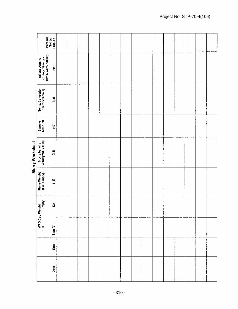
Project No. STP-70-4(106)
- 310 -

Project No. STP-70-4(106)
- 311 -
PORTLAND CEMENT CONCRETE (J-15-0216)
Paragraph 1. of Subsection 1002.02 in the Standard Specifications is amended to include the following: Concrete mixes will be in accordance of Table 1002.02. Paragraph 3. of Subsection 1002.02 is void and superseded by the following:
3. Type IP, IS and IT Interground/Blended cement shall be used for all classes of concrete except for pavement repair. Type IP, IS and IT Interground/Blended cement shall meet all requirements of ASTM C 595. Pavement repair shall include Type I/II Portland Cement for Class PR1 Concrete and Type III Portland Cement shall be used in Class PR3 Concrete.
Tables 1002.02 and 1002.03 in Subsection 1002.02 are void and superseded by the following:

Project No. STP-70-4(106)
- 312 -
ENGLISH TABLE 1002.02
Class of Concrete
(1)
Base Cement
Type
Total Cementitious
Materials Min. lb/cy
Total Aggregate
Air Content % Min.-Max.
(2)
Coarse Aggregate
(%)
Water/Cement Ratio Max.
(3)
Required Strength Min. psi
Min. lb/cy Max. lb/cy
47B**
IP/IS/IT*
564 2850 3150 6.5 - 9.0 - 0.45 3500
47B*** 564 2850 3150 6.0 - 8.5 - 0.45 3500
47BD 658 2500 3000 6.0 - 8.5 30+3 0.42 4000
47B-HE 752 2500 3000 6.0 - 8.5 30+3 0.40 3500
BX(4) 564 2850 3150 6.0 - 8.5 - 0.45 3500
47B-OL**** 564 2850 3200 5.0 - 7.0 30+3 0.36 4000
PR1 I/II 752 2500 2950 6.0 - 8.5 30+3 0.36 3500
PR3 III 799 2500 2950 6.0 - 8.5 30+3 0.45 3500
SF(5) I/II 589 2850 3200 6.0 - 8.5 50+3 0.36 4000
(1) Each class of concrete shall identify the minimum strength requirement, per plans and specifications. All classes of concrete shall be air-entrained and a water-reducing admixture shall be used per manufacture’s recommendations.
• Class R Combined Aggregate shall use a mid-range water reducer admixture. The dosage shall be at the manufacture’s recommendation and the Engineer may approve a low-range water reducer admixture.
(2) As determined by ASTM C 138 or ASTM C 231. FOR INFORMATION ONLY. The Contractor may develop a Quality Control Program to check the quantity of air content on any given project; such as,
checking the air content behind the paver. (3) The Contractor is responsible to adjust the water/cement ratio so that the concrete supplied achieves the required compressive strength
without exceeding the maximum water/cement ratio. The minimum water/cement ratio for any slip form concrete pavement is 0.38, unless the Contractor requests approval from the Engineer in writing to change the minimum water/cement ratio to 0.36.
(4) For temporary surfacing, Type I/II cement is allowed. (5) Minimum Portland Cement shall be 564 lbs/cyds and the total Silica Fume added shall be 25 lbs/cyds.
(*) Refer to Subsection 1004.02 for material characteristics. Lithium Nitrate may be used in place of Supplemental Cementitious Materials (SCMs), see Section 1007 of the Standard Specifications as modified in these Special Provisions. (**) For slip form applications. (***) For hand-pours and substructures applications. (****) When IP using Class N pozzolan, the maximum water/cement ratio is 0.41.
Project No. STP-70-4(106)
- 313 -
Table 1002.03 Table of Acceptable Concrete Class Substitutions Class Specified Acceptable Class for Substitution
BX 47B, 47BD or 47B-HE 47B 47BD or 47B-HE
Paragraphs 5., 6., 7., 8., 9. and 10. of Subsection 1002.02 are void and superseded by the following:
5. Class PR1 and PR3 Concrete:
a. The calcium chloride for use in PR concrete shall be either:
(1) A commercially prepared solution with a concentration of approximately 32 percent by weight.
(2) A Contractor prepared solution made by dissolving 4.5 pounds of
Grade 2 or 6.2 pounds of Grade 1 calcium chloride per gallon of water to provide a solution of approximately 32 percent by weight.
b. The 7.4 pounds of water in each gallon of solution shall be considered
part of the total water per batch of concrete.
c. The calcium chloride solution shall be added, just prior to placement, at a rate of 0.375 gallons/100 pounds of cement (1.4 lb. calcium chloride per 100 lb. cement).
d. Class A, Flaked or Pellet Calcium Chloride shall be added at a rate not to
exceed 2.0 percent of the weight of the cement for Grade 1, or 1.6 percent of the weight of the cement for Grade 2. Grade 1 Calcium Chloride purity is between 70 and 90 percent and Grade 2 Calcium Chloride is between 91 and 100 percent.
e. Where mixing trucks are used:
(1) For Class PR3 Concrete, calcium chloride shall be thoroughly
mixed into the concrete before placement. The minimum mixing time is 2 minutes.
(2) For Class PR1 Concrete, calcium chloride shall be added first and
then the concrete mixed at least 2 minutes or as required by manufacturer. Next, the Type F high range water-reducer admixture is added and the concrete is mixed an additional 5 minutes.
6. Class High Early (47B-HE) Concrete
a. High Early (47B-HE) concrete shall be cured as prescribed in
Subsection 603.03, Paragraph 7. The Contractor shall take necessary curing measures so the required strength is achieved.

Project No. STP-70-4(106)
- 314 -
b. High Early concrete shall achieve a compressive strength of 3,500 psi at 48 hours after placement.
c. The 48-hour compressive strengths shall be used to determine pay factor
deductions for high early concrete in accordance with Table 603.03.
d. A non-calcium chloride accelerator shall be used when the ambient temperature at the time of the placement of concrete is 70°F or less.
e. When requested by the Contractor, the maturity method, as provided in
NDR C 1074, may be used in lieu of the requirements of Subsection 603.03, Paragraphs 11.c. and d. to determine the strength of concrete pavement for the purpose of early opening to traffic and acceptance. Requests by the Contractor for use of the maturity method shall be on a project basis and shall be made in writing to the Engineer.
7. The yield of the concrete proportions shall be determined and adjusted by the
Producer. 8. All Classes of Concrete with the exception of PR1 and PR3 shall have a
Durability Factor not less than 70 and a mass loss not greater than five percent after 300 freeze/thaw cycles when tested in accordance with ASTM C 666. The freeze/thaw testing shall be conducted according to Procedure A.
Paragraphs 1. & 2. of Subsection 1002.03 are void and superseded by the following: 1. The Contractor shall identify the plant that will supply the concrete 14 days
before use and be entirely responsible for its calibration, batching of concrete, aggregate and sampling of cement per NDR Sampling Guide.
a. The Contractor shall be responsible for the following: 1) Batching concrete. 2) Contractor shall sample aggregate from the conveyor belt or
stockpile. Gradations from a split sample shall be tested in accordance to Section 1033 and reported to the Engineer at the frequency required by the Materials Sampling Guide.
i. Contractor shall retain possession of the split samples on-
site at the Contractor’s facility until such a time as determined by the Engineer.
a. At the pre-construction meeting: 1) Contractor shall determine the location of
testing and report the names of the technician performing the sampling and testing.
2) Engineer will notify the Contractor of the
retrieval of the split samples.

Project No. STP-70-4(106)
- 315 -
ii. The Contractor shall split the sample, place the
Department’s split sample into a cloth bag and immediately seal the split sample with the provided security seal. The cloth sample bag shall be supplied by the Department.
iii. The sampling splitting and placement of the security seal
of aggregate samples shall be witnessed by certified Department personnel.
iv. Contractor shall secure the split sample using a
consecutively numbered security seal of 75 pounds breaking strength provided by the Department. The Contractor shall use the consecutively numbered security seals to identify and track each Aggregate Class. Samples that are not consecutively numbered will be investigated for custody of the sample and the Engineer may cease production until it is determined what action will be required.
a. The Contractor shall report the security seal
tracking number with the split sample gradation. b. The following training shall be required for
personnel who oversee the batching of the concrete:
1) Concrete Technician Personnel i. Concrete Plant Technician 2) Portland Cement Sampler i. NDR Portland Cement Sampler 2. Portland Cement Concrete shall be supplied by certified Ready Mix Plants that
are in compliance with the requirements in the Quality Control Manual, Section 3, -- Certification of Ready Mixed Concrete Production Facilities published by the National Ready Mixed Concrete Association. Refer to NDR Material Sampling Guide for the policy on stationary and portable plants.
Paragraph 4. of Subsection 1002.03 is void and superseded by the following: 4. a. Mix times shall meet the requirements of ASTM C 94. Mixing time tests
shall be repeated whenever the concrete appearance indicates that mixing was inadequate.
b. Batch plants that are transporting the concrete in non-agitating trucks, the
mixing time will not be less than 60 seconds, and for agitating trucks, the mixing time will not be less than 45 seconds.

Project No. STP-70-4(106)
- 316 -
c. The Certification of stationary and portable ready mix plants will conform to the tests that are required in the NDR Materials Sampling Guide.
Paragraph 6. of Subsection 1002.03 is void and superseded by the following: 6. Batch tickets shall be prepared as prescribed in the National Ready Mixed
Concrete Association's Quality Control Manual. The Contractor shall keep all gradations and batch tickets until final acceptance by the Department. Projects that have less than 200 cubic yards of concrete placed will be allowed to have hand written tickets. For projects greater than 200 cubic yards, hand written tickets will be at the Engineer’s discretion. The concrete batch tickets shall show batch weights, aggregate moisture (shall be tested daily and moisture probes are allowed), admixtures used, water, and mix design calculations. A copy of the batch ticket shall be given to the Engineer upon delivery of concrete.
Paragraph 8. of Subsection 1002.03 is void and superseded by the following: 8. Coarse aggregate from a dry pit shall be uniformly saturated with water before it
is used. The wetting shall begin 24 hours prior to the concrete mixing to allow complete saturation.
Paragraph 13.a. of Subsection 1002.03 is void and superseded by the following: 13. a. The quantity of water shall be determined by the Contractor. The minimum
quantity of water should be used which will produce required workability. Any additional water used to rinse the charging hopper and fins after the batching of concrete is allowed. This water must be estimated and recorded on the batch ticket.
Subsection 1002.04 is void and superseded by the following: 1. Class 47B Concrete Mix Design Submittal: a. The Contractor shall submit the Concrete Mix Design Worksheet
consisting of design mix proportions, testing of mix design from a minimum of 4 cubic yards and aggregate data for 47B class of concrete being placed on the project.
(1) All testing must be performed by a qualified laboratory found on
the NDR’s Material and Research website, under the Nebraska Qualified Consultant & LPA Laboratories and submitted to the Engineer.
(2) The Concrete Mix Design shall be submitted to the Engineer
4 weeks prior to any concrete being placed on the project. (3) The Concrete Mix Design shall not be paid for directly by the
Department and shall be subsidiary to items which direct payment is made.

Project No. STP-70-4(106)
- 317 -
(4) Concrete shall not be placed on the project before the Concrete Mix Design Worksheet has been reviewed and approved by the Engineer.
b. The Contractor shall submit the Concrete Mix Design Worksheet to the
Engineer. Email submissions are preferred but will be accepted by fax or postal mail.
(1) Contractor’s Mix Design Worksheet can be found on the Materials
and Research website. The submitted Mix Design Worksheet shall include the following:
Contractor Name Project Number Date Location of ready mix or central mix plant Date submitted Signature of Contractor representative
(2) Material Source Information.
Cement Manufacturer Type of Interground/Blended Cement Type of Admixtures Aggregate Pit and Quarry location
(3) Specific Gravity of each individual aggregate source.
(4) Sand Equivalent for dry pit sand-gravel aggregate.
(5) Combined Aggregate percent passing as described on
Table 1033.03C.
(6) Contractor’s Target combined aggregate gradation percent passing.
(i) The Contractor’s required worksheet can be found on the
Materials and Research website.
(7) Testing of Mix Design:
The mix design shall show the weights of all ingredients including Interground/Blended cements, aggregates, water, admixtures types and water cement ratio.
Temperature of concrete at time of
sampling, ASTM C 1064.
The air content of plastic concrete, ASTM C 231.

Project No. STP-70-4(106)
- 318 -
Weight per cubic foot, Yield, ASTM C 138. The relative Yield shall be a minimum of 97%.
Compressive strength shall be performed with a minimum of three averaged specimens at 7-day and 28-day, ASTM C 39. The minimum 28-day compressive strength shall be 3500 psi.
(8) Traditional 47B Mix Design is defined as a 70 percent Class B
Aggregate and 30 percent Class E Aggregate may be exempt from the concrete testing described in Paragraph 1.(b)(7). All other requirements shall be included in the Concrete Mix Design Report.
c. The PCC Engineer will notify the Contractor of the mix design approval
for Class 47B Concrete. Approval of the mix design does not alleviate the Contractor of the responsibility of the in-place concrete. The Contractor may adjust admixtures, water cement ratio, vibrator frequency, etc., as needed in accordance to the specifications.
d. The Contractor shall submit a new concrete mix design worksheet
meeting the above requirements when a change occurs in the source, type, or proportions of cements or aggregates; unless otherwise approved by the Engineer.
2. The quantity of water to be used shall be determined by the Contractor. It shall
not be varied without the Engineer's consent. 3. If the concrete mixture is excessively wet causing segregation, excessive
bleeding, excessively dry or any other undesirable condition, the concrete shall be rejected. At the option of the Engineer, slump tests may be performed to determine the consistency.
4. Concrete which has developed initial set before it is consolidated and finished
shall be rejected. 5. a. If false set is encountered, the batching operation shall be stopped until
the problem is resolved. b. Each batch must be mixed or agitated for at least 3 additional minutes
after observing the false set and the concrete must be of satisfactory consistency.
6. Compressive strength tests shall be made in accordance with ASTM C 39. 7. Concrete shall be sampled as prescribed in the NDR Materials Sampling Guide.
Samples shall be taken at the point of placement, never before the discharge from the last conveyance.

Project No. STP-70-4(106)
- 319 -
8. Aggregate Acceptance, Verification, Sampling and Testing: a. The aggregate will be accepted based on the Contractor’s testing results
except as noted below. b. The aggregate verification sampling and testing by the Department will be
randomly selected and tested according to sublot sizes in Table 1002.05.
Table 1002.05
c. The results of Contractor split sample will be verified by the Department’s verification tests. Any samples outside of the tolerances as specified according to the Materials Sampling Guide, Section 28 under the Acceptable Tolerance Limits for Independent Assurance will result in an Independent Assurance (IA) review of testing and may result in the Department test results being applied.
d. On any given Lot, if the results of the gradation from the verification test
are within Department’s specification, the Contractor’s results will be used for the entire lot. On any given Lot, if the gradations results from the verification test are outside Department’s specification, further investigation will be initiated by the Engineer for that sublot. Any or all of the remaining Department sublot samples may be tested and the Department sublot test results may be applied to the respective sublot and the acceptance will apply.
e. When verification tests are within testing tolerance but results show a
consistent pattern of deviation from the split sample results, the Engineer will exercise one or more of the following:
- Cease production. - Request additional verification testing. - Initiate a complete IA review.
f. Independent Assurance (IA) Review of Testing: 1) The Contractor shall allow the Department personnel access to
the Contractors’ laboratory to conduct IA review of the technician testing procedures and apparatus. Any deficiencies discovered in the Contractor’s testing procedures will be reported to the Contractor and corrected by the Contractor.
2) During the IA review, the Department personnel and the
Contractor shall split a sample for the purpose of IA testing. The samples selected will be tested in the Department’s Branch Laboratory. Any IA test results found to be outside of defined
Aggregate Class Lot Sublot
E and F 3000 tons 1000 tons
A,B and C 6000 tons 2000 tons
R 6000 tons 2000 tons

Project No. STP-70-4(106)
- 320 -
testing tolerances as stated in Paragraph 8.c. of Subsection 1002.04 will be reported to the Contractor. The Contractor shall immediately correct any deficiencies found during the IA review.
3) If the project personnel and the Contractor cannot reach
agreement on the accuracy of the test results, the Department Central Laboratory will be asked to resolve the dispute, which will be final. All dispute resolutions will be in accordance with the Quality Assurance Program requirements in the NDR’s Materials Sampling Guide.
PORTLAND AND INTERGROUND/BLENDED CEMENT (J-15-0216)
Section 1004 in the Standard Specifications is void and superseded by the following: 1004.01 – Description 1. Portland cement is the binder in concrete, locking the aggregate into a solid structure. It
is manufactured from Lime, Silica, and Alumina (with a small amount of plaster of Gypsum).
2. Equivalent alkali referred to herein is hereby defined as the sum of the Sodium Oxide
(Na20) and the Potassium Oxide (K20) calculated as Equivalent Alkali Na20e = Na20+ 0.658 K20.
3. Interground and Blended cements consist of intimate and uniform intergrinding or
blending of Portland cement clinker, Slag cement, Pozzolan and/or Limestone. 1004.02 – Material Characteristics 1. Type I, Type II, Type I/II and Type III Portland cement shall conform to the requirements
in ASTM C 150 with the following additional requirements:
a. Portland cement shall not contain more than 0.60 percent equivalent alkali. 2. Interground and Blended Cement shall conform to the requirements in ASTM C 595 with
the following additional requirements: a. Interground/Blended cement (Type IP) (1) For Type IP(25) shall be composed of Class F fly ash or Class N
pozzolan replacement shall be 25% + 2%. (2) For Type IP(20) shall be composed of Class F fly ash or Class N
pozzolan replacement shall be 20% + 2%. b. Interground/Blended cement (Type IS)
Project No. STP-70-4(106)
- 321 -
(1) For Slag Cement, the maximum replacement shall be 35% +5 when incorporated into the final Interground/Blended cement.
c. Interground/Blended cement (Type IT)
(1) For SCMs, Slag cement and Limestone, the maximum replacement by weight shall be 40%. The manufacturer has a production tolerance of + 2% from the proposed replacement.
(2) For Limestone cement, the replacement range shall be from 5.1% to
10.0% when incorporated into the final Interground/Blended cement.
d. No additional SCMs, Slag cement and Limestone will be added at the batch plant.
1004.03 – Procedures 1. The Contractor shall provide adequate protection for the Portland and
Interground/Blended cement against dampness. a. Portland and Interground/Blended cement shall be hauled or stored in railroad
cars, dry bulk trailers or in suitable moisture-proof buildings. b. The use of tarpaulins for the protection of the Portland and Interground/Blended
cement against moisture will not be allowed. 2. No Portland and Interground/Blended cement which has become caked or lumpy shall
be used. 3. Portland and Interground/Blended cement which has been spilled shall not be used. 4. Accepted Portland and Interground/Blended cement which has been held in storage at
the concrete mix plant more than 90 days shall be retested. 5. Portland and Interground/Blended cement coming directly from the manufacturer shall
not be used until the temperature is 150°F or less. 6. Portland cement having false set when tested in accordance with in ASTM C 150 will not
be used. 1004.04 – Acceptance Requirements 1. For Department projects, Portland and Interground/Blended cements must be on the
NDR Approved Product List (APL). 2. The Contractor shall submit any new Portland and Interground/Blended cements to the
Engineer to be approved for the APL with the following: a. Material source information: 1) Mill Location

Project No. STP-70-4(106)
- 322 -
2) Type of Portland and Interground/Blended cements 3) Grinding Period 4) Associated Manufacture Product Name 5) Provide source and type of each SCMs and/or Slag Cement used for final
product. (i) The Department will allow the use of ASTM C 1697. a. When two or more SCMs and/or Slag Cement are
pre-blended, the Contractor shall report chemical composition analysis of the final blend.
b. The final blend shall be reported as per ASTM C 1697,
Paragraph 4. 6) Portland cement shall conform to ASTM C 150. 7) Interground/blended cements shall conform to ASTM C 595. 8) Provide total cementitious materials replacement per ASTM C 595. 9) Report test results per ASTM C 1567 at 28-days. 3. Alkali Silica Reaction Requirements and Testing: a. Interground/Blended cement shall be tested according to the provisions of
ASTM C 1567. (1) The mortar bars shall be composed of Type IP, IS or IT
Interground/blended cement and sand and gravel from an approved Platte River Valley-Saunders County source.
i. When Elkhorn River-Madison County source or an out of state
aggregate source is being used on a project, the Elkhorn River or an out of state aggregate source shall be used in lieu of the Platte River Valley-Saunders County source.
ii. When Contractor proposes a change of aggregate source, then
the new aggregate source shall be tested by ASTM C 1567. (2) The mortar bars for the ASTM C 1567 shall not exceed 0.10% expansion
at 28 days. 4. Portland and Interground/Blended cements will be placed on NDR’s APL based on the
conformance with the NDR’s Acceptance Policy Portland and Interground/Blended Cements.

Project No. STP-70-4(106)
- 323 -
1004.05 - Sampling and Testing Requirements 1. All Portland and Interground/Blended cements shall be sampled and tested at the rate
as described in the NDR’s Materials Sampling Guide. a. The Department will inform the Contractor when a sample is required. b. A sample shall be taken by a Contractor’s Certified Portland Cement Sampler
and must be under the supervision of Department certified personnel. c. The sample shall be taken at the plant from a bulk shipment of a rail car, dry bulk
trailer, batch plant silo or from the line between the bulk truck and the silo. Upon sampling, the Department will take immediate custody of the sample.
2. Noncompliant material shall be tested in accordance with ASTM C 1567 and in
accordance with Section 1004.04, Paragraph 3.a. (1). i. The mortar bars for the ASTM C 1567 shall not exceed 0.10% expansion at
28 days. ii. If the expansion is greater than 0.10% at 28 days, then the Interground/Blended
cement shall be subject to removal, 40% pay and/or removal from NDR’s APL in accordance with NDR’s Acceptance Policy on Portland and Interground/Blended Cements.
3. Noncompliant material from the mill, terminal or project will be temporarily removed from
the Approved Products List pending further investigation. 4. If the noncompliant Portland or Interground/Blended cement is removed from the
Approval Products List, all shipments from the supplier will be held until the investigation of the failing samples have been completed by the NDR Materials and Research Division.
WATER FOR CONCRETE (J-15-0214)
Section 1005 in the Standard Specifications is void and superseded by the following: 1005.01 – Description 1. Water shall be free from objectionable quantities of oil, acid, alkali, salt, organic matter,
or other deleterious materials and shall not be used until the source of supply has been approved.
2. Wash water from the mixer washout may be used only with the Engineer’s approval.
Use of wash water will be discontinued if undesirable reaction with admixtures or aggregates occurs.

Project No. STP-70-4(106)
- 324 -
1005.02 – Material Characteristics 1. Water which contains more than 0.25 percent total solids by weight shall not be used. 2. When required by the Engineer, the quality of mixing water shall be determined by
NDR C 114, NDR T 290, NDR D 512, NDR C 1602, ASTM C 31, ASTM C 109, ASTM C 191, and ASTM C 1603.
3. Upon written request by the concrete producer and approval by Materials and Research,
the concrete producer may utilize up to 10% wash water for batching all classes of concrete with the following conditions:
a. Wash water shall conform to the requirements in NDR’s Material Sampling Guide
under Policy for Certification of Ready Mix Plants. b. Wash water must be clarified wash water that has been passed through a settling
pond system. c. Wash water must be scalped off of a settling basin that has been undisturbed for
a minimum of 12 hours. d. Wash water must be metered into each load. e. Wash water quantities shall be shown on the batch ticket.
CALCIUM CHLORIDE (J-15-0214)
Section 1006 of the Standard Specifications is void and superseded by the following: 1006.01 – Description Calcium Chloride shall be Type S (Solid) or Type L (Liquid). Calcium Chloride can be used for; but not limited to, dust control and acceleration of the set of concrete. 1006.02 – Material Characteristics The requirements for calcium chloride shall be tested in accordance with ASTM D 98. 1006.03 – Acceptance Requirements Acceptance shall be based on requirements contained in the NDR Materials Sampling Guide.

Project No. STP-70-4(106)
- 325 -
SECTION 1007 -- CHEMICAL ADMIXTURES (J-15-0214)
Section 1007 in the Standard Specifications is void and superseded by the following: 1007.01 -- Description 1. Admixtures are materials added to Portland cement concrete to change characteristics
such as workability, strength, permeability, freezing point, and curing. 2. The Department's concrete admixture types are: a. Type A - Water-Reducing Admixture - An admixture that reduces the quantity of
mixing water required to produce concrete of a given slump. b. Type B - Retarding Admixture - An admixture that slows the setting of concrete. c. Type C - Accelerating Admixture - An admixture that speeds the setting and early
strength development of concrete. d. Type D - Water-Reducing and Retarding Admixture - An admixture that reduces
the quantity of mixing water required to produce concrete of a given slump and slows the setting of concrete.
e. Type E - Water-Reducing and Accelerating Admixture - An admixture that
reduces the quantity of mixing water required to produce concrete of a given slump and speeds the setting and early strength development of concrete.
f. Type F - Water-Reducing, High Range Admixture - An admixture that reduces
the quantity of mixing water required to produce concrete of a given slump by 12 percent or greater.
g. Type G - Water-Reducing, High Range and Retarding Admixture - An admixture
that reduces the quantity of mixing water required to produce concrete of a given slump by 12 percent or greater and slows the setting of concrete.
h. Air-Entraining - An admixture that encapsulates air in the concrete. i. Lithium Nitrate – An admixture used to control the Akali Silica Reaction (ASR) in
concrete. 1007.02 -- Material Characteristics 1. Type A through G admixtures shall meet the requirements in ASTM C 494. 2. Air-entraining admixtures shall meet the requirements in ASTM C 260. 3. Use of admixtures other than those cited may be requested by the Contractor. 4. Admixtures shall not contain more than 1 percent of chlorides calculated as calcium
chloride unless specified otherwise in the Specification.

Project No. STP-70-4(106)
- 326 -
5. Admixtures shall be used at the manufacturer's recommended dosage rates. 6. The air-entraining admixture characteristics shall produce concrete with satisfactory
workability and total air content as prescribed in Table 1002.02. 7. a. When using the Lithium Nitrate admixture, the Contractor shall submit to the
Engineer: (i) A five pound sample of Portland cement that will be used on the project. (ii) The Manufacturer’s method for determining the recommendation for the
required dose rate based on the equivalent alkali content. (iii) Water content of the Lithium Nitrate admixture solution. b. The Engineer will report the equivalent alkali content to the Contractor. The
Contractor shall use the reported equivalent alkali content to determine the required dose rate based on the manufacturer’s recommendation.
1007.03 -- Procedures 1. The process for adding admixtures to a ready mix truck on the project site involves
positioning the load of concrete up to the truck chute, stopping short of discharge. a. The admixture is then poured over the surface of the concrete and mixed for at
least 5 minutes. b. No more than 1.3 gallons of water shall be used to rinse the admixture from the
fins and top chute. This water must be shown on the proportioning report and shall not exceed the water cement ratio.
c. When Lithium Nitrate is used, the portion of the admixture that is water will be
shown on the proportioning report and shall not exceed the water cement ratio. d. The Contractor is responsible for the addition of the admixture. 2. a. If the air content is less than the minimum specified, addition of air-entraining
admixtures is allowed. b. The Contractor shall take measures based on manufacturer’s recommendations
that are within compliance of NDR Specifications, to bring the load of concrete into NDR prescribed limits according to Table 1002.02.
c. If the air content is then outside the limits in Table 1002.02, the load of concrete
shall be rejected. 1007.04 -- Acceptance Requirements 1. a. Approved chemical admixtures are shown on the NDR Approved Products List. b. Admixture approval shall be based upon annual certifications and certified test
results submitted to the NDR Materials and Research Division.

Project No. STP-70-4(106)
- 327 -
2. The admixture must be essentially identical in concentration, composition, and
performance to the admixture tested for certification. 3. Admixtures not identified on the NDR Approved Products List may be used under the
following conditions: a. A certificate of compliance and certified test results must be submitted to the
NDR Materials and Research Division and approval for use must be given by the NDR Materials and Research Division.
SILICA FUME (J-15-0307)
Paragraph 2 of Subsection 1009.03 in the Standard Specifications is void and superseded by the following:
2. Silica fume shall be protected from temperatures in excess of 90°F (32°C).
LIQUID MEMBRANE-FORMING COMPOUNDS FOR CURING CONCRETE (J-15-0307)
Subsection 1012.03 in the Standard Specifications is void and superseded by the following: 1012.03 – Acceptance Requirements 1. All curing compounds to be approved must be from the current calendar year with no
carry-over from the previous years. 2. Approved compounds are on the NDR Approved Products List. 3. Products not on the NDR Approved Products List shall be sampled and tested in
accordance with requirements of the NDR Materials Sampling Guide.
BITUMINOUS LIQUID COMPOUNDS FOR CURING CONCRETE (J-15-0515)
Section 1013 in the Standard Specifications is void and superseded by the following: 1013.01 – Description The compound shall consist essentially of an asphaltic base and shall be of a consistency suitable for spraying at temperatures existing at the time of construction operations. It shall form a continuous, uniform film. It shall be free of precipitated matter caused by conditions of storage or temperature. The compounds shall be relatively nontoxic.

Project No. STP-70-4(106)
- 328 -
1013.02 – Material Characteristics
a. When tested in accordance with AASHTO T 155, the loss of water shall not be more than 0.11 lb/ft2 (0.55 kg/m2) of surface area at 3 days, unless otherwise specified by the Engineer.
b. The Contractor has the option of using bituminous tack coat. The tack coat shall
conform to all requirements of Section 504.
c. The base material shall conform to Sections 1030, 1031 and 1032. 1013.03 – Acceptance Requirements Products shall be sampled and tested in accordance with requirements of the NDR Materials Sampling Guide.
JOINT AND CRACK SEALING FILLER (J-15-0813)
Section 1014 in the Standard Specifications is void and superseded by the following: 1014.01 – Description Joint sealing filler shall be either a cold applied silicone product or an asphalt product (hot pour) conforming to the requirements of this Section. The type of joint filler to be used shall be as specified in the plans or special provisions. If not specified, any of the joint sealing fillers in this Section may be used. Crack sealing filler shall be a hot pour sealer conforming to the requirements of this Section. 1014.02 -- Material Characteristics 1. NE-3405 and NE-3405LM (hot pour) a. NE-3405 joint and crack sealer shall conform to the requirements of ASTM
D6690, Type II. The material shall conform to the requirements of Table 1 with the following exception:
(i) The test of Bond, non-immersed, ASTM D5329, 3 specimens through
3 cycles shall be run at 0F (-18oC), 100% extension. b. NE-3405LM (Low Modulus) joint and crack sealer shall conform to the
requirements of ASTM D6690, Type IV. The material shall conform to the requirements of Table 1.
c. The test of Bond, non-immersed, ASTM-D5329, will be tested on concrete blocks
that will be constructed by the NDR Concrete Laboratory. The concrete blocks will be made of a 47B concrete mixture as prescribed in Section 1002 in the NDR Standard Specifications. The design is amended so that no fly ash is used in the mixture. All other specifications for Portland Cement Concrete apply.

Project No. STP-70-4(106)
- 329 -
d. Sample conditioning, preparation and heating shall be in accordance with ASTM D 5167 with the following exceptions:
(i) The following sentence of Section 8.1.2, “Also, if present, remove
container liner by cutting it away”, is void and superseded by the following:
“Also, if present, as much of the polyethylene bag as possible,
shall be removed by cutting it away. Wholly-meltable type container in contact with the sample section shall be left in place.”
(ii) The last sentence of Section 8.1.2 “Solid Materials” is void and
superseded by the following: The entire vertical section which has been cut, shall be placed into
the pot for melting. (iii) The Section of 8.2.2.1 “Solid Materials” is void. (iv) The Section of 8.2.3 is void and superseded by the following: After the solid segment is added to the melter, the material shall
be allowed to minimally melt to a uniform viscous state suitable for the installation of the stirrer or paddle. The sample shall then be stirred for one full hour. The oil bath temperature shall be regulated to bring the material to the maximum heating temperature within the one hour of stirring.
(v) The Section of 8.2.4.1 is void and superseded by the following:
During the one full hour of stirring, check the temperature of the material at maximum 15 minute intervals using a Type K thermocouple with the calibration verified in accordance with Section 6.1.7 to ensure conformance with specified temperature requirements. Stop the mechanical stirrer when measuring temperatures. If material temperatures ever exceed the maximum heating temperature, or ever drop below the minimum application temperature after the maximum heating temperature was reached, discard the sample and re-do the heating. Maintain appropriate records of times and temperatures to verify conformance with specification requirements.
(vi) The Section of 8.2.4.2 is void. e. ASTM D 5329 shall include the following changes: (i) Sections 6.4 and 12.4 “Specimen Preparation” shall have the reference of
“177 ml (6 oz.)” replaced with “3 oz.”

Project No. STP-70-4(106)
- 330 -
(ii) Section 6 “Cone Penetration, Non-Immersed” shall be superseded with the following exceptions:
1. Section 6.5 “Procedure” is void and superseded by the following:
Place the specimen in a water bath maintained at 77 +/- 0.2°F (25 +/- 0.1C) for two hours immediately before testing. Remove the specimen from the bath and dry the surface by shaking gently to remove free water from the surface of the specimen. Using the apparatus described in Section 6.3, make one determination at or near the center of the specimen. Take care to ensure the cone point is placed on a point in the specimen that is representative of the material itself, and is free of dust, water, bubbles, or other foreign material.
2. Section 6.6 “Report” is void and superseded by the following: Record the value as penetration of the specimen in dmm
units. (iii) Section 12 “Resilience” shall be superseded with the following
exceptions: 1. Section 12.5 “Procedure”, void the sentence “Make determinations
at three points equally spaced from each other and less than 13mm (½ inch) from the container rim” and supersede with the sentence “Make one determination at or near the center of the tin.”
2. Section 12.6 “Report” is void. 2. Silicone Joint Sealer (cold applied) a. Silicone joint sealers may be either self-leveling or non-sag and shall meet the
requirements in Table 1014.01.
Table 1014.01 Silicone Joint Sealer Requirement
Property Requirement Test As supplied: Specific Gravity Work Time, minimum Tack-Free, at 25°C Cure Time, at 25°C, maximum Full Adhesion, maximum
1.010-1.515 10 minutes 20-360 minutes 14 days 21 days
ASTM D792
As cured, at 25°C + 1.5 Elongation, minimum Durometer Non-Sag, Shore A Self-Leveling, Shore 00, minimum Joint Movement Capacity Tensile Stress, at 150% Elongation
800% 10-25 40 +100% to -50% 45 psi
ASTM D412 ASTM D2240 ASTM D2240 ASTM C719 ASTM D412

Project No. STP-70-4(106)
- 331 -
1014.03 -- Packaging 1. NE-3405 and NE-3405LM a. The joint and crack sealer can be packaged in either cardboard box of wholly-
meltable type containers. (i) Cardboard box containers shall be manufactured from double wall kraft
board producing a minimum bursting test certification of 350 PSI (241 N/cm2) and using water-resistant adhesives. The use of metal staples or fasteners of any kind will be prohibited for closing the lids of the boxes. Tape or other like material is acceptable.
a. The joint and crack sealer shall be in meltable [300°F (149C)]
polyethylene bag(s). (ii) Wholly-meltable type containers, and any of their components, shall be
fully meltable and integrational with the joint and crack sealer by the time the manufacturer’s minimum application temperature is reached.
a. The wholly-melted and integrated container must not adversely
affect the test specifications of the joint and crack sealer. 2. Silicone Joint Sealer
a. Each container shall include information regarding manufacturer and product name.
1014.04 -- Acceptance Requirements
1. NE-3405 and NE-3405LM
a. Acceptance of the manufactured material is based on pre-approval by either on or off-site sampling. Acceptable hot pour sealant lots are listed on the NDR Approved Products List.
(i) NDR on-site field sampling shall be in accordance with the NDR Materials
Sampling Guide. (ii) Off-site (Proxy) sampling shall be in accordance with ASTM D 6690. 1. Proxy sampling shall be overseen by an outside party approved
by the NDR, preferably another DOT Agency. Proxy samples shall include a manufacturer’s Certificate of Compliance. Proxy samples shall also include a dated signature of origin by the Representative that is not affiliated with the manufacturer, and can either be on the Certificate of Compliance, or separate letter.
2. For convenience in both sampling and shipping samples, sample
containers smaller than a manufacturer’s usual production containers are allowed, as long as the sample is 1500 grams min.

Project No. STP-70-4(106)
- 332 -
3. Samples shall be sent to the NDR Bituminous Laboratory, or
alternatively, sent to an NDR-approved independent laboratory for testing which will be at no cost to the Department. If a NDR-approved independent laboratory will be used for testing purposes, the NDR Bituminous Laboratory must be notified so that NDR concrete blocks for Bond testing can be sent to it.
2. Silicone Joint Sealer
a. Acceptance of applied silicone joint sealers shall be in accordance with the NDR Materials Sampling Guide.
b. Acceptable silicone joint sealer manufacturer products are listed on the NDR
Approved Products List. (i) For products that are not listed, approval may be based upon test results
from an independent laboratory submitted to the NDR Concrete Materials Section by the manufacturer, and testing by the NDR. Approval must be made prior to product use.
EPOXY COMPOUNDS AND ADHESIVES (J-15-0308)
Section 1018 in the Standard Specifications is void and superseded by the following: 1018.01 – Description This specification provides requirements for two-component, epoxy-resin bonding systems for use in non-load bearing applications and resin adhesives for application to Portland cement concrete. 1018.02 – Material Characteristics 1. Epoxy-resin bonding systems shall conform to the requirements of ASTM C 881.
Approved systems are shown on the NDR Approved Products List. 2. The classification of Epoxy-Resin Bonding Systems is as follows: a. Type I For use in non-load bearing applications for bonding hardened
concrete and other material to hardened concrete. Type II For use in non-load bearing applications for bonding freshly mixed
concrete to hardened concrete. Type III For use in bonding skid resistant materials to hardened concrete,
and as a binder in epoxy mortars or epoxy concretes. b. Grade 1 Low viscosity. Grade 2 Medium viscosity.

Project No. STP-70-4(106)
- 333 -
Grade 3 Non-sagging consistency. c. Class A For use below 40°F (4°C); the lowest allowable temperature to be
defined by the manufacturer of the product. Class B For use between 40°F and 60°F (4°C and 15°C). Class C For use above 60°F (15°C); the highest allowable temperature to
be defined by the manufacturer of the product. Class D For use between 40°F and 65°F (4°C and 18° C). Class E For use between 60°F and 80°F (15°C and 26°C). Class F For use between 75°F and 90°F (24°C and 32°C). 1018.03 – Procedures 1. The compounds shall be of the type and grade specified in the plans or as directed by
the Engineer. 2. The class of the compounds shall be selected for use according to climatic conditions at
the time of application. 3. All bonding surfaces shall be clean and free of all oil, dirt, grease, or any other materials
which would prevent bonding. 4. Mixing and application shall be in strict accordance with the manufacturer’s instructions. 1018.04 – Acceptance Requirements 1. Epoxy-resin bonding systems and resin adhesives approved for use are shown on the
NDR Approved Products List. 2. Epoxy-resin bonding systems that are not on the NDR Approved Products List may be
accepted based on a manufacturer’s certificate of compliance.
DEFORMED METAL CENTER JOINT AND METAL KEYWAY (J-15-0307)
Paragraph 1 a. of Subsection 1027.01 in the Standard Specifications is void and superseded by the following:
a. Metal Center Joint:
Metal center joint sections shall be manufactured from sheets no less than 18 gauge [0.05 inch (1.3 mm)] thick and shall be of the size and trapezoidal shape shown in the plans. The sections shall be punched along the centerline of the narrow face of the trapezoid to admit the tie bars required by the plans and

Project No. STP-70-4(106)
- 334 -
also at intervals of not greater than 2 feet (600 mm) to receive pins that are driven vertically into the subgrade to support the metal center joint.
AGGREGATES (J-15-0616)
Subsection 1033.01 is amended to include the following paragraphs and Subsection 1033.02, Paragraphs 1., 2. and 3. of the Standard Specifications are void and superseded by the following: 1033.01 – Description This combined aggregate gradation using Class R aggregate is to optimize aggregate blends utilizing more locally available materials. Achieving a uniform gradation for Class R may require the use of two or more different aggregates. It is the responsibility of the contractor to consider additional material characteristics; such as, but not limited to particle shape, cubicity, angularity, etc., when designing a mix. 1033.02 -- Material Characteristics 1. Sampling and Testing Procedures:
All materials shall be sampled and tested in accordance with Table 1033.01. All material source locations and quarries must be approved by the Department for prior to use.
Table 1033.01
Sampling and Testing Procedures Procedure Method Sampling NDR T 2 Sieve Analysis NDR T 27 Clay Lumps, Shale, and Soft Particles NDR T 504 Abrasion AASHTO T 96 Freeze and Thaw Soundness NDR T 103 Specific Gravity and Absorption (course aggregate)
AASHTO T 85
Specific Gravity and Absorption (fine aggregate)
AASHTO T 84
Total Evaporable Moisture Content of Aggregates by Drying Plastic Fines in Graded Aggregates and Soils by Use of the Sand Equivalent Test
AASTHO T 255 AASTHO T 176
Sodium Sulfate Soundness AASHTO T 104 Calcium Carbonate NDR C 25 Organic Impurities AASHTO T 21 Mortar-Making Properties AASHTO T 71 Reducing Field Samples of Aggregate to Testing Size
AASHTO T 248
Lightweight Pieces in Aggregates NDR T 113
Project No. STP-70-4(106)
- 335 -
2. General Aggregate Properties: a. Aggregates shall be free from injurious quantities of dust, soft or flaky particles,
loams, alkali, organic matter, paper, wood or other deleterious matter as determined by the Engineer.
b. Dolomite as herein defined is a magnesium limestone containing calcium
carbonate and magnesium carbonate in approximately a 4 to 3 ratio. c. The calcium carbonate content of limestone shall be at least 80 percent
(computed as CaCO3 from the value determined for CaO). d. Fine Sand shall have at least 95 percent of its particles pass the No. 10 (2.0 mm)
sieve and no more than 25 percent pass the No. 200 (75 µm) sieve. This definition applies to sodium sulfate soundness test.
e. Once an aggregate’s soundness and abrasion quality has been determined,
additional quality testing for soundness and abrasion loss will be at the Engineer’s discretion.
f. All aggregates or combine aggregates that have been washed or coming from a
wet pit shall be stockpiled for a minimum of 48 hours before being introduced into concrete.
3. Portland Cement Concrete Aggregates:
a. Fine Aggregate:
(1) Aggregate shall be washed and composed of clean, hard, durable and uncoated particles.
(2) Aggregates produced from wet pits by pumping must be adequately
washed by means approved by the Department. (3) Aggregates from dry pits shall be adequately washed by means approved
by the Department and have a Sand Equivalent value not less than 90 in accordance with AASTHO T 176.
(i) If the Sand Equivalent is less than 90, the Engineer may elect to stop aggregate production until such a time ASTM C 109 has been completed. The aggregate, when subjected to the test for mortar-making properties, shall produce a mortar having a compressive strength at the age of 7 days equal to or greater than that developed by mortar of the same proportions and consistency made of the same cement and aggregate after the aggregate has been washed to a sand equivalent greater than 90. Materials failing to produce equal or greater strength shall be unacceptable.
(4) Aggregate for concrete shall have a soundness loss of not more than
10% by weight at the end of 5 cycles using Sodium Sulfate Soundness test AASHTO T 104.

Project No. STP-70-4(106)
- 336 -
(5) The weight of the aggregate shall not contain more than 0.5% clay lumps.
(6) Aggregate subjected to the colorimetric test for organic impurities which produces a color darker than the standard shall be further tested for its mortar-making properties in accordance with AASHTO T 71. The Engineer may elect to stop aggregate production until such a time AASHTO T 71 testing has been completed.
(i) Aggregate, when subjected to the test for mortar-making properties, shall produce a mortar having a compressive strength at the age of 7 days equal to or greater than that developed by mortar of the same proportions and consistency made of the same cement and aggregate after the aggregate has been treated in a 3% solution of sodium hydroxide. Materials failing to produce equal or greater strength shall be unacceptable, except when determined to be acceptable under the provisions of Subsection 105.03.
(7) Aggregate shall meet the requirement in Tables 1033.02A, 1033.02B and
1033.03C. (8) Lightweight pieces (measured by percent by volume values) shall not
exceed 3.5%. For Class R aggregate, fine aggregate is defined as any material passing a No. 4 sieve.
Table 1033.02A
Percentage
Percent Passing 1½” 1” ¾” ½” 3/8 No.4 No.10 No.20 No.30 No.200
AGGREGATE SPECIFICATION RANGE
Class A Max Min
-- -- -- -- 100 100 92
90 64
-- 40 10
3 0
Class B Max Min
-- 100 -- -- -- 97 77
70 50
-- 40 16
3 0
Class C Max Min -- 100 -- -- --
88 44
50 24
-- 20 4
3 0
Table 1033.02B
Aggregate Classes and Uses Aggregate Class Concrete Description A Overlay Concrete SF B 47BD, 47B-HE, 47B-OL, PR 1 and PR 3 C BX
b. Coarse Aggregate: (1) Aggregate shall consist of Limestone, Quartzite, Dolomite, Gravel and
Granite composed of clean, hard, durable, and uncoated particles. (2) The percent of clay lumps, shale, soft particles or lightweight pieces shall
not exceed the following amounts:
Clay Lumps ......................... 0.5% Shale ................................... 1.0% Soft Particles ....................... 3.5% Lightweight Pieces .............. 3.5%

Project No. STP-70-4(106)
- 337 -
(3) Any combination of clay lumps, shale and soft particles (all percent by weight values), plus the lightweight pieces (a percent by volume value) shall not exceed 3.5%. For Class R aggregate, coarse aggregate is defined as any materials retained on a No. 4 sieve.
(4) Aggregate for concrete shall be free of coatings that will inhibit bond and
free of injurious quantities of loam, alkali, organic matter, thin or laminated pieces, chert, or other deleterious substances as determined by the Engineer.
(5) Aggregate for concrete shall not have a soundness loss greater than
8.0% by weight at the completion of 16 cycles of alternate freezing and thawing.
(6) Aggregates for concrete shall have a Los Angeles Abrasion loss
percentage of not more than 40. (7) All fractions passing the No.4 sieve shall meet quality requirement of
soundness loss of not more than 10% by weight at the end of 5 cycles using sodium sulfate solution.
(8) The coarse aggregate shall be tested according to ASTM C 1260. (a) The mortar bars for the ASTM C 1260 shall not exceed 0.10%
expansion at 28 days.
(i) If the proposed coarse aggregate exceeds 0.10% expansion at 28 days, the aggregate proportions used on the project shall be tested in accordance to ASTM C 1567.
a. The ASTM C 1567 mortar bars shall be composed of Interground/blended cement being used on the project.
b. If the expansion is greater than 0.10%, the coarse aggregate shall not be used.
(9) Aggregate shall meet the requirements in Tables 1033.03A, B, and C.
Table 1033.03A
Percent Percent Passing
1 ½” 1” ¾” ½” 3/8 No.4 No.10 No.20 No.30 No.200
AGGREGATE SPECIFICATION RANGE
Class E Max Min
100 100 92
90 66
-- 45 15
12 0
-- *4 0
-- 3 0
Class F Max Min
-- -- 100 100 96
90 40
30 4
8 0
-- -- 3 0
*If the No. 200 sieve is less than 1.5% passing the No.20 sieve could be increased to maximum of 6% passing.

Project No. STP-70-4(106)
- 338 -
Table 1033.03B Aggregate Classes and Uses
Aggregate Class
Concrete Description
E 47BD, 47B-HE, PR 1 and PR 3
F 47B-OL, Overlay Concrete SF c. Combined Aggregates: (1) The Contractor shall design and meet the specification requirements. It is
the Contractor’s responsibility to provide desirable mix properties; such as, but not limited to, workability, resistance to segregation, stable air void system, good finishing properties and good consolidation properties.
(2) The combined blended aggregate shall meet the requirement in
Table 1033.03C and 1033.03D.
Table 1033.03C
* Refer to Subsection 1002.04, Paragraph 1.b.(8) for the traditional 47B Mix Design
Table 1033.03D Aggregate Classes and Uses
Aggregate Class Concrete Description R 47B
d. Aggregate Production and Testing: (1) Any change greater than 3% in the original verified constituent
percentage of the combined aggregates gradation will be considered non-compliant. Any change of the combined gradation targets must remain within the Combined Aggregate Gradation Limits in Table 1033.03C. The Contractor shall resubmit a new mix design if the material is deemed non-compliant in accordance with Subsection 1002.04, Paragraph 1.
(2) The blended gradation tolerance ranges from the approved mix design
are established in Table 1033.03E. (i) The Contractor shall assume the responsibility to cease
operations when the specifications are not met. Production shall not be started again without the approval of the Engineer.
Table 1033.03E Blended Aggregate Production Tolerances Sieve Size Tolerances No. 4 or greater + 5% No. 10 to No. 30 + 4% No. 50 + 3% Minus No. 200 + 1%
*Class R - Combined Aggregate Gradation Limits (Percent Passing) Sieve Size 1 ½ inch 1 inch 3/4 inch No.4 No.10 No.30 No. 50 No.200 Max 100 100 98.0 70.0 50.0 30.0 12.0 3.0 Min - 92.0 85.0 45.0 31.0 8.0 2.0 0

Project No. STP-70-4(106)
- 339 -
(3) Coarse aggregate from a dry pit shall be uniformly saturated with water before it is used. The wetting shall begin 24 hours before concrete mixing to allow complete saturation.
DOWEL BARS (J-15-0812)
Paragraph 1.c. of Subsection 1022.01 in the Standard Specifications is void and superseded by the following: 1. c. Both Type A and Type B coated dowel bars shall be coated with a bond breaker
shown on the NDR Approved Products List, dipped in asphalt or paraffin, or greased in accordance with the specified requirements as shown in the Standard Plans.
EPOXY COATED REINFORCING STEEL (J-15-0509)
Paragraph 5. of Subsection 1021.03 in the Standard Specifications is void and superseded by the following: 5. In order to protect the coated reinforcement from damage, the Contractor shall
use padded or nonmetallic slings and padded straps. Bundled bars shall be handled in a manner which will prevent excessive sagging of bars which will damage the coating. If circumstances require storing coated steel reinforcing bars outdoors for more than two months, protective storage measures shall be implemented to protect the material from sunlight, salt spray and weather exposure. Coated steel reinforcing bars, whether individual bars or bundles of bars, or both, shall be covered with opaque polyethylene sheeting or other suitable opaque protective material. For stacked bundles, the protective covering shall be draped around the perimeter of the stack. The covering shall be secured adequately, and allow for air circulation around the bars to minimize condensation under the covering. Coated steel reinforcing bars, whether individual bars or bundles of bars, or both, shall be stored off the ground on protective cribbing. The bundled bars shall not be dropped or dragged. If, in the opinion of the Engineer, the coated bars have been extensively damaged, the material will be rejected. The Contractor may propose, for the approval of the Engineer, alternate precautionary measures.
REINFORCED CONCRETE PIPE, MANHOLE RISERS, AND FLARED END SECTIONS
(J-21-0108) The AASHTO reference made in paragraphs 4.a. and 4.b. of Subsection 1037.02 in the Standard Specifications is amended to read AASHTO M 170 / M 170M-95.

Project No. STP-70-4(106)
- 340 -
The AASHTO reference made in paragraph 5. of Subsection 1037.02 is amended to read AASHTO M 206 / M 206M-95. The AASHTO reference made in paragraph 6. of Subsection 1037.02 is amended to read AASHTO M 207 / M 207M-95. Paragraph 8. of Subsection 1037.02 is void and superseded by the following:
8. Concrete flared-end sections shall be of the design shown in the plans and in conformance with the applicable requirements of AASHTO M 170 / M 170M-95, Class II pipe, AASHTO M 206 / M 206M-95, Class A-II pipe, or AASHTO M 207 / M 207M-95, Class HE-II pipe for the diameter of pipe on which it is to be installed.
ASPHALTIC CONCRETE TYPE SLX (J-29-0414)
Asphaltic Concrete, Type SLX shall meet all of the requirements of Asphaltic Concrete, Type SPR, listed in Section 1028 and these Special Provisions, with the following exceptions: 1. Material Characteristics:
a. The type of PG Binder used shall be PG Binder 64-34 with 0.7% of an approved amine-based WMA additive.
b. Reclaimed Asphalt Pavement (RAP) will be added to the mix at a minimum of
20% and a maximum of 35%. The RAP must be fractionated/processed prior to use, to a sizing such that the combined hot mix meets the required gradation. The mat cannot exhibit any visual defects or cold spots from RAP conglomeration.
c. The mix shall contain a minimum of 20% Crushed Rock Chips (with a minimum
of 45% retained on the #4 sieve and a maximum of 5% passing the #200 sieve).
d. The Asphaltic Concrete shall have a minimum Fine Aggregate Angularity (FAA) of 43.0 on the combined aggregate blend. There is no requirement for Coarse Aggregate Angularity (CAA).

Project No. STP-70-4(106)
- 341 -
e. Asphaltic Concrete Type SLX shall use the gradation band listed below.
Gradation Control Points for Type SLX
Control Points
(percent passing) English Sieve
(Metric) Minimum Maximum
1/2 inch (12.5 mm) 98.0 100.0 3/8 inch (9.5 mm) 93.0 100.0 No. 4 (4.75 mm) 70.0 87.0 No. 8 (2.36 mm) 45.0 65.0 No. 16 (1.18 mm) 25.0 41.0 No. 30 (600 µm) 15.0 31.0 No. 50 (300 µm) 10.0 21.0 No. 100 (150 µm) --- ---
*No. 200 (75 µm) 4.0 10.0 * Dust to binder ratio is the ratio of the percentage by weight of aggregate finer
than the No. 200 (75 µm) sieve to the asphalt content expressed as a percent by weight of total mix. The dust to binder ratio shall be between 0.70 and 1.70.
2. Design Criteria:
a. The optimum binder content shall be the binder content that produces 2.0 to 4.0 percent air voids at 50 gyrations, with a minimum content of 5.3%.
b. The Voids in the Mineral Aggregate (VMA) shall be a minimum of 16% ± 1% (mix
design only). 3. Placing and Finishing:
a. Asphaltic Concrete shall be placed only when the ambient temperature is at least 40°F (4°C) and rising.
b. The asphaltic concrete temperature shall be 285° F (154°C) or above measured
in the truck just prior to placement. Exceptions to this requirement are that the PG Binder Supplier recommended maximum temperature requirement shall not be exceeded.
c. The Contractor will use steel wheel compactors only. Rubber tire rollers will not
be allowed. 4. Asphaltic Concrete Density:
Regardless of layer thickness, Asphaltic Concrete Type SLX will be monitored for density.
An initial rolling pattern test strip shall be completed to determine the rolling pattern that
will target a minimum of 92.5% density. The Contractor shall monitor the density through a combination of rolling pattern and field testing as deemed necessary by the Engineer.

Project No. STP-70-4(106)
- 342 -
Method of Measurement: For each lot of Asphaltic Concrete Type SLX, the asphaltic concrete shall be paid by the contract unit price for the item "Asphaltic Concrete, Type SLX". The asphaltic concrete unit price is a product of all applicable pay factors excluding density and CAA. Basis of Payment: Paragraphs 2.a., 2.b.(1), 2.b.(2) and 2.b.(3) of Subsection 503.06 are void and superseded by the following: Asphaltic Concrete Type SLX shall be paid per ton (Mg) for the item "Asphaltic Concrete
Type SLX".
SECTION 1038 -- PLASTIC PIPE (J-30-1014)
Section 1038 in the Standard Specifications is void and superseded by the following: 1038.01 – Description High density polyethylene (HDPE), polyvinyl chloride (PVC), and other NDR approved plastic pipes are authorized for use as stipulated in the contract documents. 1038.02 -- Material Characteristics 1. High density polyethylene (HDPE) pipes and fittings shall conform to the following
Specification requirements for the size required:
Table 1038.01 Polyethylene Pipe
English Size (Metric)
Specification Description
15 to 36 in (375 to 900 mm)
AASHTO M 294 Corrugated Polyethylene Pipe, Type C (Cell Class 335420C)
15 to 60 in (375 to 1500 mm)
AASHTO M 294 Corrugated Polyethylene Pipe, Type S (Cell Class 335420C)
15 to 60 in (375 to 1500 mm)
ASTM F 894 Profile Wall, OP, RSC 160 (Cell Class 335434C)
15 to 60 in (375 to 1500 mm)
ASTM F 2562 Steel Reinforced Thermoplastic Ribbed Pipe (Cell Class 345464C)
2. Polyvinyl Chloride (PVC) [Cell Classification 12454C or 12364C (as determined by
ASTM D-1784) if applicable] pipe and fittings shall conform to the following Specification requirements for the size required:

Project No. STP-70-4(106)
- 343 -
Table 1038.02 Polyvinyl Chloride Pipe
English Size (Metric)
Specification Description
18 to 48 in (450 to 1200 mm)
ASTM F 679 Gravity Sewer Pipe & Fittings
15 to 48 in (375 to 1200 mm)
ASTM F 794 Profile Gravity Sewer Pipe & Fittings, DWCP, OP, Series 46
15 to 48 in (375 to 1200 mm)
ASTM F 949 Corrugated Sewer Pipe w/smooth Interior with Fittings
15 in (375 mm) ASTM D 2680 Composite Sewer Pipe
15 in (375 mm) ASTM D 3034 Type PSM Sewer Pipe & Fittings, SDR 35
3. Plastic pipe for underdrains shall conform to the requirements of AASHTO M 252,
ASTM F 405, ASTM F 794 or ASTM F 949 for perforated or non-perforated pipe. Perforations for ASTM F 794 PVC pipe shall be slotted as per ASTM F 949.
4. Metal flared-end sections shall conform to the requirements in Section 1036. 5. A 10 foot (3 m) sample of each size and type of plastic pipe shall be sent to the
NDR Materials and Tests Laboratory in Lincoln for testing, before being incorporated into the project.
1038.03 -- Acceptance Requirements Plastic pipe will be accepted based on the requirements of this Section and sampling and testing requirements in accordance with the NDR Materials Sampling Guide.
ASPHALTIC CONCRETE TYPE SRM (J-31-0315)
Asphaltic Concrete, Type SRM shall meet all of the requirements of Asphaltic Concrete, Type SPR, listed in Section 1028 and these Special Provisions, with the following exceptions: 1. Material Characteristics:
a. The type of PG Binder used shall be PG Binder 58-34 with 0.9% of an approved amine-based WMA additive.
b. Reclaimed Asphalt Pavement (RAP) will be added to the mix at a minimum of
35% and a maximum of 65%.
c. The mix shall contain a minimum of 10% Crushed Rock (with a maximum of 20% passing the #4 sieve).
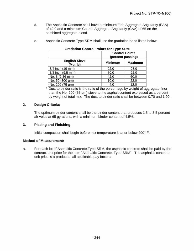
Project No. STP-70-4(106)
- 344 -
d. The Asphaltic Concrete shall have a minimum Fine Aggregate Angularity (FAA) of 42.0 and a minimum Coarse Aggregate Angularity (CAA) of 65 on the combined aggregate blend.
e. Asphaltic Concrete Type SRM shall use the gradation band listed below.
Gradation Control Points for Type SRM
Control Points
(percent passing) English Sieve
(Metric) Minimum Maximum
3/4 inch (19 mm) 92.0 98.0 3/8 inch (9.5 mm) 80.0 92.0 No. 8 (2.36 mm) 42.0 60.0 No. 50 (300 µm) 10.0 22.0
*No. 200 (75 µm) 4.0 12.0 * Dust to binder ratio is the ratio of the percentage by weight of aggregate finer
than the No. 200 (75 µm) sieve to the asphalt content expressed as a percent by weight of total mix. The dust to binder ratio shall be between 0.70 and 1.90.
2. Design Criteria:
The optimum binder content shall be the binder content that produces 1.5 to 3.5 percent air voids at 65 gyrations, with a minimum binder content of 4.5%.
3. Placing and Finishing:
Initial compaction shall begin before mix temperature is at or below 200° F. Method of Measurement: a. For each lot of Asphaltic Concrete Type SRM, the asphaltic concrete shall be paid by the
contract unit price for the item "Asphaltic Concrete, Type SRM". The asphaltic concrete unit price is a product of all applicable pay factors.

Project No. STP-70-4(106)
- 345 -
b. The pay factors for the single test air voids and moving average of four air voids pay factors will be determined in accordance with Table 1:
Table 1
Acceptance Schedule Air Voids - Ndes
Air voids test results for Asphaltic Concrete
Type SRM
Pay Factor
Moving average of
four Single test
0.0% to 0.4% 50% or Reject 50% or Reject 0.5% to 0.9% 50% or Reject 95% 1.0% to 1.4% 90% 95% 1.5% to 1.9% 100% 100% 2.0% to 3.0% 102% 104% 3.1% to 3.5% 100% 100% 3.6% to 4.0% 95% 95% 4.1% to 4.5% 90% 95% 4.6% to 5.0% 50% or Reject 90% 5.1% to 5.5% 50% or Reject 50% 5.6% and over 50% or Reject 50% or Reject
Basis of Payment: Paragraphs 2.a., 2.b.(1), 2.b.(2) and 2.b.(3) of Subsection 503.06 are void and superseded by the following: Asphaltic Concrete Type SRM shall be paid per ton (Mg) for the item "Asphaltic
Concrete Type SRM".
ROADWAY LIGHTING, SIGN LIGHTING, AND TRAFFIC SIGNALS (J-32-0416)
The first sentence of Paragraph 5.a. of Subsection 1073.02 in the Standard Specifications is void and superseded by the following:
a. Light poles, anchor bolts, and all accessory hardware shall be designed in accordance with AASHTO Standard Specifications for Structural Supports for Highway Signs, Luminaires, and Traffic Signals (Sixth Edition 2013, including all current Interim Revisions).
The first sentence of Paragraph 6.a. of Subsection 1073.02 is void and superseded by the following:
a. High mast towers, anchor bolts, and accessory hardware shall be designed in accordance with AASHTO Standard Specifications for Structural Supports for Highway Signs, Luminaires, and Traffic Signals (Sixth Edition 2013, including all current Interim Revisions).

Project No. STP-70-4(106)
- 346 -
PROPOSAL GUARANTY (A-40-0307)
As an evidence of good faith in submitting a bid for this work, the bidder shall indicate the type of bid bond applied to this project in accordance with the Proposal Guaranty Bid Bond Section of these Special Provisions.
* * * * * 400INFNOV16

Project No. STP-70-4(106)
- 347 -
INDEX ACCEPTANCE TESTING OF SOILS BY USE OF THE LIGHT WEIGHT DEFLECTOMETER
(LWD) SCOPE ...................................................................................................................... 139 ADJUST VALVE BOX TO GRADE .......................................................................................... 196 AGGREGATE FOUNDATION COURSE-D .............................................................................. 147 AGGREGATES ........................................................................................................................ 334 ASPHALT DENSITY GAUGE .................................................................................................. 297 ASPHALTIC CONCRETE ........................................................................................................ 186 ASPHALTIC CONCRETE LONGITUDINAL JOINT DENSITY TESTING ............................... 299 ASPHALTIC CONCRETE TYPE SLX ...................................................................................... 340 ASPHALTIC CONCRETE TYPE SRM ..................................................................................... 343 BACKFILLING CULVERTS ..................................................................................................... 230 BITUMINOUS FOUNDATION COURSE .................................................................................. 145 BITUMINOUS LIQUID COMPOUNDS FOR CURING CONCRETE ........................................ 327 BITUMINOUS PAVEMENT PATCHING .................................................................................. 191 BORROW, WASTE, STOCKPILE, AND PLANT SITE APPROVAL ....................................... 117 BRIDGE JOINT NOSING ......................................................................................................... 229 BRIDGE SHORING .................................................................................................................. 233 BUY AMERICA ......................................................................................................................... 116 CALCIUM CHLORIDE .............................................................................................................. 324 CERTIFICATION FOR FEDERAL-AID CONTRACTS ............................................................... 54 COLD WEATHER ASPHALTIC CONCRETE PLACEMENT ................................................... 186 CONCRETE BRIDGE FLOORS
(10-DAY WET CURE) ........................................................................................................... 203 CONCRETE CONSTRUCTION ........................................................................................ 202, 234 CONCRETE PAVEMENT ......................................................................................................... 197 CONCRETE PROTECTION BARRIERS ................................................................................. 172 CONSTRUCTION AND OBLITERATION OF TEMPORARY ROADS AND TEMPORARY
DRAINAGE ........................................................................................................................... 144 CONSTRUCTION DETAILS ..................................................................................................... 126 CONSTRUCTION METHODS .................................................................................................. 130 CONSTRUCTION STORMWATER MANAGEMENT CONTROL ............................................ 128 CONSTRUCTION SURVEYING ................................................................................................. 59 CONTRACT TIME ALLOWANCE ............................................................................................ 113 CONTRACTOR’S ACCESS BRIDGE ...................................................................................... 235 COVERCROP SEEDING .......................................................................................................... 241 CRUSHED CONCRETE FOUNDATION COURSE .................................................................. 148 CRUSHED ROCK BASE COURSE FOR CONCRETE BOX CULVERTS .............................. 234 CRUSHED ROCK EMBEDMENT ............................................................................................ 155 CULVERT MOUNTED GUARDRAIL POSTS .......................................................................... 263 DEBONDING PRESTRESSING STRANDS ............................................................................ 228 DEFORMED METAL CENTER JOINT AND METAL KEYWAY .............................................. 333 DISADVANTAGED BUSINESS ENTERPRISE (DBE) GOAL ................................................... 40
CERTIFICATION ..................................................................................................................... 46 DBE GOAL CREDIT ............................................................................................................... 42 DBE GOAL CREDIT TABLE .................................................................................................. 47 DESCRIPTIONS ..................................................................................................................... 44

Project No. STP-70-4(106)
- 348 -
SUBLETTING OR ASSIGNING OF CONTRACT ................................................................... 41 USE OF DISADVANTAGED BUSINESS ENTERPRISES ..................................................... 29
DISADVANTAGED BUSINESS ENTERPRISES ....................................................................... 28 (Prime Contractor Reporting of DBE Payments) ................................................................ 29
DOWEL BARS ......................................................................................................................... 339 DROP-OFF/COLD-MILLED TAPERED EDGE ........................................................................ 192 ELECTRONIC SHOP DRAWINGS .......................................................................................... 121 END ANCHORAGE ASSEMBLY ............................................................................................. 262 ENVIRONMENTAL COMMITMENT ........................................................................................... 60 ENVIRONMENTAL COMMITMENT DOCUMENT ................................................................... 131 ENVIRONMENTAL COMMITMENT ENFORCEMENT ............................................................ 134 EPOXY COATED REINFORCING STEEL ............................................................................... 339 EPOXY COMPOUNDS AND ADHESIVES .............................................................................. 332 EROSION CONTROL ............................................................................................................... 240 EXCAVATION AND EMBANKMENT ....................................................................................... 127 EXPANSION BEARINGS, PTFE TYPE ................................................................................... 229 EXPANSION DEVICE INSTALLATION ................................................................................... 233 FLOODPLAIN PERMIT ............................................................................................................ 107 FOUNDATION COURSE .......................................................................................................... 156 FOUNDATION COURSE 4” ..................................................................................................... 154 FUEL COST ADJUSTMENT PAYMENT ................................................................................. 126 FURNISHING AND PLANTING OF PLANT MATERIALS ....................................................... 251 GENERAL CONDITIONS ........................................................................................................... 28 GRANULAR SUBDRAINS ....................................................................................................... 260 GUARDRAIL END TREATMENT, TYPE II .............................................................................. 258 HYDRATED LIME FOR ASPHALT MIXTURES ...................................................................... 301 HYDRATED LIME SLURRY FOR ASPHALT MIXTURES ....................................................... 303 HYDROMULCHING .................................................................................................................. 248 IMPACT ATTENUATOR SYSTEM ........................................................................................... 259 INLET PROTECTION ............................................................................................................... 250 JACKING CULVERT PIPE, SEWER PIPE, AND CASING...................................................... 235 JOINT AND CRACK SEALING FILLER .................................................................................. 328 LED ROADWAY LUMINAIRES
(LIGHTING UNITS 13 THRU 16) .......................................................................................... 176 LEGAL RELATIONS AND RESPONSIBILITY TO THE PUBLIC ............................................ 112 LIABILITY INSURANCE .......................................................................................................... 122 LIMITATION OF OPERATIONS ............................................................................................... 129 LIQUID MEMBRANE-FORMING COMPOUNDS FOR CURING CONCRETE ........................ 327 LUMINAIRE REQUIREMENTS
(LIGHTING UNITS 1 THRU 12) ............................................................................................ 173 MULCH PERIMETER CONTROL ............................................................................................ 242 NOTICE TO BIDDERS
(ELECTRONIC PLAN DATA) ................................................................................................. 59

Project No. STP-70-4(106)
- 349 -
NOTICE TO BIDDERS (Storm Water Pollution Prevention Plan) ........................................ 108 OPTIONAL NOTCHED WEDGE JOINT .................................................................................. 193 PARTIAL PAYMENT ........................................................................................................ 114, 115 PERFORATED PIPE UNDERDRAINS & NONPERFORATED PIPE UNDERDRAINS .......... 261 PILE CUTOFF ELEVATIONS .................................................................................................. 209 PILES AND PILE DRIVING ...................................................................................................... 207 POLES AND TOWERS ............................................................................................................ 173 PORTLAND AND INTERGROUND/BLENDED CEMENT ....................................................... 320 PORTLAND CEMENT CONCRETE ......................................................................................... 311 PORTLAND CEMENT CONCRETE PAVEMENTS
GENERAL REQUIREMENTS ............................................................................................... 197 POSTS AND FASTENERS FOR HIGHWAY SIGNING ........................................................... 263 PRECAST OR PRECAST/PRESTRESSED CONCRETE
STRUCTURAL UNITS .......................................................................................................... 212 PREFORMED EXPANSION JOINT ......................................................................................... 210 PROPOSAL GUARANTY ........................................................................................................ 346 PROPOSAL GUARANTY BID BOND ...................................................................................... 111 REINFORCED CONCRETE PIPE, MANHOLE RISERS, AND FLARED END SECTIONS .... 339 REINFORCING STEEL SUPPORTS ....................................................................................... 209 REMOVE AND RESET CHAIN-LINK FENCE ......................................................................... 262 REMOVE AND RESET STEEL GATE ..................................................................................... 262 REMOVE STRUCTURE AT STATION 115 + 44.54 ................................................................. 232 REQUIRED SUBCONTRACTOR/SUPPLIER QUOTATIONS LIST ........................................ 110 ROADWAY LIGHTING, SIGN LIGHTING, AND TRAFFIC SIGNALS ..................................... 345 SAWING PAVEMENT .............................................................................................................. 143 SECTION 1007 -- CHEMICAL ADMIXTURES ......................................................................... 325 SECTION 1028 - SUPERPAVE ASPHALTIC CONCRETE ..................................................... 273 SECTION 1029 - PERFORMANCE GRADED BINDER .......................................................... 264 SECTION 1038 -- PLASTIC PIPE ............................................................................................ 342 SEEDING .................................................................................................................. 236, 237, 238 SHIM CONCRETE PAYMENT ................................................................................................. 211 SILICA FUME ........................................................................................................................... 327 SILT CHECKS .......................................................................................................................... 243 SILT FENCE ............................................................................................................................. 245 SPECIAL PROSECUTION AND PROGRESS
(Coordination with Others) ................................................................................................... 59 (Early Work) ........................................................................................................................... 58 (Federal Immigration Verification System) ....................................................................... 112 (Migratory Bird Responsibility) ............................................................................................ 58 (Migratory Birds) ................................................................................................................. 108 (Phasing Requirements for Temporary Access Bridges, New North Loup River Bridge)
............................................................................................................................................. 56 (Subletting or Assigning of Contract) ............................................................................... 118 (Time Delays for Work Stoppages/Extra Work) .................................................................. 58
STABILIZED SUBGRADE TYPE FLY ASH ............................................................................ 149 STATUS OF RIGHT OF WAY .................................................................................................... 56 STATUS OF UTILITIES .............................................................................................................. 55 STEEL STRUCTURES ............................................................................................................. 201
Project No. STP-70-4(106)
- 350 -
STORM WATER DISCHARGES .............................................................................................. 110 STORM WATER POLLUTION PREVENTION PLAN (SWPPP) .............................................. 132 SUBGRADE PREPARATION .................................................................................................. 145 SURFACING 6” ........................................................................................................................ 195 SURFACING UNDER GUARDRAIL ........................................................................................ 185 TACK COAT ............................................................................................................................. 189 TEMPORARY PAVEMENT MARKING .................................................................................... 160 TEMPORARY SEEDING .......................................................................................................... 258 TEMPORARY SURFACING 8” ................................................................................................ 194 TEMPORARY TRAFFIC CONTROL DEVICES
(Type II Barricades, Reflectorized Drums, 42" (1070 mm) Reflective Cones, and Vertical Panels) .............................................................................................................................. 158
TEMPORARY TRAFFIC CONTROL FOR PERMANENT PAVEMENT MARKING ................ 168 TEMPORARY WATER POLLUTION CONTROL .................................................................... 128 TIMBER AND LUMBER ........................................................................................................... 263 TRAFFIC CONTROL MANAGEMENT ..................................................................................... 168 TRAINING SPECIAL PROVISIONS ........................................................................................... 48
AMENDMENT TO CONSTRUCTION TRAINING REPORT REQUIREMENTS ..................... 54 TYPE B HIGH INTENSITY WARNING LIGHTS....................................................................... 158 VALUE ENGINEERING PROPOSALS (VEP) ......................................................................... 112 VEHICLE GATE ....................................................................................................................... 263 WARM MIX ASPHALT ............................................................................................................. 296 WATER ..................................................................................................................................... 127 WATER FOR CONCRETE ....................................................................................................... 323 WET REFLECTIVE PREFORMED PAVEMENT MARKING TYPE 4- GROOVED .................. 163 WETLAND MITIGATION
(Post-Grading Survey) ........................................................................................................ 143 WETLANDS 404 PERMIT .......................................................................................................... 85 WORK ZONE TRAFFIC CONTROL SIGNS ............................................................................ 159 WORKER VISIBILITY .............................................................................................................. 111

CONTRACT ID: 4914 PROJECT(S): STP-70-4(106)
CALL ORDER NO.: 400
LINENO
ITEMDESCRIPTION
APPROX.QUANTITYAND UNITS
UNIT PRICE BID AMOUNT
DOLLARS CTS DOLLARS CTS
SECTION 1 GROUP 1 GRADING
0001 0030.10 MOBILIZATIONLUMP LUMP .
0002 1000.00 LARGE TREE REMOVAL25.000
EACH . .
0003 1009.00 GENERAL CLEARING AND GRUBBINGLUMP LUMP .
0004 1010.00 EXCAVATION44027.000
CY . .
0005 1010.01 EXCAVATION (ESTABLISHED QUANTITY)1922.000
CY . .
0006 1011.00 WATER232.000
MGAL 30.00000 6,960.00
0007 1021.10 REMOVE DELINEATOR UNITS21.000
EACH . .
0008 1041.00 SALVAGING AND PLACING TOPSOIL63002.000
SY . .
0009 1043.50 RIPRAP FILTER FABRIC273.000
SY . .
0010 1101.00 REMOVE PAVEMENT8307.000
SY . .
0011 1101.25 SAWING PAVEMENT223.000
LF . .
0012 1106.00 REMOVE DRIVEWAY714.000
SY . .
0013 1107.00 REMOVE WALK15.000
SY . .
0014 1111.00 REMOVE FENCE2286.000
LF . .
0015 1125.00 CLEAR TRACT1.000
EACH . .
SCHEDULE OF ITEMS PAGE 1

CONTRACT ID: 4914 PROJECT(S): STP-70-4(106)
CALL ORDER NO.: 400
LINENO
ITEMDESCRIPTION
APPROX.QUANTITYAND UNITS
UNIT PRICE BID AMOUNT
DOLLARS CTS DOLLARS CTS
0016 1701.2424" DRIVEWAY CULVERT PIPE, TYPE 2,3,4,5,6,7 OR 8
24.000LF . .
0017 4035.00 REMOVE FLARED-END SECTION2.000
EACH . .
0018 6105.02 ROCK RIPRAP, TYPE B180.000
TON . .
0019 7017.00 REMOVE GUARDRAIL304.000
LF . .
0020 7150.50 REMOVE AND RESET CHAIN-LINK FENCE111.000
LF . .
0021 7151.60 REMOVE AND RESET STEEL GATE1.000
EACH . .
0022 L006.00 COVER CROP SEEDING16.000
ACRE . .
0023 L006.50 TEMPORARY SEEDING3.000
ACRE . .
0024 L019.13 EROSION CONTROL, CLASS 1D12562.000
SY . .
0025 L019.20 EROSION CONTROL, CLASS 2A999.000
SY . .
0026 L022.11 FABRIC SILT FENCE-LOW POROSITY5681.000
LF . .
0027 L022.81 SILT CHECK, TYPE 1-HIGH360.000
LF . .
0028 L032.56 SLASH MULCH GRINDING3000.000
CY . .
0029 L032.57 SLASH MULCH PLACEMENT3000.000
CY . .
SECTION 1 TOTAL.
SCHEDULE OF ITEMS PAGE 2

CONTRACT ID: 4914 PROJECT(S): STP-70-4(106)
CALL ORDER NO.: 400
LINENO
ITEMDESCRIPTION
APPROX.QUANTITYAND UNITS
UNIT PRICE BID AMOUNT
DOLLARS CTS DOLLARS CTS
SECTION 2 GROUP 3 CONCRETE PAVEMENT
0030 0030.30 MOBILIZATIONLUMP LUMP .
0031 1020.02 DELINEATOR, TYPE II16.000
EACH . .
0032 1020.03 DELINEATOR, TYPE III8.000
EACH . .
0033 2009.51 CRUSHED ROCK EMBEDMENT4.250
STA . .
0034 2010.00 CRUSHED ROCK SURFACE COURSE210.000
CY . .
0035 2021.00 MAILBOX POST23.000
EACH . .
0036 3008.05 TIE BARS15.000
EACH . .
0037 3020.24 CONCRETE CLASS 47B-3500 DRIVEWAY 8"696.000
SY . .
0038 3075.32 8" CONCRETE PAVEMENT, CLASS 47B-3500429.000
SY . .
0039 3075.368" DOWELED CONCRETE PAVEMENT, CLASS 47B-3500
9644.000SY . .
0040 4015.00 ADJUST MANHOLE TO GRADE1.000
EACH . .
0041 4764.35 4" PERFORATED PIPE UNDERDRAIN1841.000
LF . .
0042 4900.24 AREA INLET SEDIMENT FILTER8.000
EACH . .
0043 4900.25 CURB INLET SEDIMENT FILTER15.000
EACH . .
0044 7517.055" WHITE WET REFLECTIVE PREFORMED PAVEMENT MARKING, TYPE 4, GROOVED
7000.000LF . .
SCHEDULE OF ITEMS PAGE 3

CONTRACT ID: 4914 PROJECT(S): STP-70-4(106)
CALL ORDER NO.: 400
LINENO
ITEMDESCRIPTION
APPROX.QUANTITYAND UNITS
UNIT PRICE BID AMOUNT
DOLLARS CTS DOLLARS CTS
0045 7518.055" YELLOW WET REFLECTIVE PREFORMED PAVEMENT MARKING, TYPE 4, GROOVED
7000.000LF . .
0046 8029.25 FOUNDATION COURSE 4"10235.000
SY . .
0047 8060.05 GRANULAR SUBDRAIN30.000
EACH . .
0048 8101.50 STABILIZED SUBGRADE TYPE FLY ASH9644.000
SY . .
0049 9009.75 TEMPORARY SURFACING 8"4403.000
SY . .
0050 9009.86 SURFACING 6"55.000
SY . .
0051 9034.00PREPARATION OF INTERSECTIONS AND DRIVEWAYS
751.000SY . .
0052 9111.00 WATER44.000
MGAL . .
0053 9170.00 EARTH SHOULDER CONSTRUCTION57.113
STA . .
0054 9188.50 SURFACING UNDER GUARDRAIL171.000
SY . .
0055 9190.50 FLY ASH319.000
TON . .
0056 L010.00 SODDING5261.000
SY . .
0057 W600.03 ADJUST VALVE BOX TO GRADE6.000
EACH . .
SECTION 2 TOTAL.
SECTION 3 GROUP 4 CULVERTS
0058 0030.40 MOBILIZATIONLUMP LUMP .
SCHEDULE OF ITEMS PAGE 4

CONTRACT ID: 4914 PROJECT(S): STP-70-4(106)
CALL ORDER NO.: 400
LINENO
ITEMDESCRIPTION
APPROX.QUANTITYAND UNITS
UNIT PRICE BID AMOUNT
DOLLARS CTS DOLLARS CTS
0059 1119.50 REMOVE JUNCTION BOX6.000
EACH . .
0060 4002.00 CAST IRON COVER AND FRAME2625.000
LB . .
0061 4004.00 CAST IRON GRATE1855.000
LB . .
0062 4004.50 CAST IRON GRATE AND FRAME745.000
LB . .
0063 4004.80 STRUCTURAL STEEL FOR FACE ARMOR3225.000
LB . .
0064 4005.00 CAST IRON RING AND COVER345.000
LB . .
0065 4016.00 MANHOLE TYPE "A" AT STA 102+62.471.000
EACH . .
0066 4035.00 REMOVE FLARED-END SECTION2.000
EACH . .
0067 4043.50 REMOVE SEWER PIPE1171.000
LF . .
0068 4050.01EXCAVATION FOR PIPE, PIPE-ARCH CULVERTS, AND HEADWALLS
81.000CY . .
0069 4100.07 CLASS 47B-3500 CONCRETE FOR HEADWALL0.200
CY . .
0070 4105.59CLASS 47B-3000 CONCRETE FOR INLET AND JUNCTION BOX
89.050CY . .
0071 4150.00 REINFORCING STEEL FOR HEADWALL25.000
LB . .
0072 4155.50REINFORCING STEEL FOR INLET AND JUNCTION BOX
4944.000LB . .
0073 4310.24 24" FLARED-END SECTION2.000
EACH . .
0074 4310.30 30" FLARED-END SECTION1.000
EACH . .
SCHEDULE OF ITEMS PAGE 5

CONTRACT ID: 4914 PROJECT(S): STP-70-4(106)
CALL ORDER NO.: 400
LINENO
ITEMDESCRIPTION
APPROX.QUANTITYAND UNITS
UNIT PRICE BID AMOUNT
DOLLARS CTS DOLLARS CTS
0075 4360.24 24" METAL FLARED-END SECTION2.000
EACH . .
0076 4360.36 36" METAL FLARED-END SECTION1.000
EACH . .
0077 4360.42 42" METAL FLARED-END SECTION1.000
EACH . .
0078 4460.36 36" CONCRETE FLARED-END SECTION2.000
EACH . .
0079 4670.05 CULVERT SANDFILL17.000
CY . .
0080 4880.36JACKING 36" CULVERT PIPE, TYPE 2 CLASS IV
70.000LF . .
0081 6086.00 STRUCTURAL STEEL110.000
LB . .
0082 P070.3636" CULVERT PIPE, TYPE 2,3,4,5,6,7 OR 8
40.000LF . .
0083 P128.36 36" CULVERT PIPE, TYPE 2 CLASS IV70.000
LF . .
0084 P150.24 24" CULVERT PIPE, TYPE 574.000
LF . .
0085 P150.42 42" CULVERT PIPE, TYPE 520.000
LF . .
0086 P300.36 36" CULVERT PIPE, TYPE 3,4 OR 535.000
LF . .
0087 P500.24 24" CULVERT PIPE, TYPE 2,4,5,7 OR 851.000
LF . .
0088 P500.36 36" CULVERT PIPE, TYPE 2,4,5,7 OR 822.000
LF . .
0089 P700.15 15" STORM SEWER PIPE, TYPE 1,7 OR 833.000
LF . .
0090 P700.18 18" STORM SEWER PIPE, TYPE 1,7 OR 8225.000
LF . .
SCHEDULE OF ITEMS PAGE 6

CONTRACT ID: 4914 PROJECT(S): STP-70-4(106)
CALL ORDER NO.: 400
LINENO
ITEMDESCRIPTION
APPROX.QUANTITYAND UNITS
UNIT PRICE BID AMOUNT
DOLLARS CTS DOLLARS CTS
0091 P700.24 24" STORM SEWER PIPE, TYPE 1,7 OR 81194.000
LF . .
0092 P700.30 30" STORM SEWER PIPE, TYPE 1,7 OR 8366.000
LF . .
SECTION 3 TOTAL.
SECTION 4 GROUP 4A CULVERT AT STA 2022+80
0093 0030.40 MOBILIZATIONLUMP LUMP .
0094 1043.65 NON-WOVEN GEO-FABRIC636.000
SY . .
0095 4051.01 EXCAVATION FOR BOX CULVERTS461.000
CY . .
0096 4101.06CLASS 47B-3000 CONCRETE FOR BOX CULVERT
118.510CY . .
0097 4151.00 REINFORCING STEEL FOR BOX CULVERT13145.000
LB . .
0098 6040.00 REMOVE STRUCTURE AT STA 2022+801.000
EACH . .
0099 8010.03 CRUSHED ROCK FOR BASE COURSE195.000
CY . .
SECTION 4 TOTAL.
SECTION 5 GROUP 5 SEEDING
0100 0030.50 MOBILIZATIONLUMP LUMP .
0101 L001.02 SEEDING, TYPE B1.000
ACRE . .
0102 L001.16 SEEDING, TYPE BUFFER2.000
ACRE . .
SCHEDULE OF ITEMS PAGE 7

CONTRACT ID: 4914 PROJECT(S): STP-70-4(106)
CALL ORDER NO.: 400
LINENO
ITEMDESCRIPTION
APPROX.QUANTITYAND UNITS
UNIT PRICE BID AMOUNT
DOLLARS CTS DOLLARS CTS
0103 L001.18 SEEDING, TYPE WETLAND-HIGH3.000
ACRE . .
0104 L001.19 SEEDING, TYPE WETLAND-LOW6.000
ACRE . .
0105 L032.75 MULCH5.000
TON . .
0106 L032.80 HYDROMULCH14.000
TON . .
0107 L999.26 WETLAND TREE73.000
EACH . .
0108 L999.30 LIVE STAKE680.000
EACH . .
SECTION 5 TOTAL.
SECTION 6 GROUP 6 BRIDGE AT STA 115+29 FOUR SPAN PRESTRESSED CONCRETE GIRDER BRIDGE (NU900)
0109 0030.60 MOBILIZATIONLUMP LUMP .
0110 1010.01 EXCAVATION (ESTABLISHED QUANTITY)1125.000
CY . .
0111 1043.50 RIPRAP FILTER FABRIC463.000
SY . .
0112 3050.15CONCRETE FOR PAVEMENT APPROACHES CLASS 47BD-4000
175.900CY . .
0113 3051.10EPOXY COATED REINFORCING STEEL FOR PAVEMENT APPROACHES
33650.000LB . .
0114 6000.10 ABUTMENT NO.1 EXCAVATIONLUMP LUMP .
0115 6000.11 ABUTMENT NO.2 EXCAVATIONLUMP LUMP .
0116 6001.50 BENT NO.1 EXCAVATIONLUMP LUMP .
SCHEDULE OF ITEMS PAGE 8

CONTRACT ID: 4914 PROJECT(S): STP-70-4(106)
CALL ORDER NO.: 400
LINENO
ITEMDESCRIPTION
APPROX.QUANTITYAND UNITS
UNIT PRICE BID AMOUNT
DOLLARS CTS DOLLARS CTS
0117 6001.51 BENT NO.2 EXCAVATIONLUMP LUMP .
0118 6001.52 BENT NO.3 EXCAVATIONLUMP LUMP .
0119 6004.48 BRIDGE JOINT NOSING12.000
CF . .
0120 6005.32 PREFORMED EXPANSION JOINT, TYPE A81.300
LF . .
0121 6005.65 EXPANSION BEARING, PTFE TYPE10.000
EACH . .
0122 6005.83 FIXED BEARING30.000
EACH . .
0123 6006.56 BRIDGE DECK GROOVING1599.400
SY . .
0124 6010.22 CLASS 47B-3000 CONCRETE FOR BRIDGE247.100
CY . .
0125 6010.26 CLASS 47BD-4000 CONCRETE FOR BRIDGE480.800
CY . .
0126 6011.11PRECAST/PRESTRESSED CONCRETE SUPERSTRUCTURE AT STATION 115+29 LUMP LUMP .
0127 6040.00 REMOVE STRUCTURE AT STA 115+44.541.000
EACH . .
0128 6052.51 ACCESS BRIDGE AT STA 115+29.00 RTLUMP LUMP .
0129 6052.52 ACCESS BRIDGE AT STA 115+29.00 LTLUMP LUMP .
0130 6080.00 STRUCTURAL STEEL FOR SUBSTRUCTURE1165.000
LB . .
0131 6104.00 BROKEN CONCRETE RIPRAP290.000
TON . .
0132 6105.02 ROCK RIPRAP, TYPE B25.000
TON . .
SCHEDULE OF ITEMS PAGE 9

CONTRACT ID: 4914 PROJECT(S): STP-70-4(106)
CALL ORDER NO.: 400
LINENO
ITEMDESCRIPTION
APPROX.QUANTITYAND UNITS
UNIT PRICE BID AMOUNT
DOLLARS CTS DOLLARS CTS
0133 6131.50 EPOXY COATED REINFORCING STEEL140375.000
LB . .
0134 6139.50 SUBSURFACE DRAINAGE MATTING72.000
SY . .
0135 6210.50 PIPE PILING5400.000
LF . .
0136 6251.00 TEST PILE5.000
EACH . .
0137 6310.00 STEEL SHEET PILING3880.000
SF . .
0138 6510.55 TEMPORARY BRIDGE SHORINGLUMP LUMP .
0139 6510.60 BRIDGE SHORINGLUMP LUMP .
0140 8091.00 GRANULAR BACKFILL285.000
CY . .
SECTION 6 TOTAL.
SECTION 7 GROUP 6A BRIDGE AT STA 115+29 THREE SPAN WELDED PLATE STEEL GIRDER BRIDGE
0141 0030.60 MOBILIZATIONLUMP LUMP .
0142 1010.01 EXCAVATION (ESTABLISHED QUANTITY)1125.000
CY . .
0143 1043.50 RIPRAP FILTER FABRIC463.000
SY . .
0144 3050.15CONCRETE FOR PAVEMENT APPROACHES CLASS 47BD-4000
175.900CY . .
0145 3051.10EPOXY COATED REINFORCING STEEL FOR PAVEMENT APPROACHES
33655.000LB . .
0146 6000.10 ABUTMENT NO.1 EXCAVATIONLUMP LUMP .
SCHEDULE OF ITEMS PAGE 10

CONTRACT ID: 4914 PROJECT(S): STP-70-4(106)
CALL ORDER NO.: 400
LINENO
ITEMDESCRIPTION
APPROX.QUANTITYAND UNITS
UNIT PRICE BID AMOUNT
DOLLARS CTS DOLLARS CTS
0147 6000.11 ABUTMENT NO.2 EXCAVATIONLUMP LUMP .
0148 6001.50 BENT NO.1 EXCAVATIONLUMP LUMP .
0149 6001.51 BENT NO.2 EXCAVATIONLUMP LUMP .
0150 6004.48 BRIDGE JOINT NOSING12.000
CF . .
0151 6005.32 PREFORMED EXPANSION JOINT, TYPE A81.300
LF . .
0152 6005.65 EXPANSION BEARING, PTFE TYPE10.000
EACH . .
0153 6005.83 FIXED BEARING10.000
EACH . .
0154 6006.56 BRIDGE DECK GROOVING1599.400
SY . .
0155 6010.22 CLASS 47B-3000 CONCRETE FOR BRIDGE192.800
CY . .
0156 6010.26 CLASS 47BD-4000 CONCRETE FOR BRIDGE422.500
CY . .
0157 6040.00 REMOVE STRUCTURE AT STA 115+44.541.000
EACH . .
0158 6052.51 ACCESS BRIDGE AT STA 115+29.00 RTLUMP LUMP .
0159 6052.52 ACCESS BRIDGE AT STA 115+29.00 LTLUMP LUMP .
0160 6071.11STEEL SUPERSTRUCTURE AT STATION 115+29.00 LUMP LUMP .
0161 6080.00 STRUCTURAL STEEL FOR SUBSTRUCTURE745.000
LB . .
0162 6104.00 BROKEN CONCRETE RIPRAP290.000
TON . .
SCHEDULE OF ITEMS PAGE 11

CONTRACT ID: 4914 PROJECT(S): STP-70-4(106)
CALL ORDER NO.: 400
LINENO
ITEMDESCRIPTION
APPROX.QUANTITYAND UNITS
UNIT PRICE BID AMOUNT
DOLLARS CTS DOLLARS CTS
0163 6105.02 ROCK RIPRAP, TYPE B25.000
TON . .
0164 6131.50 EPOXY COATED REINFORCING STEEL105665.000
LB . .
0165 6139.50 SUBSURFACE DRAINAGE MATTING75.000
SY . .
0166 6210.50 PIPE PILING3940.000
LF . .
0167 6251.00 TEST PILE4.000
EACH . .
0168 6310.00 STEEL SHEET PILING3880.000
SF . .
0169 6510.55 TEMPORARY BRIDGE SHORINGLUMP LUMP .
0170 6510.60 BRIDGE SHORINGLUMP LUMP .
0171 8091.00 GRANULAR BACKFILL300.000
CY . .
SECTION 7 TOTAL.
SECTION 8 GROUP 7 GUARDRAIL
0172 0030.70 MOBILIZATIONLUMP LUMP .
0173 7001.50 CULVERT MOUNTED GUARDRAIL POST22.000
EACH . .
0174 7011.20 W-BEAM GUARDRAIL150.000
LF . .
0175 7020.00 BRIDGE APPROACH SECTIONS4.000
EACH . .
0176 7022.00 END ANCHORAGE ASSEMBLY4.000
EACH . .
SCHEDULE OF ITEMS PAGE 12

CONTRACT ID: 4914 PROJECT(S): STP-70-4(106)
CALL ORDER NO.: 400
LINENO
ITEMDESCRIPTION
APPROX.QUANTITYAND UNITS
UNIT PRICE BID AMOUNT
DOLLARS CTS DOLLARS CTS
0177 7024.27 GUARDRAIL END TREATMENT, TYPE II4.000
EACH . .
SECTION 8 TOTAL.
SECTION 9 GROUP 7B FENCE
0178 0030.70 MOBILIZATIONLUMP LUMP .
0179 7102.02 CHANNEL CROSSING, TYPE B2.000
EACH . .
0180 7103.00 END POSTS4.000
EACH . .
0181 7104.00 PULL POSTS7.000
EACH . .
0182 7105.00 CORNER POSTS6.000
EACH . .
0183 7106.12 12' VEHICLE GATE1.000
EACH . .
0184 7110.04 4 FOOT CHAIN-LINK FENCE111.000
LF . .
0185 7116.04CORNER POST FOR 4 FOOT CHAIN-LINK FENCE
4.000EACH . .
0186 7130.00 BARBED WIRE FENCE3156.000
LF . .
SECTION 9 TOTAL.
SECTION 10 GROUP 8B ELECTRICAL
0187 0030.81 MOBILIZATIONLUMP LUMP .
SCHEDULE OF ITEMS PAGE 13

CONTRACT ID: 4914 PROJECT(S): STP-70-4(106)
CALL ORDER NO.: 400
LINENO
ITEMDESCRIPTION
APPROX.QUANTITYAND UNITS
UNIT PRICE BID AMOUNT
DOLLARS CTS DOLLARS CTS
0188 A001.12 PULL BOX, TYPE PB-53.000
EACH . .
0189 A001.16 PULL BOX, TYPE PB-61.000
EACH . .
0190 A008.24STREET LIGHTING UNIT, TYPE SL-BT-30-6-LED
4.000EACH . .
0191 A009.14STREET LIGHTING UNIT, TYPE SL-BT-40-12-0.25
12.000EACH . .
0192 A020.30 LIGHTING CONTROL CENTER, TYPE R2.000
EACH . .
0193 A070.10 1 1/2-INCH CONDUIT IN TRENCH2593.000
LF . .
0194 A072.10 1 1/2-INCH CONDUIT UNDER ROADWAY446.000
LF . .
0195 A074.12 1 1/2-INCH CONDUIT, JACKED51.000
LF . .
0196 A080.22 STREET LIGHTING CABLE, NO. 6 BARE3090.000
LF . .
0197 A080.24 STREET LIGHTING CABLE, NO. 6 USE6180.000
LF . .
SECTION 10 TOTAL.
SECTION 11 GROUP 10 GENERAL ITEMS
0198 0001.08 BARRICADE, TYPE II30400.000
BDAY 0.50000 15,200.00
0199 0001.10 BARRICADE, TYPE III7824.000
BDAY . .
0200 0001.90 SIGN DAY39470.000
EACH . .
0201 0001.99 CONTRACTOR FURNISHED SIGN DAY6900.000
EACH . .
SCHEDULE OF ITEMS PAGE 14

CONTRACT ID: 4914 PROJECT(S): STP-70-4(106)
CALL ORDER NO.: 400
LINENO
ITEMDESCRIPTION
APPROX.QUANTITYAND UNITS
UNIT PRICE BID AMOUNT
DOLLARS CTS DOLLARS CTS
0202 0002.28 TEMPORARY PAVEMENT MARKING REMOVAL26000.000
LF . .
0203 0002.30 PAVEMENT MARKING REMOVAL3000.000
LF . .
0204 0002.44TEMPORARY PAVEMENT MARKING, TYPE PAINT
26000.000LF . .
0205 0002.47TEMPORARY PAVEMENT MARKING SURFACE PREPARATION
26000.000LF . .
0206 0003.10 FLAGGING30.000
DAY . .
0207 0003.50 CONCRETE PROTECTION BARRIER1475.000
LF . .
0208 0003.56 RELOCATE CONCRETE PROTECTION BARRIER100.000
LF . .
0209 0003.70 TEMPORARY RUMBLE STRIP8.000
EACH . .
0210 0003.75 TEMPORARY TRAFFIC SIGNAL2.000
EACH . .
0211 0005.10 TRAFFIC CONTROL MANAGEMENT587.000
DAY . .
0212 0010.04 FIELD OFFICE1.000
EACH . .
0213 0020.00 TRAINING2000.000
HOUR 2.00000 4,000.00
0214 0030.00 MOBILIZATIONLUMP LUMP .
0215 1017.00 CONSTRUCTION STAKING AND SURVEYINGLUMP LUMP .
0216 7019.50 IMPACT ATTENUATOR2.000
EACH . .
0217 9110.01 RENTAL OF LOADER, FULLY OPERATED80.000
HOUR . .
SCHEDULE OF ITEMS PAGE 15

CONTRACT ID: 4914 PROJECT(S): STP-70-4(106)
CALL ORDER NO.: 400
LINENO
ITEMDESCRIPTION
APPROX.QUANTITYAND UNITS
UNIT PRICE BID AMOUNT
DOLLARS CTS DOLLARS CTS
0218 9110.03 RENTAL OF DUMP TRUCK, FULLY OPERATED80.000
HOUR . .
0219 9110.07RENTAL OF SKID LOADER, FULLY OPERATED
80.000HOUR . .
0220 9110.27RENTAL OF CRAWLER MOUNTED HYDRAULIC EXCAVATOR, FULLY OPERATED
80.000HOUR . .
0221 L022.75 TEMPORARY SILT CHECK1000.000
LF . .
0222 L022.90 TEMPORARY SILT FENCE2300.000
LF . .
0223 L022.92 TEMPORARY EARTH CHECK600.000
LF . .
0224 L032.70 TEMPORARY MULCH5.000
TON . .
0225 L860.24 STORM EVENT RESTORATION - INCENTIVE20.000
EACH . .
0226 L860.50ENVIRONMENTAL COMMITMENTS - CONTRACTOR COMPLIANCE LUMP LUMP .
SECTION 11 TOTAL.
TOTAL BID.
SCHEDULE OF ITEMS PAGE 16