information on compact - lenz usa · operating manual (this booklet) ... digital plus by lenz ......
TRANSCRIPT
Contents 1
Information oncompact
art. no. 605001. edition, 07 00
2 Information compact
Welcome!We would like to congratulate you on your acquisition of theDigital plus by Lenz® compactcompact and we hope you will enjoy workingwith this model-railway control.
The purpose of this operating manual is to explain the use ofcompactcompact to you. In order to proceed as quickly as possible to thepleasure of operating your model railway for the first time, begin byreading the section "First steps". After you have done so you will bebest able to follow the step by step description of compactcompact 's entirerange of functions.
If you do still have questions for which you cannot find the answerseven after reading this operating manual, then please contact us. Weshall be happy to help you. There are four different ways of contactingLenz Elektronik GmbH:
Postaladdress:
Lenz Elektronik GmbHHuettenbergstrasse 29D-35398 Giessen
Telephone: ++49 (0) 6403 900 133 The recorded messagewill inform you of timeswhen we are availablefor consultation.
Fax: ++49 (0) 6403 900 155
e-mail: [email protected]
All present and correct?Please check whether everything listed below is contained in thepackage:
compactcompact device
Operating manual (this booklet)
If any component is missing, please ask your specialist supplier for asupplementary delivery.
Special thanks to Ken MacKayMacKay ModelsStudio 20 Sir James Clark Bldg.Abbey Mill Centre SeedhillGBPA1 1TJ Paisley/Scotland

Contents 3
for his great help with this manual.

4 Information compact
1 Contents
1 Contents........................................................................................................................................3
2 Important advice, please read first! ...........................................................................................42.1 Important symbols: ..................................................................................... 4
3 What is compact capable of? – Range of functions...............................................................5
4 Overview of the operational controls..........................................................................................6
5 First steps.....................................................................................................................................85.1 Connection and initial operation................................................................... 85.2 Controlling locomotives ............................................................................... 8
6 Nothalt (Emergency stop) .........................................................................................................10
7 Further functions of compact: the menus ................................................................................107.1 Reaching the menu: ................................................................................. 10
8 Switching points and signals ....................................................................................................11
9 Allocation of running-notches....................................................................................................129.1 Changing the allocation of the running-notches........................................... 129.2 Displaying the allocation of the running-notches.......................................... 13
10 Changing the locomotive address and other decoder features ...........................................1410.1 General information on programming ......................................................... 1410.2 The programming track............................................................................. 1510.3 Programming the locomotive address......................................................... 1510.4 Programming of other registers ................................................................. 17
11 System settings..........................................................................................................................1811.1 Displaying the version number................................................................... 1811.2 Displaying the service number................................................................... 1911.3 Setting compact on " Operation as XpressNet (XBUS) input device"............ 1911.4 Setting compact to "Operation as independent digital system"..................... 2011.5 Setting the XpressNet address................................................................... 21
12 Combined operation with a second compact ........................................................................22
13 Connecting other XpressNet devices to compact.................................................................23
14 Connecting compact to an existing Digital plus by Lenz® system........................................2314.1 Using compact as separate programming device ....................................... 24
15 More power for your model railway..........................................................................................2515.1 Connecting the LV101 to compact ............................................................. 25
16 Technical appendix....................................................................................................................2716.1 Messages on the display........................................................................... 2716.2 Glossary.................................................................................................. 28
17 Help in cases of malfunction.....................................................................................................29
18 List of locomotive addresses ...................................................................................................31
Important advice, please read first! 5
2 Important advice, please read first!Your compact compact is a component of the Dig i ta lD ig i ta l plus plus by by Lenz Lenz ®®
system and was submitted to intensive testing before it wasdelivered. Lenz Elektronik GmbH guarantees fault-free operation ifyou follow the pieces of advice given below:
Compact Compact is authorised for operation only with other components ofthe Dig i ta lD ig i ta l plus plus by by Lenz Lenz ®® system. Any use other than the onedescribed in this operating manual is not permitted and all guaranteesbecome invalid if compact compact is used in an inappropriate way.
Connect your compactcompact only to devices which are designed for itsconnection. This operating manual will inform you which devices aresuitable. Even if other devices (also those of other manufacturers)use the same connectors, you must not operate compactcompact with thosedevices. The fact that the connectors are similar does notautomatically mean that you may use them for operation, even if youare dealing with devices for the controlling of model railways.
Do not expose compactcompact to wetness nor direct sunlight.
2.1 Important symbols:(ðP. 23) This arrow indicates particular pages of the operatingmanual which contain further information on the subject underdiscussion.
FF Texts marked with this symbol and a frame contain informationand advice of special importance.

6 Information compact
3 What is compact capable of? – Range of functionsCompact Compact is a complete digital control. In one single device it unites
- a control panel which you use to control your locomotive,
- a command station which deals with the information forlocomotives and points,
- an amplifier which supplies your model railway with power (themaximum current is 2.5A),
- a XpressNet interface for the connection of operating devices orthe connection of compactcompact to already existingDig i ta lD ig i ta l plus plus by by Lenz Lenz ®® systems.
With compact compact you can
- control 99 digital locomotives individually: you determine speed,direction and function of each individual locomotive
- control speed and direction of 1 conventional locomotive (alocomotive without a digital decoder)
- read out and change the address (number) and other features ofdigital locomotives, such as starting and braking delay and manyothers, on a separate programming track
- switch 100 points (with the help of switch decoders)
FF You can use compact compact as an independent digital systemor else as an additional input device for an existingDig i ta lD ig i ta l plus plus by by Lenz Lenz ®® system. Operation remains the same.The first sections of this operating manual describe the use asindependent digital system.If you want to use your compact compact as an additional device for anexisting system, please read the section "Connecting compactcompactto an existing Digital plus by Lenz® system" (ðP. 23) first andthen the section "Controlling locomotives" (ðP. 8).

Overview of the operational controls 7
4 Overview of the operational controls
1
2
3
4
5
6
7
8
9
10
1 Display5 Rotary control-knob for speed
Keys for:Controlling the locomotive Switching points Menu
2 Scroll upwards in display3 Scroll downwards in display4 Switch function 0 one direction confirm6 Direction of travel "forward"7 Direction of travel
"backwards"
together: menu
8 Switch function 2 abort9 Switch function 1 the other direction
10 Nothalt (Emergency stop)

8 Information compact

First steps 9
5 First stepsIn this section you will learn about:- How to connect your compact compact to your model railway and your
transformer- How to start your first test runIn the later sections below, the whole range of functions of thecompact compact will be explained in detail.
5.1 Connection and initial operationIn addition to compact compact you require the following components inorder to be able to enjoy the pleasure of operating a digital modelrailway:- One or several locomotives equipped with
Dig i ta lD ig i ta l plus plus by by Lenz Lenz ®® or, as the case may be, a conventionallocomotive (a locomotive without decoder),
- A transformer 15V, 45VA, the best one to use is TR100(art. no. 26000),
- The tracks of your model railwayAll connections for compactcompact can be found on the rear or on theunderside of the device. They are designed as screw terminals orplug-type connectors.
5.1.1 Connection to the tracks of your model railwayConnect the tracks of your model railway to the screw terminals J andK of compactcompact . Remove all radio interference suppression capacitorswhich are part of your track system. These capacitors interfere withthe data transmission to your digital locomotives.
5.1.2 Connection to the TR100 transformer
Connect theterminals of theTR100 transformerto the screwterminals U and Vof compactcompact .
U K CD
X-BUS
V PQJ
totransformer
totrack
Compact Compact ’s connecting terminals
10 Information compact
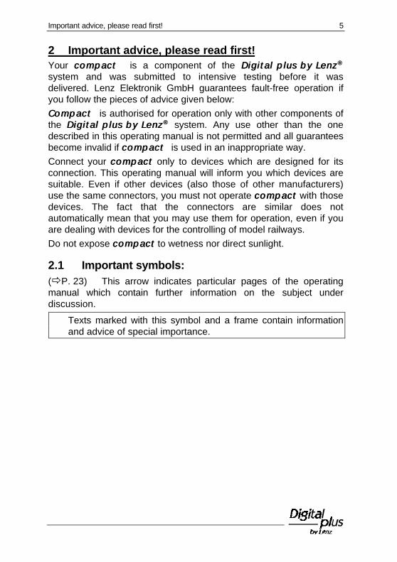
5.1.3 Switching on the device:Plug the mains-plug of the TR100 transformer into the mains socket.
On the compact compact display you will see:
Now your compactcompact is ready for work.
5.2 Controlling locomotivesPlace a locomotive that is equipped with a Dig i ta lD ig i ta l plus plus by by Lenz Lenz ®®
decoder on the tracks of your model railway layout (we assume herethat you use a locomotive with the address "3").
5.2.1 Selecting the locomotive address:The locomotive address is shown on the display. You can selectaddresses between 1 and 99.
You select the locomotive address by using the keys + and - (belowthe display):
You increase the number of the address by pressing the "+"key, and you decrease the number of the address by pressingthe "-" key. By keeping the respective key pressed, you canscroll up and down through the addresses.
5.2.2 Controlling the speed of the locomotive:You control the speed of the locomotive with the rotary control-knob.Turn it to the right to increase the speed, turn it to the left to decreasethe speed. The stop-limit to the left marks still-stand, the stop-limit tothe right marks maximum speed.
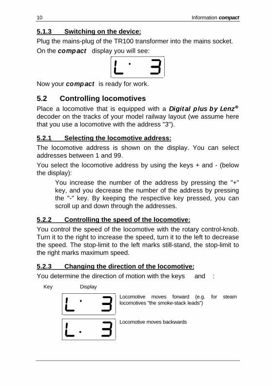
5.2.3 Changing the direction of the locomotive:You determine the direction of motion with the keys é and ê:
Key Display
é
Locomotive moves forward (e.g. for steamlocomotives "the smoke-stack leads")
ê
Locomotive moves backwards

First steps 11
The direction of motion will change only when you release pressureon the key. The display shows the chosen direction.If you change the direction while the locomotive is still in operation(rotary control-knob not at left-hand limit-stop), the locomotive willcome to a halt in accordance with the amount of delay-in-brakingwhich is set in the locomotive decoder. Afterwards it will speed upagain, also in accordance with the amount of delay-in-starting set inthe locomotive decoder, and move in the opposite direction.
5.2.4 Switching functions:To switch between the functions of your digital locomotives use thekeys F0, F1, and F2. The display informs you whether a function isswitched on or not:
F0F0
F0 switches the direction-dependentlighting in most digital locomotives on oroff. If this function is activated, the dotat the bottom left of the display willshine.
If function F1 is activated, the dot rightof centre at the bottom of the display willshine.
F2F2If function F2 is activated, the dot on thefar right-hand side at the bottom of thedisplay will shine.
To activate the function press the relevant key once, and todeactivate it press it again. All functions can be switched on and offindependently from one another.
That was a quick introduction to how to control locomotives and how toswitch functions on and off using your compact.

12 Information compact
6 Nothalt (Emergency stop)To trigger an emergency stop you press the S key. The voltage on thetrack is switched off and all locomotives stop immediately. Thefollowing message flashes on the display:
SS"OFF" flashes on the display. Thevoltage on the track is now switched off.
SS
By pressing the S key again, the voltageis reactivated. The locomotives calledupon last will speed up again with thespeed that was set before.
If you are within a menu when you press the key, the menu will beterminated.
7 Further functions of compact: the menusIn addition to controlling locomotives the compactcompact device enablesyou to use further functions:
• Switching points and signals• Setting the allocation of running-notches• Reading out and programming the locomotive address and other
features• Executing system settings
These additional functions are available via the compact compact menu.
7.1 Reaching the menu:Press the keys é and ê simultaneously. The display changes overto the menu. The menu displayed is always the one which waschosen last. When you switch on for the first time, the first menudisplayed is for the setting of the running-notches.
You can scroll up and down the menu with the +/- keys, to enter thedisplayed menu use the ü key (F0) (one level deeper), and with the ûkey (F2) you can go one level up.

Switching points and signals 13
8 Switching points and signalsPress the keys é and ê simultaneously. The display changes overto the menu. The menu displayed is always the one which waschosen last. If it is not the desired menu, scroll up and down with thekeys "+" and "-".
+ / -+ / -Menu, Switching points.
üü(F0)(F0)
Scroll up and down until the desiredaddress is displayed.
The possible range is 0 to 99. Set thedesired address and confirm with üü(F0)(F0) . Afterwards you can immediatelyswitch the point:
F0F0 Switches a point to one direction
F1F1 Switches the point to the oppositedirection
ûû(F2)(F2)
To leave the menu when you arefinished use the û key (F2).
While you are in the menu "Switching points", you can use the rotarycontrol-knob to control the locomotive whose number (address) wasshown in the display immediately beforehand.
For digital control of points, switch decoders are used
In the Dig i ta lD ig i ta l plus plus by by Lenz Lenz ®® programme, the switch decoderLS110, for example, is suitable for use with compactcompact . It is possibleto connect 4 points (signals, decouplers) to each of these switchdecoders. The switch decoder receives its information from theterminals J and K of compactcompact . For detailed information on theconnection of switch decoders please refer to the operatinginstructions for the switch decoder.
14 Information compact
9 Allocation of running-notchesThe range between standstill and the maximum speed of a locomotiveis divided into running-notches. The more precise this division themore notches exist. We call this division "Running-notch mode".Compact Compact supports 3 different running-notch modes: 14, 28 and 128running-notches.
When you switch on for the first time, the 28 running-notch mode isset for all addresses in compactcompact . The setting of the running-notchesis related to the locomotive address and stored for as long ascompactcompact is in operation.
FF You must ensure that the running notch mode setting of thecompactcompact . corresponds to the locomotive decoder setting. Thefollowing correlation is valid for Digital plus decoders:
Type of Digital pluslocomotive decoder
Supportedrunning-notch mode
NMRA compatible decoder XFseries
14/27, 28, 128
NMRA compatible decoders 14/27, 28
All others 14/27
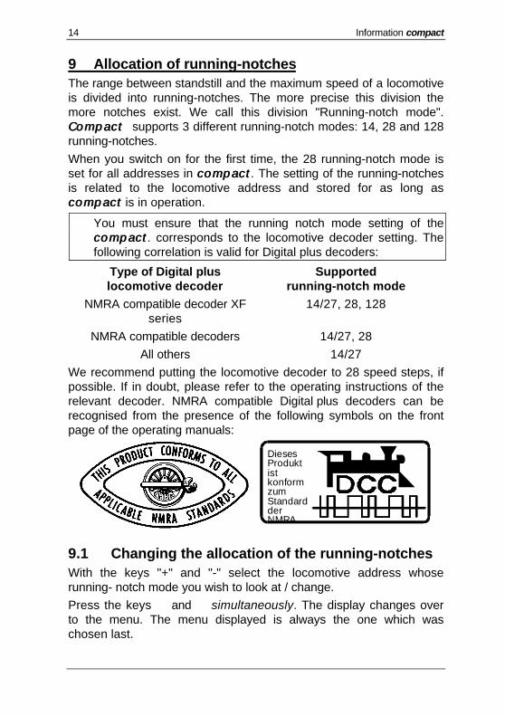
We recommend putting the locomotive decoder to 28 speed steps, ifpossible. If in doubt, please refer to the operating instructions of therelevant decoder. NMRA compatible Digital plus decoders can berecognised from the presence of the following symbols on the frontpage of the operating manuals:
DiesesProduktistkonformzumStandardderNMRA
9.1 Changing the allocation of the running-notchesWith the keys "+" and "-" select the locomotive address whoserunning- notch mode you wish to look at / change.
Press the keys é and ê simultaneously. The display changes overto the menu. The menu displayed is always the one which waschosen last.
Allocation of running-notches 15
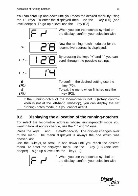
You can scroll up and down until you reach the desired menu by usingthe +/- keys. To enter the displayed menu use the ü key (F0) (onelevel deeper). To go up a level use the û key (F2)
When you see the notches-symbol onthe display, confirm your selection withü.
F0F0Now the running-notch mode set for thelocomotive address is displayed.
+ / -+ / -By pressing the keys "+" and "-" you canscroll through the possible settings.
+ / -+ / -
üü(F0)(F0)
To confirm the desired setting use theü key (F0).
ûû(F2)(F2)
To exit the menu when finished use theû key (F2).
FF If the running-notch of the locomotive is not 0 (rotary control-knob is not at the left-hand limit-stop), you can display the setrunning- notch mode, but you cannot alter it.
9.2 Displaying the allocation of the running-notchesTo select the locomotive address whose running-notch mode youwant to look at and/or change, use the "+" and "-" keys.
Press the keys é and ê simultaneously. The display changes overto the menu. The menu displayed is always the one which waschosen last.Use the +/-keys, to scroll up and down until you reach the desiredmenu. To enter the displayed menu use the ü key (F0) (one leveldeeper). To go up a level use the û key (F2).
When you see the notches-symbol onthe display, confirm your selection withü.

16 Information compact
F0F0Now the running-notch mode set for thelocomotive address is displayed.
+ / -+ / -By pressing the keys "+" and "-" you canScroll through the possible settings.
+ / -+ / -
ûû(F2)(F2)
To exit the menu without changing the running-notch mode,use the û key (F2)
10 Changing the locomotive address and otherdecoder features
10.1 General information on programmingEach locomotive with a digital decoder is addressed with its ownindividual number, the address. This address can be changed. We callthis procedure programming.In addition to the feature "address", you can also, among others, alterthe following other characteristics:
• Starting voltage• Starting delay• Braking delay• General settings
These features can be read out of the decoder and can be changed.The following features cannot be changed and can only be read out:
• Version number• Manufacturer's identification
For detailed information please refer to the operating instructions forthe decoders or the "Information on Digital plus locomotive decoders".Each feature has its own storage location inside the decoder, a so-called "register", in which a figure is stored. The content is keptunchanged until the next alteration takes place. Each register has itsown individual number.Register Description corresponding CVR 1 Address CV 1R 2 Starting voltage CV 2R 3 Starting delay CV 3
Changing the locomotive address and other decoder features 17
R 4 Braking delay CV 4R 5 General settings CV 29R 6 Not occupiedR 7 Version number CV 7R 8 Manufacturer's identification CV 8
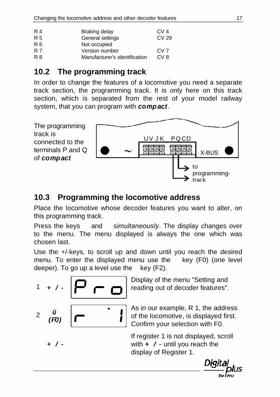
10.2 The programming trackIn order to change the features of a locomotive you need a separatetrack section, the programming track. It is only here on this tracksection, which is separated from the rest of your model railwaysystem, that you can program with compactcompact .
The programmingtrack isconnected to theterminals P and Qof compactcompact
U K CD
X-BUS
V PQJ
toprogramming-track
10.3 Programming the locomotive addressPlace the locomotive whose decoder features you want to alter, onthis programming track.
Press the keys é and ê simultaneously. The display changes overto the menu. The menu displayed is always the one which waschosen last.
Use the +/-keys, to scroll up and down until you reach the desiredmenu. To enter the displayed menu use the ü key (F0) (one leveldeeper). To go up a level use the û key (F2).
1 + / -+ / -Display of the menu "Setting andreading out of decoder features".
2 üü(F0)(F0)
As in our example, R 1, the addressof the locomotive, is displayed first.Confirm your selection with F0.
+ / -+ / -If register 1 is not displayed, scrollwith + / -+ / - until you reach thedisplay of Register 1.

18 Information compact
3 üü(F0)(F0)
If you want to read out the registernow, continue with step 4. If youwish to alter the register (write),proceed to Step 5.
4 üü(F0)(F0)
F0 starts the reading of the registerwhich was previously displayed. Ifthe reading procedure is completedsuccessfully, the value which hasbeen read out is displayed. If anerror occurs during the readingprocedure, you will receive an errormessage (see below).
5 + / -+ / -
If you wish to write a certain valueinto the register which waspreviously displayed, use + / - + / - tochoose the value which you wish toenter. Bear in mind the permittedrange of values (For more detailedinformation please refer to theoperating manual of the locomotivedecoder).
6 üü(F0)(F0)
To enter the value (programming)use the üü key (F0 (F0 )) . If theprogramming procedure iscompleted successfully, the enteredvalue will be displayed at the end ofthe procedure. If an error occursduring the programming procedure,you will receive an error message(see below).
7 ûû(F2)(F2)
To get back again to the display ofthe register, use the û key (F2).Now you can select a differentregister (using + / -+ / - ) or you canreturn to the menu selection bypressing the û key (F2) again.
The following error messages are displayed if an error occurs duringthe programming or reading out of a feature:

Changing the locomotive address and other decoder features 19
A short-circuit on the programming track hasoccurred and has been detected by the device.Check the track connection and the installationof the locomotive decoder.Do not attempt to use the locomotive on therunning track until you clear the short circuit
No value was found during the reading out of theregister or no feedback took place during thewriting. Check whether the locomotive is placedproperly on the programming track and/orwhether the decoder has been installedcorrectly in the locomotive.
10.4 Programming of other registersPlace the locomotive whose decoder features you want to alter onthe programming track.
Press the keys é and ê simultaneously. The display changes overto the menu. The menu displayed is always the one which waschosen last.
Use the +/-keys to scroll up and down until you reach the desiredmenu. To enter the displayed menu use the ü key (F0) (one leveldeeper). To go up a level use the û key (F2).
1 + / -+ / -Display of the menu "Setting andreading out of decoder features".
2 üü(F0)(F0)
As in our example, register 1(address of locomotive) is displayedfirst. Confirm your selection with F0.
+ / -+ / -Use + / -+ / - to scroll up or down untilyou reach the display of the registerwhich you wish to look at or alter.
Proceed as described under Step 3"Programming the locomotiveaddress".

20 Information compact
ûû(F2)(F2)
To get back again to the display of the register, use theû key (F2). Now you can select a different register (using+ / -+ / - ) or you can return to the menu selection bypressing the û key (F2) again.

System settings 21
11 System settingsHere you can
• read out the version number and the service number of thedevice. You need this number in case you have problems with thedevice and you wish to contact Lenz Elektronik
• set whether your compact is to work as an independent digitalsystem (command station) or as an additional input device(XpressNet input device).
The following system settings exist:
11Display / change XpressNet address(appears only with "Operation asXpressNet (XBUS) input device").
22Display version number.
33Display service number.
44Setting "Operation as independentdigital system" or "Operation asXpressNet (XBUS) input device".
The following sections will inform you how the individual systemsettings are displayed or altered.
11.1 Displaying the version numberPress the keys é and ê simultaneously. The display changes overto the menu. The menu displayed is always the one which waschosen last.
Use the +/-keys to scroll up and down until you reach the desiredmenu. To enter the displayed menu use the ü key (F0) (one leveldeeper). To go up a level use the û key (F2).
+ / -+ / -

22 Information compact
üü (F0)(F0)The first system-setting is offered. Use the +/-keys to scroll up and down until you reach thedesired system-setting "y11: version number".Confirm your selection with ü(F0).
üü (F0)(F0)The version number of the device isdisplayed (here version 3.0). To exitthe display use the ûkey (F2).
11.2 Displaying the service numberPress the keys é and ê simultaneously. The display changes overto the menu. The menu displayed is always the one which waschosen last.
Use the +/-keys to scroll up and down until you reach the desiredmenu. To enter the displayed menu use the ü key (F0) (one leveldeeper). To go up a level use the û key (F2).
+ / -+ / -
+ / -+ / -
Scroll with + / - until the desiredsystem setting "y12: service number"is displayed and confirm yourselection with ü(F0).
üü (F0)(F0) The service number of the device is displayed. To exit thedisplay use the û key (F2).
11.3 Setting compact on " Operation as XpressNet(XBUS) input device"
Connect your compact compact to the power supply (transformer) and plugthe connector into the socket.
Press the keys é and ê simultaneously. The display changes overto the menu. The menu displayed is always the one which waschosen last. Scroll with the keys +/- until you reach the menu SYS
+ / -+ / -

System settings 23
üü (F0)(F0)The system setting which was chosenlast is offered.
+ / -+ / -Scroll with + / - until the systemsetting 90 is displayed.
üü (F0)(F0)
On delivery, the setting " Operationas independent digital system" isdisplayed.
--Use + / - to alter the setting to"Operation as XpressNet (XBUS)input device".
üü (F0)(F0)Confirm your setting with üü (F0)(F0) .
Switch the power supply of compact compact off again. Now, your compactcompactis set to operation as an XpressNet (XBUS) input device.
11.4 Setting compact to "Operation as independentdigital system"
If you wish to alter the setting of your compact compact from operation asan XpressNet device back to operation as an independent digitalsystem, then proceed as follows:
Connect your compact compact to the power supply (transformer) and plugthe connector into the socket.
Press the keys é and ê simultaneously. The display changes overto the menu. The menu displayed is always the one which waschosen last.
Scroll with the keys +/- until you reach the menu SYS
+ / -+ / -
üü (F0)(F0)The system setting which was chosenlast is offered.

24 Information compact
+ / -+ / -Scroll with + / - until the systemsetting 90 is displayed.
üü (F0)(F0)The last setting "Operation asXpressNet (XBUS) input device" isdisplayed.
--Use + / - to alter the setting to"Operation as independent digitalsystem".
üü (F0)(F0)Confirm your setting with üü (F0)(F0) .
Switch the power supply of compact compact off again. Now, your compactcompactis set to operation as an independent digital system.
11.5 Setting the XpressNet addressFF While setting the XpressNet address, please bear in mind to
which device you wish to connect your compactcompact . The followingaddresses / ranges of addresses can be set:Connection to command station LZ100: 1 - 31Connection SET02, SET03 and compactcompact : 1, 2, 3, 29 and 31.You must not on any account use an address to which adifferent device has already been set!
FF You can alter the XpressNet (XBUS) address only if yourcompact compact is set to "Operation as XpressNet input device".
On delivery, compact compact is set to the XpressNet address "3". If adifferent Digital plus device is already set to this address, you willhave to alter the address of compact compact to a different, free address.
In order to set the XpressNet address proceed as follows:
Press the keys é and ê simultaneously. The display changes overto the menu. The menu displayed is always the one which waschosen last.
Scroll with the keys +/- until you reach the menu SYS
+ / -+ / -
Combined operation with a second compact 25
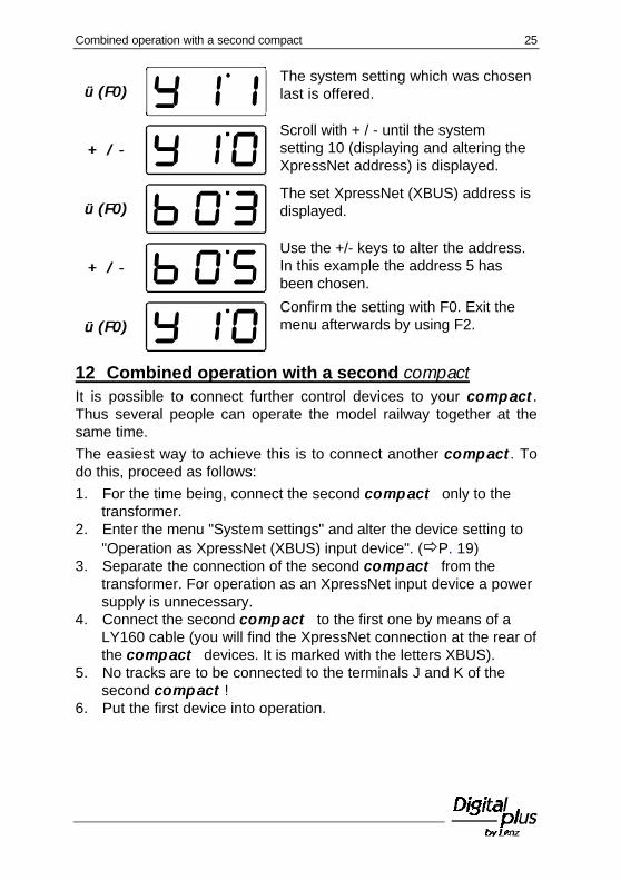
üü (F0)(F0)The system setting which was chosenlast is offered.
+ / -+ / -Scroll with + / - until the systemsetting 10 (displaying and altering theXpressNet address) is displayed.
üü (F0)(F0)The set XpressNet (XBUS) address isdisplayed.
+ / -+ / -Use the +/- keys to alter the address.In this example the address 5 hasbeen chosen.
üü (F0)(F0)Confirm the setting with F0. Exit themenu afterwards by using F2.
12 Combined operation with a second compactIt is possible to connect further control devices to your compactcompact .Thus several people can operate the model railway together at thesame time.
The easiest way to achieve this is to connect another compactcompact . Todo this, proceed as follows:
1. For the time being, connect the second compact compact only to thetransformer.
2. Enter the menu "System settings" and alter the device setting to"Operation as XpressNet (XBUS) input device". (ðP. 19)
3. Separate the connection of the second compact compact from thetransformer. For operation as an XpressNet input device a powersupply is unnecessary.
4. Connect the second compact compact to the first one by means of aLY160 cable (you will find the XpressNet connection at the rear ofthe compact compact devices. It is marked with the letters XBUS).
5. No tracks are to be connected to the terminals J and K of thesecond compactcompact !
6. Put the first device into operation.
26 Information compact
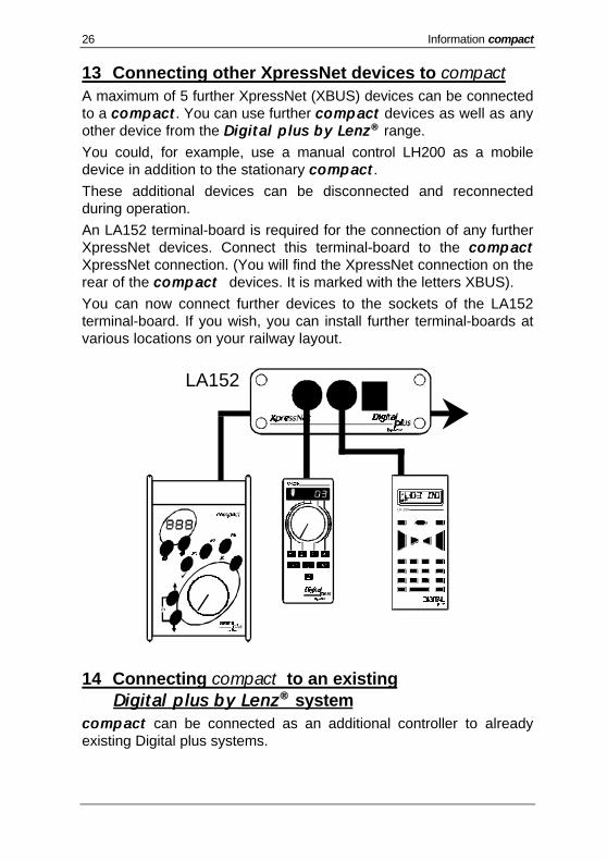
13 Connecting other XpressNet devices to compactA maximum of 5 further XpressNet (XBUS) devices can be connectedto a compactcompact . You can use further compactcompact devices as well as anyother device from the Dig i ta lD ig i ta l plus plus by by Lenz Lenz ®® range.
You could, for example, use a manual control LH200 as a mobiledevice in addition to the stationary compactcompact .
These additional devices can be disconnected and reconnectedduring operation.
An LA152 terminal-board is required for the connection of any furtherXpressNet devices. Connect this terminal-board to the compactcompactXpressNet connection. (You will find the XpressNet connection on therear of the compact compact devices. It is marked with the letters XBUS).
You can now connect further devices to the sockets of the LA152terminal-board. If you wish, you can install further terminal-boards atvarious locations on your railway layout.
LH 100
LA152
14 Connecting compact to an existingDigitalDigital plus plus by by Lenz Lenz ®® system
compactcompact can be connected as an additional controller to alreadyexisting Digital plus systems.

More power for your model railway 27
On delivery, compactcompact is set to operation as an independent digitalsystem. Before you connect it to a Digital plus system as anadditional controller, you must alter the system settings to thisoperating mode.
To do this, proceed as follows:
1. For the time being, connect the second compact compact only to thetransformer.
2. Enter the menu "System settings" and alter the device setting to"Operation as XpressNet (XBUS) input device". (ðP. 19)
3. Separate the connection of the second compact compact from thetransformer. For the operation as an XpressNet input device, apower supply is unnecessary.
4. By means of a no. 80006 cable, connect the compact compact to theLA150 or LA152 terminal-board of your Dig i ta lD ig i ta l plus plus by by Lenz Lenz ®®
system.
5. If necessary, alter the default XpressNet address.
FF No tracks are connected to the terminals J and K if compact compact isconnected as an XpressNet device!
14.1 Using compact as separate programming deviceIf you operate your compactcompact as an XpressNet device with aDig i ta lD ig i ta l plus plus by by Lenz Lenz ®® system, you can still use the connection forthe programming track. In this case, however, compactcompact has to besupplied by its own individual transformer.
1. Prepare your compact compact for the operation as an XpressNet(XBUS) input device (ðP. 23).
2. Connect a programming track to the terminals P and Q ofcompactcompact .
3. Put compact compact into operation in a Dig i ta lD ig i ta l plus plus by by LenzLenz ®®
system.
4. Connect compactcompact with the terminals U and V to a separatetransformer.
You can now use the connected programming track. The operation isthe same as in the section "Changing the locomotive address andother decoder features" (ðP. 14).
15 More power for your model railway
28 Information compact
Railways running on the system consume power, as do illuminatedcoaches.
Your compact compact is able to supply a maximum of 2.5 A to the modelrailway. If the trains and illuminated coaches which you have inoperation consume more than 2.5 A, you will have to divide yoursystem among various power circuits and supply each circuit with anLV101 amplifier.
Each amplifier requires its own separate transformer. We recommendthe use of a TR100.
15.1 Connecting the LV101 to compactDivide your model railway between two power circuits. You need aLV101 and a TR100v transformer for the second power circuit.
1. Connect the terminals C and D of compact compact to the terminals Cand D of the amplifier LV101.
2. Connect the tracks of the first power circuit to the terminals J andK of compactcompact .
3. Connect the tracks of the second power circuit to the terminals Jand K of the LV101.
4. Connect compact compact and the LV101 to a TR100 transformer each.

More power for your model railway 29
Power circuit 1 Power circuit 2
J K J K
LV101
C C U VD DU V
toTR100
toTR100

30 Information compact
16 Technical appendix
16.1 Messages on the display
compact compact always shows a message if you have done somethingwhich is not permissible at the time or if a certain function cannot beexecuted.
The following is a list of possible messages:
Er 1 An overload (short-circuit) was detected during theprogramming or reading out procedure of a decoder. It ispossible that the decoder is not properly connected orthat it is defective.
Er 2 No information was found during the programming orreading out of a decoder. This means that it is possiblethat the decoder was not connected correctly to theprogramming output of the command station LZ100 (e.g.the digital locomotive is not placed properly on theprogramming track).
Er 8 The command sent from compact compact to the commandstation is not part of the station's range of commands.Normally this happens if the software version of thecommand station does not support this command. Pleaseread out the software version of your command stationand contact your specialist dealer or Lenz GmbH.
Er 9 No communication with the command station via theXpressNet exists. The F0 key will lead you directly to thesystem setting.1. Check whether compact compact is configured for the
operation as an XpressNet input device (ðP. 19).
2. Check whether the set XpressNet address is freeand/or whether it is really supported by the commandstation (ðP. 23)

Technical appendix 31
16.2 GlossaryThe most important terms in the Digital plus by Lenz® system:
Address Number of a locomotive, comparable to a telephone number
Starting - andbraking-delay
Features of a locomotive decoder. The starting-delay determineshow long it takes a locomotive to reach its allocated higher speedsetting. The braking-delay determines how long it takes alocomotive to reach its allocated lower speed setting.
DCC Abbreviation for "Digital Command Control". This term hasmeanwhile become the name of the digital command control thatwas developed by Lenz in keeping with NMRA standards.
Features of thelocomotivedecoders
Address, starting- and braking-delay , for example, are featureswhich can be altered in the locomotive decoder. You will finddetailed information on the features of Digital plus locomotivedecoders in "Information on Digital plus Locomotive decoders",available from your specialist dealer or direct from Lenz ElektronikGmbH ( send a stamped addressed C5 envelope).
Running-notch The range between the minimum and maximum speed is divided intoindividual sections. These sections are called running-notches.
Running-notchmode
Determines whether a locomotive is controlled with 14, 28 or 128running-notches.
Track format The way in which the information is stored in the voltage for thetracks.
Locomotiveaddress
See Address
NMRA North American Railroad Association, (American model railwayorganisation)
NMRAnormalisation,standardisation
A standard developed by the NMRA on the basis of the Digital pluscontrol, which determines the transfer of information to locomotivedecoders and points decoders. This standard defines thepreconditions which ensure the inter-changeability of decodercomponents produced by different producers in accordance withthe standard.
XpressNet Fast network via which the devices of the Dig i ta lD ig i ta l p lus p lus by by Lenz Lenz ®®
system exchange data.
XBUS-inputdevices
Devices by which the Digital plus model railway is controlled:manual controls, signal boxes, interface etc.

32 Information compact
17 Help in cases of malfunctionMalfunction Possible cause Correction
Locomotive does notwork.
Wrong locomotive address ondisplay.
Scroll through the deck untilyou find the correct addressor enter the correct addressinto the deck.
Running-notch modecannot be altered.
Speed of the locomotive is not0.
Before setting the running-notch mode turn the rotarycontrol-knob as far to theleft as possible.
Locomotive does notreact when running-notch mode 128 hasbeen selected.
Locomotive decoder can notmaster this mode.
Set compact to running-notch mode 14 or 28depending on locomotivedecoder notch setting
Locomotive lighting (F0)switches on and off whenthe rotary control-knob isturned.
Locomotive decoder is set atrunning-notch mode 14. Therelevant address is set in thecompact compact to running-notchmode 28.
Alter the running-notchmode of the compact compact to14 notches for relevantaddress
Locomotive lighting (F0)cannot be switched.
Locomotive decoder is set atrunning-notch mode 28. Therelevant address is set in thecompact compact to running-notchmode 14.
Alter the running-notchmode of the compact compact to28 notches for relevantaddress
Locomotive decoder is set atrunning-notch mode 14. Therelevant address is set in thecompact compact to running-notchmode 128.
Alter the running-notchmode of the compact compact to14 notches for relevantaddress
Locomotive address onthe display flashes.
Selected address is alreadybeing used on a differentmanual control.
Select a different locomotiveor take over the locomotiveby turning the rotary knob.
"OFF" flashes on thedisplay.
The Stop-key has beenpressed.
Terminate the NOTHALT bypressing the Stop-keyagain.
Compact has triggered theNOTAUS (Emergency stop)due to a short-circuit oroverload.
Deal with the short circuit. Ifthere is overloading, dividethe layout into severalcoverage areas. Pleaserefer to the section "Morepower for your modelrailway" for more detailedinformation.

Help in cases of malfunction 33
This page has been intentionally left blank.
34 Information compact
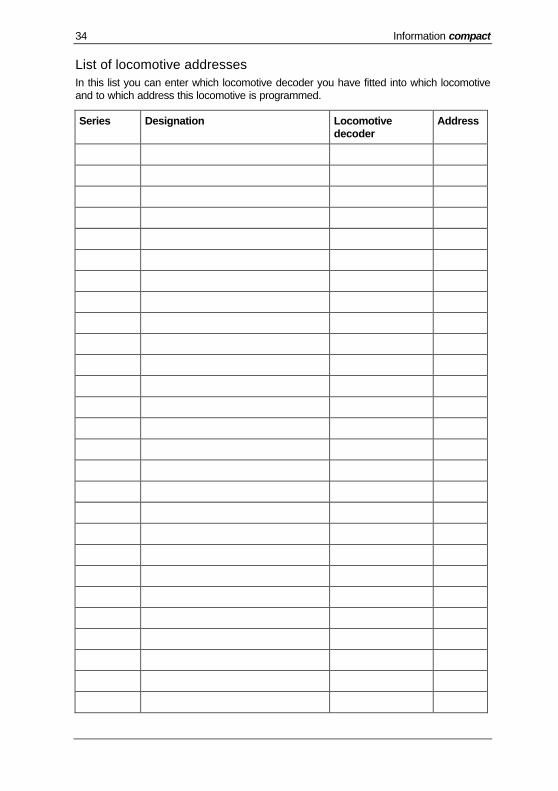
List of locomotive addressesIn this list you can enter which locomotive decoder you have fitted into which locomotiveand to which address this locomotive is programmed.
Series Designation Locomotivedecoder
Address

Help in cases of malfunction 35
Series Designation Locomotivedecoder
Address
36 Information compact
Not suitable for children under three because of the danger of their swallowing the smallconstituent pieces. Improper use can result in injury by functionally necessary sharpprotuberances and edges. For use only in dry areas. We reserve the right to makechanges in line with technical progress, product maintenance or changes in productionmethods. We accept no responsibility for errors which may occur for similar reasons.We accept no responsibility for direct or indirect damage resulting from improper use,non- observance of instructions, use of transformers or other electrical equipment whichis not authorised for use with model railways, or use of transformers or other electricalequipment which has been altered or adapted or which is faulty. Nor can we acceptresponsibility when damage results from unsupervised adjustments to equipment or fromacts of violence or from overheating or from the effects of moisture etc.. Furthermore, inall such cases guarantees become invalid.
Hüttenbergstrasse 2935398 Giessen
Hotline: 06403 900 133Fax: 06403 900 155www.digital-plus.de
www.lenz.come-mail: [email protected]
Keep this operation manual for future reference!