informacion tecnica del libro electric power distribution de t.a. short
TRANSCRIPT
TTECTRIC PO\,\TERDISTRIBUTION
HANDBOOK
T.A. SHORT
CRC PRESSBoca Raton London New York \(CIhington, D.C.
(C) 2004 by CRC Press LLC
N €uT¿a¿or¡ecTAD?F -t - rÉ¿f1A
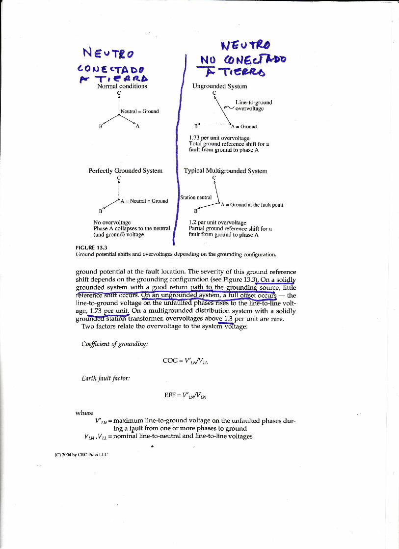
Normal conditions
Neutral = Ground
A=Neutral=Ground
No overvoltagePhase A collapses to the neutral(and ground) voltage
line-to-ground voltage on
Earth fault factor:
\I neutral \
f--- ^= Ground atthe faultpoint
FIGURE 13.3Ground potential shifts and overvoltages depending on the grormding configuraüon.
ground potential at the fault locaüon. The severity of this ground referenceshift depends on the grounding configuration (see Figuru 13.3}€Lggglidlygrounded system with a good retum path to the grounding soúrce, little
- thevolt-
age,1.-73 per unit, On a multigrounded distribuüon system with a solidlygrouRÉffittransrorrner, overvoitages above t.c per urur are rare.
Two factors relate the overvoltage to the system-!6ltige:
Coefficient of grounding:
COG = V'r*Nn
EFF = V'wNu,t
whereV'LN=maximum line-to-ground voltage on the unfaulted phases dur-
ing a fault from one or more phases to groundV¡¡¡ ,Vu= nominal line-to-neutral and line-to-line voltages
uÉotloNO
- FONé¿¡n/D"
TtÚ'?t?4,Ungrounded System
C
Line-to-groundt\-z overvoltage
1.73 per unit overvoltageTotal ground reference shift for afault from ground to phase A
Typical Multigrounded S ystemC
1.2 per unit overvoltagePartial ground reference shift for afault from ground to phase A
(C) 2004 by CRC Press LLC

A system is ,'effectrvely grounded" if the coefficient of grounding is less
than ór equal to 80% (the earth-fault factor is less than 138%) (ANSI/IEEE
c62.g2-]9bn This is met approximately with the following conditions:
'Xf lX: '<3
' Ro/X1 < 1
For a singie line-to-ground fault on phase A, the voltages on phases B and
C are
( z,-2" )-1/ - ln+ ' " l ¡ -
" - f - '
22,+zo+3R, )"
whereZ, = p osrlve-sequence imPedanceZ o = zeto-sequence impedancea = 71120"
Rr = fault resistanceE = line-to-neutral voltage magnitude prior to the fault
For a double line-to-ground fault, the voltage on the unfaulted
, r 3Zo+6R, rv = Zt+zlo +6Rr'
phase is"-/4
i;cóleft>o
ío-ground fault. For single line-to-groyndfaults, the voltage is always worse
wiin tne fault impedance Rr= 0. For double line-to-ground faults, it may not
always be worsé with Rp = 0' FigFre 13'4 shows overvoltage charts as a
funcáon of Xs/X1and Ro/&.This includes o1e_r'gltages due to *ngle tq1-
to-ground faults and for double line-to-ground faults (qssuming that RF: 0).
hr some cases, the d
gtórroá farilts are so much more common lve.oftel design for the single line-
tÉEU suggests the overvoltage multipter factors for different system:
shown in Table 13.1 (IEEE C6292.4.199I)'shift during |¡s-to-srourd farrtts at a voltare of 1057o-(so, the-
overvoltageof 1.35-for mulüerounded systems withThe higher ovGÑlJlagfiactor of 1.35 tor muttproundecl- sy
metal-oxiáe affesters wás idenüfied as a more con\rvative factor for four-
wire systems becauáe of the reduced saturation of n\wer transformers andwrre syrrc ' rD ucLq."r vr urv _
\ ^ l
\* T
(c,2oo*bvcRCPresslLC \ l .Bf ly>i
\ eJdif$¡ilfrásgf'