info ...more than 90 percent of open channel flows are measured by the use of flumes and weirs. ......
TRANSCRIPT

WWW.FLOWTECHPLASTICSLIMITED.CO.UKINFO@FLOWTECHPLASTICSLIMITED.CO.UK
TEL 01204 849898FAX 01204 819019
FLOWTECH PLASTICS LTDUNIT AWORDSWORTH TRADING ESTATEWORDSWORTH STREETBOLTON . BL1 3ND

Flowtech Plastics is committed to the highest standards in engineering manufacture and plastics engineering.Our previous success over the years is based upon our ability to pay careful attention to all customers needs, by providing high quality products with individual and professional service.
We will never sacrifice quality for cost, but rely on our extensive experience and design ability to provide you with the correct solution to your requirements. Our products are always of the highest quality and workmanship at a very competitive pricing structure.
Our overall company strategy is based upon customer care and not group sales. We are proud of our high quality products and aim to exceed expectations on quality and standards.
Our company is committed to continuous quality improvements on all our product range,service and staff operations.
As an additional service,we are also suppliers and fabricators of Plastic Fume Extraction Ductwork Systems, Fans, Fume scrubbers and Glass Fibre reinforcement and moulding facilities.
As a new addition to our range of products, we are now able to supply a standard sized GRP Kiosk for the housing and protection of instruments, control panels and other items of equipment.
If you are replacing existing facilities or creating a new one, please contact us to find out more about the flowtech range, or visit our website.
Paul BickerstaffeManaging Director
info@flowtechplasticslimited.co.ukwww.flowtechplasticslimited.co.uk
Tel 01204 849898Fax 01204 819019
2
YOUR PARTNER FOR SUCCESS

Flowtech Plastics LtdUnit AWordsworth Trading EstateWordsworth StreetBolton BL1 3ND01204 [email protected]
3
INDEX
FLUMES PAGE
DRAIN SEWER FLUMES 8DRAIN SEWER INSTALLATION 20FLUME INSTALLATION 19PALMER BOWLUS FLUMES 9PARSHALL FLUMES 10 RECTANGULAR FLUMES 7 TRAPEZOIDAL FLUMES 11U SHAPED FLUMES 7
WEIRS
CRUMP WEIR 12FLAT “V” WEIR 12V NOTCH WEIR PLATES 13WEIR PLATE WITH DRAIN DOWN 14WEIR TANKS 15WEIR TANK WITH V NOTCH 17WEIR PLATE INSTALLATION 21
OTHER PRODUCTS
BIOLOGICAL CONTAINMENT CABINET 25CABINETS/KIOSKS 22CABLE ACCESS POINT 27ENCLOSURES 22FROST PROTECTION 26PVC WALL BOARD 27SENSOR BRACKETS 16SPLITTER TANK 27STORAGE CONTAINER 27

Applications For use as primary gauging structures where open channel flow measurement and flow control are required. Typical locations include waste water treatment works and trade effluent Discharges Standard Compliance All flumes supplied are normally compliant with BS 3680, If, however, a client specifically requires a non-compliant design, this can also be supplied. Flume Types Both rectangular and round bottom flumes are available as complete one- piece structures. Rectangular flumes are also available as pairs of flume cheeks. Principal Features • Extremely rigid construction helps prevent distortion during installation • Strengthening ribs and flanges are standard for grouting into channel walls and floor, (Standard width of ribs and end flanges is 50 mm on both sides and bottom)
• The reinforcing ribs include grout holes to provide additional keying. Butterfly-ties or steel bars can be passed through the grout holes before installation. • The end flanges can be used to bolt on to upstream and down-stream preformed sections. Where we are supplying both flume and additional channel sections the end flanges are pre-drilled and • supplied with nuts, bolts and gaskets. • Very large flume liners can be supplied in flanged bolt-together sections. • All flume liners are braced across the top flanges to provide additional rigidity during transportation and installation. • The bottom flanges can be fitted with stainless steel angle brackets. This enables the flume liner to be bolted into position, within a “boxed-out” channel section, to prevent it from floating as the • concrete is poured around it
Options • Internal plywood shuttering. This is recommended to maintain the accuracy of internal dimensions during installation. • Preformed structures upstream and down stream of the flume. These can include: break-tanks. Approach channels, discharge sumps and side overflow weirs. • Plain or flanged spigots can be provided for connection to upstream and downstream pipe work. • Stilling chambers are available for applications where sensors, probes or sampling points are required outside of main approach channel. • Flumes are normally supplied with level inverts. Raised Inverts (flume humps) can be incorporated into any design
Robust rigid structures for ease of installation without distortion. Standard and non-standard designs available Full range of preformed approach channels and discharge sumps available
Open Channel Flume Liners
DA
TA
SH
EE
T
Flowtech Plastics LtdUnit AWordsworth Trading EstateWordsworth StreetBolton BL1 3ND01204 [email protected]
4

Often a new flow measurement system requires only the installation of a weir or flume into an existing channel at a location where the hydraulic conditions meet the requirements of the standard. Installations requiring a new channel are more costly. The design stage is crucial: paying attention to the details of the hydraulics of the channel can minimise the civil engineering costs of the system.
More than 90 percent of open channel flows are measured by the use of flumes and weirs. The reliability and simplicity of these ‘measuring structures’ account for this widespread use.
The advantages of weirs and flumes is that they can be inspected in the field and their accuracy determined at any time by reference to the published standards. This is not so with pipe flows and other open channel measurement techniques, where the user is dependant on original certification by the manufacturer.
Flowtech Plastics LtdUnit AWordsworth Trading EstateWordsworth StreetBolton BL1 3ND01204 [email protected]
5

All flumes manufactured by Flowtech Plastics Ltd are designed to comply with B.S
3680 part 4-C.Customers have a choice of flumes that are manufactured from either Plastic materials or stainless steel to suit site requirements.
Flow rates are more accurately achieved by having a smooth transition between the ap-
proach channel and the inlet of the flume, for this reason we recommend a section of
approach channel also manufactured from any of the above
materials.The approach channel can be supplied
already attached to the flume ,or for longer channels,supplied in sections for site
installation.
FLUMES and WEIRS Suitable for open channel flow measurements
FLUMES Rectangular Flumes: Throat width 100 mm. > 1000 mm Flow range 0-5 l/s to 0-2000 l/s. U-Shaped Flumes: As per Rectangular flumes. Trapezoidal Flumes: Flow range 0-50 l/s to 2000 l/s. Parshall Flumes: As per Standard designs. Drain Sewer Flumes: Temporary insert Flumes for sewers or industrial discharges.
WWW.FLOWTECHPLASTICSLIMITED.CO.UK 6

Please note: To comply with British Standard BS3680, the length of the approach channel to a rectangular or U-shaped flume must be at least five times the width of the water at maximum flow. However, if the effluent is approaching from a steep gradient, or other conditions result in hydraulic jump, then the approach channel should not be less than thirty times the maximum head (see BS3680 Part 4C,6.2.2.2 and 6.2.2.6) Flowtech Plastics Ltd design and manufacture alltypes of Flow controls including Rectangular,Round Bottom Flumes, Rectangular and "V" NotchWeirs,Tanks and Drain Sewer Flumes. Whereverapplicable designs comply with ISO or British Standards. A standard range of 6 rectangular flumes are available to meet many typical installations. Detailsand capacities are printed below. If the standard sizes do not meet your requirements, we will be pleased to design and manufacture a purposebuilt unit.Accurate flows are more easily achieved by having a smooth transition between the approach channel and the inlet of the flume. For this reason, we recommend a section of approach channel, this can be supplied already attached to the flume, or for longer channels, supplied in sections with gaskets and simply bolted together on site.
FLUMES: RECTANGULAR/U SHAPED
WWW.FLOWTECHPLASTICSLIMITED.CO.UK 7
STANDARD SIZE 1 2 3 4 5 6
Dimensions in mm Channel width 150 250 300 500 750 1000Throat width 100 150 180 300 450 600Wall Depth 250 300 350 500 650 900Overall Depth 300 350 400 550 700 950Throat Length 400 450 580 750 1140 1560Overall Length 616 882 1099 1614 2437 3289Overall width 250 350 400 600 850 1100Max Flow Rate L/S 15 30 50 120 350 750Upstream Max Head Flow 189 231 287 364 568 778
SIZE CHART
Flowtech Plastics LtdUnit AWordsworth Trading EstateWordsworth StreetBolton BL1 3ND01204 [email protected]

Designed originally to conduct surveys. These flumes are manufactured to be temporarily installed in manholes and provide a known head/discharge relationship. The flumes provide a simple method of assessing trade effluent discharges or can be installed as a permanent fixture for a fraction of the cost of an equivalent standing wave flume. A range of standard sizes are available printed below or individual flumes can be custom designed to fit into an existing manhole
In order to measure flows, the ultrasonic
sensor (or other) should be located upstream of
the flume and the dimensions keyed in as
per a rectangular flume, ensuring that
zero depth corresponds to the hump height. The flumes are particularly
suited for use with crude sewage where they perform without
ragging up.
DRAIN SEWER FLUMES
WWW.FLOWTECHPLASTICSLIMITED.CO.UK
standard sizes (mm) 1 2 3
Flow rate/sec 4 12 25
Gradient 1:100 1:100 1:100
Drain diameter W 150 230 300
Throat width b 90 125 180
Overall Length L 350 535 720
Height H 115 185 250
8

Palmer Bowlus FlumesLow Flow Flumes
WWW.FLOWTECHPLASTICSLIMITED.CO.UK
Palmer Bowlus Flumes:The Palmer Bowlus metering flume has been widely used since 1937 for meas-uring water and wastewater in open channels or pipelines that are not under pressure.Some of its most important char-acteristics include measurement accuracy, low head loss, minimum flow restriction and ease of installation in pipelines
AccuracyThe accuracy of the Palmer Bowlus flumes is comparable to that of Parshall or other types of Venturi flumes. Experiments indicate that within the normal range of flows (from under 10% to 90% of flume capacity),measurement accuracy is usually within +/- 3% of flow rate
The Palmer Bowlus is normally installed in a “U” shaped channelfed by a pipeline such as storm drains and sewers. This convenient flume requires little redesign or special modification of circular conduits for installation.
9

The Parshall flume is a specially shaped structure, which can be installed in a channel to measure the water flow rate. This type of flume was developed and cali-brated in the 1920’s by Ralph Parshall at Colorado State University and, although they are difficult devices to set and build, they are frequently used in industrial and municipal sewers, sewage treatment plants, irrigation canals and certain natural channels, mainly in the U.S.A. and Mainland Europe. The principal advantages of the parshall flume are it’s capabilities for self-cleaning (particularly when compared with sharp edged weirs). Its relatively low head loss and its ability to function over a wide operating range, whilst requiring only a single head measurement.
PARSHALL FLUME
WWW.FLOWTECHPLASTICSLIMITED.CO.UK 10

TRAPEZOIDAL FLUMES
Trapezoidal flumes, originally developed to measure flows in Irrigation channels, are well suited for low flow applications in conduits and manholes. For storm water or agricultural applications, the Trapezoidal flume is superior to the Parshall flume for several reasons, The shape of the trapezoidal flume conforms to the normal shape of culverts and ditches reducing installation costs. Also, the straight through design allows for the passage of large amounts of trash and reduces the problem of silting.
Trapezoidal flumes can be supplied to cope with a wide variation of flow conditions. The optimum design will depend on the range of flow to be measured and the characteristics of the stream or channel in which it is to be installed. Flumes supplied for use within the U.K. are normally required to comply with BS3680. Although non compliant designs are available. Trapezoidal flumes have a “V” shaped throat providing the ability to measure low flows accurately whilst avoiding the inherent problems associated with “V” notch weirs. They have a flow range of 0 to 2000 litres per second. The construction of the flume is PVC backed with GRP to provide strength and rigidity which helps prevent distortion during installation. They can also be supplied in flanged bolt-together sections.
As supplied to Critical Flow Systems Ltd
WWW.FLOWTECHPLASTICSLIMITED.CO.UK 11

Flat-V Weir: A long-base weir with a triangular longitudinal profile. The height of the triangle increases linearly from the middle of the channel to the abutment of the weir.
The Weir is manufactured from grey rigid 9mm PVC sheet. All joints are fully welded.
Long-base weir with a triangular or other shape of longitudinal profile and a transverse symmetrical V-shaped crest having small side-slopes
Flat V weir - 2.75m wide; constructed in 1974 to supersede the original broad-crested weir operated by Stevenage Development Corporation - flow records prior to 1974 are sporadic and of poor quality. The Flat V weir remains modular up to 4.1 cumecs; higher floods uncorrected. Gw abstractions (net export) and the release of water from flood storage lagoons can influence the flashy flow regime.
crump weirs & flat ‘v’ weirs
WWW.FLOWTECHPLASTICSLIMITED.CO.UK
FLAT ‘V’ WEIR
Flowtech plastics Limited are able to design & supply a range of Crump and Flat ‘v’ Weirs,commonly used for measuring streams and rivers, or where there is a large flow rate span. These Weirs are designed to comply with the British Standard BS3680 Part 4B/4G
CRUMP WEIR
12

Flowtech Plastics will design and supply any size V Notch or rectangular weir plate to suit your requirements. They can be supplied either as a flat plate for mounting on an existing tank or chamber, or supplied as part of a weir tank .All weirs are designed to comply with the British standard BS3680 part 4A
Crump (Triangular profile) Weirs Flat-V (V-Crump) Weirs Flowtech Plastics can also design and supply a range of Crump and Flat-V weirs, commonly used for measuring streams and Rivers, or where there is a large flow rate span. These weirs are designed to comply with the British standard, BS3680 part 4B/4G
WWW.FLOWTECHPLASTICSLIMITED.CO.UK
V Notch Weirs and Rectangular Weirs
13

V Notch Weirs and Rectangular Weirs Flowtech Plastics will design and supply any size V Notch or rectangular weir plate to suit your requirements. They can be supplied either as a flat plate for mounting on an existing tank or chamber, or supplied as part of a weir tank complete with flow baffles and sensor mounting bracket. The weir tanks are of robust construction and have an inward facing top flange for extra rigidity, and require only a level concrete plinth when Installing. In our tanks, all weir plates are bolted into place, so that as your company grows, if the flow discharge increases, the weir plate can be removed and replaced with a more appropriate size. All weirs are designed to comply with the British standard BS3680 part 4A.
WEIRS Thin plate: Rectangular: Suppressed, partially developed and fully developed Weir width: 300 mm. > 3000 mm. Flow range 0-5000 l/s. V Notches: Standard sizes - 90 degrees, Half 90 and Quarter 90. Flow range 0-100 l/s, 0-20 l/s. Broad Crested Weirs: Manufactured to customer requirements as per BS3680.
DRAIN DOWN VALVE As an optional extra facility, a water tight drain-down valve assembly can be attached to a weir plate to allow drain down of the chamber for cleaning purposes. The handle being complete with a lockable devise to prevent use by unauthorised personnel. The use of these units being subject to approval of the end user.
WEIR PLATE with drain-down facility
WWW.FLOWTECHPLASTICSLIMITED.CO.UK 14
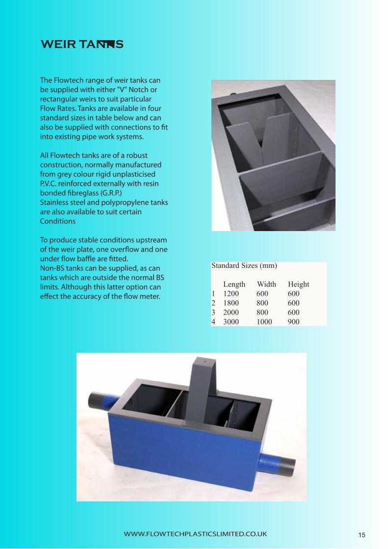
The Flowtech range of weir tanks can be supplied with either "V" Notch or rectangular weirs to suit particular Flow Rates. Tanks are available in four standard sizes in table below and can also be supplied with connections to fit into existing pipe work systems. All Flowtech tanks are of a robust construction, normally manufactured from grey colour rigid unplasticised P.V.C. reinforced externally with resin bonded fibreglass (G.R.P.) Stainless steel and polypropylene tanks are also available to suit certain Conditions To produce stable conditions upstream of the weir plate, one overflow and one under flow baffle are fitted. Non-BS tanks can be supplied, as can tanks which are outside the normal BS limits. Although this latter option can effect the accuracy of the flow meter.
WEIR TANKS
WWW.FLOWTECHPLASTICSLIMITED.CO.UK
Standard Sizes (mm)
Length Width Height1 1200 600 6002 1800 800 6003 2000 800 6004 3000 1000 900
15
SENSOR BRACKET
WWW.FLOWTECHPLASTICSLIMITED.CO.UK
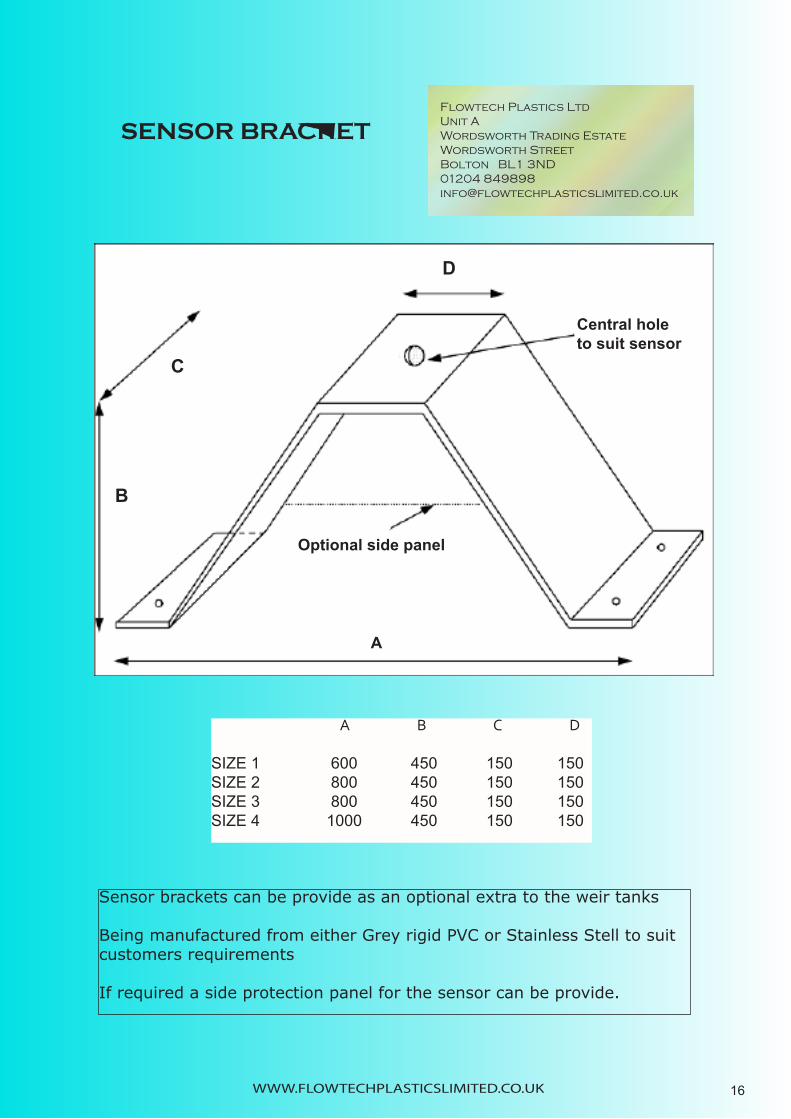
Sensor brackets can be provide as an optional extra to the weir tanks
Being manufactured from either Grey rigid PVC or Stainless Stell to suitcustomers requirements
If required a side protection panel for the sensor can be provide.
A B C D SIZE 1 600 450 150 150SIZE 2 800 450 150 150SIZE 3 800 450 150 150SIZE 4 1000 450 150 150
Flowtech Plastics LtdUnit AWordsworth Trading EstateWordsworth StreetBolton BL1 3ND01204 [email protected]
16
C
B
D
Central holeto suit sensor
Optional side panel
A

WEIR TANK WITH “V” NOTCH IN END WALL
WWW.FLOWTECHPLASTICSLIMITED.CO.UK 17

FLUME & FLUME CHEEK INSTALLATION GUIDE This document serves as a guide only and does not provide the definitive method for installing Flume Liners and Cheeks
The flume should be installed with the shoulders approaching the flow and the tail fanning out downstream. 1.The flume should be horizontal both length-wise and breadth wise. 2.The points X and Y should be at the same level (Y is an upstream point approximately equal to four times the height of the cheeks of the flume). As an easy guide all flumes up to a throat width of 300MM the point Y should be I metre upstream of the flume 3Providing the upstream and downstream conditions are satisfactory the flume can now be installed. WARNING: the flume is not designed to support the weight of the wet concrete. Take care when pouring concrete behind the walls of the flume or channel-section. For large flumes, pour the concrete in stages e.g. 150MM depth, allowing each stage to harden before proceeding further. It is re commended to brace the flume internally to prevent distortion of the walls It is also recommended that a vibratory poker is not used. 4.Lower the flume into prepared soft concrete ensuring levels are correct and that a good base is maintained. 5.Carefully pour additional concrete behind the walls of the flume or channel section. 6.Make a smooth transition from the approach channel to the structure of the flume. 7.Check that the flume is horizontal —lengthwise and breadth wise — and that all approach transitions are smooth.
Flowtech Plastics Ltd flume cheeks and flume liners are precision structures designed to enable accurate flow metering in open channels. Their smooth surface must be retained to enable the free discharge of liquid. Any debris adhering to the surface should be removed prior to curing. The cheeks and flume liners must be installed centrally to the channel and the walls must be absolutely vertical. The long throat section should not deviate from the line of the channel. When installed the cheeks should protrude by an equal distance from either side-wall.
The approach channel to the flume should be long and straight, at least five times the channel width. Flow should not enter this section at a steep gradient or from a side channel.
PREPARATION If necessary remove existing flume and backfilling. Gun out the wall and floor so that the flume strengtheners can fit smoothly into a recess. As a rule of thumb the start of the curved inlet section should be flush with the side wall or slightly recessed. It should not protrude the wall
APPROACH CHANNEL
WWW.FLOWTECHPLASTICSLIMITED.CO.UK 18

INSTALLATION OF FLUME CHEEKS
The pictures below are of flume cheeks supplied to Gleesons Plc, which they installed at Seafield “B” site, Edinburgh contracted by Stirling Water. The Cheeks measured 7.5 metres long by 2 metres high. They were manufactured in three pieces per cheek for ease of installation
WWW.FLOWTECHPLASTICSLIMITED.CO.UK 19

DRAIN SEWER FLUME INSTALLATION GUIDE
General guide notes on flume installation
The following notes are for a drain sewer flume installation in an existing manhole chamber. • The flume should be positioned within the manhole, so that there is the maximum available approach channel up stream of the flume and a short lower invert transition section downstream. • The approach channel upstream of the flume should be laid horizontal so that the invert of the approach is parallel to the invert of the raised throat of the flume. • The invert of the approach channel is to be level with the invert of the inlet pipe. • The profile of the approach channel should match the entrance to the flume. • The flume liner is to be cast in place with the throat section laid horizontal. • The discharge section downstream of the flume is to be at a lower invert level and blended back into the outfall pipe, to ensure free discharge conditions. • The ultrasonic sensor can be positioned either over the approach channel or over a stilling chamber, constructed off the side of the approach channel. • In view of the relatively short approach channel available within the existing manhole, it would be advisable to construct a stilling chamber approximately 300mm square, to avoid any effects of turbulence on the ultrasonic sensor. • The stilling chamber should be connected to the measurement point by a slot of between 25 and 50mm width. This needs to be wide enough to prevent it from being blocked by solids.
20
WWW.FLOWTECHPLASTICSLIMITED.CO.UK

INSTALLATION GUIDE for WEIR PLATES (BS 3680 part 4A) WEIR PLATES There are two types of weir plate in common use forflow measurement. • 1) “V” Notch Weirs • 2) Rectangular Weirs Both structures consists of a thin plate fabricated in PVC or steel. The material can vary in thickness from 2 mm for stainless steel to 12 mm for PVC. Weir plates that are thicker than 2 mm must be chamfered on the downstream side. The chamfer should be formed such that there is a maximum of 2 mm edge on the horizontal section .
Details of the Flow Chamber Flow chambers differ considerably depending on the type of weir plate and range flows. Entrances may be from above, from the end or from the side walls. Outlet may be through the base, the end wall or the side walls. The chamber must free discharge otherwise the weir will drown and the flow meter will read incorrectly. The inclusion of a weir chamber in an outlet drain, very often causes the approach drain to become surcharged. This generally does not cause a problem with final effluents or with liquids which are not contaminated with gross solids.
The weir chamfer should be large enough to allow weir plates (and baffles) to be fitted and allow sufficient space for the ultrasonic measurement. For the system to perform correctly the weir plate must be leak free The weir should be designed in accordance with BS3680 part 4A or with some other approved standard.
In some instances it will be necessary to fit baffles in order to provide tranquil approach conditions. This can often be achieved with two baffles. The two baffles calm even quite severe turbulence. The first baffle should be higher than the crest height (forces the flow over the top). The second baffle should allow the liquid to pass below it. The bottom of the baffle should be slightly below the crest level. The weir should be be mounted centrally and if possible positioned so that the nappe discharges into the outlet drain. It is best to fit weir plates and baffles using stainless steel angle. Weir plates supplied by Flowtech Plastics usually include stainless steel fittings predrilled. The weir plates are supplied blank and should not be drilled until the angle is fixed. In most instances the angle should be fitted on the downstream side of the weir plate
This document serves as guide only and does not provide the definitive method for installing weir plates
WWW.FLOWTECHPLASTICSLIMITED.CO.UK 21

WWW.FLOWTECHPLASTICSLIMITED.CO.UK
The Flowtech Equipment Cabinet enables the customer to enjoy the ideal combination of competitive pricing, excellent quality and quick delivery.To suit projects that require durable and secure cabi-nets for housing and protection of instruments,control panels and other equipment.
CONSTRUCTION
Manufactured from Glass Reinforced Polyester Resin.Encapsulating 9mm and 18mm marine ply if higher thermal or acoustic properties are required. Expanded P.U foam can be incorporated into the moulding process.All internal surfaces have a resin rich flowcoat of colour to suit customer requirements(standard colour white).
FIRE RESISTANCE
As an optional extra, fire resistance to B.S 476:Part 7 spread of flame can be provided
DOOR FURNITURE
Vandal resistant stainless steel hinges are provided ,secured by tamper proof fixings.Automatic door stays are also supplied as standard.The full length door is secured by a black powder coated die-cast zinc lockable ‘T’ handle compression latch with keys.
22
FLOWTECH EQUIPMENT PROTECTION ENCLOSURE

BASES Enclosures can be supplied witheither an open base with internal reinforced flange for fixing down or with a full composite base
VENTILATION Various ventilation optionsare available,including grilles with vermin flymesh screens.(supplied as standard)Forced ventillation/heating can be provided where required
COLOURS Standard external colour is Green 14-C-39 With Other B.S. 4800 or RAL colours available upon request.
OTHER PRODUCTS Flowtech Plastics Ltd. Also design, manufacture and supply a complete range of Flow Control Devices including Flumes, Weirs, Weir Tanks etc. Details available upon request. Due to company policy of maintaining a continuous review of products and materials, we reserve the right to amend the design and/or dimensions of all products at any time without prior notice.
WWW.FLOWTECHPLASTICSLIMITED.CO.UK
OPTIONAL EXTRAS
Viewing windowcat flapsound attenuationlight fitting ,Electrical fittingsHeaterExplosion relief
23
EX
TER
NA
L HE
IGH
T 2100mm
DO
OR
1810mm
DOOR 750mm
WIDTH 1000mm
Depth of unit 600mm
Internal Height 2000mm
The units come with a Plastic Louvered Vent with Flymesh as standard

WWW.FLOWTECHPLASTICSLIMITED.CO.UK
As a result of the current threat of biologicalwarfare involving Aerosol/Particle based agentssuch as Anthrax (B Anthrasis), Together withtoxic chemical vapours, Flowtech Plastics Ltdhave developed a negative pressure rigid PVCcabinet,designed for the safe confinement of such Biological Weapons.One application being the processing of suspicious, unidentified mailand other items.
The negative pressure rigid PVC cabinet comprises of an envelope manufactured fromclear rigid (and grey) sheet with all jointsfully welded and all removableapertures for access gasketted and screwed or clamped. Within the cabinet is a stainless steel base traywhich has 30mm high upstands to contain anyspillage.Entry of mail into the chamber is through the rear mounted transfer hatch,whichis removable to allow transfer of the unit intoanother room if required. Working access isthrough the two glove ports on the front panel.These double ‘O’ ring double skinned sleeveshave latex rubber gloves attached at the end of the arm.
Principle of operation is that room air is drawninto the chamber through the pre-filter and inletH.E.P.A filter, into and over the chamber areaand then passes out via a pre filter, through a first stage H.E.P.A filter followed by a secondstage H.E.P.A filter,on through the fan unit and re-circulated back into the room. ( Ductwork for discharge to atmosphere can be supplied as an optional extra). This process removes practicallyall particulate matter from the exhaust air stream thus protecting the environment from contamination. When the optional activated carbon filter isinstalled , it is effective across a broad spectrum ofchemical hazards. While the effectiveness of activated carbon filters vary from one chemical toanother.
24
BIOLOGICAL WARFARE AGENTS CONTAINMENT CABINET

WWW.FLOWTECHPLASTICSLIMITED.CO.UK
Apart from protection against Anthrax in aerosol form which, when infectious, has a proven particle size of 5 microns, Flowtech Plastics Ltd is making no explicit guarantees concerning the effectiveness of our cabinets in providing protection against any lesserknown or, unknown agents of Biological Warfare. Especially when the nature of theseagents may have yet to be identified. Although our cabinets will, for example, provide the operator at the very least SOME protection (as opposed to NO protection) againstthe particle-based and chemical-based substances, They will not, protect the operator and the environment against all agents of Biological Warfare when the term is used in its broadest sense.
GENERAL USER ADVISERY
- If a substance is observed whilst processingsuspicious objects within the cabinet, the exhaust fanshould be kept running (doing so will maintaincontainment) and contact your local Health Authorityimmediately. If the filters have come into contact withany toxic Aerosols or chemicals they should also beconsidered as dangerous as the substancesthemselves and must bedecontaminated without delay.( Most Aerosols contaminants can be neutralised byFormaldehyde).
- While the filters will contain toxic Aerosols andchemicals generated within the cabinet, the filters willnot neutralise them. Even if there is the slightestsuspicion that the filters have come into contact withtoxic substances they should NOT be handled. Keepthe cabinet at normal working mode and do not switchoff the exhaust fan.
- Unless you are ABSOLUTELY sure that NO Aerosolsor chemicals toxic to human health have beenreleased within the cabinet from the time of initial use,the exhaust fan should be kept running continuously.Even so, Flowtech Plastics recommend that, for maximumsafety, the cabinet should be operated continuously,even at nights and weekends.
SWITCHES & INDICATORSSwitches from left to right.- ALARM MUTE (ORANGE)Illuminated push switch for lowairflow flashing light followed byaudible alarm. Push switch to mutealarm, light stops flashing when safeairflow is attained- LIGHTS (GREEN) On/Off pushswitch for fluorescent lights toilluminate interior of cabinet- FAN (GREEN) On/Off push switchfor power supply to fan unit.- FUSE (RED) Mains power fuse lightindicator light.- ISOLATOR Key switch (Security)power On/Off- Variable speed controller to fanunitINDICATORS: Airflow and Air pressures
25
BIOLOGICAL WARFARE AGENTS CONTAINMENT CABINET

FROST PROTECTION COVERS
Flowtech Plastics Ltd have designed and manufactured a modular, anti-frost protection cover for use within Water Treatment works, to prevent the sludge pumps from freezing. They are supplied in short lengths for easy handling. Special fabricated sections can be provided to fit over bends and branch connections.
The covers are manufactured as a two skinned construction from Polypropylene sheet with thermal insulation infill. Each unit being supplied with handles for ease of lifting. Lap joints are provided to prevent ingress of water. As an option to prevent interference with the equipment within the covers, a lockable fastening system can be provided. All covers can be custom built to suit individual requirements. With each section being of all plastic construction, and having fully welded joints , a maintenance free system is achieved
Flowtech Plastics Ltd would like to thank Thames Water Utilities and M.J. Gleeson Group for their input in the design of the covers.
The photographs are by courtesy of Thames Water Utilities taken at Swindon STW
WWW.FLOWTECHPLASTICSLIMITED.CO.UK 26
WWW.FLOWTECHPLASTICSLIMITED.CO.UK
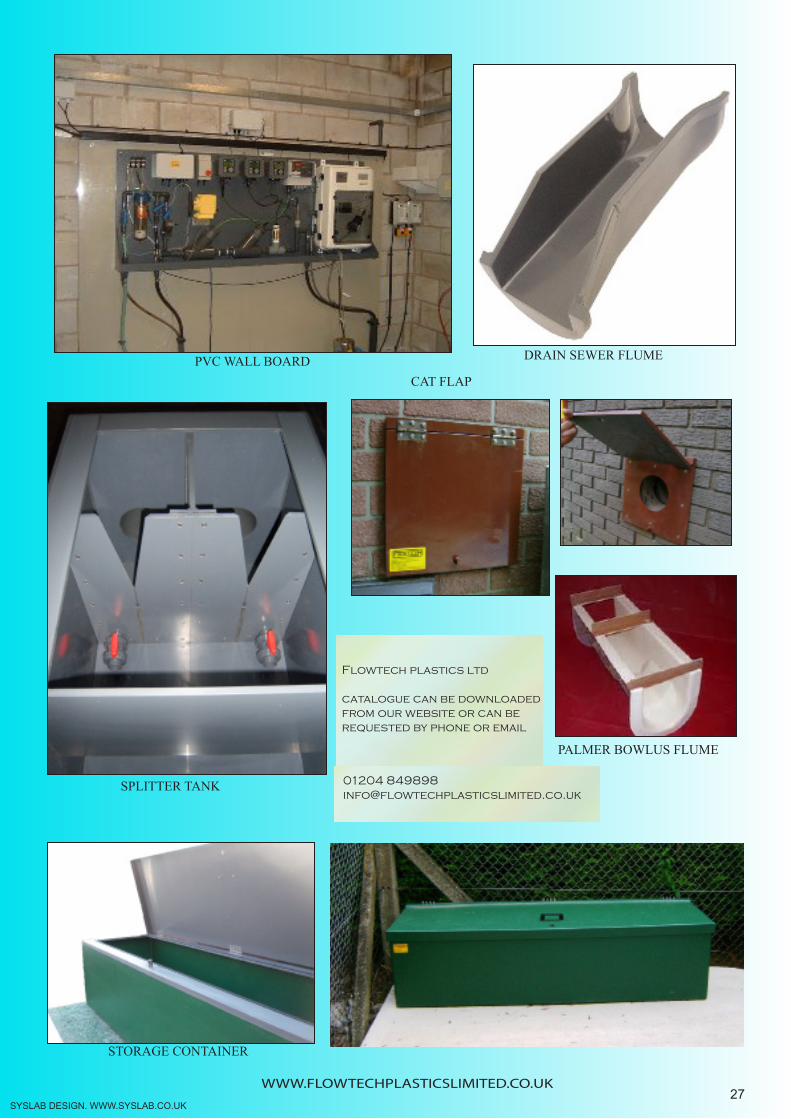
PVC WALL BOARD
STORAGE CONTAINER
CAT FLAP
DRAIN SEWER FLUME
SPLITTER TANK
PALMER BOWLUS FLUME
SYSLAB DESIGN. WWW.SYSLAB.CO.UK
Flowtech plastics ltd
catalogue can be downloadedfrom our website or can berequested by phone or email
01204 [email protected]
27