influencing the electricity/heat production ratio of a ... · pdf fileinfluencing the...
TRANSCRIPT

19/08/2014 1
Ing. Bruno Vanslambrouck, MSc.
UGent – Campus Kortrijk , Research
Group on Thermal Energy in Industry [email protected]
Influencing the electricity/heat production ratio
of a biogas plant by using new technologies
PFI Biotechnology Workshop on 19 August 2014 in Pirmasens
«Experience with Heat Pumps in CHPs»

19/08/2014 2
1. 1. Energy balance of a cogeneration unit
2. 2. The (Organic) Rankine Cycle
3. 3. Alternative: Turbo compound
4. 4. Heat pumps
Presentation Overview

Energy
balance
19/08/2014 3
Gas input
4705 kW
Electricity
2014 kWe ηE = 42,8%
Turbo cooler 186 kW (4,0%)
40°C
Jacket cooling 1011 kW (21,5%)
85-95°C
Exhaust gases 1013 kW (21,5%)
430°→120°C
Ex.: Deutz TCG 2020 V20
ηQ = 43,0 %
Energy Balance CHP Unit

19/08/2014 4
If more E is desired:
- transform (waste) heat of the engine in E by using an adapted
technology
If more (or only) heat is desired: - use a boiler
- keep E produced by the engine but increase the heat flow by using
a thermal driven heat pump
- use shaft power or (part of) the E to drive a compression heat pump
Some explanation about adapted technologies:
Energy Balance CHP Unit
19/08/2014 5
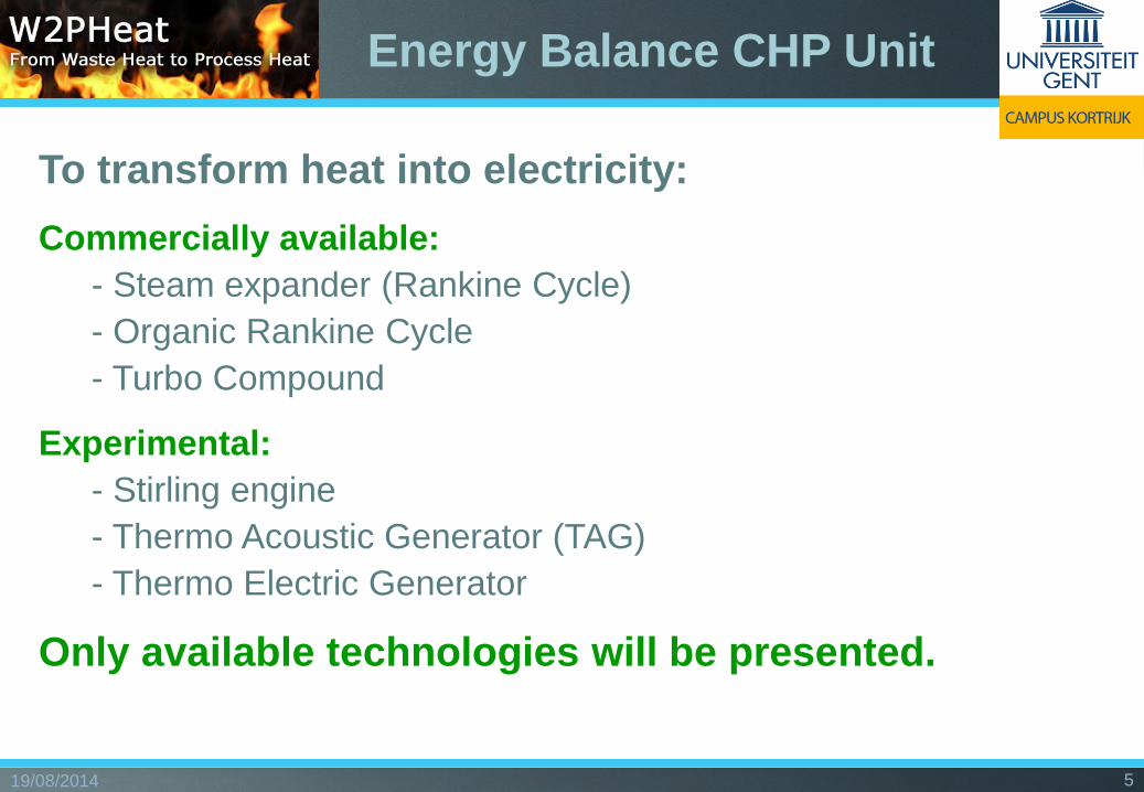
To transform heat into electricity:
Commercially available:
- - Steam expander (Rankine Cycle)
- - Organic Rankine Cycle
- - Turbo Compound
Experimental:
- - Stirling engine
- - Thermo Acoustic Generator (TAG)
- - Thermo Electric Generator
Only available technologies will be presented.
Energy Balance CHP Unit

19/08/2014 6
Steam turbine
installation in a power
plant
1. Boiler 5. Transformer
2. Electrofilter 6. Condensor
3. Steam turbine 7. Cooling tower
4. generator
Source: Electrabel
The (Organic) Rankine
Cycle

19/08/2014 7
Combined Cycle: E-production from recovered heat from the
gasturbine exhaust using a Rankine Cycle
Source: Electrabel
The (Organic) Rankine
Cycle

19/08/2014 8
By using other working fluids, mostly of organic origin, some disadvantages of
water could be avoided:
Organic Rankine Cycle (ORC)
Some candidate fluids:
toluene, butane, pentane,
ammonia, ethanol,
refrigeration fluids (R245fa),
silicone oils…
88
77
66
55
44
33
22
11
7
6
5
4
3
H
21
H
Heat source
Feed pump
Regenerator
Condenser
Expander
Generator
Evaporator
The (Organic) Rankine
Cycle

19/08/2014 9
ORCs are to classify according to:
1. Power range:
- micro-systems: 0,5-10 kWe
- small systems: 10-100 kWe
- medium range: 100-300 kWe
- large systems: 300 kWe – 10 MWe or more
2. Optimal heat source temperature:
- low temperature systems: 55° to 150°C
- medium temperature systems: 150° to 250°C
- high temperature systems: above 250°C
3. Condensor temperature:
- slightly above ambient: no CHP capability
- from 50° to 90°C: usable a CHP by using the condensor heat
ORC Classification

19/08/2014 10
Heat source temperature: 85° 130° 180° 300°and >
ORC efficiency estimation: 5-7% 10-12% 15-17% 18-25%
Important parameters:
- Delta T heat source
- Condensor t°
- ORC design
ORC efficiency

19/08/2014 11
CHP + ORC

Energy
balance
19/08/2014 12
Gas input
4705 kW
Electricity
2014 kWe
Original:
ηE = 42,8%
Turbo cooler 186 kW (4,0%)
40°C ! hORC = 0% (unusable)
Jacket cooling 1011 kW (21,5%)
85-95°C hORC = 6-8%
Eextra = 70 kWe
Exhaust gases 1013 kW (21,5%)
430°→120°C hORC = 20%
Eextra = 200 kWe
Deutz TCG 2020 V20
hORC = 12 % Eextra = 240 kWe
CHP + ORC
CHP + HT+ LT ORC:
ηE = 48,5% 13,4 % more E (ideal)
CHP + LT ORC:
ηE = 47,9% 11,9 % more E (ideal)

19/08/2014 13
Gas input
4705 kW
Electricity
2014 kWe
Turbo cooler
186 kW 40°C
Jacket cooling
1011 kW
2213 kWth ηQ = 47,0% ηTOT = 92,2%
Exhaust gases
1176 kW 430° → 70°C
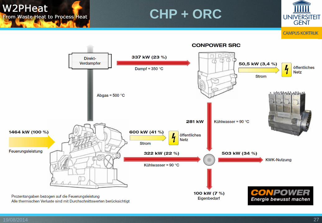
Practical example:
ηE = 46,3% (+ 8,2 % E)
165 kWe
760 kW
416 kW 200° → 70°C
600 kW 50°→ 35°C
ORC Triogen
Deutz TCG 2020 V20
CHP + ORC

19/08/2014 14
CHP + ORC

19/08/2014 15
CHP + ORC

19/08/2014 16
CHP + ORC

19/08/2014 17
CHP + ORC

19/08/2014 18
CHP + ORC

19/08/2014 19
Elektrische Leistung: 35-50 kW
Thermische
Eingangsleistung:
450 - 800 kW
Betriebsdauer: 8.000 h p.a.
Personaleinsatz: 0,05 Mitarbeiter
Eckdaten ORC-IC60-Anlage
ORC-IC60-Anlage zur
Verstromung von Abwärme aus
Biogasmotoren
CHP + ORC

19/08/2014 20
CHP + ORC
19/08/2014 21
CHP + ORC

19/08/2014 22
CHP + ORC

19/08/2014 23
References:
CHP + ORC
19/08/2014 24
CHP + ORC
19/08/2014 25
CHP + ORC

19/08/2014 26
CHP + ORC
19/08/2014 27
CHP + ORC

19/08/2014 28
CHP + ORC

19/08/2014 29
CHP + ORC

19/08/2014 30
CHP + ORC

19/08/2014 31
Feldtestanlage in Kirchwalsede : 2012 wurde das DeVeTec-ORC-System an dem
Blockheizkraftwerk (BHKW) einer Biogasanlage in Kirchwalsede in Betrieb genommen.
CHP + ORC

19/08/2014 32
BEP Europe (Belgium):
Established in 1980
ORC activities started in 2009
Uses a Z- or mono screw
expander
Range:
ORC 1000 power range: from 55 up to 132 kWe
(11 kWe downscaled model in our lab)
ORC 4000 power range: from 250 up to 500 kWe
Heat source: 80°-150°C
Announced efficiency: 6-13% (depending on heat
and cooling source temperatures)
CHP + ORC
19/08/2014 33
CHP + ORC

19/08/2014 34
CHP + ORC

19/08/2014 35
Alternative: Turbo
compound

19/08/2014 36
Alternative: Turbo
compound
For vehicles:
19/08/2014 37
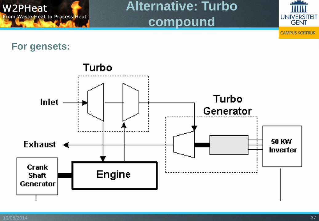
For gensets:
Alternative: Turbo
compound

19/08/2014 38
Alternative: Turbo
compound

19/08/2014 39
Alternative: Turbo
compound
19/08/2014 40
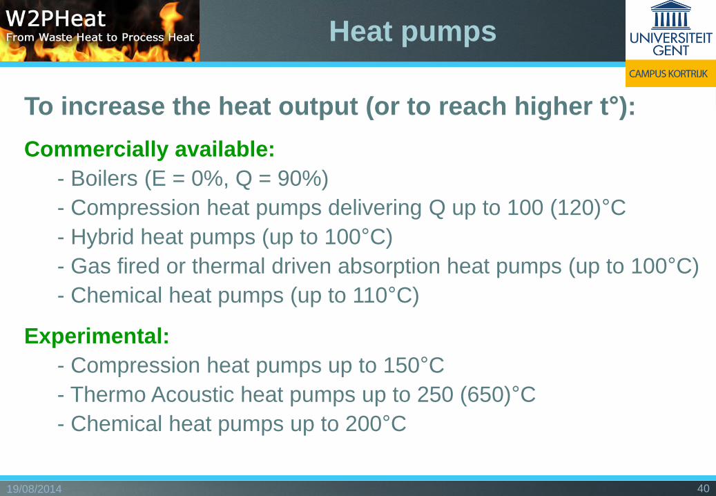
To increase the heat output (or to reach higher t°):
Commercially available:
- - Boilers (E = 0%, Q = 90%)
- - Compression heat pumps delivering Q up to 100 (120)°C
- - Hybrid heat pumps (up to 100°C)
- - Gas fired or thermal driven absorption heat pumps (up to 100°C)
- - Chemical heat pumps (up to 110°C)
Experimental:
- - Compression heat pumps up to 150°C
- - Thermo Acoustic heat pumps up to 250 (650)°C
- - Chemical heat pumps up to 200°C
Heat pumps

19/08/2014 41
Example:
Waste heat temperature: 30°C
Desired process heat temp: 80°C
COP = 353 / (353 – 303) = 7 (Theoretical optimum according to Carnot)
In fact: about 50-60% of Carnot eff., in this case 3,5 à 4,2
Profit of an electrical driven heat pump:
- Primary energy savings when COP > 1/eff E-production, being about 2,5 or PER > 1
- Gain on energy costs if COP > E-price/Heat cost (2,5 à 4 in industry)
Limit (current market supply): ca 100°C !!
Compressor Heat pumps

19/08/2014 42
Heat
Exchanger
Combustion
Engine
Waste Heat
Boiler Condenser
Evaporator
Exhaust Gases, 480°C Expansion
Device
Compressor
4 MW
3 MW
500 kW 650 kW
1 MW η=42% Fuel in: 2,38 MW
95 l/s, 60°C
90°C
70°C 71,3°C
75°C
20°C 20°C
COP = 4
Heat Source (Water) 48 l/s, 40°C
25°C
85°C
Heat Sink
72,9°C
Cooled Exhaust Gases, 90°C
η =P + Q
Fuel=
1 + 1,15
2,38= 90,3%
η =Q
Fuel =
4 + 1,15
2,38= 216%
CHP:
CHP + HP:
Compressor Heat pumps

19/08/2014 43
Source: MAN Dezentrale
Energiesysteme, 1995
Compressor Heat pumps

19/08/2014 44
Compressor Heat pumps

19/08/2014 45
Heat source (Ground) water, waste water
Engine VW (VR6) gas engine
Refrigerant R134a
Heating capacity 200, 300 and 400 kW
Compressor type Recipro piston(Bitzer)
Number of compressors 2 (except 200 kW machine)
Power adjustment 25 – 100 % (fully modulating)
Temperature heat source 5°C - 30°C
Temperature heat supply 45°C - 80°C
COP heating 5,22 – 7,48 (PER 2,23)
Cooling capacity 110kW – 230kW
EER cooling 2,66 – 4,47 (PER 1)
Compressor Heat pumps

19/08/2014 46 22/05/201
4
46 11/12/2012 46
Absorption Heat pumps
Type I
19/08/2014 47
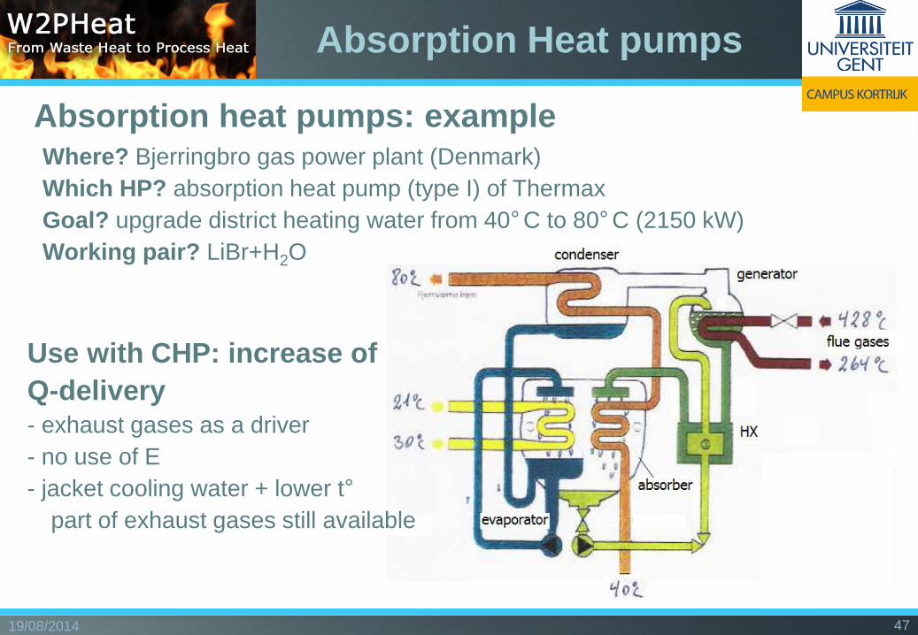
Absorption heat pumps: example • Where? Bjerringbro gas power plant (Denmark)
• Which HP? absorption heat pump (type I) of Thermax
• Goal? upgrade district heating water from 40° C to 80° C (2150 kW)
• Working pair? LiBr+H2O
Use with CHP: increase of
Q-delivery - exhaust gases as a driver
- no use of E
- jacket cooling water + lower t°
- part of exhaust gases still available
Absorption Heat pumps

19/08/2014 48
Some suppliers:
• Robur / Ener-G / CoolingWays
• Fulton
• Thermax
• Moretek Systems Inc. / Shuangliang Eco-Energy
• Buderus
• Hitachi
• Yazaki
• Broad USA
• Colibri
www.robur.com
www.broadusa.com www.shuangliang.com
Absorption Heat pumps

19/08/2014 49
Source: ECN, Petten (Nl)
Chemical Heat Transformer
Use with CHP: increase t°-level of jacket cooling water
Type II

19/08/2014 50
Ing Bruno Vanslambrouck, MSc.
UGent dept. Industrial Product and System design (ISP)
Research Group on Thermal Energy in Industry (TEI)
Graaf Karel de Goedelaan 5, B-8500 Kortrijk
Mail: [email protected]
Tel: +32 56 241211 of +32 56 241227 (dir)
www.tei.ugent.be www.orcnext.be
www.cornet-w2pheat.eu www.wasteheat.eu
Thanks for your attention.
Questions ???