influence of reynolds numbers on the flow and heat...
TRANSCRIPT
INFLUENCE OF REYNOLDS NUMBERS ON THE FLOW AND HEAT TRANSFER AROUND ROW OF MAGNETIC OBSTACLES
Xidong Zhang College of Energy and Power Engineering,
Nanjing Institute of Technology, Nanjing 211167, China College of Astronautics,
Nanjing University of Aeronautics and Astronautics,
Nanjing 210016, China
Guiping Zhu College of Astronautics,
Nanjing University of Aeronautics and Astronautics,
Nanjing 210016, China
Yin Zhang College of Astronautics,
Nanjing University of Aeronautics
and Astronautics, Nanjing 210016, China
Hongyan Wang College of Energy and Power
Engineering, Nanjing Institute of Technology,
Nanjing 211167, China
Hulin Huang College of Astronautics,
Nanjing University of Aeronautics
and Astronautics, Nanjing 210016, China
ABSTRACT An incompressible electrically conducting viscous fluid
flow influenced by a local external magnetic field may develop vortical structures and eventually instabilities similar to those observed in flows around bluff bodies(such as circular cylinder), denominated magnetic obstacle. The present investigation analyses numerically the three-dimensional flow and heat transfer around row of magnetic obstacles. The vortex structures of magnetic obstacles, heat transfer behaviors in the wake of magnetic obstacles and flow resistance are analyzed at different Reynolds numbers. It shows that the flow behind magnetic obstacles contains four different regimes: (1) one pair of magnetic vortices, (2) three pairs namely, magnetic, connecting, and attached vortices, (3) smaller vortex shedding from the in-between magnetic obstacles, i.e. quasi-static and (4) regular vortex shedding from the row of magnetic obstacles. Furthermore, downstream cross-stream mixing induced by the unstable wakes can enhance wall-heat transfer, and the maximum value of percentage heat transfer increment (HI) is equal to about 35%. In this case, the thermal performance factor is more than one.
INTRODUCTION The electrically conducting fluid is decelerated by the
external magnetic field due to the Lorentz force produced by the interaction of an external magnetic field with induce electric currents. This retarding effect of external magnetic field (uniform or non-uniform magnetic field) widely exists in Tokamak toroidal confinement fusion systems, electromagnetic brake and the interaction of aerodynamics and electromagnetic dynamics [1, 2]. However, the main goal of those works was to investigate the so-called M-shaped velocity profile in the past [3, 4]. Recently Cuevas et al. [5, 6] have found a vortex dipole in a creeping flow under non-uniform local magnetic field (magnetic obstacle), and discovered the periodic vortex shedding in the wake of magnetic obstacle at Reynolds numbers 100 and 200. Votyakov et al. [7] showed that an electrically conducting fluid past a magnetic obstacle can form a vortex-pair and complex six-vortex patterns at appropriate interaction parameter (N), Reynolds number (Re) and constrainment factor (κ) for the first time in the three-dimensional numerical simulation and experiment. Andreev et al. [8] devised an experiment of the liquid metal past a magnetic obstacle in a rectangular channel and proved that the interaction parameter N governed the flow when turbulent pulsations were suppressed by the external magnetic field. Votyakov et al. [9] reported the
Proceedings of the ASME 2016 5th International Conference on Micro/Nanoscale Heat and Mass Transfer MNHMT2016
January 4-6, 2016, Biopolis, Singapore
MNHMT2016-6455
1 Copyright © 2016 by ASME

effect of constrainment factor on flow pattern, and investigated the three-dimensional characteristic of the flow past a magnetic obstacle. Votyakov and Kassinos [10] firstly detected the vortex shedding can be either symmetric or asymmetric depending on the inlet and initial conditions in the three-dimensional simulation. Kenjereš et al. [11] investigated numerically the vortical structures and turbulent bursts behind a magnetic obstacle in transitional flow regimes. Their results revealed that the turbulence was sustained locally in the proximity of the magnetic wake edge. And the rapid turbulence decay indicated that the flow will fully relaminarise farther downstream.. Zhang and Huang [12-15] investigated the effect of stable vortex structures and periodic vortex shedding on heat transfer characteristic and drag of circular cylinder at various dimensionless parameters (N, Re, κ, β and L/D). All the above investigations were performed for single magnetic obstacle. Kenjereš [16] analyzed local heat transfer features of fluid region past different magnetic dipole configurations (one magnetic dipole, two magnetic dipoles placed side-by-side, and three magnetic dipoles placed triangularly) with a fixed inflow condition of Re=103 in a channel. Zhang and Huang [17, 18] showed the influence of separation ratios and interaction number on flow and heat transfer for a row of magnetic obstacles at Re≥600.
The literature survey shows that although there are some investigations for single and multiple magnetic obstacles, there is limited quantitative information on the wall-heat transfer and flow for a row of magnetic obstacles in the available papers. In contrast to hundreds papers published for ordinary solid obstacles (circular and square cylinders, and a row of square cylinders) by many authors [19-21], the heat transfer and flow characteristics of an electrically conducting fluid around a row of magnetic obstacles still be a rather new magnetohydrodynamic (MHD) problem that is not yet completely understood up to now. It has been established that the interaction of wake vortices with a boundary layer adjacent to a heated wall and the transport mechanism of wake vortices enhances heat transfer through the wall for a row of magnetic obstacles [17, 18]. Considering the limits of the Reynolds number we have two scenarios: at the limit of small Reynolds number, different vortex structures will lead to various heat transfer effect, and as the Reynolds number becomes large, attached vortices are instable and heat transfer will increase from the heated wall. This study aims to establish the relationship between Reynolds number and heat transfer, pressure drop penalty for three-dimensional MHD duct flow.
NOMENCLATURE A side-wall surface b induced magnetic field intensity B magnetic field intensity B0 application magnetic intensity f friction factor g* separation ratio Ha Hartmann number
HI heat transfer increment J current density L characteristic dimension Mx, My, H characteristic magnet dimensions N interaction parameter Nu local Nusselt number
Nu surface-averaged Nusselt number
Nu time and surface-averaged Nusselt number
p pressure Pr prandtl number Pe Peclet number Re Reynolds number Rem magnetic Reynolds number t time T temperature field T0 free stream temperature Tf bulk fluid temperature Tw hot wall temperature u0 the area-averaged inflow velocity u velocity vector (u, v, w) x, y, z Cartesian coordinate Greek symbols m magnetic permeability (H/m)
kinematic viscosity (m2/s) fluid density (kg/m3) electrical conductivity (1/Ω•m)
p period of time integration
thermal performance factor
Subscripts w wall m magnetic 0 absent magnetic obstacles
2. COMPUTATIONAL DETAILS
2.1. Computational domain and mathematical
equations
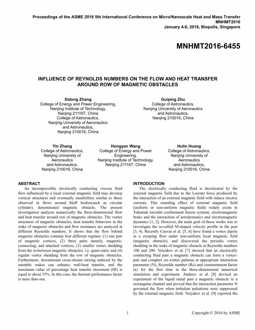
The flow configuration is shown in Fig. 1. The rectangular duct with a length (x) of 0.08m, width (y) of 0.05cm, and height (z) of 0.02m is filled with the eutectic alloy GaInSn with a typical composition of 68.5% Ga, 21.5% In, and 10% Sn respectively. Each external magnetic field is produced by the superposition of two parallel permanent magnets, uniformly polarized in the normal direction. The area of these magnets is only a small fraction of the total flow domain. The distance between two consecutive magnetic obstacles is the same G/My=2. The characteristic length scale L is the half-height of the duct. The external magnetic field is imposed by solving a semianalytical simplification of the Biot-Savart and Maxwell equations [9-18] with following parameters: (Mx, My, H)=(0.03, 0.04, 0.03)m.
2 Copyright © 2016 by ASME
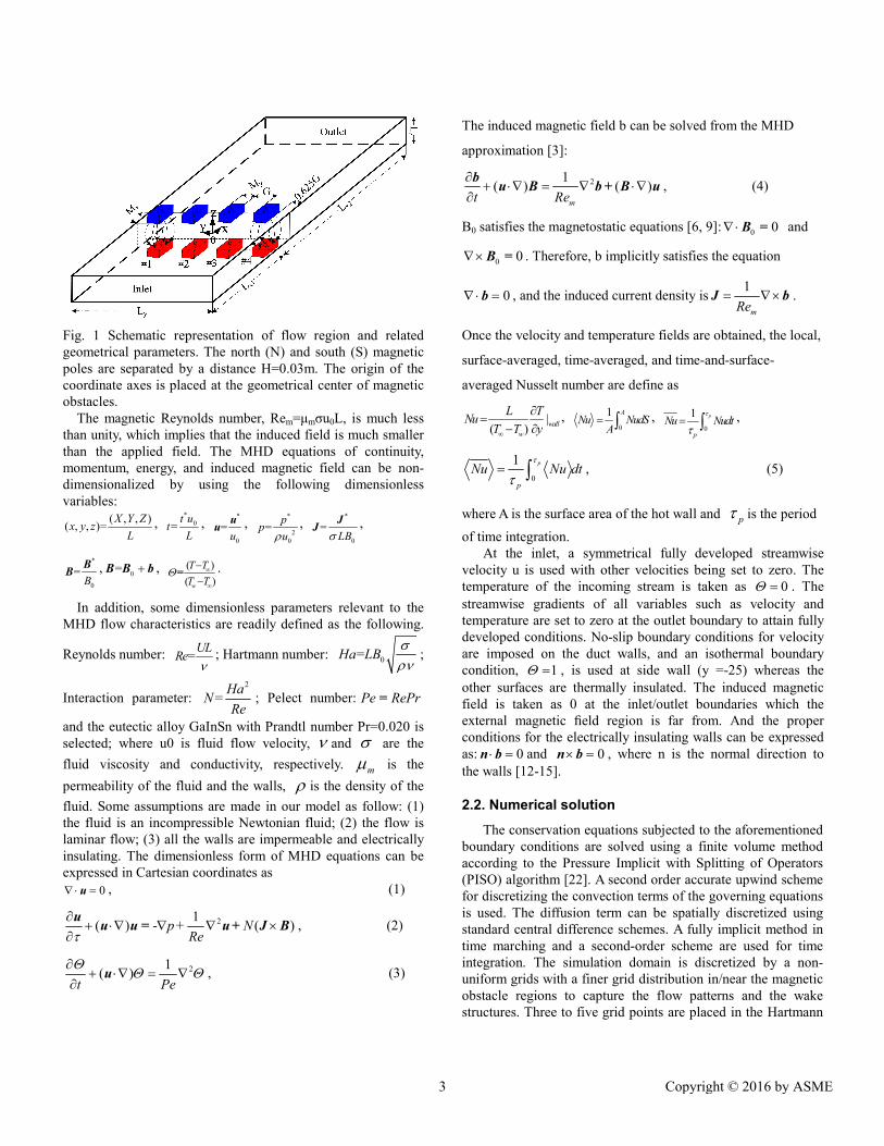
Fig. 1 Schematic representation of flow region and related geometrical parameters. The north (N) and south (S) magnetic poles are separated by a distance H=0.03m. The origin of the coordinate axes is placed at the geometrical center of magnetic obstacles.
The magnetic Reynolds number, Rem=μmσu0L, is much less than unity, which implies that the induced field is much smaller than the applied field. The MHD equations of continuity, momentum, energy, and induced magnetic field can be non-dimensionalized by using the following dimensionless variables:
( , , )( , , )=
X Y Zx y z
L,
*0=
t ut
L,
*
0
=u
uu ,
*
20
=p
pu
, *
0
=LB
JJ ,
*
0
=B
BB ,
0= B B b , ( )
( )w
T T
T T
= .
In addition, some dimensionless parameters relevant to the MHD flow characteristics are readily defined as the following.
Reynolds number:
=UL
Re
; Hartmann number: 0=Ha LB
;
Interaction parameter: 2
=Ha
NRe
; Pelect number: Pe RePr=
and the eutectic alloy GaInSn with Prandtl number Pr=0.020 is selected; where u0 is fluid flow velocity, and are the
fluid viscosity and conductivity, respectively. m is the
permeability of the fluid and the walls, is the density of the
fluid. Some assumptions are made in our model as follow: (1) the fluid is an incompressible Newtonian fluid; (2) the flow is laminar flow; (3) all the walls are impermeable and electrically insulating. The dimensionless form of MHD equations can be expressed in Cartesian coordinates as
0 u , (1)
21( ) - ( )p+ N
Re
uu u = u+ J B , (2)
21( )
t Pe
u , (3)
The induced magnetic field b can be solved from the MHD
approximation [3]:
21( ) ( )
mt Re
bu B b+ B u , (4)
B0 satisfies the magnetostatic equations [6, 9]: 0 0B = and
0 0B = . Therefore, b implicitly satisfies the equation
0 b , and the induced current density is1
mRe J b .
Once the velocity and temperature fields are obtained, the local,
surface-averaged, time-averaged, and time-and-surface-
averaged Nusselt number are define as
|( )
wall
w
L TNu
T T y
,
0
1 A
Nu NudSA
, 0
1 p
p
Nu Nudt
,
0
1 p
p
Nu Nu dt
, (5)
where A is the surface area of the hot wall and p is the period
of time integration. At the inlet, a symmetrical fully developed streamwise
velocity u is used with other velocities being set to zero. The temperature of the incoming stream is taken as . The streamwise gradients of all variables such as velocity and temperature are set to zero at the outlet boundary to attain fully developed conditions. No-slip boundary conditions for velocity are imposed on the duct walls, and an isothermal boundary condition, , is used at side wall (y =-25) whereas the other surfaces are thermally insulated. The induced magnetic field is taken as 0 at the inlet/outlet boundaries which the external magnetic field region is far from. And the proper conditions for the electrically insulating walls can be expressed as: 0 n b and 0 n b , where n is the normal direction to the walls [12-15].
2.2. Numerical solution
The conservation equations subjected to the aforementioned boundary conditions are solved using a finite volume method according to the Pressure Implicit with Splitting of Operators (PISO) algorithm [22]. A second order accurate upwind scheme for discretizing the convection terms of the governing equations is used. The diffusion term can be spatially discretized using standard central difference schemes. A fully implicit method in time marching and a second-order scheme are used for time integration. The simulation domain is discretized by a non-uniform grids with a finer grid distribution in/near the magnetic obstacle regions to capture the flow patterns and the wake structures. Three to five grid points are placed in the Hartmann
3 Copyright © 2016 by ASME

layers according to Ni et al.[23]. These three sets of grid produced similar flow patterns and vortex structure, and the
Nusselt number uN and pressure drop (ΔP) just show small
grid dependence. Therefore, the computational domain is discretized with a mesh of 141x133y67z. In comparison with the studies of Votyakov et al.[10] and Kenjereš[16] we believe that the number of grid meshes is sufficient for the solution precision. All the cases are performed using 6-8 CPUs on the local Beowulf-Linux cluster.
Table 1 Grid convergence index values at Re=600 Mesh 130×120×67 141×133×67 155×150×67
Nu
6.85 7.02 7.11
ΔP 4.31 4.35 4.40
3. RESULTS AND DISCUSSION
3.1 Validation of the numerical system
(a)
(b)
(c)
(d)
(e)
(f)
Fig. 2 Comparison of wake structure from a magnetic obstacle. (a,d) Present simulation, (b,e) numerical simulation of Votyakov et al.[7] and (c) experiments of Samsami et al. [24].
Validation was performed against published results to ensure the accuracy of the present formulation and model. The flow structures for a magnetic obstacle as obtained numerically by Votyakov et al.[7] and experimentally by Samsami et al. [24]. are compared with the present simulation in Fig. 2, and an exceptionally close agreement is observed in terms of the vortex structures downstream the magnetic obstacle.
(a)
(b)
4 Copyright © 2016 by ASME
(c)
Fig. 3 Time traces of the spanwise component of velocity (v) at monitoring points M1 and M2 at N=9: (a)Re=400; (b)Re=500 and (c)Re=600.
3.2 Wake of magnetic obstacles
Figure 3 shows the time series of the spanwise velocity (v) at monitoring point M1 (35, 18, 20) and M2 (35. 6. 0) for two adjacent magnetic obstacles (such as #1 and #2). In the initial stage of the flow it is found that spanwise velocity first fluctuate then subsequently tends to be stable with an increase in the flow time due to the formation and development of magnetic vortices, as shown in Fig. 3(a). This phenomenon indicates that the wake of magnetic obstacles still be stable at Re=400. But the attached vortices may be elongated along the streamwise direction in comparison with that of single magnetic obstacle. With the increase of Reynolds number, the spanwise velocity at monitoring point begin to fluctuate slightly, see Fig. 3(b), which shows that the wakes of magnetic obstacles will changed from the stable to unstable. This mechanism is similar to that of single magnetic obstacle. The fluctuations of the spanwise velocity is very obvious when Re=600, so that period vortex shedding occurs in the wake of magnetic obstacles.
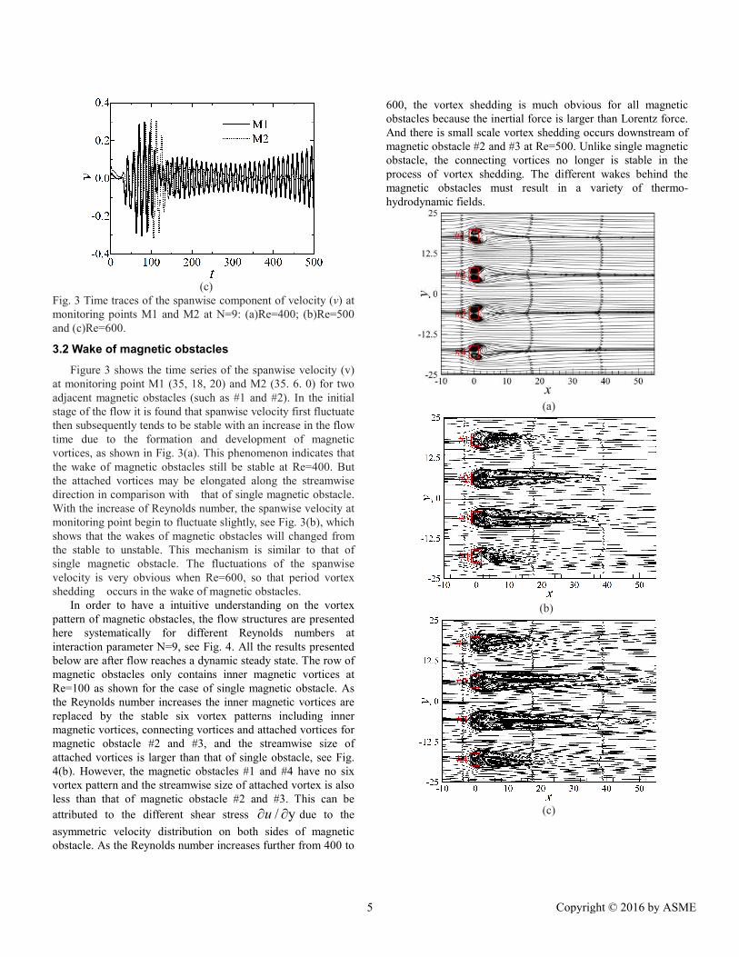
In order to have a intuitive understanding on the vortex pattern of magnetic obstacles, the flow structures are presented here systematically for different Reynolds numbers at interaction parameter N=9, see Fig. 4. All the results presented below are after flow reaches a dynamic steady state. The row of magnetic obstacles only contains inner magnetic vortices at Re=100 as shown for the case of single magnetic obstacle. As the Reynolds number increases the inner magnetic vortices are replaced by the stable six vortex patterns including inner magnetic vortices, connecting vortices and attached vortices for magnetic obstacle #2 and #3, and the streamwise size of attached vortices is larger than that of single obstacle, see Fig. 4(b). However, the magnetic obstacles #1 and #4 have no six vortex pattern and the streamwise size of attached vortex is also less than that of magnetic obstacle #2 and #3. This can be
attributed to the different shear stress / yu due to the
asymmetric velocity distribution on both sides of magnetic obstacle. As the Reynolds number increases further from 400 to
600, the vortex shedding is much obvious for all magnetic obstacles because the inertial force is larger than Lorentz force. And there is small scale vortex shedding occurs downstream of magnetic obstacle #2 and #3 at Re=500. Unlike single magnetic obstacle, the connecting vortices no longer is stable in the process of vortex shedding. The different wakes behind the magnetic obstacles must result in a variety of thermo-hydrodynamic fields.
(a)
(b)
(c)
5 Copyright © 2016 by ASME

(d)
Fig. 4 Instantaneous mass flow streamlines on the z=0 plane at N=9. The solid rectangle shows the borders of the external magnet: (a)Re =100; (b)Re=400; (c)Re=500; and (d)Re=600.
3.3 Heat tranafer
To represent the effect of Reynolds number on the temperature field, the local heated wall Nusselt number Nu/Nu0 is plotted in Fig. 5(a) for Re=100, 400, 500 and 600 at interaction parameter N=9. For all Reynolds numbers, it is found that the value of Nu/Nu0 first increases and then subsequently decreases and fluctuates as the streamwise coordinate x increases. It is worthwhile mentioning that the Nusselt number distribution is regular when Re≤500 because the fluid flow still be stable, Fig. 4(a-c). Furthermore, the Nusselt number increases monotonically with the increasing in Reynolds number, once Reynolds number exceeds 400 the increase is not remarkable for the stable flow pattern. In the vicinity of x=0 the thermal boundary layer is thin because the magnetic obstacles accelerate the flow near the heated wall, and magnetic vortices drive the surrounding fluid flow. So that the Nusselt number. is maximum. The distribution of skin friction coefficient fc/fc0 is similar to that of Nusselt number, as shown in Fig. 5(b).
In order to further obtain the quantitative effect of Reynolds number on the heat transfer, Fig. 6 gives the overall increment of heat transfer HI. Here the overall increment of heat transfer HI
is defined as 0
100%0
Nu NuHI
Nu
. According to this calculation
method, the heat transfer is enhanced for all Reynolds number, and the increment increases with a increasing in Reynolds number. Because the high temperature fluid can be carried by the vortical flow near the heated wall and then the fluid is convected away by the wake interaction, which leads to better mix with the low-temperature fluid. The maximum value of the overall heat transfer increment is about 35% at Re=600. As is well known, the enhancement in heat transfer is associated with pressure drop penalty. The pressure drop penalty displays an increased dependence on Reynolds number, with increasing
Reynolds number resulting in an increased pressure drop penalty, see Fig. 6.
(a)
(b)
Fig. 5 Local Nusselt number Nu/Nu0 (a) and local skin friction coefficient fc/fc0 (b) over the heated surface on the side wall y=-25 as a function of coordinate x.
Fig. 6 Variations of the percentage increment of the overall heat transfer (HI) and pressure drop penalty (ΔPpenalty).
In MHD channel flows, the performance analysis is important to determine whether the method employed to enhance the heat transfer from the viewpoint of energy. Figure 7 presents the effect of Reynolds number on the thermal performance factor. The thermal performance factor η first decreases then subsequently increases with an increasing in Re.
6 Copyright © 2016 by ASME
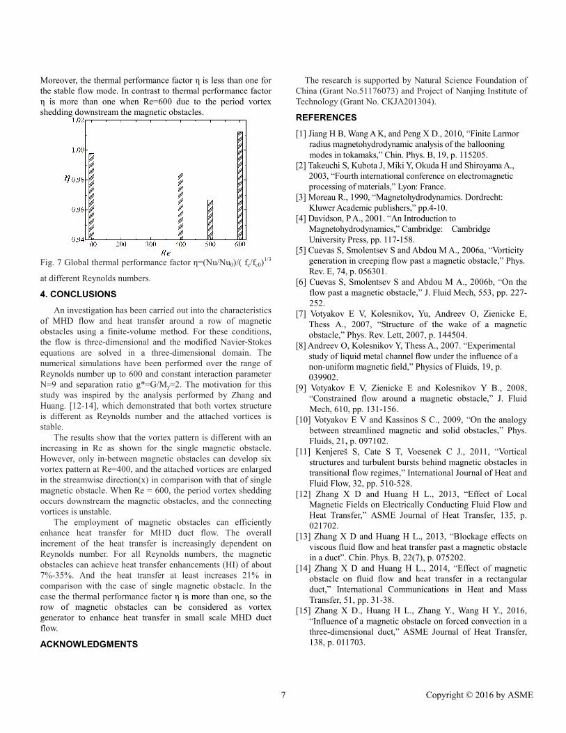
Moreover, the thermal performance factor η is less than one for the stable flow mode. In contrast to thermal performance factor η is more than one when Re=600 due to the period vortex shedding downstream the magnetic obstacles.
Fig. 7 Global thermal performance factor η=(Nu/Nu0)/( fc/fc0)
1/3
at different Reynolds numbers.
4. CONCLUSIONS
An investigation has been carried out into the characteristics of MHD flow and heat transfer around a row of magnetic obstacles using a finite-volume method. For these conditions, the flow is three-dimensional and the modified Navier-Stokes equations are solved in a three-dimensional domain. The numerical simulations have been performed over the range of Reynolds number up to 600 and constant interaction parameter N=9 and separation ratio g*=G/My=2. The motivation for this study was inspired by the analysis performed by Zhang and Huang. [12-14], which demonstrated that both vortex structure is different as Reynolds number and the attached vortices is stable.
The results show that the vortex pattern is different with an increasing in Re as shown for the single magnetic obstacle. However, only in-between magnetic obstacles can develop six vortex pattern at Re=400, and the attached vortices are enlarged in the streamwise direction(x) in comparison with that of single magnetic obstacle. When Re = 600, the period vortex shedding occurs downstream the magnetic obstacles, and the connecting vortices is unstable.
The employment of magnetic obstacles can efficiently enhance heat transfer for MHD duct flow. The overall increment of the heat transfer is increasingly dependent on Reynolds number. For all Reynolds numbers, the magnetic obstacles can achieve heat transfer enhancements (HI) of about 7%-35%. And the heat transfer at least increases 21% in comparison with the case of single magnetic obstacle. In the case the thermal performance factor η is more than one, so the row of magnetic obstacles can be considered as vortex generator to enhance heat transfer in small scale MHD duct flow.
ACKNOWLEDGMENTS
The research is supported by Natural Science Foundation of China (Grant No.51176073) and Project of Nanjing Institute of Technology (Grant No. CKJA201304).
REFERENCES
[1] Jiang H B, Wang A K, and Peng X D., 2010, “Finite Larmor radius magnetohydrodynamic analysis of the ballooning modes in tokamaks,” Chin. Phys. B, 19, p. 115205.
[2] Takeuchi S, Kubota J, Miki Y, Okuda H and Shiroyama A., 2003, “Fourth international conference on electromagnetic processing of materials,” Lyon: France.
[3] Moreau R., 1990, “Magnetohydrodynamics. Dordrecht: Kluwer Academic publishers,” pp.4-10.
[4] Davidson, P A., 2001. “An Introduction to Magnetohydrodynamics,” Cambridge: Cambridge University Press, pp. 117-158.
[5] Cuevas S, Smolentsev S and Abdou M A., 2006a, “Vorticity generation in creeping flow past a magnetic obstacle,” Phys. Rev. E, 74, p. 056301.
[6] Cuevas S, Smolentsev S and Abdou M A., 2006b, “On the flow past a magnetic obstacle,” J. Fluid Mech, 553, pp. 227-252.
[7] Votyakov E V, Kolesnikov, Yu, Andreev O, Zienicke E, Thess A., 2007, “Structure of the wake of a magnetic obstacle,” Phys. Rev. Lett, 2007, p. 144504.
[8] Andreev O, Kolesnikov Y, Thess A., 2007. “Experimental study of liquid metal channel flow under the influence of a non-uniform magnetic field,” Physics of Fluids, 19, p. 039902.
[9] Votyakov E V, Zienicke E and Kolesnikov Y B., 2008, “Constrained flow around a magnetic obstacle,” J. Fluid Mech, 610, pp. 131-156.
[10] Votyakov E V and Kassinos S C., 2009, “On the analogy between streamlined magnetic and solid obstacles,” Phys. Fluids, 21, p. 097102.
[11] Kenjereš S, Cate S T, Voesenek C J., 2011, “Vortical structures and turbulent bursts behind magnetic obstacles in transitional flow regimes,” International Journal of Heat and Fluid Flow, 32, pp. 510-528.
[12] Zhang X D and Huang H L., 2013, “Effect of Local Magnetic Fields on Electrically Conducting Fluid Flow and Heat Transfer,” ASME Journal of Heat Transfer, 135, p. 021702.
[13] Zhang X D and Huang H L., 2013, “Blockage effects on viscous fluid flow and heat transfer past a magnetic obstacle in a duct”. Chin. Phys. B, 22(7), p. 075202.
[14] Zhang X D and Huang H L., 2014, “Effect of magnetic obstacle on fluid flow and heat transfer in a rectangular duct,” International Communications in Heat and Mass Transfer, 51, pp. 31-38.
[15] Zhang X D., Huang H L., Zhang Y., Wang H Y., 2016, “Influence of a magnetic obstacle on forced convection in a three-dimensional duct,” ASME Journal of Heat Transfer, 138, p. 011703.
7 Copyright © 2016 by ASME
[16] Kenjereš S., 2012, “Energy spectra and turbulence generation in the wake of magnetic obstacles,” Phys. Fluids, 24, p. 115111.
[17] Zhang X D, Huang H L, and Wang H Y., 2014, “Flow and heat transfer past row of magnetic obstacles for various separation ratios,” International Communications in Heat and Mass Transfer, 59, pp. 178-187.
[18] Zhang X D and Huang H L., 2015, “Heat transfer enhancement of MHD flow by a row of magnetic obstacles,” Heat Transfer Research, 46(11), pp. 1-21.
[19] Kumar S R, Sharma A. and Agrawal A., 2008, “Simulation of flow around a row of square cylinders,” J. Fluid Mech. 606, pp. 369-397.
[20] Chatterjee D, Biswas G and Amiroudine S., 2009, “Numerical investigation of forced convection heat transfer in unsteady flow past a row of square cylinders,” Int. J. Heat Fluid Flow, 30, pp. 1114-1128.
[21] Chatterjee D, Biswas G and Amiroudine S., 2010, “Numerical simulation of flow past row of square cylinders for various separation ratios,” Computers & Fluids, 39, pp. 49-59.
[22] Issa, R I., 1986, “Solution of the implicitly discretized fluid flow equations by operator splitting,” J. Comp. Phys, 62, pp. 40-65.
[23] Ni M J, Munipalli R and Morley N B., 2007, “A Current Density Conservative Scheme for Incompressible MHD Flows at a Low Magnetic Reynolds Number. Part I: On a Rectangular Collocated Grid System,” J. Comput. Phys, 227, pp. 174-204.
[24] Samsami, F., Kolesnikov, Y., Thess, A., 2014, “Vortex dynamics in the wake of a magnetic obstacle,” J Vis., 17, pp. 245-252.
8 Copyright © 2016 by ASME